
Development of Hydrogen–Oxygen Fuel Cells Based on Anion-Exchange Electrolytes and Catalysts with Reduced Platinum Content

 , and
, and
Abstract
:1. Introduction
2. Materials and Methods
2.1. Catalysts Synthesis
2.1.1. The Synthesis of the Cathode Catalyst
2.1.2. Synthesis of PtMo/CNTN Anode Catalysts
2.1.3. Polyol Synthesis of Pt/CNTN Catalyst
2.2. Methods of Electrochemical Characteristics under Model Conditions
2.3. Methods for Studying the Structure of Catalysts
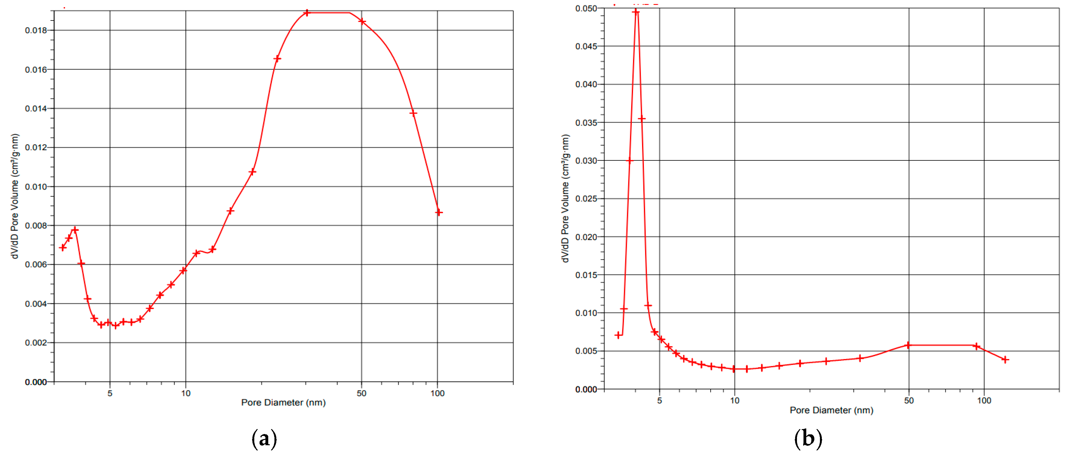
2.3.1. Brunauer–Emmett–Teller (BET) Method
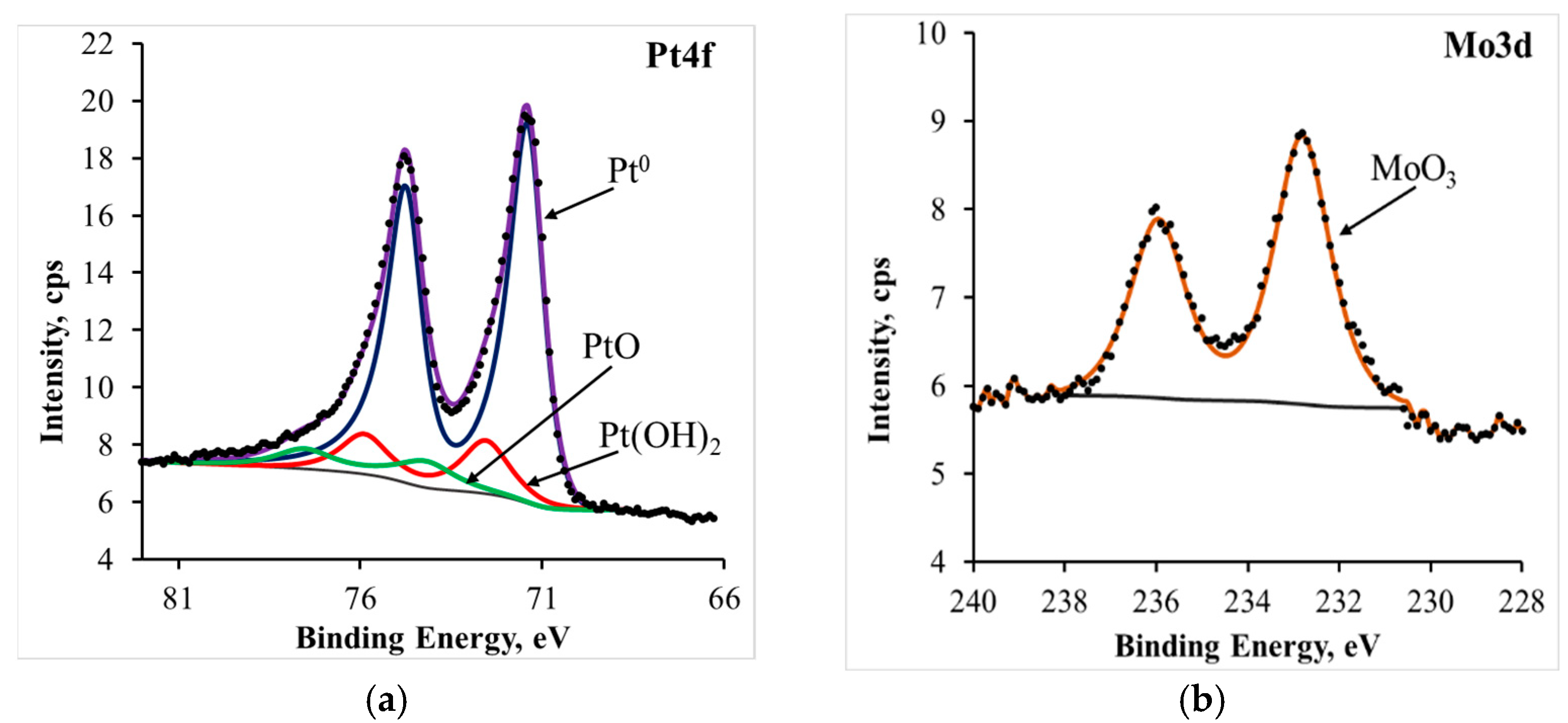
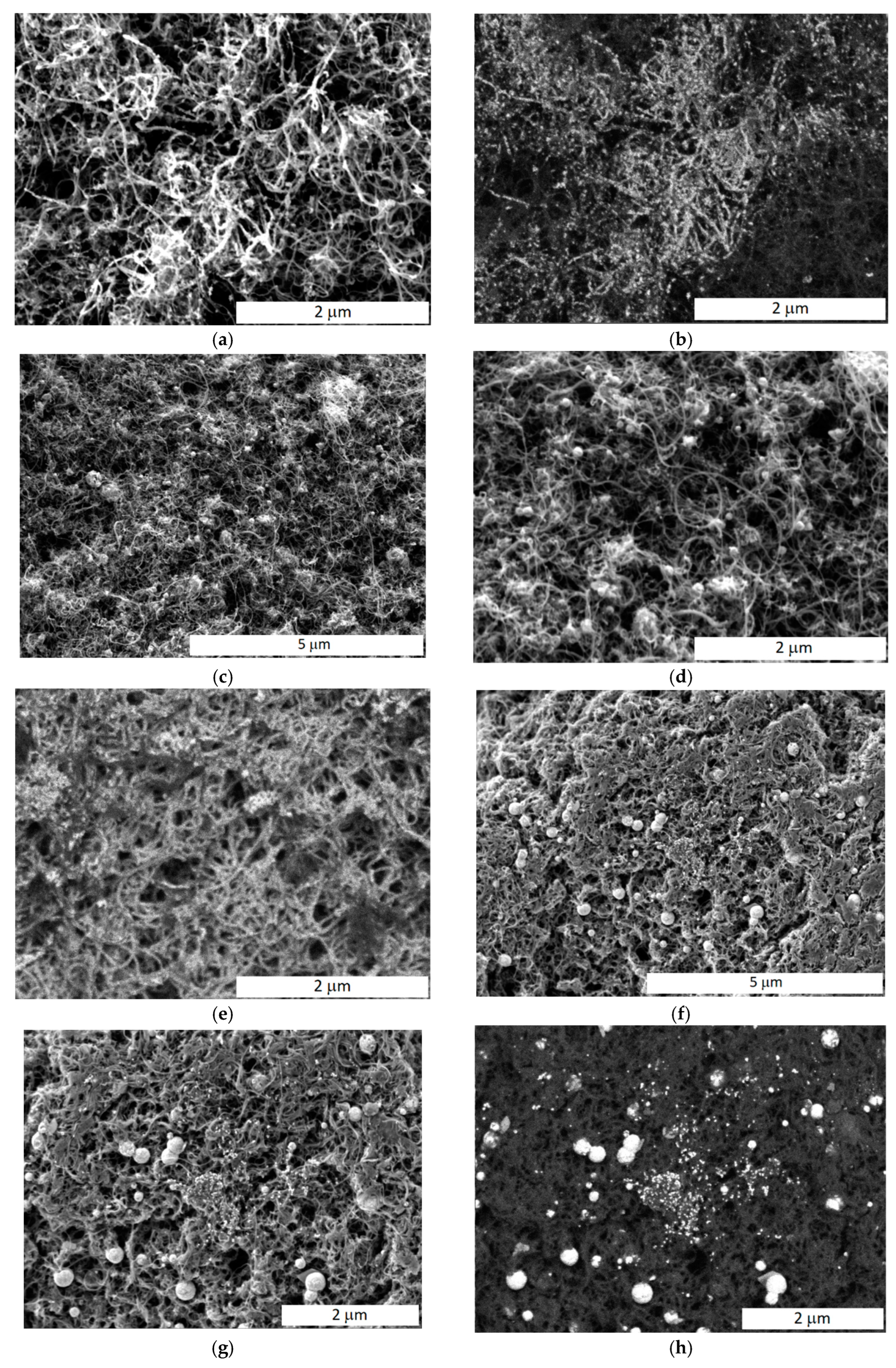
2.3.2. X-ray Photoelectron Spectra (XPS) and Scanning Electron Microscopy
2.4. Spectrophotometric Measurements
2.5. Methodology for Forming and Testing AEMFC-Based MEAs
3. Results and Discussion
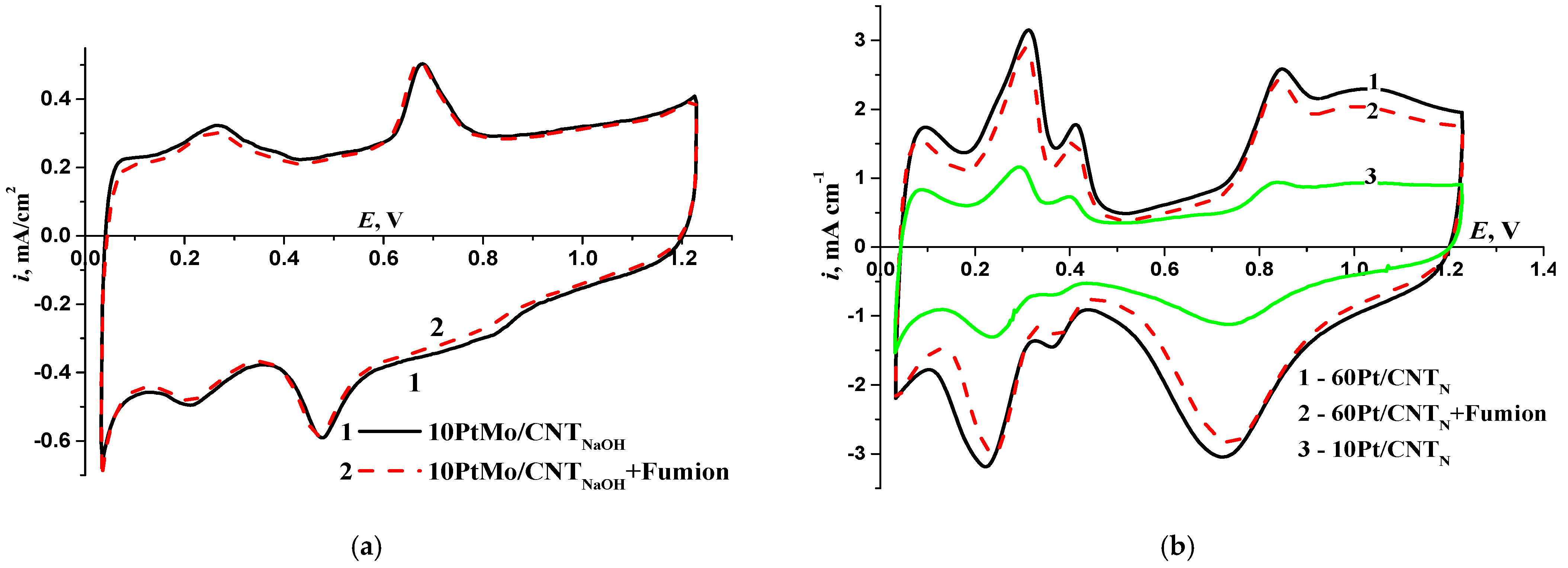
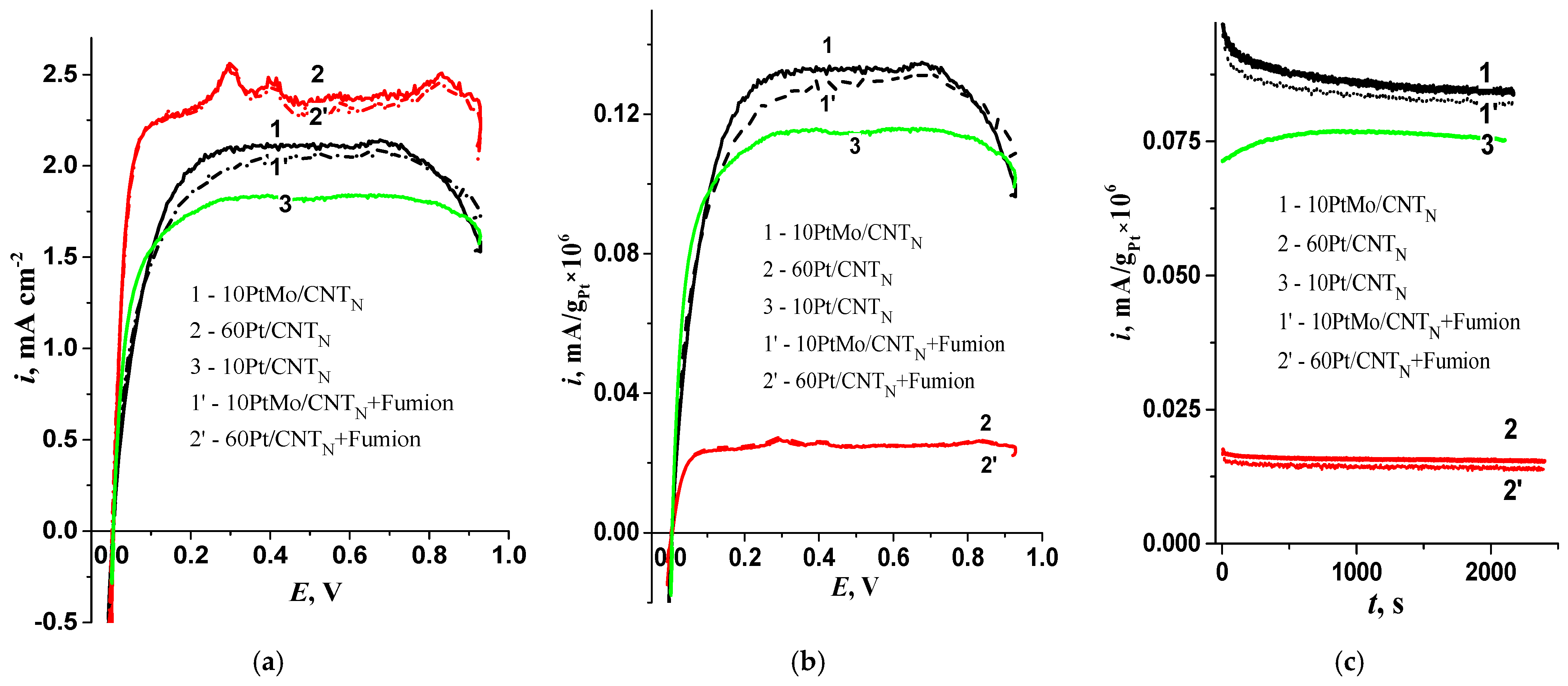
3.1. Electrochemical Characteristics of Catalysts under Model Conditions
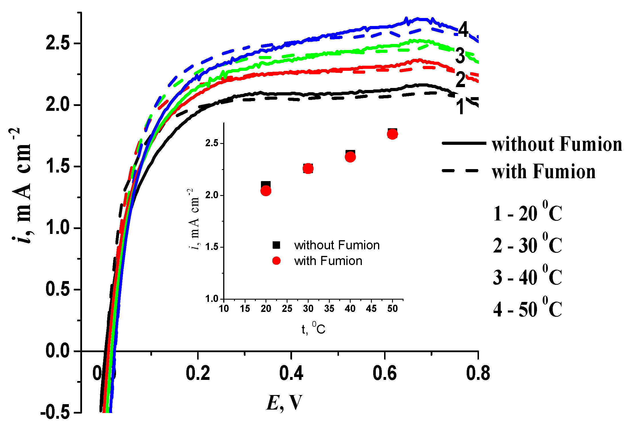
3.2. The Impact of Temperature on Hydrogen Electrooxidation
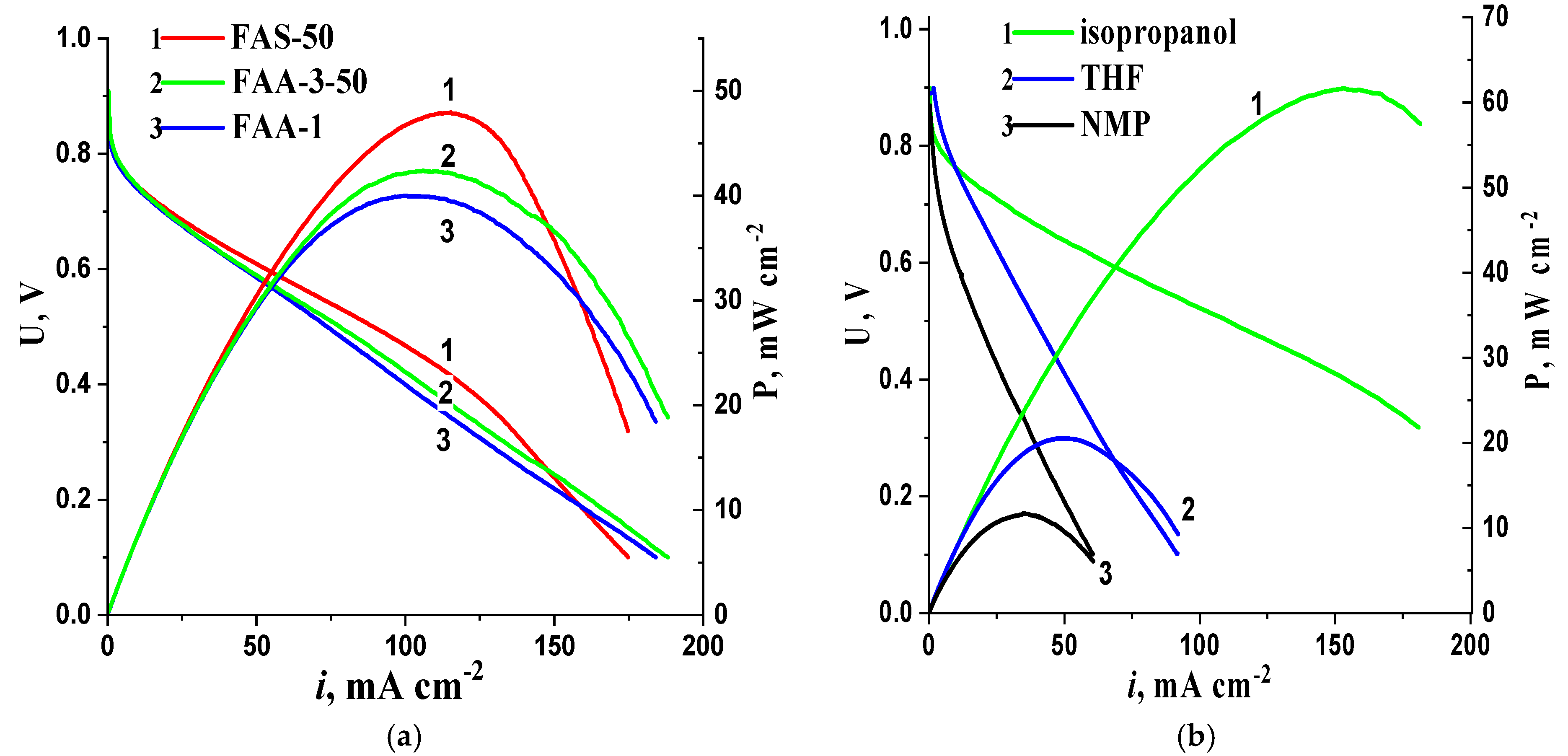
3.3. Optimization of MEA
4. Conclusions
Author Contributions
Funding
Institutional Review Board Statement
Data Availability Statement
Conflicts of Interest
References
- Firouzjaie, H.A.; Mustain, W.E. Catalytic Advantages, Challenges, and Priorities in Alkaline Membrane Fuel Cells. ACS Catal. 2020, 10, 225–234. [Google Scholar] [CrossRef] [Green Version]
- Blizanac, B.B.; Ross, P.N.; Markovic, N.M. Oxygen electroreduction on Ag (1 1 1): The pH effect. Electrochim. Acta 2007, 52, 2264–2271. [Google Scholar] [CrossRef]
- Tarasevich, M.R.; Korchagin, O.V. Electrocatalysis and pH (a review). Russ. J. Electrochem. 2013, 49, 600–618. [Google Scholar] [CrossRef]
- Shao, Y.; Dodelet, J.-P.; Wu, G.; Zelenay, P. PGM-Free Cathode Catalysts for PEM Fuel Cells: A Mini-Review on Stability Challenges. Adv. Mater. 2019, 31, 1807615. [Google Scholar] [CrossRef] [PubMed]
- Omasta, T.J.; Park, A.M.; LaManna, J.M.; Zhang, Y.; Peng, X.; Wang, L.; Jacobson, D.L.; Varcoe, J.R.; Hussey, D.S.; Pivovar, B.S.; et al. Beyond catalysis and membranes: Visualizing and solving the challenge of electrode water accumulation and flooding in AEMFCs. Energy Environ. Sci. 2018, 11, 551. [Google Scholar] [CrossRef] [Green Version]
- Zhang, J.; Zhu, W.; Huang, T.; Zheng, C.; Pei, Y.; Shen, G.; Nie, Z.; Xiao, D.; Yin, Y.; Guiver, M.D. Recent Insights on Catalyst Layers for Anion Exchange Membrane Fuel Cells. Adv. Sci. 2021, 8, 2100284. [Google Scholar] [CrossRef]
- Xue, Y.; Shi, L.; Liu, X.; Fang, J.; Wang, X.; Setzler, B.P.; Zhu, W.; Yan, Y.; Zhuang, Z. A highly-active, stable and low-cost platinum-free anode catalyst based on RuNi for hydroxide exchange membrane fuel cells. Nat. Commun. 2020, 11, 5651. [Google Scholar] [CrossRef]
- Alesker, M.; Page, M.; Shviro, M.; Paska, Y.; Gershinsky, G.; Dekel, D.R.; Zitoun, D. Palladium/nickel bifunctional electrocatalyst for hydrogen oxidation reaction in alkaline membrane fuel cell. J. Power Sources 2016, 304, 332–339. [Google Scholar] [CrossRef]
- Miller, H.A.; Bellini, M.; Dekel, D.R.; Vizza, F. Recent developments in Pd-CeO2 nano-composite electrocatalysts for anodic reactions in anion exchange membrane fuel cells. Electrochem. Commun. 2022, 135, 107219. [Google Scholar] [CrossRef]
- Doan, H.; Morais, T.; Borchtchoukova, N.; Wijsboom, Y.; Sharabi, R.; Chatenet, M.; Finkelshtain, G. Bimetallic Pt or Pd-based carbon supported nanoparticles are more stable than their monometallic counterparts for application in membraneless alkaline fuel cell anodes. Appl. Cat. B Environ. 2022, 301, 120811. [Google Scholar] [CrossRef]
- Li, F.-M.; Huang, L.; Zaman, S.; Guo, W.; Liu, H.; Guo, X.; Xia, B.Y. Corrosion Chemistry of Electrocatalysts. Adv. Mater. 2022, 34, 2200840. [Google Scholar] [CrossRef]
- Mandal, M.; Huang, G.; Hassan, N.U.; Peng, X.; Gu, T.; Brooks-Starks, A.H.; Bahar, B.; Mustain, W.E.; Kohl, P.A. The Importance of Water Transport in High Conductivity and High-Power Alkaline Fuel Cells. J. Electrochem. Soc. 2020, 167, 054501. [Google Scholar] [CrossRef]
- Bang, J.H.; Kim, H. CO-Tolerant PtMo/C Fuel Cell Catalyst for H2 Oxidation. Bull. Korean Chem. Soc. 2011, 32, 10. [Google Scholar] [CrossRef]
- Hassan, A.; Carreras, A.; Trincavelli, J.; Ticianelli, E.A. Effect of heat treatment on the activity and stability of carbon supported PtMo alloy electrocatalysts for hydrogen oxidation in proton exchange membrane fuel cells. Journal of Power Sources 2014, 247, 712–720. [Google Scholar] [CrossRef]
- Gao, J.; Zou, J.; Zeng, X.; Ding, W. Carbon supported nano Pt–Mo alloy catalysts for oxygen reduction in magnesium–air batteries. RSC Adv. 2016, 6, 83025. [Google Scholar] [CrossRef]
- Wang, L.; Peng, X.; Mustain, W.E.; Varcoe, J.R. Radiation-grafted anion-exchange membranes: The switch from low- to high-density polyethylene leads to remarkably enhanced fuel cell performance. Energy Environ. Sci. 2019, 12, 1575. [Google Scholar] [CrossRef] [Green Version]
- Das, G.; Choi, J.-H.; Nguyen, P.K.T.; Kim, D.-J.; Yoon, Y.S. Anion Exchange Membranes for Fuel Cell Application: A Review. Polymers 2022, 14, 1197. [Google Scholar] [CrossRef]
- Barnes, A.M.; Liu, B.; Buratto, S.K. Humidity-Dependent Surface Structure and Hydroxide Conductance of a Model Quaternary Ammonium Anion Exchange Membrane. Langmuir 2019, 35, 14188–14193. [Google Scholar] [CrossRef]
- Carbone, A.; Zignani, S.C.; Gatto, I.; Trocino, S.; Aricò, A.S. Assessment of the FAA3-50 polymer electrolyte in combination with a NiMn2O4 anode catalyst for anion exchange membrane water electrolysis. Int. J. Hydrogen Energy 2020, 45, 9285–9292. [Google Scholar] [CrossRef]
- De Schepper, W.; Moraru, M.D.; Jacobs, B.; Oudshoorn, M.; Helsen, J. Electrodialysis of aqueous NaCl-glycerol solutions: A phenomenological comparison of various ion exchange membranes. Sep. Purif. Technol. 2019, 217, 274–283. [Google Scholar] [CrossRef]
- Merkel, A.; Čopák, L.; Dvořák, L.; Golubenko, D.; Šeda, L. Recovery of Spent Sulphuric Acid by Diffusion Dialysis Using a Spiral Wound Module. Int. J. Mol. Sci. 2021, 22, 11819. [Google Scholar] [CrossRef]
- Sebastián, D.; Lemes, G.; Luque-Centeno, J.M.; Martínez-Huerta, M.V.; Pardo, J.I.; Lázaro, M.J. Optimization of the Catalytic Layer for Alkaline Fuel Cells Based on Fumatech Membranes and Ionomer. Catalysts 2020, 10, 1353. [Google Scholar] [CrossRef]
- Carmo, M.; Doubek, G.; Sekol, R.C.; Linardi, M.; Taylor, A.D. Development and electrochemical studies of membrane electrode assemblies for polymer electrolyte alkaline fuel cells using FAA membrane and ionomer. J. Power Sources 2013, 230, 169–175. [Google Scholar] [CrossRef]
- Britton, B.; Holdcroft, S. The Control and Effect of Pore Size Distribution in AEMFC Catalyst Layers. J. Electrochem. Soc. 2016, 163, F353–F358. [Google Scholar] [CrossRef]
- Gatto, I.; Patti, A. Carbone. Assessment of the FAA3-50 Polymer Electrolyte for Anion Exchange Membrane Fuel Cells. ChemElectroChem 2022, 10, e202201052. [Google Scholar] [CrossRef]
- Carlson, A.; Shapturenka, P.; Eriksson, B.; Lindbergh, G.; Lagergren, C.; Lindström, R.W. Electrode parameters and operating conditions influencing the performance of anion exchange membrane fuel cells. Electrochim. Acta 2018, 277, 151–160. [Google Scholar] [CrossRef]
- Bogdanovskaya, V.A.; Kuzov, A.V.; Radina, M.V.; Filimonov, V.Y.; Sudarev, G.M.; Osina, M.A. Stability against Degradation and Activity of Catalysts with Different Platinum Load Synthesized at Carbon Nanotubes. Russ. J. Electrochem. 2020, 56, 969. [Google Scholar] [CrossRef]
- Korchagin, O.; Bogdanovskaya, V.; Vernigor, I.; Radina, M.; Andreev, V. Carbon nanotubes doped with nitrogen, modified with platinum or platinum-free for alkaline H2-O2 fuel cell. Mat. Today Commun. 2022, 33, 104584. [Google Scholar] [CrossRef]
- Golubenko, D.V.; Korchagin, O.V.; Voropaeva, D.Y.; Bogdanovskaya, V.A.; Yaroslavtsev, A.B. Membranes Based on Polyvinylidene Fluoride and Radiation-Grafted Sulfonated Polystyrene and Their Performance in Proton-Exchange Membrane Fuel Cells. Polymers 2022, 14, 3833. [Google Scholar] [CrossRef]
- Chen, N.; Hu, C.; Wang, H.H.; Kim, S.P.; Kim, H.M.; Lee, W.H.; Bae, J.Y.; Park, J.H.; Lee, Y.M. Poly(Alkyl-Terphenyl Piperidinium) Ionomers and Membranes with an Outstanding Alkaline-Membrane Fuel-Cell Performance of 2.58 W cm−2. Angew. Chem. 2021, 133, 7789–7797. [Google Scholar] [CrossRef]
- Vernigor, I.; Bogdanovskaya, V.; Radina, M.; Andreev, V.; Grafov, O. PtM/CNT (M = Mo, Ni, CoCr) Electrocatalysts with Reduced Platinum Content for Anodic Hydrogen Oxidation and Cathodic Oxygen Reduction in Alkaline Electrolytes. Catalysts 2023, 13, 161. [Google Scholar] [CrossRef]
- Rheinländer, P.J.; Herranz, J.; Durst, J.; Gasteiger, H.A. Kinetics of the Hydrogen Oxidation/Evolution Reaction on Polycrystalline Platinum in Alkaline Electrolyte Reaction Order with Respect to Hydrogen Pressure. J. Electrochem. Soc. 2014, 161, 1448. [Google Scholar] [CrossRef]
- Wang, X.L.; Qu, Z.G.; Ren, G.F. Collective enhancement in hydrophobicity and electrical conductivity of gas diffusion layer and the electrochemical performance of PEMFCs. J. Power Sources 2023, 575, 233077. [Google Scholar] [CrossRef]
- Chae, J.E.; Lee, S.Y.; Yoo, S.J.; Kim, J.Y.; Jang, J.H.; Park, H.-Y.; Park, H.S.; Seo, B.; Henkensmeier, D.; Song, K.H.; et al. Polystyrene-Based Hydroxide-Ion-Conducting Ionomer: Binder Characteristics and Performance in Anion-Exchange Membrane Fuel Cells. Polymers 2021, 13, 690. [Google Scholar] [CrossRef]
- Chen, N.; Wang, H.H.; Kim, S.P.; Kim, H.M.; Lee, W.H.; Hu, C.; Bae, J.Y.; Sim, E.S.; Chung, Y.-C.; Jang, J.-H.; et al. Poly(fluorenyl aryl piperidinium) membranes and ionomers for anion exchange membrane fuel cells. Nat. Commun. 2021, 12, 2367. [Google Scholar] [CrossRef] [PubMed]
- Karuppannan, M.; Park, J.E.; Bae, H.E.; Cho, Y.-H.; Kwon, O.J. A nitrogen and fluorine enriched Fe/Fe3C@C oxygen reduction reaction electrocatalyst for anion/proton exchange membrane fuel cells. Nanoscale 2020, 12, 2542–2554. [Google Scholar] [CrossRef] [PubMed]
- Matanovic, I.; Maurya, S.; Park, E.J.; Jeon, J.Y.; Bae, C.; Kim, Y.S. Adsorption of Polyaromatic Backbone Impacts the Performance of Anion Exchange Membrane Fuel Cells. Chem. Mater. 2019, 31, 4195–4204. [Google Scholar] [CrossRef]
- Yassin, K.; Douglin, J.C.; Rasin, I.G.; Santori, P.G.; Eriksson, B.; Bibent, N.; Jaouen, F.; Brandon, S.; Dekel, D.R. The effect of membrane thickness on AEMFC Performance: An integrated theoretical and experimental study. Energy Convers. Manag. 2022, 270, 116203. [Google Scholar] [CrossRef]


| Parameter | SBET//SEASPt *, m2/g | Total Pore Volume, cm3/g | Mesopore Volume, cm3/g; (Diameter > 2 nm) | External Surface Area//Micropore Surface Area, m2/g | |
|---|---|---|---|---|---|
| Catalyst | |||||
| 10PtMo/CNTN | 167//24 | 1.87 | 1.79 | 145.7//21.4 | |
| 10PtMo/CNTN + Fumion | 108//22 | 1.00 | 0.68 | 103.9//4.3 | |
| 60Pt/CNTN | 91.1//56 | 1.03 | 0.89 | 80.2//10.9 | |
| 60Pt/CNTN + Fumion | 43.6//60 | 0.76 | 0.73 | 41.3//4.0 | |
| Catalyst | SEAS Pt, m2/g | i, mA/cm2 at 0.4 V | η, mV at 1.5 mA/cm2 |
|---|---|---|---|
| without Fumion//with Fumion | |||
| 10PtMo/CNTN | 24//22 | 2//2 | 100//100 |
| 60Pt/CNTN | 56//60 | 2.3//2.3 | 25//25 |
| Membrane/Ionomer | Cathode Catalyst, %Pt (Pt Loading, mg cm−2) | Anode Catalyst, %Pt (Pt Loading, mg cm−2) | tcell, °C | Backpressure, atm | Pmax, mW cm−2 | Ref. |
|---|---|---|---|---|---|---|
| FAA-3-20/ Fumion | 40Pt/C (0.5) | 40Pt/C (0.5) | 50 | 0.5 | 85 | [22] |
| FAA-3-50/ FAA-3 ionomer | 20Pt/C (0.5) | 20Pt/C (0.5) | 40 | 0 | 41 | [23] |
| FAA-3-20/ Fumion | 44.6Pt/C (0.5) | 44.6Pt/C (0.4) | 60 | 0 | 300–400 | [24] |
| FAA-3-20/ Fumion | 46.7Pt/C (0.4) | 46.7Pt/C (0.4) | 60 | 0 | 300 | [34] |
| FAA-3-20/ Fumion | 46.6Pt/C (0.33) | 46.6Pt/C (0.33) | 65 | With backpressure | 400–500 | [35] |
| FAA-3-50/ FAA-3 ionomer | 40Pt/C (0.5) | 40Pt/C (0.5) | 60 | 0 | 75–140 | [25] |
| FAA-3-50/ Fumion | NFC@Fe/Fe3C (0) | 40Pt/C (0.4) | 60 | 0 | 96 | [36] |
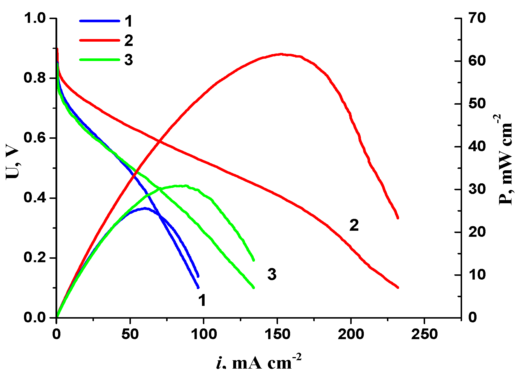
| FAA-3-50, FAS/ Fumion | CNTN (0) | 10PtMo/CNTN (0.4) | 40 | 0 | 62 | This work |
| CNTN (0) | 60Pt/CNTN (0.4) | 40 | 0 | 32 |
Disclaimer/Publisher’s Note: The statements, opinions and data contained in all publications are solely those of the individual author(s) and contributor(s) and not of MDPI and/or the editor(s). MDPI and/or the editor(s) disclaim responsibility for any injury to people or property resulting from any ideas, methods, instructions or products referred to in the content. |
© 2023 by the authors. Licensee MDPI, Basel, Switzerland. This article is an open access article distributed under the terms and conditions of the Creative Commons Attribution (CC BY) license (https://creativecommons.org/licenses/by/4.0/).
Share and Cite
Korchagin, O.; Bogdanovskaya, V.; Vernigor, I.; Radina, M.; Stenina, I.; Yaroslavtsev, A. Development of Hydrogen–Oxygen Fuel Cells Based on Anion-Exchange Electrolytes and Catalysts with Reduced Platinum Content. Membranes 2023, 13, 669. https://doi.org/10.3390/membranes13070669
Korchagin O, Bogdanovskaya V, Vernigor I, Radina M, Stenina I, Yaroslavtsev A. Development of Hydrogen–Oxygen Fuel Cells Based on Anion-Exchange Electrolytes and Catalysts with Reduced Platinum Content. Membranes. 2023; 13(7):669. https://doi.org/10.3390/membranes13070669
Chicago/Turabian StyleKorchagin, Oleg, Vera Bogdanovskaya, Inna Vernigor, Marina Radina, Irina Stenina, and Andrey Yaroslavtsev. 2023. "Development of Hydrogen–Oxygen Fuel Cells Based on Anion-Exchange Electrolytes and Catalysts with Reduced Platinum Content" Membranes 13, no. 7: 669. https://doi.org/10.3390/membranes13070669