Article

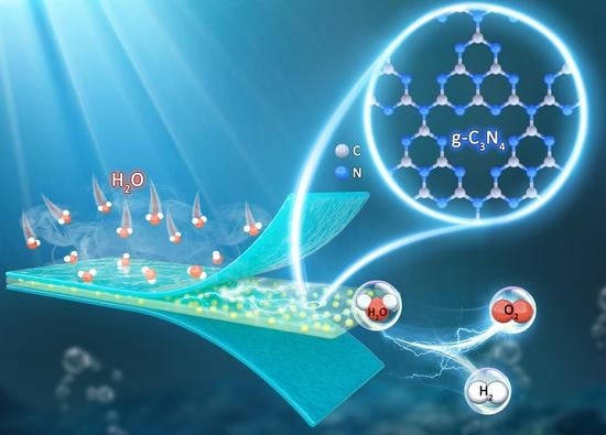
Novel Nafion/Graphitic Carbon Nitride Nanosheets Composite Membrane for Steam Electrolysis at 110 °C

1
Fuel Cell System and Engineering Laboratory, Key Laboratory of Fuel Cells & Hybrid Power Sources, Dalian Institute of Chemical Physics, Chinese Academy of Sciences, Dalian 116023, China
2
University of Chinese Academy of Sciences, Beijing 100039, China
*
Authors to whom correspondence should be addressed.
Membranes 2023, 13(3), 308; https://doi.org/10.3390/membranes13030308
Submission received: 8 February 2023 / Revised: 21 February 2023 / Accepted: 23 February 2023 / Published: 7 March 2023
(This article belongs to the Special Issue Membranes in Fuel Cell and Electrolyzer Applications)

Abstract

:
Hydrogen is expected to have an important role in future energy systems; however, further research is required to ensure the commercial viability of hydrogen generation. Proton exchange membrane steam electrolysis above 100 °C has attracted significant research interest owing to its high electrolytic efficiency and the potential to reduce the use of electrical energy through waste heat utilization. This study developed a novel composite membrane fabricated from graphitic carbon nitride (g-C3N4) and Nafion and applied it to steam electrolysis with excellent results. g-C3N4 is uniformly dispersed among the non−homogeneous functionalized particles of the polymer, and it improves the thermostability of the membranes. The amino and imino active sites on the nanosheet surface enhance the proton conductivity. In ultrapure water at 90 °C, the proton conductivity of the Nafion/0.4 wt.% g-C3N4 membrane is 287.71 mS cm−1. Above 100 °C, the modified membranes still exhibit high conductivity, and no sudden decreases in conductivity were observed. The Nafion/g-C3N4 membranes exhibit excellent performance when utilized as a steam electrolyzer. Compared with that of previous studies, this approach achieves better electrolytic behavior with a relatively low catalyst loading. Steam electrolysis using a Nafion/0.4 wt.% g-C3N4 membranes achieves a current density of 2260 mA cm−2 at 2 V, which is approximately 69% higher than the current density achieved using pure Nafion membranes under the same conditions.

Graphical Abstract

1. Introduction

Hydrogen energy is expected to be of significant importance over the next 30 years, and the global hydrogen industry is projected to be worth 10 trillion dollars by 2050 [1]. Wind and solar power are distributed energy sources, which are difficult to deploy on the grid. This is due to the intermittent and unstable nature of renewable energy, which leads to a huge gap between energy supply and consumption [2]. However, they can be used to produce hydrogen, which is an efficient energy carrier, via economical and environmentally friendly methods. Hydrogen can be produced via water electrolysis, which is nonpolluting, does not require separation operations, and can be adjusted to suit the required hydrogen−production capacity [3].
Recent studies on water electrolysis have concentrated on proton exchange membrane (PEM) electrolysis for alkaline electrolytic cells, which produce high−purity hydrogen, operate at high electrical densities, exhibit transient responses, and utilize neutral water feeds [4,5,6,7,8,9,10]. However, the performance of PEM electrolysis must be improved to facilitate widespread commercial applications. To exploit the kinetics under high−temperature conditions, PEM electrolysis should be conducted at temperatures higher than 100 °C [11,12,13,14,15,16,17]. As the temperature increases, the ohmic losses of high−temperature PEM water electrolyzers (HT−PEMWEs) and the activated losses of the electrodes are reduced. Therefore, high working temperatures may significantly reduce the overpotential of the electrolyzers and improve their electrical properties. Furthermore, as the temperature increases, the total thermodynamic energy required for water decomposition decreases, which reduces the amount of the electrical energy required. Therefore, at high temperatures, the thermal energy of the operating environment is primarily used to fulfill the activation energy requirement; therefore, this technology can utilize waste heat from industry.
Another advantage of HT−PEMWEs is that no liquid water is used in the electrolyzer, which optimizes the management of water and facilitates subsequent gas compression [18]. However, high temperatures increase the saturation pressure of water and reduce the humidity within the electrolytic cell. Therefore, PEMs may become dehydrated when operated at high temperatures, which will reduce the proton conductivity and degrade the electrochemical properties [19].
Researchers [15,18,20,21,22] have developed novel modified membranes using Nafion to address the issue of a reduced proton conductivity in membranes. There are two main improvement strategies: one is to dope inorganic or porous materials to improve the water absorption of the membrane. The other is to choose other perfluoroalkylsulfonic acid (PFSA) type membranes. Aquivion, for example, has a high softening temperature due to its short sulfonic acid side chain structure. Hansen et al. [15] applied a Nafion membrane doped with phosphoric acid in a HT−PEMWEs. In comparison to conventional perfluorosulfonic acid membranes, their membrane exhibited good thermostability and cell performance under high−temperature conditions. However, issues such as severe phosphoric acid loss and toxic effects on the catalyst remain to be resolved. Aili et al. [18] developed Nafion−blended membranes using polybenzimidazole (PBI). The phosphate absorption rate of the membranes was mainly affected by the ratio of PBI to Nafion, and it was minimized using a neutral blend. Antonucci et al. [20] employed SiO2−doped modified−Nafion membranes for steam electrolysis applications. The modified membranes performed significantly better than commercial Nafion membranes, owing to their superior water uptake abilities to that of pristine membranes. Baglio et al. [21] reported that TiO2−doped modified−Nafion membranes showed promising results in electrolytic cells operating at high temperatures. They performed better than Nafion 115, primarily because of the water−preservation properties of TiO2. There are also researchers studying other polymers to make HT−membranes. Diaz−Abad et al. [23] developed a polybenzimidazole/graphene oxide (PBI/GO) electrolyte for hybrid sulfur (HyS) cycling with a theoretical voltage of 0.16 V. Yin et al. [24] prepared phosphoric acid−doped PVC−P4VP membrane by cross−linking polyvinyl chloride (PVC) and poly(4vinylpyridine) (P4VP). Kamaroddin et al. [25,26] experimented with PBI/ZrP (zirconium phosphate) as a membrane for PEM electrolyzers. It showed higher efficiency of hydrogen production compared to Nafion 117. Park et al. [27] developed partially sulfonated poly(arylene ether sulfone) (sPAES) for the membrane. At 50% sulfonation, the electrolyte of the same thickness exhibited lower hydrogen permeation than Nafion.
Graphitic carbon nitride (g-C3N4) has the same layer−like construction as graphene material, and it is widely used in catalysts owing to its excellent thermal and hydrothermal (hydrothermal) stability and simple synthesis [28,29,30]. The g-C3N4 surface contains basic sites owing to the −amino and −imino groups. These basic sites can interact with the −SO3H group, which enhances the proton conductivity [31,32,33,34]. Several studies have investigated the properties of sulfonated poly(ether ether ketone) (SPEEK)/g-C3N4 composite membranes in vanadium oxide liquid flow batteries (VRFBs) [35,36], and the composite membranes exhibited high selectivity and low vanadium permeability. Furthermore, g-C3N4/SPEEK composite membranes have been applied to direct methanol fuel cells (DMFCs), where they improved the power density compared to that of conventional DMFCs [37]. However, the application of g-C3N4 in proton exchange membrane steam electrolysis has not been investigated.
However, no studies have applied g-C3N4 to PEM steam electrolysis. Therefore, this study aimed to prepare Nafion/g-C3N4 modified membranes by solution casting with g-C3N4 as the modified filler. The structure and physical properties of the membranes were characterized, and the mechanisms underlying the enhanced proton conductivity were investigated.

2. Materials and Methods

2.1. Materials

Sulfuric acid (95–98%, analytical reagent (AR)) was purchased from Bonuo (Dalian, China). Dicyandiamide was purchased from Macklin. Isopropanol (AR) and dimethyl sulfoxide (DMSO) were purchased from Kermel (Dalian, China). Nafion D520 ionomer was purchased from DuPont (USA).

2.2. Preparation of g-C3N4 Nanosheets

g-C3N4 was produced as shown in Figure 1. Dicyandiamide (5 g) was heated in a tube furnace from room temperature at a heating rate of 5 °C min−1 and calcined at 550 °C for 4 h under an air condition. After cooling naturally, a yellow solid was obtained. Thereafter, g-C3N4 was produced by pulverizing the resulting product into a powder [38].

2.3. Fabrication of the Nafion/g-C3N4 Membrane

The Nafion/g-C3N4 composite membranes were produced using the solvent−molding technique, as shown in Figure 1. Firstly, 100 g of Nafion D520 ionomer was vaporized at 80 °C. Thereafter, 95 g of DMSO was used to dissolve the resin to obtain a 5 wt.% Nafion solution. g-C3N4 was dispersed in 16 g of the Nafion solution and subjected to vigorous sonication. The g-C3N4 mass fraction (relative to Nafion) in the composite membranes varied from 0–1.0%. The Nafion/g-C3N4 mixtures were inverted onto recess plates and dried in an oven at 80 °C for 24 h and at 120 °C for 12 h. The samples were naturally cooled to 25 °C, and then, the modified membranes were obtained by peeling them from the plates. The membranes were immersed in 0.5 mol L−1 H2SO4 at 80 °C for 3 h, and then heated in ultrapure water at 80 °C for 1 h, which was repeated for three times. Finally, the membranes were air−dried for further study. The membranes were labeled Nafion/X wt.% g-C3N4 depending on the mass of g-C3N4 doping. The thicknesses of the composite membranes were 49−53 μm, which was similar to that of the Nafion 212 membranes (50.8 μm).

2.4. Physical Characterization

The micromorphologies of the g-C3N4 nanosheets and modified membranes were observed using transmission electron microscopy (TEM, Tecnai G2 F30) and scanning electron microscopy (SEM, SU8020). The crystal structures of g-C3N4 and the modified membranes was examined using X−ray diffraction (XRD, Empyrean−100). The chemical moieties of the g-C3N4 and modified membranes were examined using Fourier−transform infrared (FTIR) spectroscopy (Nicolet iS50). The thermal stability was examined via the thermogravimetric analysis (TGA, STA449F5) with a warming rate of 10 °C min−1 under a N2 atmosphere. The mechanical strengths of the modified membranes were examined using a universal testing machine (WDW−10).

2.5. Water Absorption and Degree of Swelling

The amount of water absorbed by a membrane can be determined by comparing its wet and dry masses. To determine the wet mass of the membrane, the membrane was first soaked in ultrapure water at 30 °C for 24 h; thereafter, the surface of the membrane was dried rapidly using filter paper before the sample was weighed. To determine the dry mass of the membrane, the membrane was dried in an oven at 80 °C for 24 h. The water absorption rate was calculated using the Equation (1):
Water   absorption   % = M wet M dry M dry × 100 %
where Mwet and Mdry are the wet and dry masses of the membrane, respectively.
To determine the degree of swelling, the dry membranes were immersed in ultrapure water for 24 h. The degree of swelling was calculated by comparing the dry and wet areas of the membranes based on the Equation (2):
Degree   of   swelling   % = A wet A dry A dry × 100 %
where Awet and Adry are the wet and dry membrane areas, respectively.

2.6. Proton Conductivity Tests

The proton conductivities of the membranes were determined via electrochemical impedance spectroscopy (EIS) with a Gamry Interface 5000E with a frequency range of 1 MHz to 1 Hz and at a measurement potential amplitude of 10 mV.
For working temperatures of 30–90 °C, the membranes were maintained at the working temperature for 20 min before the proton conductivity tests (to reduce measurement errors), and then, they were soaked in ultrapure water. The proton conductivity (σ) of these samples were determined using the Equation (3):
σ = L R W d
where L is the distance between the two electrodes; R is the resistance of the sample; W is the width of the sample; and d is the single membrane thickness.
For working temperatures of 100–120 °C, the proton conductivity in the direction of membrane penetration was tested. The uncoated catalyst membrane was sandwiched between two gas diffusion layers (GDLs) and made into a membrane electrode assembly by hot pressing. The effective area of the sample was 5 cm2. Tests were conducted at ambient pressure using the HT−PEMWE setup with a water intake of 15 cm3 min−1. The proton conductivities of these samples were determined using the Equation (4):
σ = L R A
where L is the thickness of a single membrane; R is the resistance of the sample; and A is the area of the electrode.

2.7. Electrolysis Tests

The high−temperature PEM steam electrolysis polarization curves were recorded using a custom−built electrolysis platform, as shown in Figure 2a. Steam was supplied to the anode from an evaporator at 180 °C, and the inlet air path was insulated with heating tape at 140 °C. Water was pumped into the evaporator at a rate of 15 cm3 min−1, and it evaporated completely. The electrolyzer was warmed by heating bars to the working temperature for 30 min before steam was introduced into the electrolyzer. The electrolysis tests were conducted at 110 °C and ambient pressure. The effective area of the electrolyzer is 5 cm2. Ir black was used as the anode catalyst, 70 wt.% Pt/C was used as the cathode catalyst, and Nafion was used as the binder. The Ir loading was 1.5 mg cm−2 and the Pt loading was 0.5 mg cm−2. The anode gas diffusion layer was Pt−plated Ti felt, and carbon paper was used as the cathode gas diffusion layer. Gas diffusion electrodes (GDEs) are prepared by covering the catalyst with GDLs using a spraying method. The PEM is placed between two GDEs and held in place by polyester frames, which is thermally pressed to form a membrane electrode assembly (MEA). The flow field of the bipolar plates is a parallel flow field. The cell is assembled in the structure shown in Figure 2b.

3. Results

3.1. Characterization of g-C3N4

g-C3N4 has a clear two−dimensional sheet−like morphology with minimal aggregation (Figure 3a–c). Energy−dispersive spectroscopy (EDS) analysis indicates that N is uniformly distributed throughout the g-C3N4 nanosheets (Figure 3d). The elemental composition of g-C3N4 is determined using EDS. g-C3N4 is composed mainly of C (42.98 at.%) and N (57.02 at.%) with a C/N ratio of 0.754 (approximately equal to the theoretical figure of 0.75). These results indicate the effective synthesis of g-C3N4.
The crystal structure of g-C3N4 is shown in Figure 4a. Two strong absorption peaks are observed in the g-C3N4 spectrum at 27.43° and 12.78°, which corresponded to (002) and (100) planes, respectively. These results are in agreement with those reported by Yuan et al. [39], and they indicate that g-C3N4 was successfully synthesized [35,36].
Figure 4b shows the FT−IR spectrum of g-C3N4, confirming the production of g-C3N4. The strong peak at 803 cm−1 is the signature peak of the triazine ring, and the characteristic peaks between of 1250 and 1650 cm−1 correspond to the tensile peaks of N−(C)3 and C−NH−C [40,41]. The broad peak at approximately 3156 cm−1 is associated with the defective positions of the primary and secondary amines and their intermolecular hydrogen bonding interactions [42].

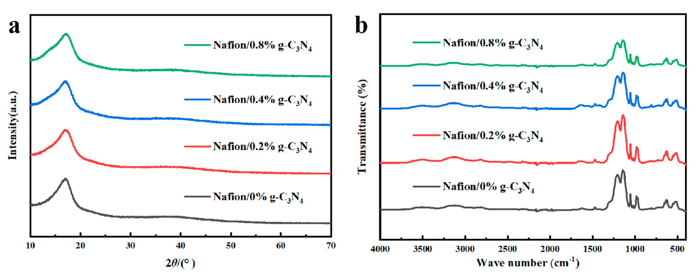
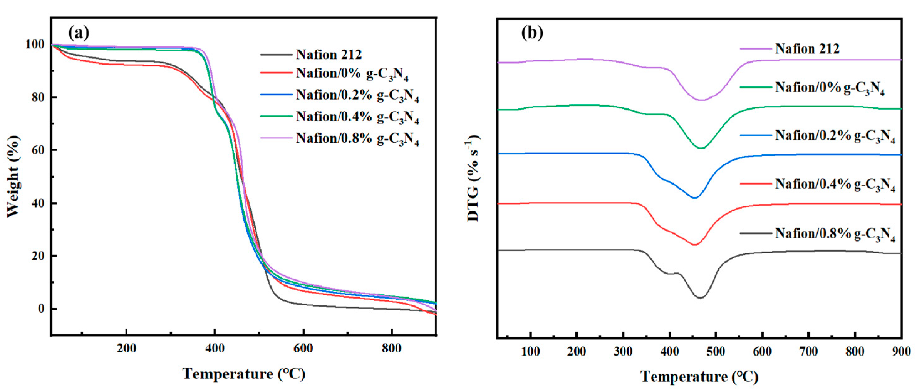
3.2. Properties of Nafion/X wt.% g-C3N4 Modified Membranes

The dispersion of g-C3N4 in Nafion is investigated using SEM, and elemental distribution is detected using EDS. g-C3N4 are evenly dispersed with negligible aggregation in Nafion, as shown in Figure 5, owing to the good surface interactions between g-C3N4 and Nafion and the large surface area of g-C3N4 [43]. Furthermore, the uniform g-C3N4 distribution enhances the tensile strength of the membrane, which was consistent with the test results for the modified membranes. Doping ratios higher than 1.0% have also been experimented. However, excessively high doping ratios can cause significant agglomeration of g-C3N4, which severely decreases the mechanical properties and homogeneity of the membrane, and even prevents the formation of the membrane.
Two peaks at 2θ ≈ 17° and 2θ ≈ 39° were present in all the modified membranes (Figure 6a). The broad peak at 2θ ≈ 17° is composed of two peaks and can be decomposed into two peaks at 2θ = 16.6° and 2θ = 17.3°. Information about the morphology of the main chain in Nafion is represented by a peak at 2θ ≈ 16° and the crystallinity of the main chain is represented by a peak at 2θ ≈ 17.5° [44]. Therefore, the XRD patterns show that the addition of g-C3N4 had negligible effects on the crystallinity of the Nafion membranes.
Figure 6b shows the FT−IR spectra of the modified membranes. For the Nafion (perfluorosulfonic acid) membranes, the typical absorption vibration peaks originate from the −SO3 group and the C−O−C groups. The stretching vibration absorption peak of −CF2−CF2 appeares at 1150 cm−1 and the typical peaks of −SO3 and C−O−C on the side chains are observed at 1056 and 982 cm−1 [45,46]. After doping with g-C3N4, the intensity of the peak between 1130 and 1250 cm−1 reduced, which may be caused by C−F···H−N hydrogen bonding.
As shown in Figure 7, doping with g-C3N4 enhances the thermostability of the modified membrane. All the membranes exhibit a typical weight−reducing pattern [47,48]. The weight loss below 140 °C occurred as residual water was lost from the membranes. Between 140–250 °C, no significant weight loss was noted, and the membranes appeared to be stable. For pure Nafion membranes, the first loss at 250–350 °C occurred owing to the disconnection of the sulfonic acid group, whereas the second loss at 380–450 °C occurred owing to side−chain degradation. By contrast, for the composite membranes, the first loss interval did not begin until 340 °C. The mass loss at 340–400 °C is mainly caused by the decomposition of the side chains. As shown in Figure 7a, the main loss interval (accounting for approximately 70% of the total loss) in all the membranes occurs above 450 °C. This loss was caused by the thermal degradation of the Teflon backbone. Derivative thermogravimetric (DTG) analysis is shown in Figure 7b. In summary, the acid–base interaction between g-C3N4 and Nafion improves the thermostability of the modified membranes compared to that of the pure Nafion membrane [49].

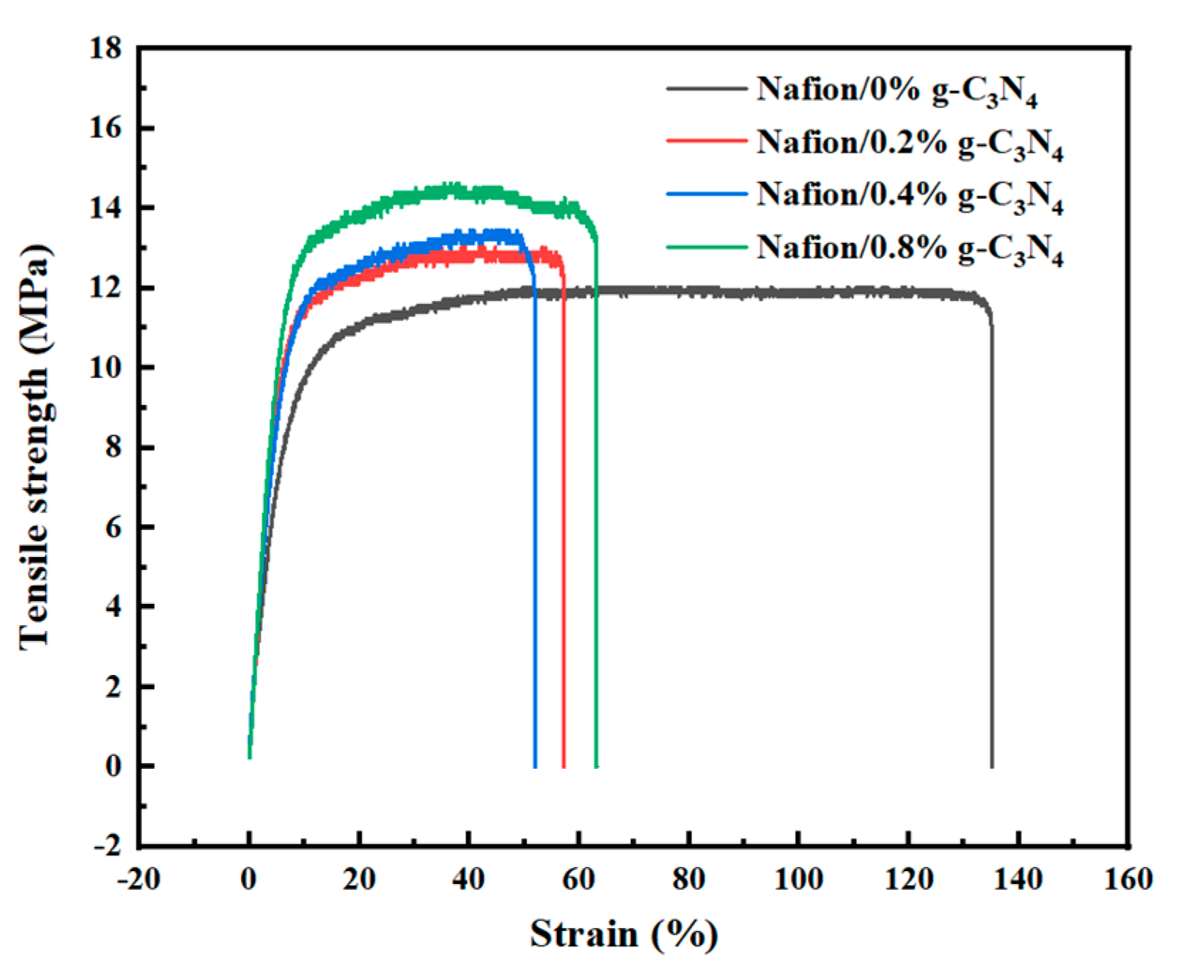
3.3. Water Absorption, Swelling Degree, and Mechanical Properties

Appropriate water absorption can enhance the proton conductivity of the membranes and facilitate electrolysis at high temperatures. As presented in Table 1, g-C3N4 doping significantly increases the amount of water absorbed by the membranes, which occurs because of the strong attraction between g-C3N4 and the water molecules. The water absorption rate of the composite membrane with 0.8 wt.% doping is 30.65%, which is approximately 74% higher than that of pure Nafion. The increased g-C3N4 content is expected to form larger ion clusters and produce more hydrogen bonds, which can enhance proton transport.
The mechanical properties of the membranes are listed in Table 1. The addition of g-C3N4 increases the mechanical stability. As shown in Figure 8, the elongation at the breaking point of the pure Nafion membrane is 135.15%, and the tensile strength is 12.03 MPa. By comparison, the modified membranes had a higher tensile strength and lower elongation at the breaking point. The Nafion/0.8% g-C3N4 membrane has the highest tensile strength of 14.63 MPa, which is approximately 22% higher than that of pure Nafion. The test results indicate that g-C3N4 doping can be used to enhance the mechanical properties of the membrane.

3.4. Proton Conductivity

Proton conductivity is an important characteristic that determines the electrolytic properties of the membranes; therefore, it is evaluated using EIS. The proton conductivities of the Nafion/g-C3N4 modified membranes are higher than those of pure Nafion (Figure 9a). In particular, the Nafion/0.4% g-C3N4 membrane has the highest proton conductivity of 287.71 mS cm−1 at 90 °C, which is approximately 89% higher than that of the pure Nafion. This may be because the modified membranes absorbed more water, which formed proton transport channels. However, the proton conductivity of the Nafion/0.8% g-C3N4 membrane decreased, probably because the excess g-C3N4 blocked some of the proton transport channels. Above 100 °C, the relative humidity is low, even when the water vapor feed was at its highest, which reduced the conductivity of the membrane. However, the modified membranes exhibited higher conductivity and did not exhibit abrupt decreases in conductivity at high temperatures (Figure 9b). This indicates that the strong water absorption of g-C3N4 effectively improves the membrane performance under low humidity conditions. The tests above 100 °C are performed at ambient pressure. Therefore, further improvements in the device to allow testing under pressurized conditions may reveal a significant increase in performance.

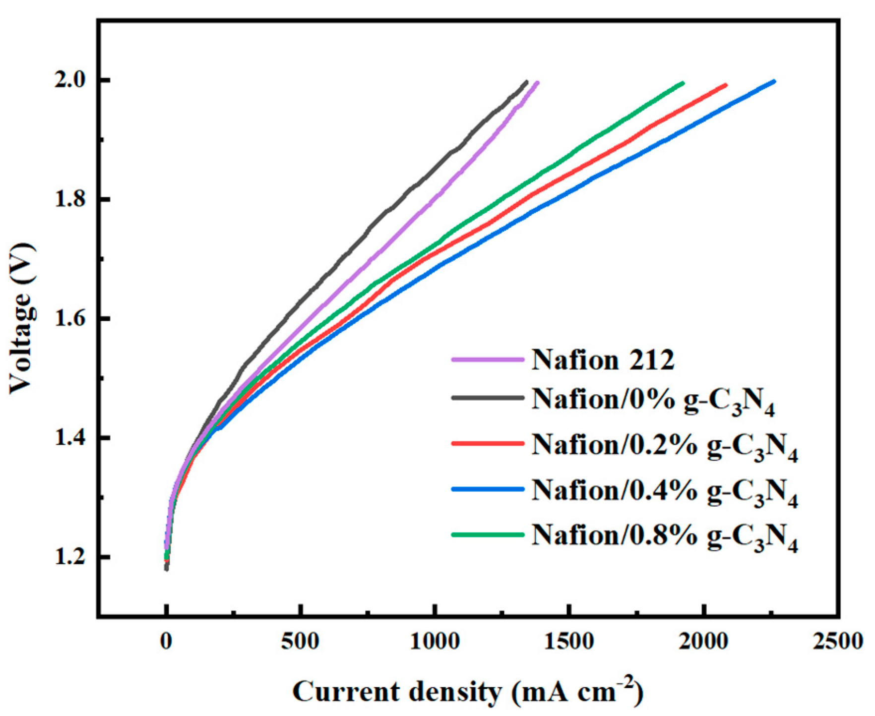
3.5. Electrolysis Performance

The steam electrolysis performances of the Nafion/g-C3N4 modified membranes were measured, and the results are shown in Figure 10. At low current densities, the electrolysis voltages of the different membranes were approximately the same, suggesting that they had the same catalytic properties and that the differences in their electrolytic performances were caused by their different conductivities. The commercial Nafion 212 membrane shows approximately the same results as the pure Nafion membrane that we produced. This indicates that the improvement in the electrolytic performance is derived from the addition of g-C3N4. At 2.0 V, the optimal peak current density of the Nafion/0.4% g-C3N4 and pure−Nafion membranes are 2260 and 1340 mA cm−2, respectively. At a current density of 1000 mA cm−2, the Nafion/0.4 %g-C3N4 membrane has the lowest electrolysis voltage of 1.684 V. The results suggest that doping with g-C3N4 facilitates electrolysis, which is attributed to the higher proton conductivity of the modified membranes than that of the pure−Nafion membranes. Table 2 lists the high−temperature PEM electrolysis performance of the Nafion/0.4% g-C3N4 membrane produced in this study compared to the results obtained in other studies. The Nafion/g-C3N4 membrane exhibits better electrolytic behavior with a relatively low catalyst loading, which demonstrates the superiority of Nafion/g-C3N4 modified membranes.

4. Conclusions

In this study, a strategy for preparing Nafion−composite membranes using g-C3N4 as a filler is developed. The prepared membranes achieve excellent results when utilized as steam electrolytic PEMs. Observations of the microscopic morphology reveal that the g-C3N4 is uniformly distributed in the Nafion, which resulted in a high proton conductivity and good mechanical properties. TGA reveal that the addition of g-C3N4 enhances the thermostability of the membranes. At 90 °C, the highest proton conductivity of the Nafion/0.4% g-C3N4 membrane is 287.71 mS cm−1 compared to 151.86 mS cm−1 for pure Nafion. At temperatures higher than 100 °C, the modified membranes exhibit high conductivity, and no abrupt decreases in conductivity are observed. Compared to the materials developed in previous studies, the membranes in this study demonstrated a better electrolytic performance with relatively low catalyst loading. At 2.0 V, the optimum peak current density of the Nafion/0.4% g-C3N4 membrane is 2260 mA cm−2, which is approximately 69% higher than that of pure Nafion (1340 mA cm−2). Overall, these results indicate that Nafion/g-C3N4 membranes have considerable potential for practical applications in PEM steam electrolysis.

Author Contributions

T.C.: methodology, validation, formal analysis, investigation, data curation, writing—original draft. B.L.: methodology. S.S.: writing—review and editing, supervision. J.H.: writing—review and editing, funding acquisition. Z.S.: resources, writing—review and editing, supervision, funding acquisition. All authors have read and agreed to the published version of the manuscript.

Funding

This work was financially supported by the Dalian Science and Technology Innovation Fund (No. 2021JJ11CG003) and the DICP (Dalian Institute of Chemical Physics) (Grant: DICP I202233).

Institutional Review Board Statement

Not applicable.

Data Availability Statement

Data available on request due to restrictions. The data presented in this study are available on request from the corresponding author.

Conflicts of Interest

The authors declare no conflict of interest.

References

  1. Hosseini, S.E.; Wahid, M.A. Hydrogen production from renewable and sustainable energy resources: Promising green energy carrier for clean development. Renew. Sustain. Energy Rev. 2016, 57, 850–866. [Google Scholar] [CrossRef]
  2. Zhang, H.; Sun, C.; Ge, M. Review of the Research Status of Cost−Effective Zinc–Iron Redox Flow Batteries. Batteries 2022, 8, 202. [Google Scholar] [CrossRef]
  3. Ge, Z.; Shehzad, M.A.; Yang, X.; Li, G.; Wang, H.; Yu, W.; Liang, X.; Ge, X.; Wu, L.; Xu, T. High−performance bipolar membrane for electrochemical water electrolysis. J. Membr. Sci. 2022, 656, 120660. [Google Scholar] [CrossRef]
  4. Grigoriev, S.A.; Porembsky, V.I.; Fateev, V.N. Pure hydrogen production by PEM electrolysis for hydrogen energy. Int. J. Hydrog. Energy 2006, 31, 171–175. [Google Scholar] [CrossRef]
  5. Carmo, M.; Fritz, D.L.; Mergel, J.; Stolten, D. A comprehensive review on PEM water electrolysis. Int. J. Hydrog. Energy 2013, 38, 4901–4934. [Google Scholar] [CrossRef]
  6. Wang, M.; Wang, Z.; Gong, X.; Guo, Z. The intensification technologies to water electrolysis for hydrogen production—A review. Renew. Sustain. Energy Rev. 2014, 29, 573–588. [Google Scholar] [CrossRef]
  7. Tijani, A.S.; Rahim, A.H.A. Numerical Modeling the Effect of Operating Variables on Faraday Efficiency in PEM Electrolyzer. Procedia Technol. 2016, 26, 419–427. [Google Scholar] [CrossRef] [Green Version]
  8. Santos, K.G.D.; Eckert, C.; de Rossi, E.; Bariccatti, R.A.; Frigo, E.P.; Lindino, C.A.; Alves, H.J. Hydrogen production in the electrolysis of water in Brazil, a review. Renew. Sustain. Energy Rev. 2017, 68, 563–571. [Google Scholar] [CrossRef]
  9. Buttler, A.; Spliethoff, H. Current status of water electrolysis for energy storage, grid balancing and sector coupling via power−to−gas and power−to−liquids: A review. Renew. Sustain. Energy Rev. 2018, 82, 2440–2454. [Google Scholar] [CrossRef]
  10. Corti, H.R. Polymer electrolytes for low and high temperature PEM electrolyzers. Curr. Opin. Electrochem. 2022, 36, 101109. [Google Scholar] [CrossRef]
  11. Linkous, C.A.; Anderson, H.R.; Kopitzke, R.W.; Nelson, G.L. Development of new proton exchange membrane electrolytes for water electrolysis at higher temperatures. Int. J. Hydrog. Energy 1998, 23, 525–529. [Google Scholar] [CrossRef]
  12. Nikiforov, A.V.; Tomás García, A.L.; Petrushina, I.M.; Christensen, E.; Bjerrum, N.J. Preparation and study of IrO2/SiC–Si supported anode catalyst for high temperature PEM steam electrolysers. Int. J. Hydrog. Energy 2011, 36, 5797–5805. [Google Scholar] [CrossRef]
  13. Nikiforov, A.V.; Petrushina, I.M.; Christensen, E.; Alexeev, N.V.; Samokhin, A.V.; Bjerrum, N.J. WC as a non−platinum hydrogen evolution electrocatalyst for high temperature PEM water electrolysers. Int. J. Hydrog. Energy 2012, 37, 18591–18597. [Google Scholar] [CrossRef]
  14. Aleksey, N.; Erik, C.; Irina, P.; Jens Oluf, J.; Niels, J.B. Advanced Construction Materials for High Temperature Steam PEM Electrolysers. In Electrolysis; Vladimir, L., Janis, K., Eds.; IntechOpen: Rijeka, Croatia, 2012. [Google Scholar]
  15. Hansen, M.K. PEM Water Electrolysis at Elevated Temperatures; Department of Energy Conversion and Storage, Technical University of Denmark: Kongens Lyngby, Denmark, 2012. [Google Scholar]
  16. Ge, X.; Zhang, F.; Wu, L.; Yang, Z.; Xu, T. Current Challenges and Perspectives of Polymer Electrolyte Membranes. Macromolecules 2022, 55, 3773–3787. [Google Scholar] [CrossRef]
  17. Ran, J.; Wu, L.; He, Y.; Yang, Z.; Wang, Y.; Jiang, C.; Ge, L.; Bakangura, E.; Xu, T. Ion exchange membranes: New developments and applications. J. Membr. Sci. 2017, 522, 267–291. [Google Scholar] [CrossRef]
  18. Aili, D.; Hansen, M.K.; Pan, C.; Li, Q.; Christensen, E.; Jensen, J.O.; Bjerrum, N.J. Phosphoric acid doped membranes based on Nafion®, PBI and their blends—Membrane preparation, characterization and steam electrolysis testing. Int. J. Hydrog. Energy 2011, 36, 6985–6993. [Google Scholar] [CrossRef]
  19. Bose, S.; Kuila, T.; Nguyen, T.X.H.; Kim, N.H.; Lau, K.-t.; Lee, J.H. Polymer membranes for high temperature proton exchange membrane fuel cell: Recent advances and challenges. Prog. Polym. Sci. 2011, 36, 813–843. [Google Scholar] [CrossRef]
  20. Antonucci, V.; Di Blasi, A.; Baglio, V.; Ornelas, R.; Matteucci, F.; Ledesma−Garcia, J.; Arriaga, L.G.; Aricò, A.S. High temperature operation of a composite membrane−based solid polymer electrolyte water electrolyser. Electrochim. Acta 2008, 53, 7350–7356. [Google Scholar] [CrossRef]
  21. Baglio, V.; Ornelas, R.; Matteucci, F.; Martina, F.; Ciccarella, G.; Zama, I.; Arriaga, L.G.; Antonucci, V.; Aricò, A.S. Solid Polymer Electrolyte Water Electrolyser Based on Nafion−TiO2 Composite Membrane for High Temperature Operation. Fuel Cells 2009, 9, 247–252. [Google Scholar] [CrossRef]
  22. Xu, W.; Scott, K.; Basu, S. Performance of a high temperature polymer electrolyte membrane water electrolyser. J. Power Sources 2011, 196, 8918–8924. [Google Scholar] [CrossRef]
  23. Diaz−Abad, S.; Fernández−Mancebo, S.; Rodrigo, M.A.; Lobato, J. Characterization of PBI/Graphene Oxide Composite Membranes for the SO2 Depolarized Electrolysis at High Temperature. Membranes 2022, 12, 116. [Google Scholar] [CrossRef] [PubMed]
  24. Yin, Y.; Ying, Y.; Liu, G.; Chen, H.; Fan, J.; Li, Z.; Wang, C.; Guo, Z.; Zeng, G. High Proton−Conductive and Temperature−Tolerant PVC−P4VP Membranes towards Medium−Temperature Water Electrolysis. Membranes 2022, 12, 363. [Google Scholar] [CrossRef]
  25. Kamaroddin, M.F.A.; Sabli, N.; Nia, P.M.; Abdullah, T.A.T.; Abdullah, L.C.; Izhar, S.; Ripin, A.; Ahmad, A. Phosphoric acid doped composite proton exchange membrane for hydrogen production in medium−temperature copper chloride electrolysis. Int. J. Hydrog. Energy 2020, 45, 22209–22222. [Google Scholar] [CrossRef]
  26. Ahmad Kamaroddin, M.F.; Sabli, N.; Tuan Abdullah, T.A.; Siajam, S.I.; Abdullah, L.C.; Abdul Jalil, A.; Ahmad, A. Membrane−Based Electrolysis for Hydrogen Production: A Review. Membranes 2021, 11, 810. [Google Scholar] [CrossRef] [PubMed]
  27. Park, J.E.; Kim, J.; Han, J.; Kim, K.; Park, S.; Kim, S.; Park, H.S.; Cho, Y.-H.; Lee, J.-C.; Sung, Y.-E. High−performance proton−exchange membrane water electrolysis using a sulfonated poly(arylene ether sulfone) membrane and ionomer. J. Membr. Sci. 2021, 620, 118871. [Google Scholar] [CrossRef]
  28. Wang, Y.; Wang, X.; Antonietti, M. Polymeric Graphitic Carbon Nitride as a Heterogeneous Organocatalyst: From Photochemistry to Multipurpose Catalysis to Sustainable Chemistry. Angew. Chem. Int. Ed. 2012, 51, 68–89. [Google Scholar] [CrossRef]
  29. Zheng, Y.; Liu, J.; Liang, J.; Jaroniec, M.; Qiao, S.Z. Graphitic carbon nitride materials: Controllable synthesis and applications in fuel cells and photocatalysis. Energy Environ. Sci. 2012, 5, 6717–6731. [Google Scholar] [CrossRef]
  30. Cao, S.; Low, J.; Yu, J.; Jaroniec, M. Polymeric Photocatalysts Based on Graphitic Carbon Nitride. Adv. Mater. 2015, 27, 2150–2176. [Google Scholar] [CrossRef]
  31. Zhu, J.; Xiao, P.; Li, H.; Carabineiro, S.A. Graphitic carbon nitride: Synthesis, properties, and applications in catalysis. ACS Appl. Mater. Interfaces 2014, 6, 16449–16465. [Google Scholar] [CrossRef]
  32. Zhang, Y.; Mori, T.; Niu, L.; Ye, J. Non−covalent doping of graphitic carbon nitride polymer with graphene: Controlled electronic structure and enhanced optoelectronic conversion. Energy Environ. Sci. 2011, 4, 4517–4521. [Google Scholar] [CrossRef]
  33. Miller, T.S.; Jorge, A.B.; Suter, T.M.; Sella, A.; Corà, F.; McMillan, P.F. Carbon nitrides: Synthesis and characterization of a new class of functional materials. Phys. Chem. Chem. Phys. 2017, 19, 15613–15638. [Google Scholar] [CrossRef] [PubMed] [Green Version]
  34. Mansor, N.; Miller, T.S.; Dedigama, I.; Jorge, A.B.; Jia, J.; Brázdová, V.; Mattevi, C.; Gibbs, C.; Hodgson, D.; Shearing, P.R.; et al. Graphitic Carbon Nitride as a Catalyst Support in Fuel Cells and Electrolyzers. Electrochim. Acta 2016, 222, 44–57. [Google Scholar] [CrossRef] [Green Version]
  35. Niu, R.; Kong, L.; Zheng, L.; Wang, H.; Shi, H. Novel graphitic carbon nitride nanosheets/sulfonated poly(ether ether ketone) acid−base hybrid membrane for vanadium redox flow battery. J. Membr. Sci. 2017, 525, 220–228. [Google Scholar] [CrossRef]
  36. Wang, F.; Wang, G.; Zhang, J.; Li, B.; Zhang, J.; Deng, J.; Chen, J.; Wang, R. Novel sulfonated poly(ether ether ketone)/oxidized g−C3N4 composite membrane for vanadium redox flow battery applications. J. Electroanal. Chem. 2017, 797, 107–112. [Google Scholar] [CrossRef]
  37. Gang, M.; He, G.; Li, Z.; Cao, K.; Li, Z.; Yin, Y.; Wu, H.; Jiang, Z. Graphitic carbon nitride nanosheets/sulfonated poly(ether ether ketone) nanocomposite membrane for direct methanol fuel cell application. J. Membr. Sci. 2016, 507, 1–11. [Google Scholar] [CrossRef]
  38. Lu, X.; Xu, K.; Chen, P.; Jia, K.; Liu, S.; Wu, C. Facile one step method realizing scalable production of g-C3N4nanosheets and study of their photocatalytic H2evolution activity. J. Mater. Chem. A 2014, 2, 18924–18928. [Google Scholar] [CrossRef]
  39. Yuan, B.; Chu, Z.; Li, G.; Jiang, Z.; Hu, T.; Wang, Q.; Wang, C. Water−soluble ribbon−like graphitic carbon nitride (g-C3N4): Green synthesis, self−assembly and unique optical properties. J. Mater. Chem. C 2014, 2, 8212–8215. [Google Scholar] [CrossRef]
  40. Kim, M.; Hwang, S.; Yu, J.-S. Novel ordered nanoporous graphitic C3N4 as a support for Pt–Ru anode catalyst in direct methanol fuel cell. J. Mater. Chem. 2007, 17, 1656–1659. [Google Scholar] [CrossRef]
  41. Guo, Y.; Chen, J. Photo−induced reduction of biomass−derived 5−hydroxymethylfurfural using graphitic carbon nitride supported metal catalysts. RSC Adv. 2016, 6, 101968–101973. [Google Scholar] [CrossRef]
  42. Tonda, S.; Kumar, S.; Kandula, S.; Shanker, V. Fe−doped and −mediated graphitic carbon nitride nanosheets for enhanced photocatalytic performance under natural sunlight. J. Mater. Chem. A 2014, 2, 6772–6780. [Google Scholar] [CrossRef]
  43. Lv, B.; Geng, K.; Yin, H.; Yang, C.; Hao, J.; Luan, Z.; Huang, Z.; Qin, X.; Song, W.; Li, N.; et al. Polybenzimidazole/cerium dioxide/graphitic carbon nitride nanosheets for high performance and durable high temperature proton exchange membranes. J. Membr. Sci. 2021, 639, 119760. [Google Scholar] [CrossRef]
  44. Ke, C.-C.; Li, X.-J.; Shen, Q.; Qu, S.-G.; Shao, Z.-G.; Yi, B.-L. Investigation on sulfuric acid sulfonation of in−situ sol–gel derived Nafion/SiO2 composite membrane. Int. J. Hydrog. Energy 2011, 36, 3606–3613. [Google Scholar] [CrossRef]
  45. Yu, J.; Yi, B.; Xing, D.; Liu, F.; Shao, Z.; Fu, Y.; Zhang, H. Degradation mechanism of polystyrene sulfonic acid membrane and application of its composite membranes in fuel cells. Phys. Chem. Chem. Phys. 2003, 5, 611–615. [Google Scholar] [CrossRef]
  46. Liu, F.; Yi, B.; Xing, D.; Yu, J.; Zhang, H. Nafion/PTFE composite membranes for fuel cell applications. J. Membr. Sci. 2003, 212, 213–223. [Google Scholar] [CrossRef]
  47. Zhang, Z.; Désilets, F.; Felice, V.; Mecheri, B.; Licoccia, S.; Tavares, A.C. On the proton conductivity of Nafion–Faujasite composite membranes for low temperature direct methanol fuel cells. J. Power Sources 2011, 196, 9176–9187. [Google Scholar] [CrossRef] [Green Version]
  48. Di Palma, L.; Bavasso, I.; Sarasini, F.; Tirillò, J.; Puglia, D.; Dominici, F.; Torre, L. Synthesis, characterization and performance evaluation of Fe3O4/PES nano composite membranes for microbial fuel cell. Eur. Polym. J. 2018, 99, 222–229. [Google Scholar] [CrossRef]
  49. Velayutham, P.; Sahu, A.K. Graphitic Carbon Nitride Nanosheets—Nafion as a Methanol Barrier Hybrid Membrane for Direct Methanol Fuel Cells. J. Phys. Chem. C 2018, 122, 21735–21744. [Google Scholar] [CrossRef]
  50. Hansen, M.K.; Aili, D.; Christensen, E.; Pan, C.; Eriksen, S.; Jensen, J.O.; von Barner, J.H.; Li, Q.; Bjerrum, N.J. PEM steam electrolysis at 130 °C using a phosphoric acid doped short side chain PFSA membrane. Int. J. Hydrog. Energy 2012, 37, 10992–11000. [Google Scholar] [CrossRef]
Figure 1. Schematic of the material preparation process.
Membranes 13 00308 g001
Figure 2. Schematic of (a) the HT−PEMWE setup and (b) cell structure.
Membranes 13 00308 g002
Figure 3. (a) TEM image, (b,c) SEM images, and (d) N elemental distribution in the same region of a g-C3N4 sample.
Membranes 13 00308 g003
Figure 4. (a) XRD and (b) FT−IR profiles of the g-C3N4 nanosheets.
Membranes 13 00308 g004
Figure 5. (a) Cross−sectional morphology, (b) surface morphology, (c) C distribution, and (d) N distribution in the same region of the Nafion/1.0 wt.% g-C3N4 modified membrane.
Membranes 13 00308 g005
Figure 6. (a) XRD and (b) FT−IR profiles of the Nafion/g-C3N4 modified membranes.
Membranes 13 00308 g006
Figure 7. (a) TGA and (b) DTG diagrams of Nafion/g-C3N4 modified membranes.
Membranes 13 00308 g007
Figure 8. Stress−strain curves for the Nafion/g-C3N4 modified membranes.
Membranes 13 00308 g008
Figure 9. Proton conductivity of the Nafion/g-C3N4 modified membranes at (a) 30–90 °C and (b) 100–120 °C.
Membranes 13 00308 g009
Figure 10. Steam electrolysis performance of the Nafion/g-C3N4 modified membranes at 110 °C.
Membranes 13 00308 g010
Table 1. Water absorption, degree of swelling, and mechanical properties of the Nafion/ g-C3N4 modified membranes.
MembranesWater Absorption (%)Degree of Swelling (%)Tensile Strength (MPa)Elongation at Break (%)
Nafion/0% g-C3N417.6115.5012.03135.15
Nafion/0.2% g-C3N421.8816.8813.0257.20
Nafion/0.4% g-C3N426.8718.2513.4452.06
Nafion/0.8% g-C3N430.6523.6314.6363.20
Table 2. Comparison of the steam electrolysis performance of various membrane materials.
MembranesPeak Current Density (A cm−2)Anode Catalyst Quantity (mg cm−2)Operating Temperature (°C)Reference
Nafion/0.4% g-C3N42.26 @2 V1.5110This study
Nafion 2121.38 @2 V1.5110This study
Nafion/PA0.3 @1.75 V4130[18]
PBI/PA0.5 @1.75 V4130[18]
Nafion−SiO21.18 @1.9 V5110[20]
Nafion−TiO20.7 @1.8 V5120[21]
Aquivion/PA0.775 @1.8 V1130[50]
Disclaimer/Publisher’s Note: The statements, opinions and data contained in all publications are solely those of the individual author(s) and contributor(s) and not of MDPI and/or the editor(s). MDPI and/or the editor(s) disclaim responsibility for any injury to people or property resulting from any ideas, methods, instructions or products referred to in the content.

