Article

Hydrogen Purification from Compact Palladium Membrane Module Using a Low Temperature Diffusion Bonding Technology

1
Department of Chemical and Biological Engineering, Korea University, 145 Anam-ro, Seoul 02841, Korea
2
Energy Conversion & Storage Materials Laboratory, Korea Institute of Energy Research, 152 Gajeong-ro, Daejeon 34129, Korea
*
Author to whom correspondence should be addressed.
Membranes 2020, 10(11), 338; https://doi.org/10.3390/membranes10110338
Submission received: 15 October 2020 / Revised: 28 October 2020 / Accepted: 9 November 2020 / Published: 12 November 2020

Abstract

:
This study investigates a compact palladium membrane module (CPMM) for hydrogen purification, assembled by diffusion bonding at a low-temperature (450 °C). This CPMM resulted in hydrogen (H2) flux of 18.3 mL cm−2 min−1 with H2/N2 selectivity of over 1100. The H2 purification test using a 60% H2/40% CO2 mixed gas confirmed that the CPMM can separate H2 with a concentration of more than 99%, with a pressure difference of 5 bar. Moreover, the volume of the diffusion bonded membrane module is decreased by 81.4% than the flame-type membrane module pre-studied in our laboratory.

1. Introduction

High-purity H2 gas is required for many chemical, industrial, and electronic applications such as ammonia production, steel and glass manufacture, and electrical generator cooling, respectively. Since it is nontoxic and an efficient fuel source, H2 is considered a clean energy carrier [1,2]. Fuel cell systems also require high-purity H2 for portable power. Consequently, the demand for high-purity H2 is increasing [3,4].
Hydrogen can be produced from fossil fuels by thermochemical processes like steam reforming of natural gas and by various water-splitting methods, e.g., thermochemical, photo-electro-chemical, photo-biological, and electrolysis. Over 95% of H2 gas is produced from fossil fuels [5]. Hydrogen production from fossil fuels typically comprises four steps: Desulfurization, high-temperature shift reaction, low-temperature shift reaction, and H2 purification [6,7]. The produced hydrogen can be purified via pressure swing adsorption (PSA), cryogenic distillation, and membrane separation. Among these, the PSA and cryogenic distillation methods are commercially available [8,9]. However, they are both intensive in terms of technical expertise, energy, and infrastructure requirements during operation [10,11]. The membrane separation technique has relatively low energy and cost requirements during operation. Furthermore, palladium membranes are excellent for H2 separation and purification because of their high permeability and high selectivity for H2 [11,12,13]. The hydrogen separation mechanism of the palladium membrane is basically depending on the hydrogen partial pressure. The Hydrogen molecules were dissociated into hydrogen atoms at the surface of the palladium membrane, and then diffusion into the palladium membrane. The separated hydrogen atoms through the membrane were recombined with hydrogen molecules on the opposite surface [14].
When using palladium based dense membranes, the design and configuration of the membrane module are critical for successful application in H2 separation and purification. In particular, the configuration of compact modules is necessary in small-scale H2 purification. Membrane modules can be divided into the several types depending on the membrane shape, e.g., flange [15,16,17] and tubular [11,13,15,18,19] modules. Though it may be easy to scale-up these membrane modules, ensuring compact module configuration poses difficulty.
Micro channel reactors (MCRs) are advantageous in terms of their considerable heat and mass transfer, large surface-area-to-volume ratio, compactness, and easy integration [20]. This paper reports for the first time the application of an MCR in configuring a compact and multi-stackable membrane module. For this purpose, it is vital to examine the methods for effectively assembling stainless steel (SS) components to prepare the MCR module. Typically, diffusion bonding was performed at a high-temperature (>1000 °C) using 316L SS in order to obtain a compact palladium membrane module (CPMM) [21]. However, because of the exposure of the CPMM to the harsh conditions of high-temperature and high vacuum, defects can be generated within the palladium membrane during its preparation. Therefore, the plate surfaces were modified such that the diffusion bonding could be performed at a low-temperature (450 °C) to ensure minimum damage to the palladium membrane. The module performance test was performed to determine the feasibility of the CPMM. The above-mentioned H2 separation and purification modules has disadvantages in terms of scale-up and compactness due to their complicated structure and design. accordingly, we designed an MCR type H2 separation and purification module to provide easy assembly and compact with diffusion bonding technology.

2. Materials and Method

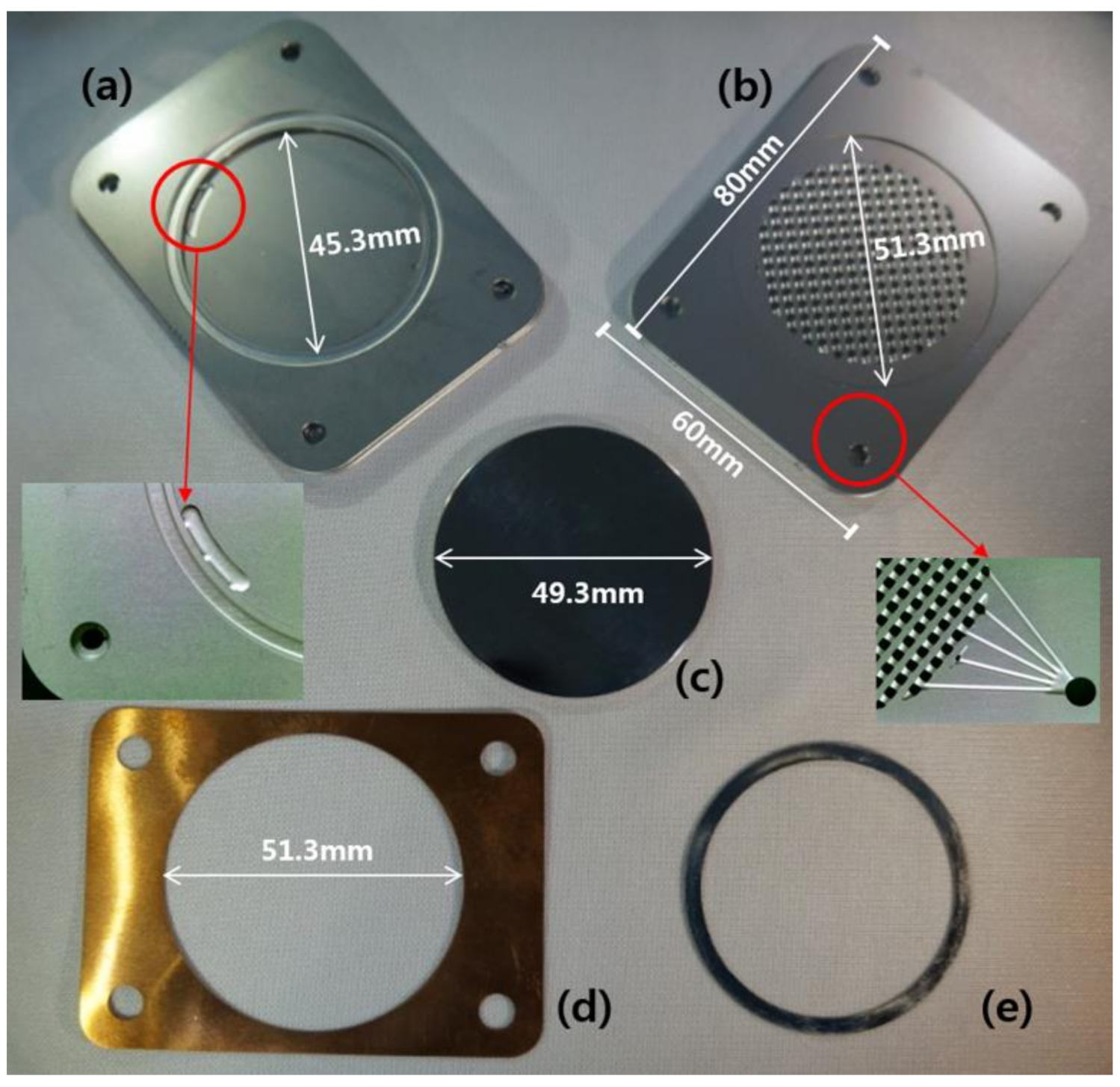
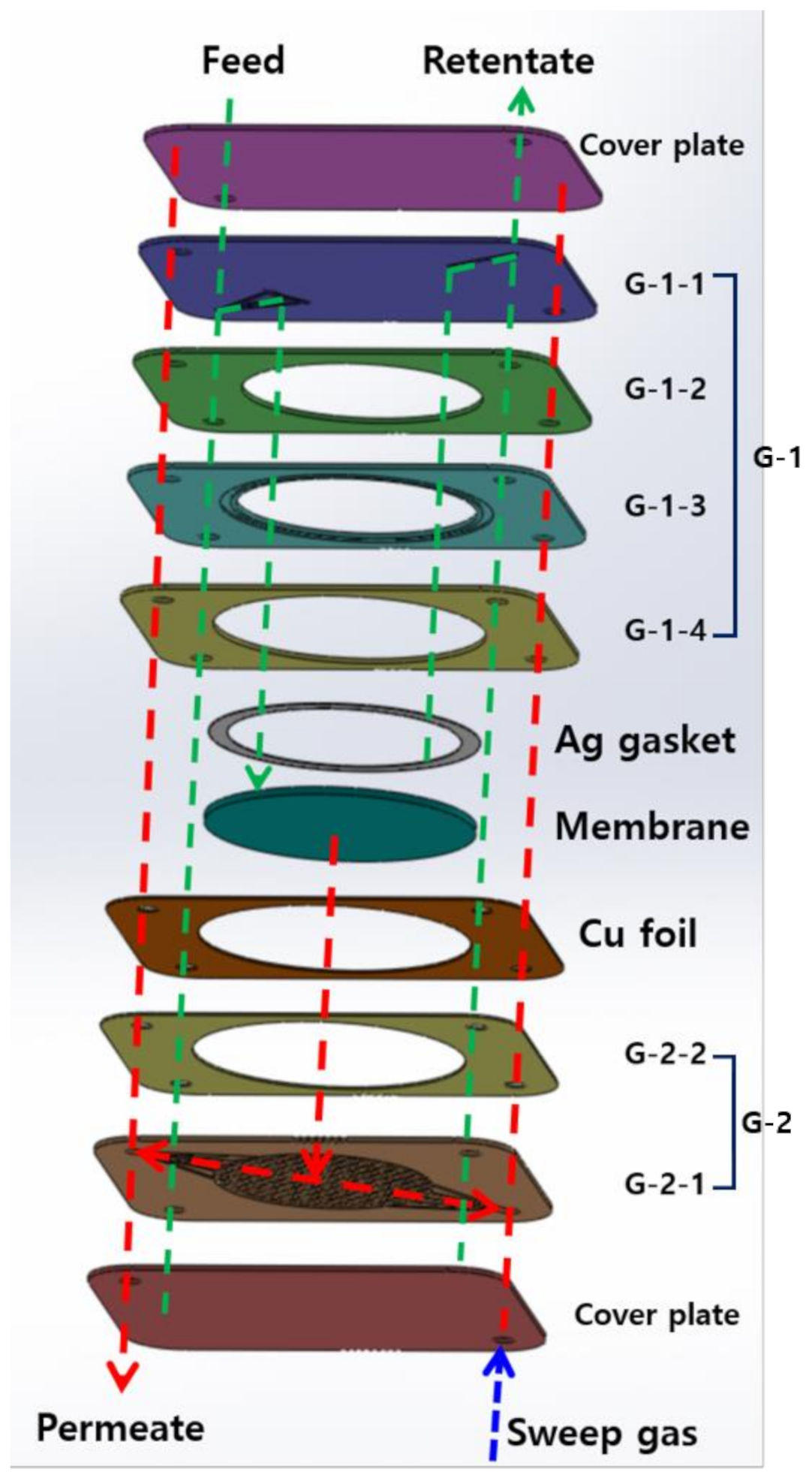
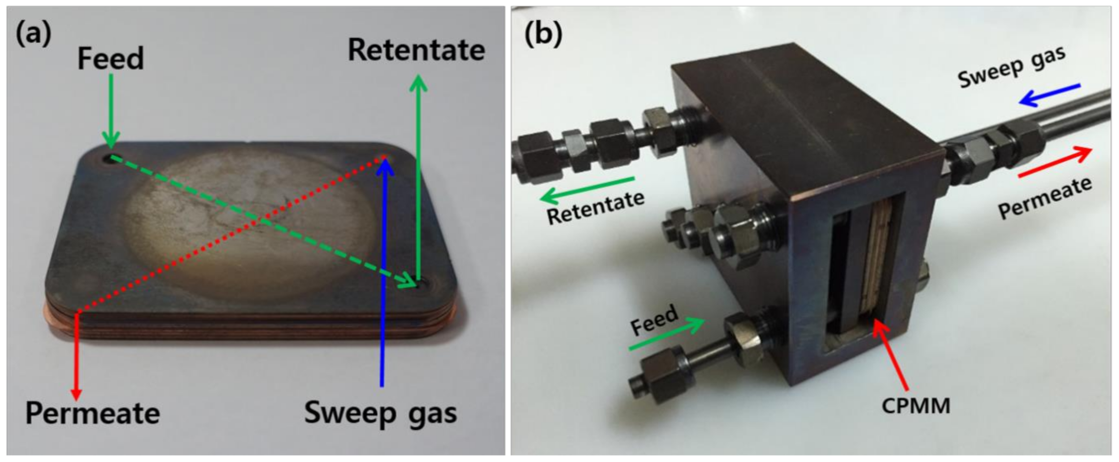
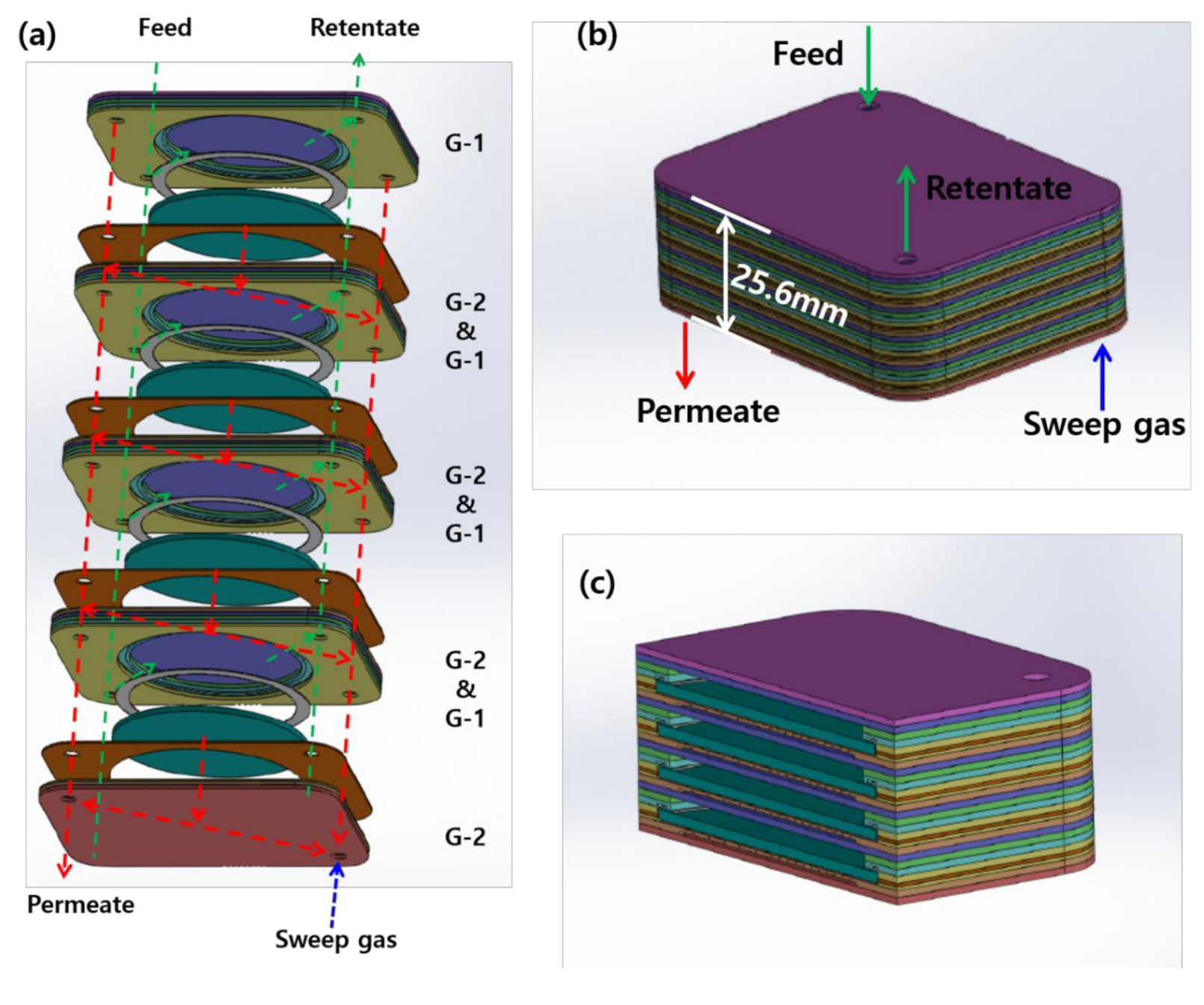
2.1. Design and Manufacture of the CPMM

The palladium based membranes were manufactured by our laboratory using the preparation procedures explained in a previous work [22,23]. Palladium was deposited on the prepared Porous nickel support (PNS) (49.3 mm) at 450 °C, 20 mTorr under Ar using a DC/RF magnetron sputter (Korea Vacuum Tech Co., Ltd., Daegu, Korea). Then, polishing and heat treatment were performed to produce a dense palladium membrane with improve selectivity. Figure S1 shows the cross-section SEM image of palladium membrane. The estimate thickness of palladium membrane layer was 2.7 μm. The constituents of the CPMM are shown in Figure 1. The module is composed of etched 316L SS plates (a, b), a palladium membrane (c), a Cu foil (d), and a Ag gasket (e). The 316L SS plates were chemically etched with various channels and holes. Figure 2 shows the components and gas path (retentate stream (G-1) and a permeate stream (G-2)) in the CPMM. The designed 316L SS plates consist of a cover plate (two sheets) of 1 mm thickness, a feed gas distribution plate (G-1-1), a plate for protection of the knife-edge (G-1-2), a knife-edge plate for membrane sealing (G-1-3), a membrane holder plate (G-1-4 and G-2-2), and permeate gas collection plates (G-2-1). Three-dimensional (3-D) porous channels were formed on the G-2-1 plate to sufficiently distribute the permeate gas through the Palladium membrane.
The G-1 and G-2 groups were modified using the following method to decrease the diffusion bonding temperature and to easily assemble components.
(1)
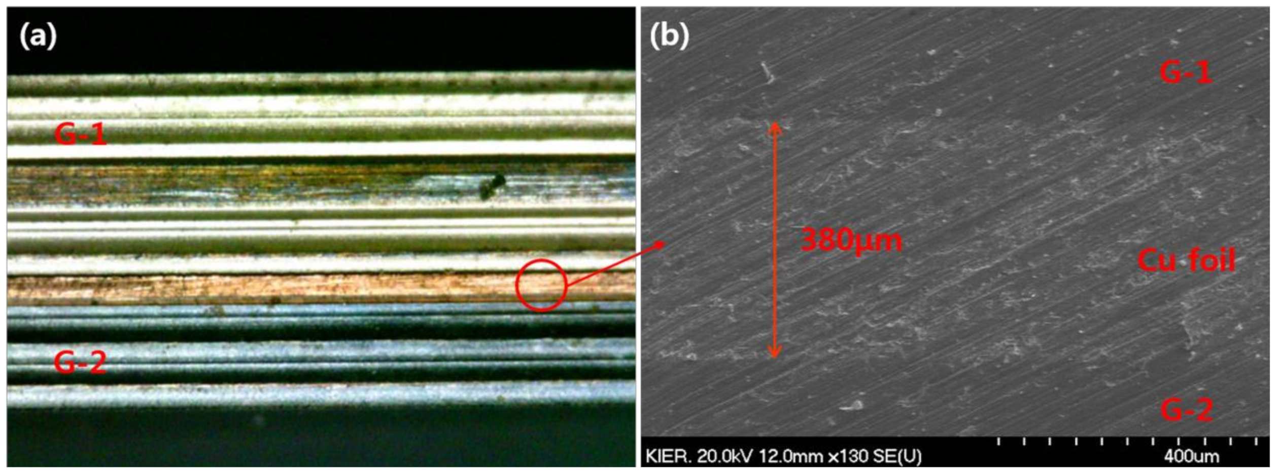
Each G-1 and G-2 part was diffusion bonded using hot-press (Samyang Ceratech Co., Ltd., Incheon, Korea) under high vacuum (3.0 × 10⁻⁶ Torr) and 900 °C
(2)
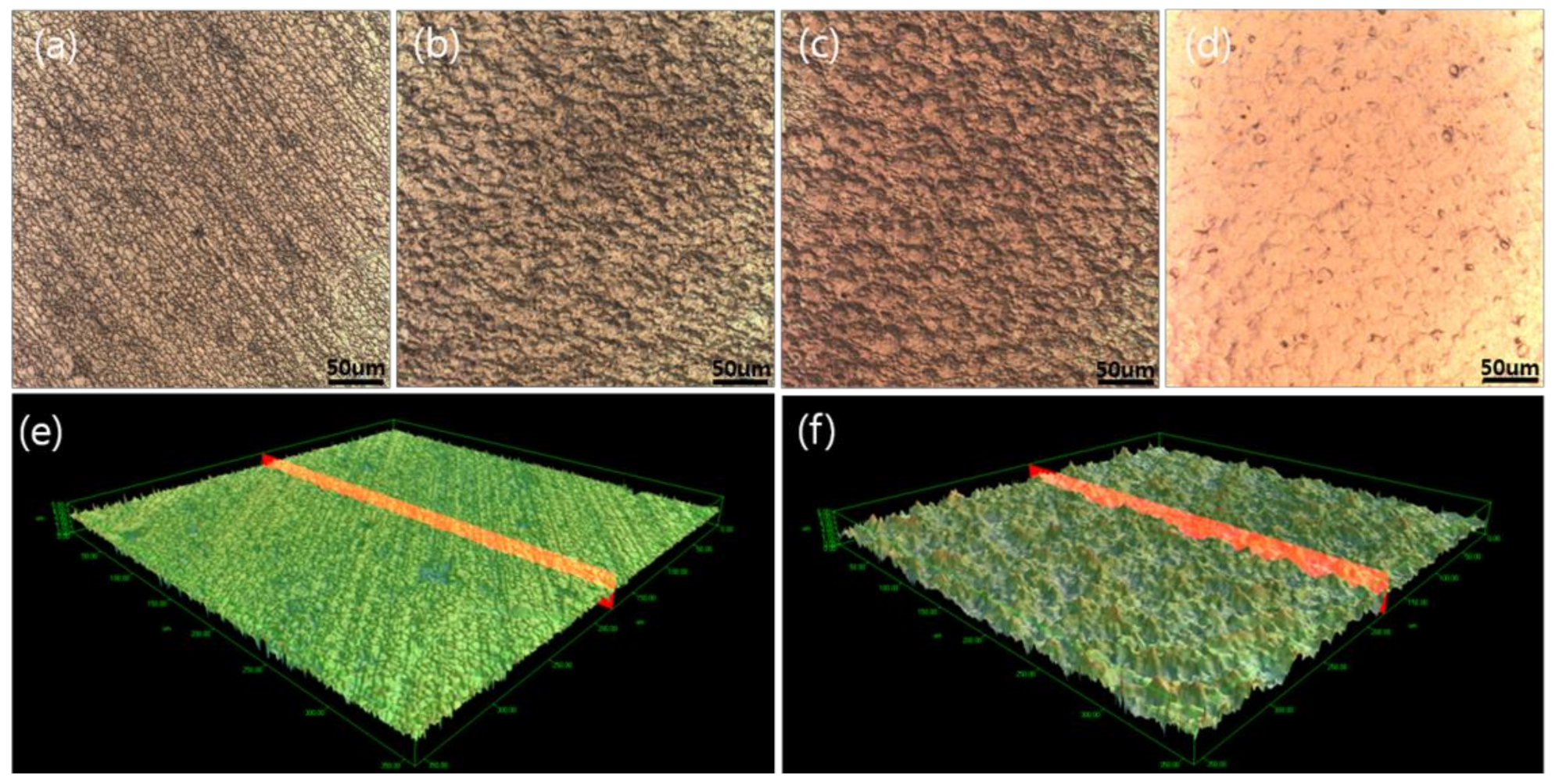
The surfaces of bonded G-1 and G-2 (G-1-4 in G-1 and G-2-2 in G-2) were peened using a peening machine (IEPCO PEENMATIC 550, Swiss Instruments Limited Co., Ltd., Mississauga, Canada) to increase the surface roughness using 316L SS powder by spraying method.
(3)
Ni and Cu were deposited over the peened surfaces of the G-1 and G-2 using the DC magnetron sputtering method.
(4)
G-1 and G-2 with Ni and Cu deposition were thermally treated under H2 condition at 700 °C for 2 h in the muffle furnace.
We analyzed the morphology, average surface roughness, and surface area of the modified surfaces using a color confocal microscope (H1200, Lasertec Co., Ltd., Hwa-seong, Korea). The CPMM was completed by diffusion bonding with modified G-1 and G-2, Cu foil (thickness 0.4 mm), Ag gasket (thickness 0.25 mm), and Palladium membrane. The diffusion bonding was performed at 450 °C for 5 h under high vacuum (3.0 × 10⁻⁶ Torr) and 20 Ton in the hot press. The leak test of the CPMM was performed at a pressure difference of 5 bar at room temperature.

2.2. Permeation Test Method of Hydrogen

The photograph of the diffusion bonded CPMM is shown in Figure 3a. Feed gas was introduced to the membrane through the G-1 group. Then, the permeated gas through the membrane was an exhaust-to-permeation stream through the G-2. The photograph of H2 permeation apparatus for the permeation experiment was shown in Figure 3b. The diffusion bonded CPMM was fixed and connected with a SS tube. The CPMM was heated in an electric furnace with a programmable temperature controller. The temperature of the furnace was controlled by a k-type thermocouple placed close to the membrane surface in the retentate stream. To prevent phase transition of the palladium, N2 was supplied up to 300 °C [24]. The permeation rates of H2 and N2 as a single gas were measured by a digital soap bubble flow meter (Gilibrator, SENSIDYNE Co., Ltd., Petersburg, FL, USA) at a pressure difference of 1 to 20 bar and 400 °C.
We performed the H2 separation tests using the H2/CO2 mixture gas at a pressure difference of 1–20 bar and a temperature of 400 °C with a feed gas flow rate range of 1.0–1.5 L min−1. We analyzed the H2 concentration of the permeate stream by Gas Chromatography. (G.C., 7890A, Agilent technology Co., Ltd., Santa Clara, CA, USA) equipped with a carboxen 1010 PLOT capillary column and thermal conductivity detector (TCD). Upon completion of the permeation testing, the membrane module was slowly cooled under N2. For cross-sectional analysis of the low-temperature diffusion bonded module, we used water-jet cutting and characterized the cut module by field emission scanning electron microscopy (FE-SEM, HITACHIS-4700).

3. Result and Discussion

3.1. Characterization of Membrane and CPMM

The average surface roughness (Ra) and surface area of the pretreated G-1 and G-2 groups were analyzed using a color confocal microscope, and the results are presented in Table 1. As shown in Table 1, The Ra values and areas of the surfaces modified by peening, Ni-Cu deposition, and thermal treatment were significantly different from those of the fresh, non-treated surfaces of G-1 and G-2. The Ra value of the peened surface was significantly higher (0.446 μm) than that of the fresh surface (0.167 μm). The increases in surface roughness and surface area of G-1 and G-2 were directly associated with effective diffusion bonding. This association means that the components can be effectively diffusion bonding at the low-temperatures. As shown in Figure 4, the surface morphologies of G-1 and G-2 obtained at different stages of surface modification were analyzed using a color confocal microscope. Figure 4a–d shows two-dimensional (2-D) surface images of the fresh and modified surfaces. After the peening process, the surface morphology showed higher surface roughness and surface area than those of the fresh surface morphology. Conversely, the surface morphology showed decreased surface roughness compared to the Ni-Cu-deposited surface by sputtering. Figure 4e,f shows the 3-D morphology of the untreated and peened surfaces. After the peening process, many pin-points were observed on the surface compared to the untreated surface of plate. The generated pin-points, designated with red color, were subjected locally to very high pressure during the diffusion-bonding step, resulting in easy assembly between the G-1 and G-2 groups at low-temperatures.
Figure 5 shows the cross-sectional image of the CPMM. As shown in Figure 5a, the height of assembled module was obtained 7.9 mm. Figure 5b shows the low-temperature bonded layers between the G-1 and Cu foil and the G-2 and Cu foil can be seen to be defect free.

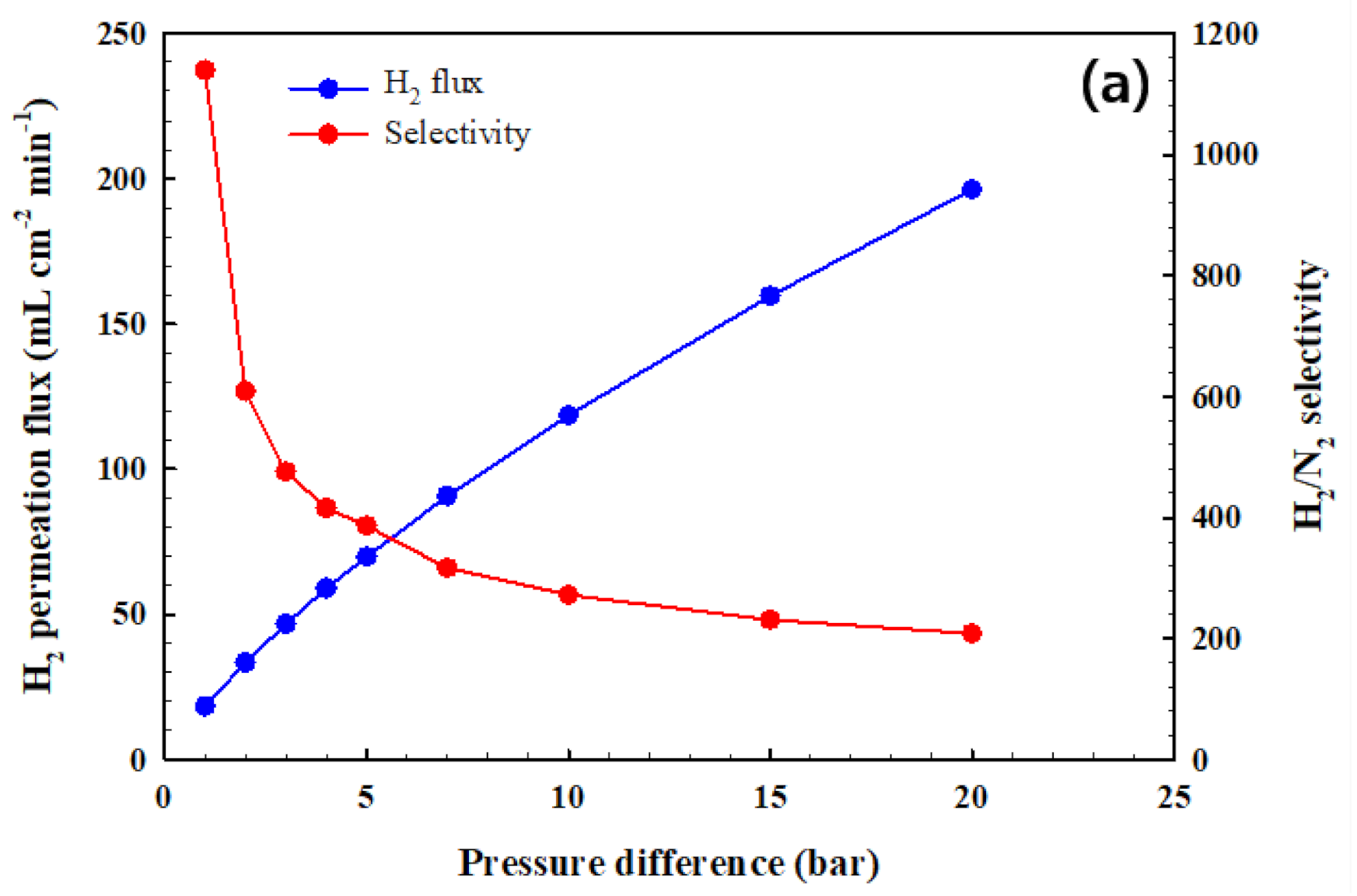
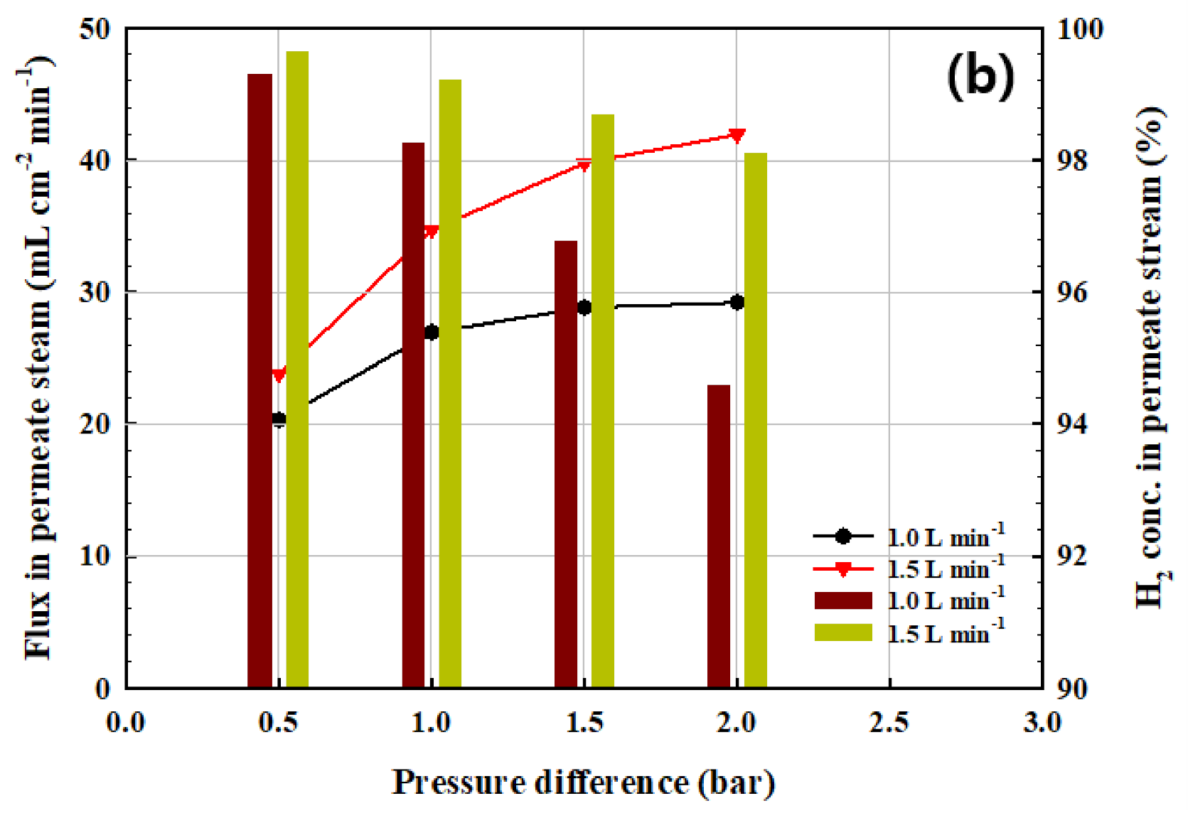
3.2. Hydrogen Permeation Test of the CPMM

The leak test of the CPMM installed with the palladium membrane was carried out using the N2 at room temperature. N2 of the permeate stream was not detected at a pressure difference of 1 bar and at room temperature. After confirming the leak-tightness of the CPMM, we carried out various performance tests. The performance of the membrane may be expressed in terms of a flux and selectivity as defined by Equations (1) and (2), respectively:
Flux = F/A
H2 Selectivity = H2 flow in permeate stream/N2 flow in permeate stream
where F represents the H2 flow through the membrane in the permeate stream and A is the effective area of the membrane (cm2).
We fabricated CPMM by diffusion bonding carried out a long-term stability test at a pressure difference of 1bar and 400 °C. As shown in Figure S2, the H2 permeation and H2 selectivity remained constant for ~365 h. Figure 6 shows the H2 permeation flux and selectivity using the pure gas and the flux and concentration of H2 in the permeation using the H2/CO2 mixture gas as a function of pressure difference at 400 °C. As shown Figure 6a, The H2 permeation flux significantly increased with pressure difference. The driving force for H2 separation is the pressure difference between the retentate and permeate. The flux of H2 through the CPMM ranged from 18.3 to 196.3 mL cm−2 min−1, depending on the pressure difference (1–20 bar). However, the H2/N2 selectivity significantly decreased from 1138 to 208 as the pressure difference was increased from 1 to 20 bar. The decrease in H2/N2 selectivity is considered to be due to the generated palladium fracture and defect of the membrane surface during the diffusion bonding of the CPMM. As shown in Figure 6b, the H2 separation test was performed using the 60% H2/40% CO2 mixture gas. The H2 separation capacity of the CPMM was examined with the H2/CO2 mixture gas flow rate of 1.0–1.5 L min−1 at 400 °C and a pressure difference ranging from 5 to 20 bar. The H2 flux increases with increasing pressure in the retentate stream. However, the H2 concentration decreases with increasing pressure due to H2/N2 selectivity, as shown in Figure 6a. The H2 concentration was >99% and H2 flux was 34.7 mL cm−2 min−1 in the permeate stream when the feed rate was 1.5 L min−1 and the pressure difference was 10 bar.
Figure 7 shows the drawing of multi stacked CPMM. The capacity of the multi stacked CPMM can be increased by scaling up the unit modules, as shown in Figure 7. The H2 flow of 2.1 L min−1 with H2 concentration of >99% will be produced by the multi-stacking membrane module with four membranes. Moreover, the module height is 25.6 mm and the module volume is 122.8 cm3. The module volume was 553.4 cm3 in the case of the frame-type membrane module with four membranes pre-studied in our laboratory [17]. The volume of multi stacked CPMM will be able to decrease by 77.8% at using the four membranes, compared with the frame-type membrane module.
Figure 8 shows the surface SEM images of the fresh and used palladium membranes in the CPMM. As shown Figure 8a, The surface of the fresh membrane was clear. However, despite diffusion bonding at a relatively low-temperature of 450 °C, some palladium fracture were partially formed on the surface of the palladium membrane, as seen in Figure 8b. This result indicates that the membrane morphology is affected and some sintering occurs on the top layer of the palladium membrane even when diffusion bonding is carried out at a low-temperature of 450 °C under high-vacuum conditions.

4. Conclusions

The CPMM was prepared and constructed for H2 separation. The G-1 and G-2 groups were prepared after the high-temperature diffusion bonding to reduce damage to the membrane. Next, the G-1 and G-2 groups was modified for low-temperature diffusion bonding of the module. The effective diffusion bonding area of the surface of the 316L SS plate was increased using peening, Ni-Cu deposition, and thermal treatment, resulting in perfect diffusion bonding of the membrane module at low-temperatures. The diffusion bonded module was obtained by height 7.9 mm, and volume 37.9 cm3. In addition, the volume of the diffusion bonded module than the pre-studied frame-type module were decreased by 81.4% [23]. Even though diffusion bonding was entirely performed at a low-temperature of 450 °C, a Palladium fracture was generated due to high-vacuum conditions on the membrane surface. The H2 permeation flux and the H2/N2 selectivity tests were conducted at a pressure difference of 1 bar, and a H2 flux of 18.3 mL cm−2 min−1 and H2/N2 selectivity of 1138 at 400 °C were observed in the CPMM. In the hydrogen separation test of H2/CO2 mixture gas, the H2 flux was 34.7 mL cm−2 min−1 and the H2 concentration was confirmed to be over 99.0%. However, the H2/N2 selectivity of the membrane decreased with increasing pressure difference. In the present study, we suggest that the CPMM can be used for compact H2 purifier. Further research is needed on the assembly methods to minimize membrane damage.

Supplementary Materials

The following are available online at https://www.mdpi.com/2077-0375/10/11/338/s1, Figure S1: Long-term stability test of CPMM; Temperature was 400℃; Pressure difference was 1 bar, Figure S2: Cross-sectional image of the prepared membrane; (a) FE-SEM, (b) FE-SEM/EDS.

Author Contributions

D.-K.O. (methodology, data curation, writing original draft preparation, formal analysis), K.-Y.L. (supervision), and J.-S.P. (conceptualization, writing, reviewing, and editing, project administration, funding acquisition). All authors have read and agreed to the published version of the manuscript.

Funding

This work was supported by the Research and Development Program of the Korea Institute of Energy Research (KIER) (Project No. B6-2451), Republic of Korea.

Acknowledgments

This work was supported by the Research and Development Program of the Korea Institute of Energy Research (KIER) (Project No. B6-2451), Republic of Korea.

Conflicts of Interest

The authors declare no conflict of interest.

References

  1. Xiao, Y.; Chung, T.S. Grafting thermally labile molecules on cross-linkable polyimide to design membrane materials for natural gas purification and CO2 capture. Energy Environ. Sci. 2011, 4, 201–208. [Google Scholar] [CrossRef]
  2. Authayanun, S.; Aunsup, P.; Patcharavorachot, Y.; Arpornwichanop, A. Theoretical analysis of a biogas-fed PEMFC system with different hydrogen purifications: Conventional and membrane-based water gas shift processes. Energy Convers. Manag. 2014, 86, 60–69. [Google Scholar] [CrossRef]
  3. Alenazey, F.; Alyousef, Y.; Almisned, O.; Almutairi, G.; Ghouse, M.; Montinaro, D.; Ghigliazza, F. Production of synthesis gas (H2 and CO) by high-temperature Co-electrolysis of H2O and CO2. Int. J. Hydrogen Energy 2015, 40, 10274–10280. [Google Scholar] [CrossRef]
  4. Rothenberger, K.S.; Cugini, A.V.; Howard, B.H.; Killmeyer, R.P.; Ciocco, M.V.; Morreale, B.D.; Enick, R.M.; Bustamante, F.; Mardilovich, I.P.; Ma, Y.H. High pressure hydrogen permeance of porous stainless steel coated with a thin palladium film via electroless plating. J. Membr. Sci. 2004, 244, 55–68. [Google Scholar] [CrossRef]
  5. Armaroli, N.; Balzani, V. The hydrogen issue. ChemSusChem 2011, 4, 21–36. [Google Scholar] [CrossRef]
  6. Shimura, K.; Yoshida, H. Heterogeneous photocatalytic hydrogen production from water and biomass derivatives. Energy Environ. Sci. 2011, 4, 2467–2481. [Google Scholar] [CrossRef]
  7. Holladay, J.D.; Hu, J.; King, D.L.; Wang, Y. An overview of hydrogen production technologies. Catal. Today. 2009, 139, 244–260. [Google Scholar] [CrossRef]
  8. Schell, J.; Casas, N.; Marx, D.; Mazzotti, M. Precombustion CO2 capture by pressure swing adsorption (PSA): Comparison of laboratory PSA experiments and simulations. Ind. Eng. Chem. Res. 2013, 52, 8311–8322. [Google Scholar] [CrossRef]
  9. You, Y.W.; Lee, D.G.; Yoon, K.Y.; Moon, D.K.; Kim, S.M.; Lee, C.H. H2 PSA purifier for CO removal from hydrogen mixtures. Int. J. Hydrogen Energy 2012, 37, 18175–18186. [Google Scholar] [CrossRef]
  10. Chen, W.H.; Hsu, P.C. Hydrogen permeation measurements of Pd and Pd-Cu membranes using dynamic pressure difference method. Int. J. Hydrogen Energy 2011, 36, 9355–9366. [Google Scholar] [CrossRef]
  11. Psara, N.; Van Sint Annaland, M.; Gallucci, F. Hydrogen safety risk assessment methodology applied to a fluidized bed membrane reactor for autothermal reforming of natural gas. Int. J. Hydrogen Energy 2015, 40, 10090–10102. [Google Scholar] [CrossRef]
  12. Tong, J.; Suda, H.; Haraya, K.; Matsumura, Y. A novel method for the preparation of thin dense Pd membrane on macroporous stainless steel tube filter. J. Membr. Sci. 2005, 260, 10–18. [Google Scholar] [CrossRef]
  13. Mardilovich, I.P.; Castro-Dominguez, B.; Kazantzis, N.K.; Wu, T.; Ma, Y.H. A comprehensive performance assessment study of pilot-scale Pd and Pd/alloy membranes under extended coal-derived syngas atmosphere testing. Int. J. Hydrogen Energy 2015, 40, 6107–6117. [Google Scholar] [CrossRef] [Green Version]
  14. Ryi, S.K.; Park, J.S.; Kim, S.H.; Cho, S.H.; Kim, D.W. The effect of support resistance on the hydrogen permeation behavior in Pd-Cu-Ni ternary alloy membrane deposited on a porous nickel support. J. Membr. Sci. 2006, 280, 883–888. [Google Scholar] [CrossRef]
  15. Kurokawa, H.; Yakabe, H.; Yasuda, I.; Peters, T.; Bredesen, R. Inhibition effect of CO on hydrogen permeability of Pd-Ag membrane applied in a microchannel module configuration. Int. J. Hydrogen Energy 2014, 39, 17201–17209. [Google Scholar] [CrossRef]
  16. Xie, D.; Yu, J.; Wang, F.; Zhang, N.; Wang, W.; Yu, H.; Peng, F.; Park, A.H.A. Hydrogen permeability of Pd-Ag membrane modules with porous stainless steel substrates. Int. J. Hydrogen Energy 2011, 36, 1014–1026. [Google Scholar] [CrossRef]
  17. Ryi, S.K.; Park, J.S.; Hwang, K.R.; Lee, C.B.; Lee, S.W. The property of hydrogen separation from CO2 mixture using Pd-based membranes for carbon capture and storage (CCS). Int. J. Hydrogen Energy 2013, 38, 7605–7611. [Google Scholar] [CrossRef]
  18. Borgognoni, F.; Tosti, S. Multi-tube Pd-Ag membrane module for pure hydrogen production: Comparison of methane steam and oxidative reforming. Int. J. Hydrogen Energy 2013, 38, 8276–8284. [Google Scholar] [CrossRef]
  19. Maneerung, T.; Hidajat, K.; Kawi, S. Ultra-thin (<1 μm) internally-coated Pd-Ag alloy hollow fiber membrane with superior thermal stability and durability for high temperature H2 separation. J. Membr. Sci. 2014, 452, 127–142. [Google Scholar] [CrossRef]
  20. Ryi, S.K.; Park, J.S.; Choi, S.H.; Cho, S.H.; Kim, S.H. Novel micro fuel processor for PEMFCs with heat generation by catalytic combustion. Chem. Eng. J. 2005, 113, 47–53. [Google Scholar] [CrossRef]
  21. Li, S.X.; Xuan, F.Z.; Tu, S.T.; Yu, S.R. Microstructure evolution and interfacial failure mechanism in 316LSS diffusion-bonded joints. J. Mater. Sci. Eng. A. 2008, 491, 488–491. [Google Scholar] [CrossRef]
  22. Hwang, K.R.; Ryi, S.K.; Lee, C.B.; Lee, S.W.; Park, J.S. Simplified, plate-type Pd membrane module for hydrogen purification. Int. J. Hydrogen Energy 2011, 36, 10136–10140. [Google Scholar] [CrossRef]
  23. Lee, S.W.; Oh, D.K.; Park, J.W.; Lee, C.B.; Lee, D.W.; Park, J.S.; Kim, S.H.; Hwang, K.R. Effect of a Pt-ZrO2 protection layer on the performance and morphology of Pd-Au alloy membrane during H2S exposure. J. Alloys Compd. 2015, 641, 210–215. [Google Scholar] [CrossRef]
  24. Hwang, K.R.; Lee, S.W.; Ryi, S.K.; Kim, D.K.; Kim, T.H.; Park, J.S. Water-gas shift reaction in a plate-type Pd-membrane reactor over a nickel metal catalyst. Fuel Process. Technol. 2013, 106, 133–140. [Google Scholar] [CrossRef]
Figure 1. Constituent photographs of compact palladium membrane module (CPMM); etched 316L stainless steel (SS) plates of (a) feed stream and (b) permeate stream, (c) disc-shaped Pd-based membrane, (d) Cu foil, (e) Ag gasket.
Membranes 10 00338 g001
Figure 2. The components and gas path in the CPMM; Green line: Feed stream gas path, Red line: Permeate stream gas path.
Membranes 10 00338 g002
Figure 3. The photograph of (a) diffusion bonded CPMM and (b) the assembled H2 permeation apparatus.
Membranes 10 00338 g003
Figure 4. The surface image of modified 316L SS plate by color confocal microscope; 2-D image: (a) Fresh, (b) peening, (c) Ni-Cu deposition, (d) thermal treatment; 3-D image: (e) Fresh and (f) peening.
Membranes 10 00338 g004
Figure 5. The cross-sectional image of diffusion bonded CPMM; (a) photograph, (b) SEM image of diffusion bonded layer.
Membranes 10 00338 g005
Figure 6. The performance test of CPMM as a function of pressure difference at the temperature of 400 °C; (a) the hydrogen permeation flux and H2/N2 selectivity, (b) the flux and H2 concentration of permeation gas using the H2/CO2 mixture gas; vertical bar plot: H2 concentration, line plot: H2 flux.
Membranes 10 00338 g006aMembranes 10 00338 g006b
Figure 7. The schematic drawing of multi stacked CPMM; (a) layout of the gas path in the CPMM, (b) multi stacked CPMM, (c) cross-section of multi stacked CPMM.
Membranes 10 00338 g007
Figure 8. The surface SEM image of Palladium membrane; (a) fresh membrane, (b) membrane after the diffusion bonding and permeation test.
Membranes 10 00338 g008
Table 1. The surface properties of modified commissure by color confocal microscope.
ProcessRa (µm)Surface Area (mm2)
Fresh0.1670.128
Peening0.4460.132
Ni-Cu deposition0.5820.133
Thermal treatment0.5200.132
Publisher’s Note: MDPI stays neutral with regard to jurisdictional claims in published maps and institutional affiliations.

