Article

Comparative Study of the Trueness of the Inner Surface of Crowns Fabricated from Three Types of Lithium Disilicate Blocks

1
Department of Dental Science, Graduate School, Kyungpook National University, Daegu 41940, Korea
2
Advanced Dental Device Development Institute, Kyungpook National University, Daegu 41940, Korea
3
Department of Prosthodontics, Hamdan Bin Mohammed College of Dental Medicine, Mohammed Bin Rashid University, Dubai 505055, UAE
4
Department of Prosthodontics, School of Dentistry, Kyungpook National University, Daegu 41940, Korea
*
Author to whom correspondence should be addressed.
Appl. Sci. 2019, 9(9), 1798; https://doi.org/10.3390/app9091798
Submission received: 21 March 2019 / Revised: 22 April 2019 / Accepted: 26 April 2019 / Published: 29 April 2019

Abstract

:
This study set out to compare the three-dimensional (3D) trueness of crowns produced from three types of lithium disilicate blocks. The working model was digitized, and single crowns (maxillary left second molar) were designed using computer-aided design (CAD) software. To produce a crown design model (CDM), a crown design file was extracted from the CAD software. In addition, using the CDM file and a milling machine (N = 20), three types of lithium disilicate blocks (e.max CAD, HASS Rosetta, and VITA Suprinity) were processed. To produce a crown scan model (CSM), the inner surface of each fabricated crown was digitized using a touch-probe scanner. In addition, using 3D inspection software, the CDM was partitioned (into marginal, axis, angular, and occlusal regions), the CDM and CSM were overlapped, and a 3D analysis was conducted. A Kruskal–Wallis test (α = 0.05) was conducted with all-segmented teeth with the root mean square (RMS), and they were analyzed using the Mann–Whitney U-test and the Bonferroni correction method as a post hoc test. There was a significant difference in the trueness of the crowns according to the type of lithium disilicate block (p < 0.001). The overall RMS value was at a maximum for e.max (42.9 ± 4.4 µm), followed by HASS (30.1 ± 9.0 µm) and then VITA (27.3 ± 7.9 µm). However, there was no significant difference between HASS and VITA (p = 0.541). There were significant differences in all regions inside the crown (p < 0.001). There was a significantly high trueness in the angular region inside the crown (p < 0.001). A correction could thus be applied in the CAD process, considering the differences in the trueness by the type of lithium disilicate block. In addition, to attain a crown with an excellent fit, it is necessary to provide a larger setting space for the angular region during the CAD process.

1. Introduction

The introduction of dental computer-aided design and computer-aided manufacturing (CAD-CAM) technology has led to a decrease in practitioner errors as well as material failures [1,2]. In addition, production efficiency is greatly superior with CAD-CAM, compared to other existing methods [3]. The CAD-CAM process produces prostheses through scanning, CAD, and then CAM processes.
The development of intraoral scanners and their combination with dental CAD-CAM systems has made it possible for all prosthesis production to be performed chairside [4,5]. Since a chairside CAD-CAM process does not need a working model and involves a shorter prosthesis processing and postprocessing time, a prosthesis can be produced and provided to a patient more rapidly. In addition, since zirconia requires time for postprocessing sintering [6], lithium disilicate is more commonly used for chairside production [7]. In addition, previous studies have shown that lithium disilicate crowns have a higher survival rate than feldspathic porcelain and alumina-oxide crowns do [8]. To further improve chairside CAD-CAM systems (by enhancing their accuracy and production speed), the development of intraoral scanners, CAM equipment, and materials is ongoing [9].
CAM processes are classified as either subtractive or additive manufacturing [10], but milling (a subtractive process) is actually used as a CAM process. In fact, milling is the most commonly used manufacturing process. For CAM, a five-axis milling unit can produce prostheses more accurately than a four-axis machine can [11,12,13]. With a five-axis milling machine, it is possible to mill pointed angles more accurately, given that a wider range of milling with a greater number of axes relative to the four-axis can be used [11,14]. With a five-axis milling machine, the contact point between the tool and the prosthesis to be milled can be controlled, thus realizing better control of the milling conditions. However, somewhat more time is required to complete machining when using a five-axis milling unit [11]. Accordingly, for chairside CAD-CAM, the use of a four-axis milling unit is preferred to keep the chairside time within a clinically acceptable range. Several studies have evaluated the impact of the use of a chairside four-axis milling unit on the inner surface of the prosthesis [11,12]. To the best of our knowledge, however, there have been no studies that have evaluated trueness according to region.
Already, as a result of many preceding studies, chairside CAD-CAM production of prostheses is clinically practical [2,15,16,17,18,19,20]. Neves [15] compared the fit of prostheses produced by a chairside CAD-CAM process to those produced by a laboratory (CAD-CAM) process. The prosthesis produced by the chairside process had a superior fit. Dolev [16] compared the fit of prostheses produced by a chairside (CAD-CAM) process to those produced by a laboratory (hot-press) process using a lithium disilicate material. The crown produced by the chairside process had a clinically acceptable fit. In a three-year clinical evaluation, Lu [17] predicted the growth of chairside CAD-CAM as an alternative to prosthetic therapy, given a crown survival rate of 97.0%.
Three-dimensional (3D) evaluation is often applied to determine whether mass-produced products have been accurately produced by manufacturing processes [21,22,23]. This can save time compared to visual examinations, [21] and an accurate analysis can be conducted with the development of a scanner [9]. Visual examinations require more time because human errors can occur and given that the evaluation is done by hand. In addition, due to advances in scanning technology, very precise scanning (<10 μm) can be obtained, and accurate analysis is possible. Likewise, given the take-up of CAD-CAM techniques in dentistry, three-dimensional data have been evaluated in numerous studies [5,24,25,26,27,28]. The distance from a certain reference point or a form has been measured [25,29,30], and 3D analysis has been conducted by overlapping a CAD reference model onto a CAD test model [5,24,25,26,28]. This 3D analysis relies on an alignment process whereby the CRM is overlapped using software. In general, the overlap is investigated through best fit alignment [31,32].
It is important to determine whether the prosthesis fit is within a clinically allowable range. More important than this, however, is the trueness of the manufactured prosthesis. “Trueness” is the similarity between the prosthesis designed first in CAD (the CAD reference model) and the ultimately manufactured prosthesis (CAD test model) [28,33,34,35]. A trueness evaluation is important because an inaccurate inner surface on the prosthesis is one of several factors (dental preparation, preparation’s scan) that affect the marginal and internal fit. An inaccurate inner surface on the inner prosthesis requires the dentist to postprocess the crown with a dental handpiece. This operation can increase the risk of fatigue crack initiation, leading to a shorter crown service life. Furthermore, a prosthesis with an excellent degree of trueness can reduce chairside time [13,36]. Many previous studies have evaluated the trueness of the prosthesis [13,35,36,37,38]. The benefit of evaluating the trueness according to the region is to assess which region exhibits poor trueness, which can be used as reference data for the marginal and internal fit of the prosthesis. However, there have been no studies that have evaluated the trueness of the inner surface of the crowns and how that varies with the type of lithium disilicate block.
In the present study, therefore, we began with a 3D comparison of the trueness of crowns produced using three types of lithium disilicate block. Then, we undertook a 3D comparison of the trueness according to the position of the crown. To this end, a null hypothesis was set as follows: There is no difference in the trueness of the crowns produced, regardless of the type of lithium disilicate block used, and there is no difference in the trueness according to the positions of the inner surfaces of the crowns.

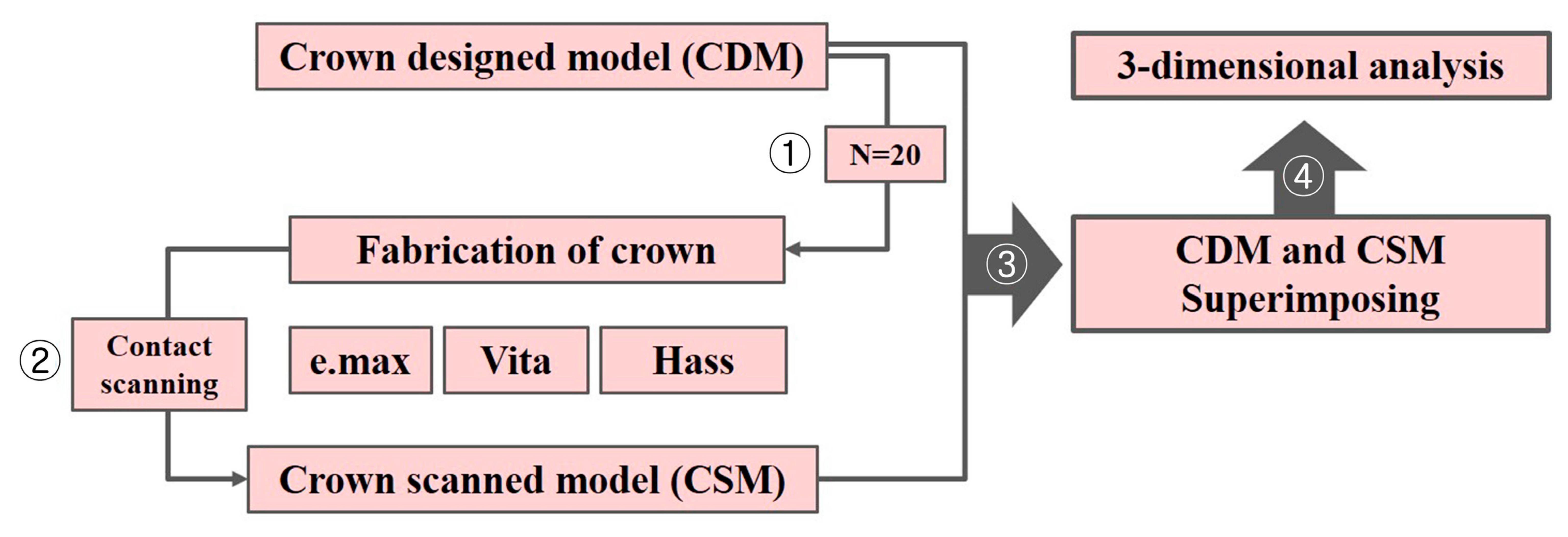
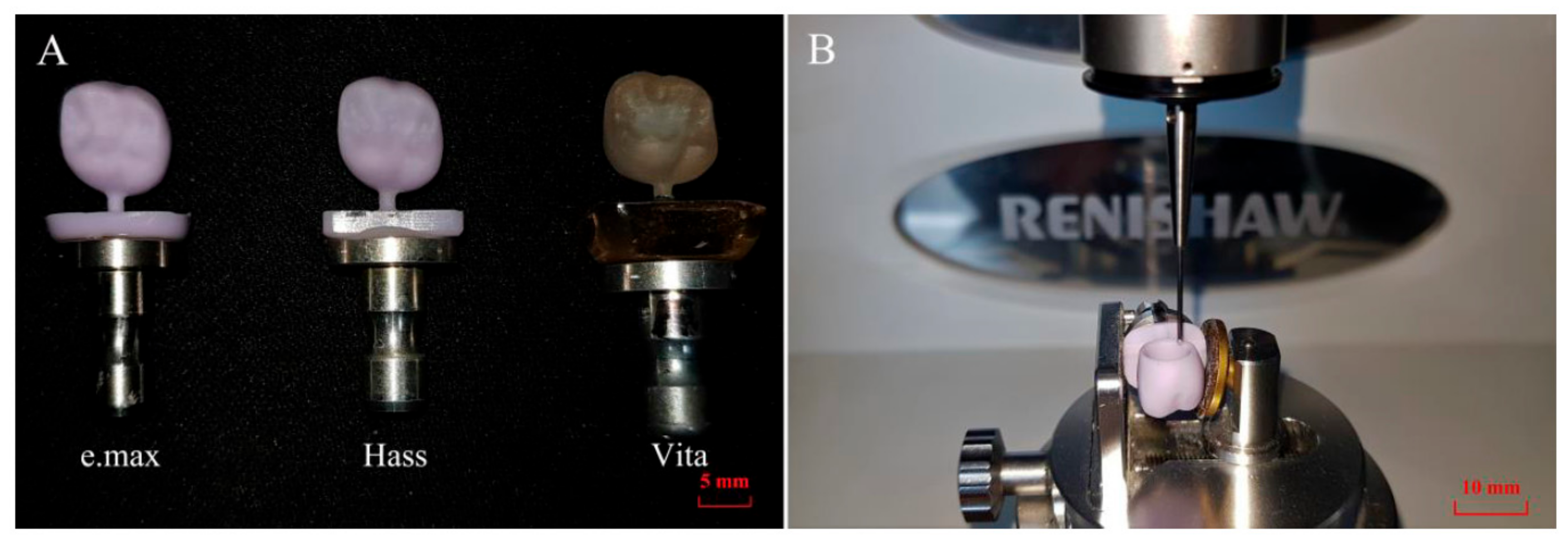
2. Materials and Methods
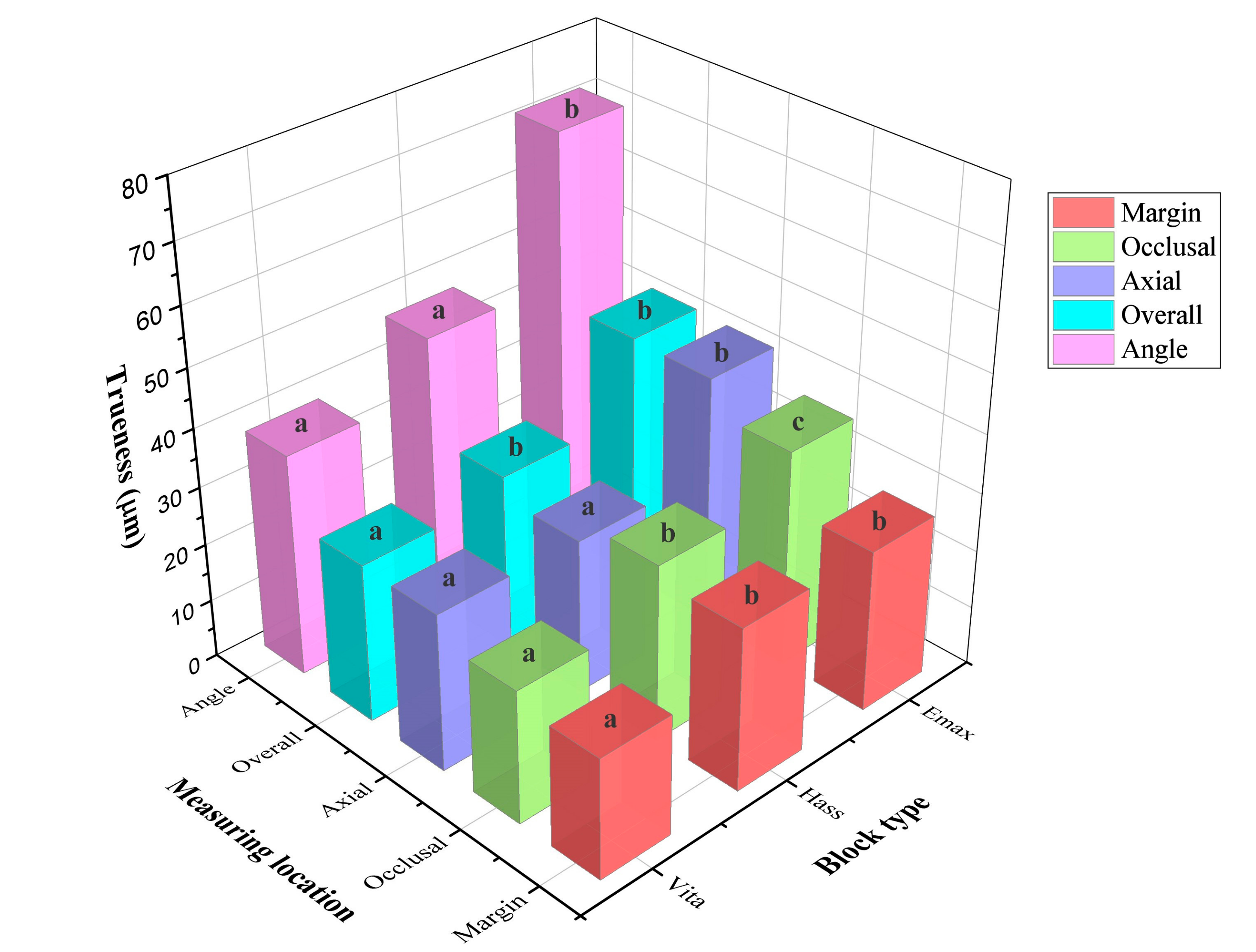
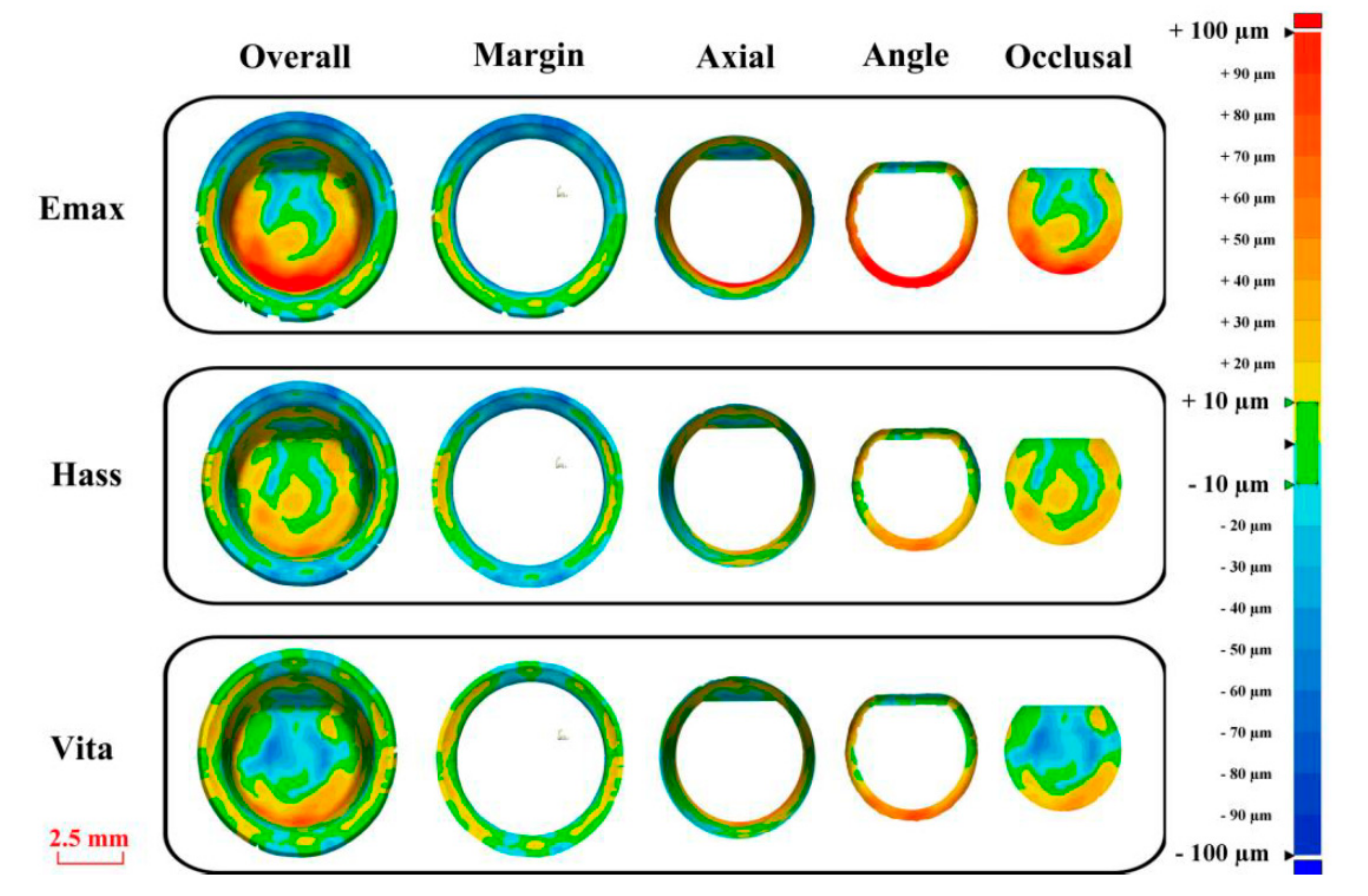
The present study involved the design of crowns using CAD software (crown-designed model (CDM)), the production of crowns using milling machines, the digitization of the inner surface of the crowns using a touch-probe scanner to obtain a crown scanned model (CSM), and overlapping of the CDM and CSM using testing software for analysis. A 3D analysis was also conducted (Figure 1).
To determine the sample size, a pilot experiment was conducted five times. A power analysis (G*Power v3.1.9.4, Heinrich-Heine-Universität, Dusseldorf, Germany) revealed that an appropriate sample size would be 20 (actual power = 98.93%; power = 98.9%; α = 0.05).
A single crown was designed by dental CAD software (EZIS VR, Digital Dentistry Solution, Seoul, Korea). The default values recommended by the manufacturer were set for the inner and outer surfaces of the crown. In addition, the designed virtual crown was extracted as a stereolithography (STL) file (CDM) to enable its use as the base data for the trueness evaluation.
To produce the STL file for the designed crown, it was moved to a milling unit (EZIS HM; Digital Dentistry Solution, Seoul, Korea). The EZIS HM is a chairside four-axis milling unit. A crown milling path based on the STL file was set in the CAM software (EZIS VR; Digital Dentistry Solution, Seoul, Korea). According to the manufacturer, it offers a processing accuracy of ±10 µm and a maximum spindle speed of 63,000 rpm and can produce a crown at a rate of 15 min/unit. In addition, for the production of a more precise prosthesis, the manufacturer calibrated the milling unit. In addition, three types of lithium disilicate blocks (e.max CAD, HASS Rosetta, and VITA Suprinity) were used: The data for these three types of lithium disilicate blocks are listed in Table 1. The lithium disilicate block was mounted in the milling unit and processed (Figure 2A). A pilot test revealed that there was no difference in the trueness of five crowns processed using one burr instrument (Step Bur 12 and Cylinder Pointed Bur 12s, Dentsply Sirona, York, PA, USA) (P = 0.172). For the processing, the burr was replaced five times.
Any residue was removed from the produced crown by washing it in distilled water for 5 min using an ultrasonic cleaner. After drying, it was mounted in a jig, and its inner surface was scanned using a touch–probe scanner (DS10, Renishaw plc, Gloucestershire, UK) without a crystallization firing cycle (Figure 2B). The touch–probe scanner uses a probe, which gently touches the surface and is capable of rising and falling through 200 µm. The inner surface of the crown milled using the 1.0 mm milling burr was precisely scanned using a probe with a diameter of 0.5 mm. The touch probe was used to scan from the inner end of the crown to the end of the crown margin. The coordinates of about 20,000 points on the inner surface of the crown were recorded by the touch probe. Since the use of this method did not incur any errors caused by the optical characteristics of the object, it was ideal for scanning the inner surface of a lithium disilicate crown. In addition, the trueness could be analyzed precisely because of the excellent repeatability/reproducibility that was possible with this instrument [39]. To ensure accuracy, the touch-probe scanner was calibrated prior to each scan. All of the scanning processes conducted as part of this study were conducted at an ambient temperature of 23 ± 2 °C in accordance with international organization of standardization (ISO)-12836. Since errors may occur depending on the operator [27,40], a single skilled operator (K.S.) performed all of the scans and analyses. In addition, the scanned virtual crown was extracted as an STL file to enable its use as test data in the trueness evaluation (CSM).
The 3D analysis program used in this study was Geomagic Company’s 3D inspection software (Geomagic control X v2018.0.0, 3D Systems Inc, Rock Hill, SC, USA), as recommended by ISO-12836 [27]. Since errors may occur depending on the operator [27,40], a single skilled operator (K.S.) performed all of the analyses. A CDM file was retrieved with the 3D inspection software, which was set to perform a 3D comparison of the inner surface of the crown. The inner surface of the crown was divided into four parts (marginal, axis, angular, and occlusal regions). The trueness of the inner surface of the crown may affect the marginal and internal fit, and many previous studies have evaluated the marginal and internal fit according to the region [2,13,14,15,16,17,18]. Therefore, the inner surface of the crown was divided into four parts to evaluate the trueness. The region up to 0.5 mm from the prosthesis margin was defined as the marginal region, the region starting at the end of the marginal region through the axis to the point where the curve starts was the axis region, the region starting from the end of the axis region through the line angle to the point where the curve ends was the angular region, and the remaining region starting from the angular region was the occlusal region.
After preparing a CDM file, a CSM file was retrieved, and the initial alignment was conducted with the best fit alignment. The inner region of the partitioned crown was appointed, and it was overlapped with the best fit alignment only in the point cloud of the appointed part. The sampling ratio was set to 100%.
The dimensional difference between the CDM file and the CSM file was calculated for all data points of the partitioned inner region. The differences between all of the data points of the CDM and CSM were calculated from the closest data points to each other in all directions. At this time, the data points were calculated with the root mean square (RMS) value using the following formula:
R M S = 1 n · i = 1 n X 1 , i X 2 , i 2
For all data points, X 1 , i was the position of measurement point i in the reference scan data, and X 2 , i was the position of measurement point i in the evaluation scan data. In addition, n refers to the total number of data points measured in each analysis.
The RMS value indicates the degree of deviation of the scan data. A low RMS value indicates a good three-dimensional agreement of the overlapped data [27].
The CAM process aims to reproduce a modeled design and produce an accurate product. The tool target position may not be reached or exceeded, however, due to various factors affecting the cutting rate (e.g., the hardness of the material, the performance of the milling unit). Therefore, the 3D comparison is shown as a color difference map, with a range of ±100 µm (20 color segments) and an allowable tolerance range (green) of ±10 µm assigned. The red zone (10~100 µm) shows that the CSM data are located above the CDM data, implying that the milling failed to reach the target position. In addition, the blue zone (−10 to −100 µm) shows that the CSM data are located below the CDM data, implying that the milling exceeded the target position. The green zone (±10 µm) corresponds to the areas that were machined very accurately.
All of the data were analyzed using SPSS statistical software (IBM SPSS Statistics v23.0, IBM Corp, USA). First, through an application of the Shapiro–Wilk test, the normal distribution of the data was investigated. Since they did not form a normal distribution, the presence of any difference between the groups was checked by performing a Kruskal–Wallis test (α = 0.05). In addition, as a post hoc test, the difference between the groups was analyzed using the Mann–Whitney U-test and the Bonferroni correction method.

3. Results

There was a significant difference in the trueness of the inner surface of the crown according to the type of lithium disilicate block (p < 0.001; Figure 3; Table 2). There was no significant difference between e.max (27.7 ± 2.9 µm) and HASS (28.0 ± 3.4 µm) in the marginal region (p = 1.0), while the trueness was at a minimum for VITA (20.7 ± 6.6 µm) (p < 0.001). In addition, the values for the axis, angular, and occlusal regions were the highest for e.max, and there was no significant difference between HASS and VITA (p > 0.05). The overall RMS value was at a maximum (42.9 ± 4.4 µm) for e.max, followed by HASS (30.1 ± 9.0 µm) and then VITA (27.3 ± 7.9 µm). However, there was no significant difference between HASS and VITA (p = 0.541).
There was a significant difference between all of the regions for the inner surface of the crown (p < 0.001; Table 2). The angular region on the inner surface of the crown exhibited a significantly higher trueness (p < 0.005). There was no significant difference in the marginal, angular, or occlusal regions, except for in the e.max group (p > 0.05).
Figure 4 and Figure 5 show the color difference map of the 3D analysis. In the angular region, the red zone is predominant, meaning that the milling failed to reach the target position. In the marginal region, the green color is most common, indicating that the milling was performed accurately. In the axis and occlusal regions, several color zones appear to equal degrees. The green zone appears the least with e.max. Furthermore, in the angular and occlusal regions, the range of the red zone is greatest.

4. Discussion

According to the findings of recent studies, the development of chairside CAD-CAM has enabled the creation of accurately fixed prostheses in a short time. However, the results of the present study revealed that the trueness of the produced crowns might vary depending on the type of lithium disilicate block used. In a clinic, a crown should be designed while considering the difference in trueness that arises as a result of the type of lithium disilicate block used. For example, when using CAD software to design a crown, a higher space value should be given to e.max than to HASS and VITA, or the inner surface should be further adjusted after production. If this compensation is not applied, it may take much time for the final fitting and adjustment of the prosthesis in the oral cavity.
Based on the results of the present study, we can conclude that the trueness may differ depending on the position of the inner surface of the crown. In particular, the red zones tended to dominate (10~100 µm) in the angular region. This implies that the milling failed to reach the target position. The reason for this has been identified in previous studies. Kim [28] noted that the number of mill burrs affects the accuracy, with the trueness being better when three burrs were used, relative to when two burrs were used. The use of three burrs produced a better trueness than when only two burrs were used because the use of three burrs led to a greater range of burr diameters. A smaller-diameter burr could be used to more precisely mill angular regions. Kirsch [13] found that the trueness was lower with a five-axis milling machine than with a four-axis machine. This is because the stiffness of a milling machine decreases as the number of axes increases. In regions with, for example, line angles, processing using a four-axis milling machine is difficult due to the entry angle and the size of the burr. In the present study, a four-axis milling machine of the type that is often used chairside was used. We judged that it would be possible to compare it to a five-axis milling unit if we were to refer to the results of previous studies.
Since different types of lithium disilicate blocks vary in terms of their cutting rates, we could assume that the trueness would differ depending on the type of lithium disilicate block used. Since our study controlled for various variables (replacement of the milling burr, the use of a milling machine with high accuracy (±10 µm), the use of a touch–probe scanning process in which the ceramic material did not scatter the light, and a sufficient sample size with an actual power of 98.93%), this assumption was reliable. If the hardness of the material themselves is low, the cutting rate is greater, and hardness varies depending on the product. The milling conditions (precision, spindle speed, number of axes) depend on the type of milling unit. Further studies should be conducted to analyze the differences between the biomaterials tested. According to Song [41], the feed rate and depth of cut may differ depending on the type of block, with lithium disilicate ceramic being the most difficult of the ceramic materials to process. However, for this hypothesis to be reliable, we should undertake a subsequent study that measures the surface hardness of the lithium disilicate block and analyzes its correlation with the trueness.
The inner trueness of a lithium disilicate crown was evaluated without a crystallization firing cycle. The crystallization firing cycle causes some shrinkage [42] and can affect the trueness. The method described herein did not involve a crystallization firing cycle. This was done to exclude any variables that could occur in the firing cycle. However, further studies are needed to evaluate the trueness after the crystallization firing cycle to better approximate actual clinical practice.
Reference data are necessary to determine the trueness. The method whereby this reference data are obtained is very important. Previous studies have analyzed data, calculating the distance of the coordinates of the reference data obtained with a touch-probe scanner [43]. In addition, Park [27] measured the trueness, obtaining three-dimensional reference data with a precision industrial scanner. The touch–probe scanner was more accurate and more stable than an optical scanner and was more efficient at representing the abutment tooth margin than a laser scanner [44]. In addition, Dimitrova [39] measured repeatability/reproducibility, taking pictures of the abutment tooth with an optical scanner and measurements with a touch–probe scanner, with the results obtained with the touch–probe scanner exhibiting excellent repeatability/reproducibility (optical scanner: 8.2 µm; touch–probe scanner: 6.9 µm).
However, unlike in some previous studies [28,45], the trueness of the outer surface of the crown was not evaluated in the present study. We were unable to do so because the narrow deep regions and the regions with an undercut could not be scanned using a touch–probe scanner. In addition, the parts connected to the outer surface when the crown was separated from the block may have, for additional reasons, affected the trueness. However, further study should be undertaken to analyze the trueness of the outer surface of the crown.

5. Conclusions

Based on the findings of this in vitro study, the following conclusions were drawn:
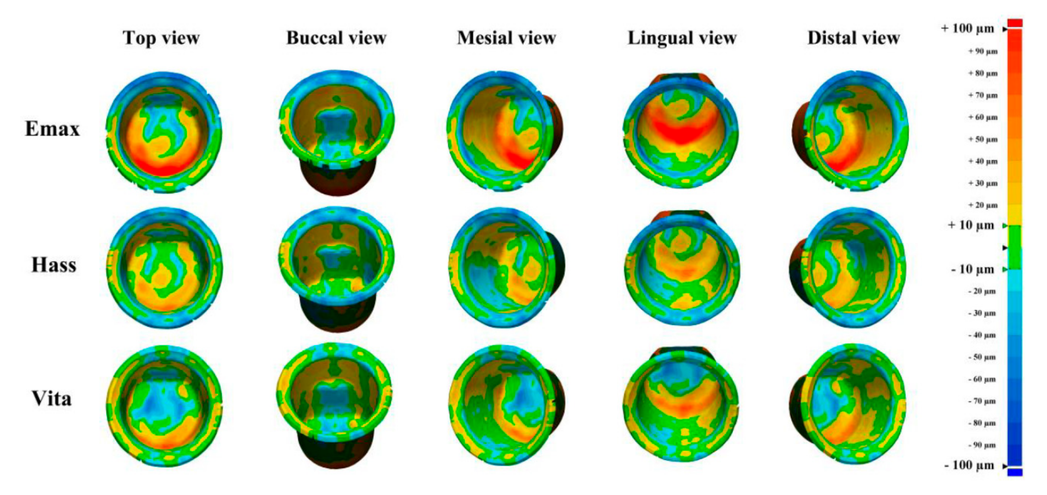
  • The trueness of the fabricated crown depended on the type of lithium disilicate block used;
  • Therefore, to ensure an excellent marginal and internal fit, consideration should be given to the marginal and internal setting space in the CAD process by referring to the variation in the trueness of the fabricated crown with the type of lithium disilicate block;
  • The inner surface of the crown exhibited a different degree of trueness depending on the milling;
  • The angular regions of the crown exhibited the greatest degree of error, so compensation in the CAD process is necessary.

Author Contributions

Conceptualization, K.S.; methodology, K.L.; validation, K.L.; formal analysis, B.Y.; investigation, K.S.; data curation, B.Y.; writing—original draft, K.S.; visualization, K.S.; revising the paper, T.Y.; supervision, K.L.; project administration, K.L.

Funding

This research was supported by the Ministry of Trade, Industry, & Energy (MOTIE, Korea) under the Industrial Technology Innovation Program (No. 10062635) and the Institute for Information & Communications Technology Promotion (IITP) by a grant funded by the Korea government (MSIP) (B0101-19-1081).

Acknowledgments

The authors thank the researchers of the Advanced Dental Device Development Institute, Kyungpook National University, for their time and contributions to the study.

Conflicts of Interest

The authors declare no conflicts of interest. The funders had no role in the design of the study; in the collection, analyses, or interpretation of the data; in the writing of the manuscript; or in the decision to publish the results.

References

  1. Christensen, G.J. Will digital impressions eliminate the current problems with conventional impressions. J. Am. Dent. Assoc. 2008, 139, 761–763. [Google Scholar] [CrossRef]
  2. Haddadi, Y.; Bahrami, G.; Isidor, F. Accuracy of crowns based on digital intraoral scanning compared to conventional impression—A split-mouth randomised clinical study. Clin. Oral. Investig. 2019, 1–8. [Google Scholar] [CrossRef] [PubMed]
  3. Mühlemann, S.; Benic, G.I.; Fehmer, V.; Hämmerle, C.H.; Sailer, I. Randomized controlled clinical trial of digital and conventional workflows for the fabrication of zirconia-ceramic posterior fixed partial dentures. Part II: Time efficiency of CAD-CAM versus conventional laboratory procedures. J. Prosthet. Dent. 2019, 1, 2–7. [Google Scholar] [CrossRef] [PubMed]
  4. Mehl, A.; Ender, A.; Mörmann, W.; Attin, T. Accuracy testing of a new intraoral 3D camera. Int. J. Comput. Dent. 2009, 12, 11–28. [Google Scholar] [PubMed]
  5. Chun, J.; Tahk, J.; Chun, Y.S.; Park, J.M.; Kim, M. Analysis on the accuracy of intraoral scanners: The effects of mandibular anterior interdental space. Appl. Sci. 2017, 7, 719. [Google Scholar] [CrossRef]
  6. Kaizer, M.R.; Gierthmuehlen, P.C.; dos Santos, M.B.; Cava, S.S.; Zhang, Y. Speed sintering translucent zirconia for chairside one-visit dental restorations: Optical, mechanical, and wear characteristics. Ceram. Int. 2017, 43, 10999–11005. [Google Scholar] [CrossRef]
  7. Ho, T.K.; Satterthwaite, J.D.; Silikas, N. The effect of chewing simulation on surface roughness of resin composite when opposed by zirconia ceramic and lithium disilicate ceramic. Dent. Mater. 2018, 34, e15–e24. [Google Scholar] [CrossRef]
  8. Araujo, N.S.; Moda, M.D.; Silva, E.A.; Zavanelli, A.C.; Mazaro, Q.; Vitor, J. Survival of all-ceramic restorations after a minimum follow-up of five years: A systematic review. Quintessence Int. 2016, 47, 395–405. [Google Scholar] [CrossRef] [PubMed]
  9. Maietta, S.; De Santis, R.; Catauro, M.; Martorelli, M.; Gloria, A. Theoretical design of multilayer dental posts using CAD-based approach and sol-gel chemistry. Materials 2018, 11, 738. [Google Scholar] [CrossRef]
  10. De Santis, R.; Gloria, A.; Maietta, S.; Martorelli, M.; De Luca, A.; Spagnuolo, G.; Rengo, S. Mechanical and thermal properties of dental composites cured with CAD/CAM assisted solid-state laser. Materials 2018, 11, 504. [Google Scholar] [CrossRef]
  11. Bosch, G.; Ender, A.; Mehl, A. A 3-dimensional accuracy analysis of chairside CAD/CAM milling processes. J. Prosthet. Dent. 2014, 112, 1425–1431. [Google Scholar] [CrossRef]
  12. Zeltner, M.; Sailer, I.; Mühlemann, S.; Özcan, M.; Hämmerle, C.H.; Benic, G.I. Randomized controlled within-subject evaluation of digital and conventional workflows for the fabrication of lithium disilicate single crowns. Part III: Marginal and internal fit. J. Prosthet. Dent. 2017, 117, 354–362. [Google Scholar] [CrossRef] [PubMed]
  13. Kirsch, C.; Ender, A.; Attin, T.; Mehl, A. Trueness of four different milling procedures used in dental CAD/CAM systems. Clin. Oral. Investig. 2017, 21, 551–558. [Google Scholar] [CrossRef] [PubMed]
  14. Bohez, E.L. Compensating for systematic errors in 5-axis NC machining. Comput. Aided Des. 2002, 34, 391–403. [Google Scholar] [CrossRef]
  15. Neves, F.D.; Prado, C.J.; Prudente, M.S.; Carneiro, T.A.; Zancopé, K.; Davi, L.R. Micro-computed tomography evaluation of marginal fit of lithium disilicate crowns fabricated by using chairside CAD/CAM systems or the heat-pressing technique. J. Prosthet. Dent. 2014, 112, 1134–1140. [Google Scholar] [CrossRef]
  16. Dolev, E.; Bitterman, Y.; Meirowitz, A. Comparison of marginal fit between CAD-CAM and hot-press lithium disilicate crowns. J. Prosthet. Dent. 2019, 121, 124–128. [Google Scholar] [CrossRef]
  17. Lu, T.; Peng, L.; Xiong, F.; Lin, X.Y.; Zhang, P.; Lin, Z.T. A 3-year clinical evaluation of endodontically treated posterior teeth restored with two different materials using the CEREC AC chair-side system. J. Prosthet. Dent. 2018, 119, 363–368. [Google Scholar] [CrossRef] [PubMed]
  18. Renne, W.; Wolf, B.; Kessler, R.; McPherson, K.; Mennito, A.S. Evaluation of the marginal fit of CAD/CAM crowns fabricated using two different chairside CAD/CAM systems on preparations of varying quality. J. Esthet. Restor. Dent. 2015, 27, 194–202. [Google Scholar] [CrossRef]
  19. De Paula Silveira, A.C.; Chaves, S.B.; Hilgert, L.A.; Ribeiro, A.P.D. Marginal and internal fit of CAD-CAM-fabricated composite resin and ceramic crowns scanned by 2 intraoral cameras. J. Prosthet. Dent. 2017, 117, 386–392. [Google Scholar] [CrossRef] [PubMed]
  20. Papadiochou, S.; Pissiotis, A.L. Marginal adaptation and CAD-CAM technology: A systematic review of restorative material and fabrication techniques. J. Prosthet. Dent. 2018, 119, 545–551. [Google Scholar] [CrossRef]
  21. Martínez, S.; Cuesta, E.; Barreiro, J.; Álvarez, B. Analysis of laser scanning and strategies for dimensional and geometrical control. Int. J. Adv. Manuf. Technol. 2010, 46, 621–629. [Google Scholar] [CrossRef]
  22. Choi, Y.K.; Banerjee, A. Tool path generation and tolerance analysis for free-form surfaces. Int. J. Mach. Tools Manufac. 2007, 47, 689–696. [Google Scholar] [CrossRef]
  23. Xiao, Z.; Yang, Y.; Xiao, R.; Bai, Y.; Song, C.; Wang, D. Evaluation of topology-optimized lattice structures manufactured via selective laser melting. Mater. Des. 2018, 143, 27–37. [Google Scholar] [CrossRef]
  24. Ender, A.; Attin, T.; Mehl, A. In vivo precision of conventional and digital methods of obtaining complete-arch dental impressions. J. Prosthet. Dent. 2016, 115, 313–320. [Google Scholar] [CrossRef] [PubMed]
  25. Camardella, L.T.; Breuning, H.; de Vasconcellos Vilella, O. Accuracy and reproducibility of measurements on plaster models and digital models created using an intraoral scanner. J. Orofac. Orthop. 2017, 78, 211–220. [Google Scholar] [CrossRef] [PubMed]
  26. Zimmermann, M.; Koller, C.; Rumetsch, M.; Ender, A.; Mehl, A. Precision of guided scanning procedures for full-arch digital impressions in vivo. J. Orofac. Orthop. 2017, 78, 466–471. [Google Scholar] [CrossRef]
  27. Park, G.H.; Son, K.; Lee, K.B. Feasibility of using an intraoral scanner for a complete-arch digital scan. J. Prosthet. Dent. 2018, (in press). [Google Scholar] [CrossRef]
  28. Kim, C.M.; Kim, S.R.; Kim, J.H.; Kim, H.Y.; Kim., W.C. Trueness of milled prostheses according to number of ball-end mill burs. J. Prosthet. Dent. 2016, 115, 624–629. [Google Scholar] [CrossRef]
  29. Nouri, M.; Asefi, S.; Baghban, A.A.; Aminian, A.; Shamsa, M.; Massudi, R. Validity and reliability of a three-dimensional dental cast simulator for arch dimension measurements. Dent. Res. J. 2014, 11, 656–662. [Google Scholar]
  30. Zhang, F.; Suh, K.J.; Lee, K.M. Validity of intraoral scans compared with plaster models: An in-vivo comparison of dental measurements and 3D surface analysis. PLoS ONE 2016, 11, 1–10. [Google Scholar] [CrossRef]
  31. Lim, J.H.; Park, J.M.; Kim, M.; Heo, S.J.; Myung, J.Y. Comparison of digital intraoral scanner reproducibility and image trueness considering repetitive experience. J. Prosthet. Dent. 2018, 119, 225–232. [Google Scholar] [CrossRef]
  32. Marghalani, A.; Weber, H.P.; Finkelman, M.; Kudara, Y.; El Rafie, K.; Papaspyridakos, P. Digital versus conventional implant impressions for partially edentulous arches: An evaluation of accuracy. J. Prosthet. Dent. 2018, 119, 574–579. [Google Scholar] [CrossRef]
  33. Patzelt, S.B.; Bishti, S.; Stampf, S.; Att, W. Accuracy of computer-aided design/computer-aided manufacturing–generated dental casts based on intraoral scanner data. J. Am. Dent. Assoc. 2014, 145, 1133–1140. [Google Scholar] [CrossRef]
  34. Accuracy (Trueness and Precision) of Measurement Methods and Results–General Principles and Definitions; ISO 5725-1; International Organization for Standardization: Geneva, Switzerland, 1994.
  35. Renne, W.; Ludlow, M.; Fryml, J.; Schurch, Z.; Mennito, A.; Kessler, R. Evaluation of the accuracy of 7 digital scanners: An in vitro analysis based on 3-dimensional comparisons. J. Prosthet. Dent. 2017, 118, 36–42. [Google Scholar] [CrossRef] [PubMed]
  36. Kalberer, N.; Mehl, A.; Schimmel, M.; Müller, F.; Srinivasan, M. CAD-CAM milled versus rapidly prototyped (3D-printed) complete dentures: An in vitro evaluation of trueness. J. Prosthet. Dent. 2018, (in press). [Google Scholar] [CrossRef] [PubMed]
  37. Hwang, H.J.; Lee, S.J.; Park, E.J.; Yoon, H.I. Assessment of the trueness and tissue surface adaptation of CAD-CAM maxillary denture bases manufactured using digital light processing. J. Prosthet. Dent. 2019, 121, 110–117. [Google Scholar] [CrossRef] [PubMed]
  38. Kang, S.Y.; Park, J.H.; Kim, J.H.; Kim, W.C. Accuracy of provisional crowns made using stereolithography apparatus and subtractive technique. J. Adv. Prosthodont. 2018, 10, 354–360. [Google Scholar] [CrossRef] [PubMed]
  39. Dimitrova, M. A 3D Evaluation of the Repeatability of Accuracy in Optical and Contact Scanners. Ph.D. Thesis, Cardiff Metropolitan University, Cardiff, UK, 2017. [Google Scholar]
  40. Son, K.; Lee, W.S.; Lee, K.B. Prediction of the learning curves of 2 dental CAD software programs. J. Prosthet. Dent. 2019, 121, 95–100. [Google Scholar] [CrossRef] [PubMed]
  41. Song, X.F.; Ren, H.T.; Yin, L. Machinability of lithium disilicate glass ceramic in in vitro dental diamond bur adjusting process. J. Mech. Behav. Biomed. Mater. 2016, 53, 78–92. [Google Scholar] [CrossRef]
  42. Gold, S.A.; Ferracane, J.L.; da Costa, J. Effect of crystallization firing on marginal gap of CAD/CAM fabricated lithium disilicate crowns. J. Prosthodont. 2018, 27, 63–66. [Google Scholar] [CrossRef] [PubMed]
  43. Izadi, A.; Vafaee, F.; Shishehian, A.; Roshanaei, G.; Afkari, B.F. Evaluation of dimensional accuracy of dental bridges manufactured with conventional casting technique and CAD/CAM system with Ceramill Sintron blocks using CMM. J. Dent. Res. Dent. Clin. Dent. Prospects 2018, 12, 264. [Google Scholar] [CrossRef] [PubMed]
  44. Persson, A.; Andersson, M.; Oden, A.; Sandborgh-Englund, G. A three-dimensional evaluation of a laser scanner and a touch-probe scanner. J. Prosthet. Dent. 2006, 95, 194–200. [Google Scholar] [CrossRef] [PubMed]
  45. Wang, W.; Yu, H.; Liu, Y.; Jiang, X.; Gao, B. Trueness analysis of zirconia crowns fabricated with 3-dimensional printing. J. Prosthet. Dent. 2019, 121, 285–291. [Google Scholar] [CrossRef] [PubMed]
Figure 1. Experimental design.
Applsci 09 01798 g001
Figure 2. Fabrication of scanned model. (A) Crowns fabricated from three types of lithium disilicate block; (B) contact scanning procedure.
Applsci 09 01798 g002
Figure 3. Comparison of RMS values for each crown inner region for different lithium disilicate blocks.
Applsci 09 01798 g003
Figure 4. Comparison of color difference maps for different lithium disilicate blocks.
Applsci 09 01798 g004
Figure 5. Comparison of color difference maps for five views.
Applsci 09 01798 g005
Table 1. Data for lithium disilicate blocks.
Lithium Disilicate BlockMaterialLot Number/Manufacturer
IPS e.max CAD (e.max)Lithium disilicate glass ceramicV36449/Ivoclar Vivadent
Rosetta SM (HASS)Lithium disilicate glass ceramicABD06KE1502/HASS
VITA Suprinity (VITA)Zirconia-reinforced lithium silicate glass ceramic46191/VITA
Table 2. Comparison of RMS values for different lithium disilicate blocks and crown inner regions.
e.maxHASSVITAp
Crown Inner RegionRMS (µm), Mean ± SD
Margin27.7 ± 2.9Aa28.0 ± 3.4Aa20.7 ± 6.6Ab<0.001 *
Axis42.6 ± 6.5Ba26.6 ± 11.1Ab27.1 ± 10.4Ab<0.001 *
Angular71.4 ± 6.3Ca46.8 ± 14.5Bb38.1 ± 7.5Bb<0.001 *
Occlusal37.2 ± 4.2Ba30.3 ± 5.9Ab22.8 ± 4.0Ac<0.001 *
p<0.001 *<0.001 *<0.001 *
Overall RMS value42.9 ± 4.4a30.1 ± 9.0b27.3 ± 7.9b<0.001 *
RMS: root mean square. Significance was determined by the * Kruskal–Wallis test: p < 0.05. The letters indicate significant differences revealed by the Mann–Whitney U-test and the Bonferroni correction method. The upper- and lower-case letters indicate the differences in the crown inner region (row) and block type (column), respectively.

