A Novel CAD Tool for Electric Educational Diagrams


1
Department of Mechanical Engineering and Industrial Design, University of Cadiz, 11001 Cadiz, Spain
2
Department of Computer Science Engineering, University of Cadiz, 11001 Cadiz, Spain
*
Author to whom correspondence should be addressed.
Appl. Sci. 2019, 9(4), 810; https://doi.org/10.3390/app9040810
Submission received: 16 January 2019
/
Revised: 11 February 2019
/
Accepted: 19 February 2019
/
Published: 25 February 2019
(This article belongs to the Section Computing and Artificial Intelligence)
Abstract
:Computer-aided design (CAD) is a technological revolution, very powerful and with large applicability to problem solving. It is essential in many different disciplines ranging from architecture to education, medicine, physics, or gaming. In this work, we propose a novel CAD tool, called CADDi, to assist in the design of electric diagrams in the educational context. We are applying the theory of formal languages to create WDLang, an easy-to-use, highly expressive, unequivocal, and correct programming language for designing electric circuits. This programming language is the cornerstone of CADDi, which automatically generates the equivalent ladder diagram (explains the circuit operation) to the programmed circuit, offering additional features that allow analysis of its functionality in an interactive way. It also offers a graphical interface to directly design ladder diagrams, or to modify the automatically generated ones. The existing electrical CAD tools are either very simple, e.g., for creating good-looking diagrams with no functionality, or too complex, for professional systems design. CADDi is extremely useful for learning purposes. It assists users on how to generate ladder diagrams, and on understanding the behavior of electrical circuits. Additionally, it serves as an assessment tool for self-evaluation in the translation from wiring diagrams to ladder ones. In order to make CADDi highly accessible, it was implemented as a web page.
1. Introduction
Computer-aided design (CAD) tools are extremely useful for many applications, such as design [1,2], engineering [3,4], or medicine [5,6,7], among many others. We focus on this paper on the application of CAD tools in the educational context, a field in which they have also proved to be really useful tools [8,9,10]. Traditional educational models were focused on providing students with the required skills to turn them into skilled workers. Presently, lecturers are more concerned with teaching students how to learn by themselves. Technology has not only changed the way of living but also the way of teaching. It can be used in service of learning and may allow advances in both learning and teaching, when applied with learning principles in mind.
Technology links students not only to teachers but also to resources and professional content or systems that can assist them in their learning process, allowing them to have their own learning pace. In this context, here, we present CADDi, a CAD tool for designing electric diagrams. CADDi is a homework support system that not only provides student with resources for practicing their subject but also it is a self-assessment tool that allows them to check their real achievements. Using CADDi, students can design electrical circuits, automatically transform circuits into their ladder diagram representation (focused on showing its functionality), and check its operational behavior in an interactive way. It has been conceived as a web page for supporting learning.
Engineering degrees have common subjects in the first years to give the students the required competences to become an engineer. One of these common subjects is Industrial Design [11]. Among other skills, it provides students with the knowledge and abilities to create and interpret plans and diagrams in the industrial field. It encompasses technical mechanical drawings, electrical and electronic diagrams, or edification plans, among other topics. Students are required to have basic knowledge of electricity and electronics to make the technical diagrams, but at this point, still in the first years of their studies, most of them find difficulties in properly understanding and addressing this specific topic, although the concepts are simple. Existing commercial tools are either too simple, just for creating diagrams with the purpose of looking good, or too complex for designing professional systems (see the literature review in Section 3).
This situation exhibits a clear gap, given by the need for tools to assist students in this topic. We propose in this paper a custom tool for that. Furthermore, we applied the knowledge of formal languages to create a tailored programming language. The application of this technique allows the creation of specific languages for designing electric diagrams that also checks the correctness of the proposed system. This not only helps students to learn but also enriches their creativity with a tool that allows them to create whatever diagram they imagine, check its viability, and automatically obtain its corresponding ladder diagram.
The main contribution of this work is CADDi, a novel CAD tool to (i) design electric circuits, to (ii) automatically generate their ladder diagrams, and to (iii) simulate their behavior. The tool is implemented as a web page, with the aim of making it freely accessible to anyone from any device with a browser. Moreover, we also propose WDLang, a novel and easy to learn programming language, specifically designed to describe electric circuits. It is designed and implemented following the theory of formal languages [12,13]. WDLang is the cornerstone of CADDi, which makes use of the grammar defining it to automatically generate the ladder diagram of an electric circuit. Tackling the problem of designing electric circuits through the theory of formal languages is an innovative method that allows the building of an abstract formal representation of the circuit, common to all different diagrams, and therefore easily enabling the generation of the ladder diagram from the wired one. Our proposed tool allows students to: (1) practice independently of the lectures, at their pace and their level, (2) create novel diagrams not seen in class, (3) check if they actually understand the taught concepts, and finally (4) promote inductive learning.
The paper is organized as follows: next section introduces the concept of electric diagram as well as the two types targeted in this work: wiring and ladder diagrams. Section 3 briefly reviews the existing software programs for designing and implementing electrical systems in the literature. The proposed CAD tool, CADDi, and the specific programming language WDLang created for this work are explained in Section 4 and Section 5, respectively. In Section 6, the novel graphical user interface of CADDi is detailed. Finally, Section 7 concludes the paper.
2. Electric Diagrams
According to UNE-EN ISO 10209:2012 [14], a diagram (in process industry) is a drawing using graphical symbols that shows the functions of the objects composing a system and their interrelations. A graphical symbol is also defined by the International Organization for Standardization, ISO, as a visually perceptible figure used to transmit information independently of language [15]. Therefore, electric diagrams depict the interaction and physical connections of components composing electrical circuits by means of symbolic representations. The symbols are defined by ISO 14617 standard [16].
In this work, we focus on two different types of electric diagrams: wiring and ladder. The former gives information about real relative physical position and locations of the elements composing devices or installations. It is used for building electrical systems and it helps for troubleshooting. The latter, explains the functioning of the circuit as it gives information about the interaction and dependencies between elements. It represents the flow of each branch of electricity from one line to the other.
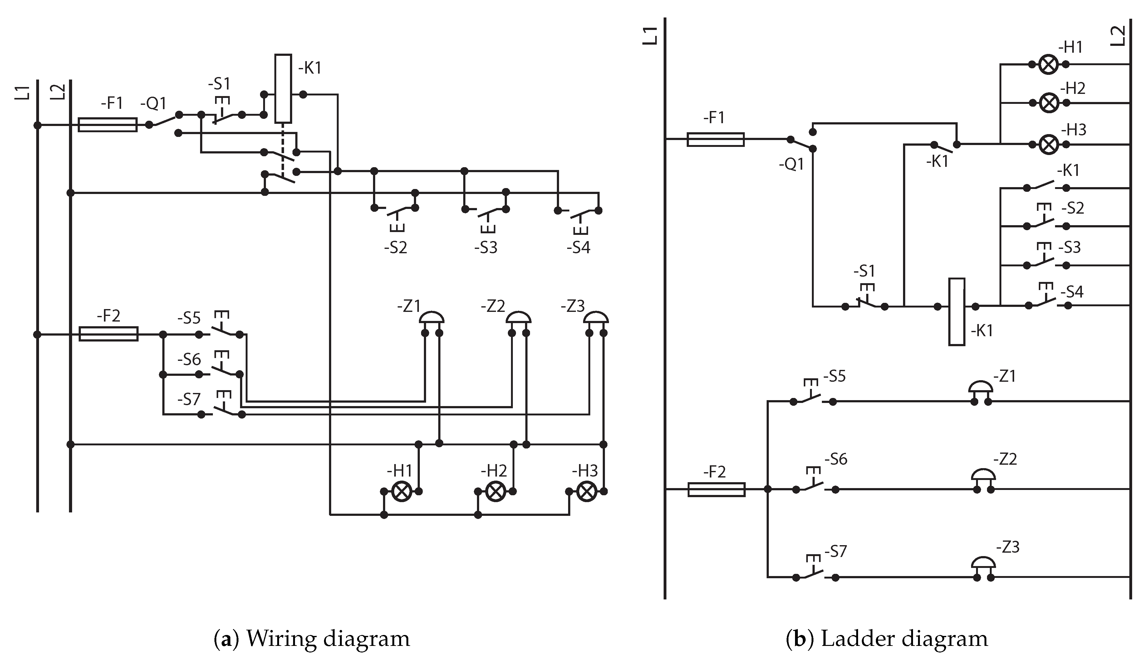
Engineers are required to master both types of diagrams when designing an electrical system. Thus, one of the main goals of the Industrial Design subject is to teach engineering students the abilities required to convert a wiring diagram into a ladder one. The process is highly mechanical, with some basic rules like: (i) conductors are represented using horizontal or vertical lines; (ii) there are exactly the same number of elements in both diagrams; (iii) conductors cannot be crossed in ladder diagrams, or (iv) in ladder diagrams, elements of the same component can be placed separately (e.g., switches and coil in a relay) however, in wiring ones they must be placed together, etc.. Figure 1a,b shows an example of each type of diagram of a simple circuit. Figure 1a shows the wiring diagram of an electrical circuit. The operation of the system is hardly understandable until every connection is thoroughly checked, even though it is a very simple system. However, the relative physical location is noticed at first glance. Figure 1b represents the ladder diagram of the wiring one explained above. This diagram graphically explains the dependencies between components of the circuit and its operation. There is one horizontal line for each set of dependent elements. In this specific diagram, there is no clue about the physical location of components nor their relative distances. However, we can easily check the functionality of the circuit, and the dependencies between components. In the displayed circuit, there are two different ways for turning on the three lamps. On the one hand, changing the position of Commuter Q1, directly activates all the lamps. They turn off changing Q1 to its original state. On the other hand, we can observe that when any of the three push buttons S2, S3, or S4 are pressed, the relay K1 is excited and its two associated switches change their state. One of them turns on the three lamps H1, H2, and H3, and the other switch serves as feedback mechanism that keeps the relay excited, so that the lamps keep on until S1 is pressed. Additionally, there are also three bells Z1, Z2, and Z3 each of them with an associated push button S5, S6, and S7, respectively.
The transformation of the wiring diagram into a ladder one is direct if specific rules are applied. However, most of the engineering students, in their early years at university, are not very familiar with the basics of electricity and find difficulties in understanding the process. Existing commercial software tools are either graphical tools for creating good-looking diagrams but with no functionality, or very complex software for designing real installations, able to integrate different aspects in the same model. Next, we present some of the most relevant software tools available in the literature for creating and designing electrical systems.
3. Literature Review
There is a large list of commercial software available in the market for creating electric diagrams, or for designing electrical systems, at different prices. They can be basically divided in two categories. The first one offers an easy-to-use and fast software tool for creating good-looking diagrams ready to print, with no functionality, and requires the experience and knowledge of the user for ensuring the correctness of the diagram. The second category includes those tools for the professional design of electrical systems with actual simulation and validation for finding inconsistencies in the system. The most advanced ones also provide a collaborative environment in real time with other disciplines such as mechanics or automation. Next, we briefly mention some of the most relevant software tools in both categories.
3.1. Software Tools for Drawing Electrical Diagrams
Dan Wade created EZ Schematics [17], an easy-to-use software that allows development and printing of electrical schematics or wiring diagrams that look professional. It is equipped with different symbol libraries based on the standards released by the National Electrical Manufacturers Association (NEMA) or the ones included in the International Electrotechnical Commission (IEC), such as single-pole brakes, pushbuttons, or fuses. It also includes 3 phase symbols, hydraulic valves, or actuators. Additionally, the software allows creating custom symbols.
Edraw Max [18] is a visualization software that gives professional-looking charts, mind maps, UML diagrams, and electrical engineering diagrams. It provides more than 2000 electrical symbols to create and present electrical diagrams in an easy and fast way with good-looking.
Electra E8 [19] is an easy and intuitive electrical CAD software for creating circuits, and provides more than 700 standardized symbols that can be transformed into many more. It is based on Microsoft Visio, thus, familiar to anyone using Microsoft Office.
3.2. Software Tools for Designing Electrical Systems
The Constructor [20] is an electrical software program that not only allows creation and printing of ladder diagrams, diagram schematics, and one-line diagrams in a fast an easy way, but also provides testing and troubleshooting thanks to the functionality of circuit simulation. This capability is crucial for narrowing down problems in early stages, before hard wiring in the field. It can simulate simple, complex, and even three-phase wiring diagrams. It has over 800 symbols including NEMA and IEC control/power symbols along with various graphic, electronic, and one-line symbols.
Automation Studio P6 professional edition offers a powerful solution for electrical systems design [21] and providing analysis, diagnostic, and validation tools for detecting errors and inconsistencies. It fully supports IEC and NEMA standards and allows the customization of symbols. It also includes a black box representation that stands in for a complex component only by its contour. It is a multi-user environment, allowing the safe sharing of the project and linking of external processes to other corporate applications.
Elecworks [22] is an electrical CAD software for designing electrical installations and automation projects. It has a large schematic library of standard symbols that can be marked, edited. Its terminals can even be numbered, and it also supports the black box representation. It allows both single and multi-line schematic drawing. One of the main features of Elecworks is the possibility of collaborative working in real time. Elecworks offers a complete integration, so that electricians and mechanics can work together on the same digital model, either in 2D or with the 3D project model.
From the educational point of view, although these existing software tools can be useful for other purposes, they are not adequate for our case. The main reason is that none of the existing tools convert the electrical wiring diagram into the ladder one, and vice versa which is the main concept students must acquire. Therefore, a custom software that not only converts one type of diagram into another but also allows the self-assessment of students is required.
4. CAD Tool for Electrical Diagrams—CADDi
Engineering students acquire different competences during their studies. They learn skills such as graphical representation, creation, and understanding of technical drawing or any type of plan like, mechanical drawing, electronic drawing, topography or electric diagrams. In the early years of their studies at the university, they are not familiarized with electricity yet, and they find difficulties in understanding this topic. Additionally, there is a lack of available resources in this specific issue. Students can hardly find and test their competences at home by themselves.
As it was already mentioned in Section 3, in the literature we can find either tools for creating professional-looking electric diagrams and/or circuits ready to print and show off but with no functionalities nor certainty of correctness, or very powerful professional tools for advanced systems design, available for users with strong background and knowledge on electricity.
In this work, we are introducing CADDi, a computer-aided design tool that allows students to code using a specific programming language for wiring diagrams, very easy to understand and intuitive (explained next in Section 5), and it automatically checks its correctness and if so transforms it into the corresponding ladder diagram. Additionally, it is possible to simulate the diagrams and check the behavior of the circuit. For example, if we do a mouse click over push buttons, they change their state, allowing the electricity to run over the circuit, or preventing that (e.g., they close if they were opened or open if they were closed). If the push button was serving a lamp it will light up, or if it was a bell it will change to a ringing state.
To the best of our knowledge, CADDi is the first CAD tool able to create wiring diagrams, ensure correctness, and transform them into ladder ones. It has been specifically designed for teaching purposes. It has several advantages that make it especially helpful for engineering students:
- it is a homework support tool because students have difficulties in finding solved exercises where both the wiring and its correspondent ladder diagram appear;
- it is a self-assessment tool because students can check if the solution they propose of the ladder diagram that corresponds to a specific wiring diagram is correct or not;
- accessibility, as it has been implemented as a web page so that there is no need for software installation, operative system incompatibilities, or hardware requirements, further than what most devices offer;
- friendly graphical user interface.
5. A Specific Programming Language for Wiring Diagrams—WDLang
WDLang, standing for Wired Diagrams Language is a simple, intuitive, easy-to-use, highly expressive, unequivocal, and correct programming language. The language is formally defined through the context free grammar described using the Backus-Naur (BNF) notation in Table 1, where terminals are represented between quotation marks, and 1* means that what follows is repeated one or more times. The idea behind WDLang is defining every single element composing the electrical diagram and its connections. The list of available elements is given in Table 2, together with their label in WDLang (in ID column), their number of connections, and the symbol representing them, according to the UNE-EN ISO 10209:2012 standard [14]. A circuit is simply encoded as a sequence of components, each in a different line. With the intention of defining a simple language that can be quickly learned by the user, WDLang does not define any functions, loops, variables, or methods. In WDLang, instructions are used to describe the components of the circuit. Every component and electrical node in the wiring diagram must be identified by the programmer, and instructions must include (i) the label of the component, as shown in Table 2, (ii) a unique identifier of the element, and (iii) the list of electrical nodes it is connected to. Therefore, an instruction defining some specific component will be represented as follows:
where , , and are unique identifiers (i.e., numbers) for the element and the electrical nodes (or connections), respectively.
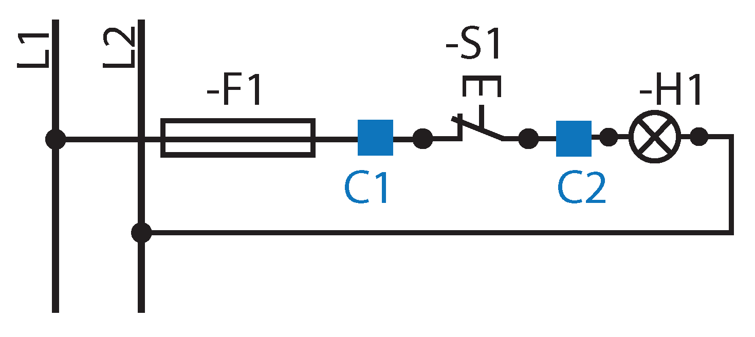
We show in Figure 2a simple electrical circuit, and how it can be encoded in WDLang. The circuit is composed by three components, namely a fuse, a push button opening, and a lamp. These elements are tagged as F1, S1, and H1, respectively, according to UNE-EN ISO 10209:2012 standard [14]. Because the standard tags different elements of the same category with the same labels, we need to define specific labels for every component in WDLang. These elements are defined in WDLang as F, SO, and H, respectively. The fuse is connected to L1 and C1, the push button is between C1 and C2, and the lamp is linked to C2 and L2. Therefore, the circuit would be represented in WDLang as:
| F1(L1, C1) | // The fuse (F1) |
| SO1(C1, C2) | // The push button opening (S1) |
| H1(C2, L2) | // The lamp (H1) |
As it can be seen in Table 2, all components have 2 connectors but:
- Commuter: it has three terminals.
- Relay: it can have between 4 and 18 terminals. The first two terminals are the power input and output of the relay. The rest are the terminals of its switches. A relay can have from 1 to 8 switches.
- Relay with automatic connection and relay with automatic disconnection: they have the same connections as the regular relay.
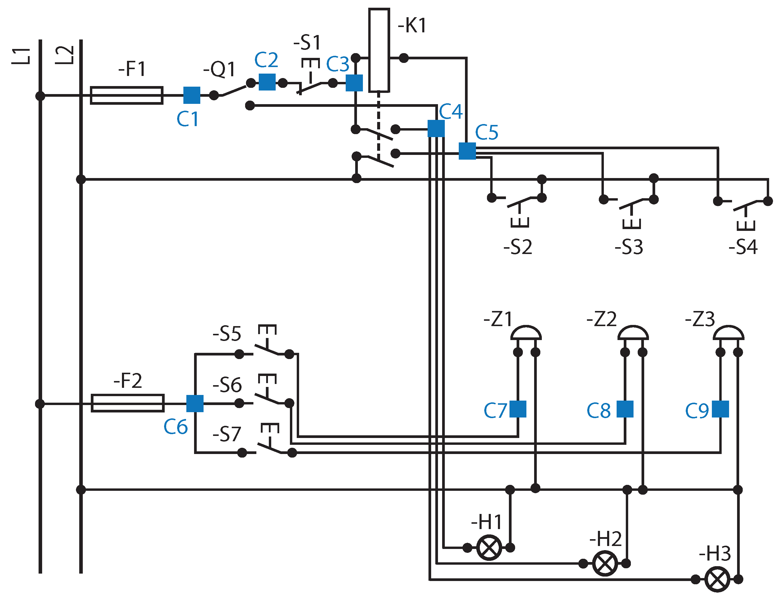
To better explain the composition of the instructions required by WDLang, we have included in Figure 3 the same wiring diagram of the example presented in Figure 1a, but where all the electrical nodes of the circuit have been uniquely identified.
We present in Algorithm 1 the code corresponding to the sample diagram displayed in Figure 1 and Figure 3. As it can be seen, instructions start by the type of the element, followed by its unique identifier (which is set in this example to the same one as the label in the displayed diagram). Therefore, Algorithm 1 means that Commuter ‘SW1’ (tagged as Q1 in the diagram) is connected to cables ‘C1’, ‘C2’ and ‘C4’, where ‘H1’,‘H2’, and ‘H3’, as well as one of the associated switches of ‘K1’, are connected too. Comments can be added as in C language: either writing ‘//’ at the beginning of the line, or enclosing several consecutive lines between ‘/*’ and ‘*/’.
| Algorithm 1 Sample code for the diagram in Figure 1a. |
| 1: F1(L1, C1) // Fuse F1 |
| 2: SW1(C1, C2, C4) // Commuter Q1 |
| 3: SO1(C2, C3) // Push button opening S1 |
| 4: KM1(C3, C5, C3, C4, C5, L2) /* Relay K1, with two |
| 5: associated contacts */ |
| 6: SC2(C5, L2) // 3 push buttons closing: S2, S3, S4, connected in parallel |
| 7: SC3(C5, L2) |
| 8: SC4(C5, L2) |
| 9: F2(L1, C6) // Fuse F2 |
| 10: SC5(C6, C7) // 3 bells (Z1, Z2, Z3) connected to 3 push buttons (S5, S6, S7) |
| 11: SC6(C6, C8) |
| 12: SC7(C6, C9) |
| 13: Z1(C7, L2) |
| 14: Z2(C8, L2) |
| 15: Z3(C9, L2) |
| 16: H1(C4, L2) // Three lamps, H1, H2, H3, connected in parallel |
| 17: H2(C4, L2) |
| 18: H3(C4, L2) |
6. Graphical Interface of CADDi
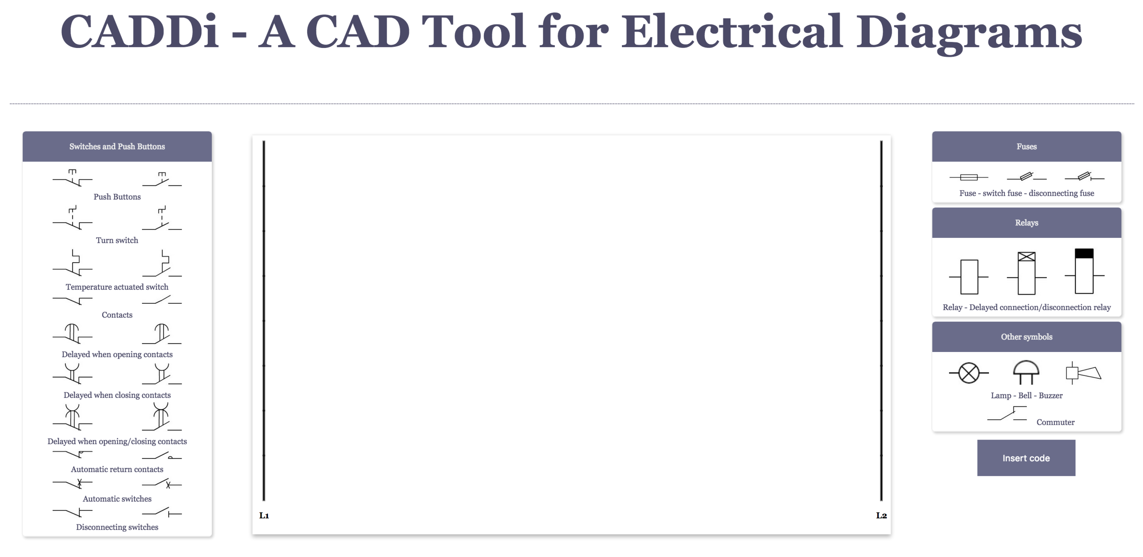
Accessibility was a strong requirement in our design. When we first planned the implementation of an electrical software tool, we considered it was essential to be hardware and operative system independent. No installations required. Thus, CADDi was conceived as a web site.
Figure 4 shows a screenshot of the website of CADDi. It was implemented using JointJS library [23], which offers an extensive API to build advanced HTML 5 applications. This library allows visualization and interaction with diagrams and it is highly event driven, thus reactions to events happening inside the paper are possible. As already mentioned in Section 4 push buttons, commuters, and switches can be activated and or deactivated with simple mouse clicks, consequently modifying the flow of electricity in the circuit, so its operation is visualized.
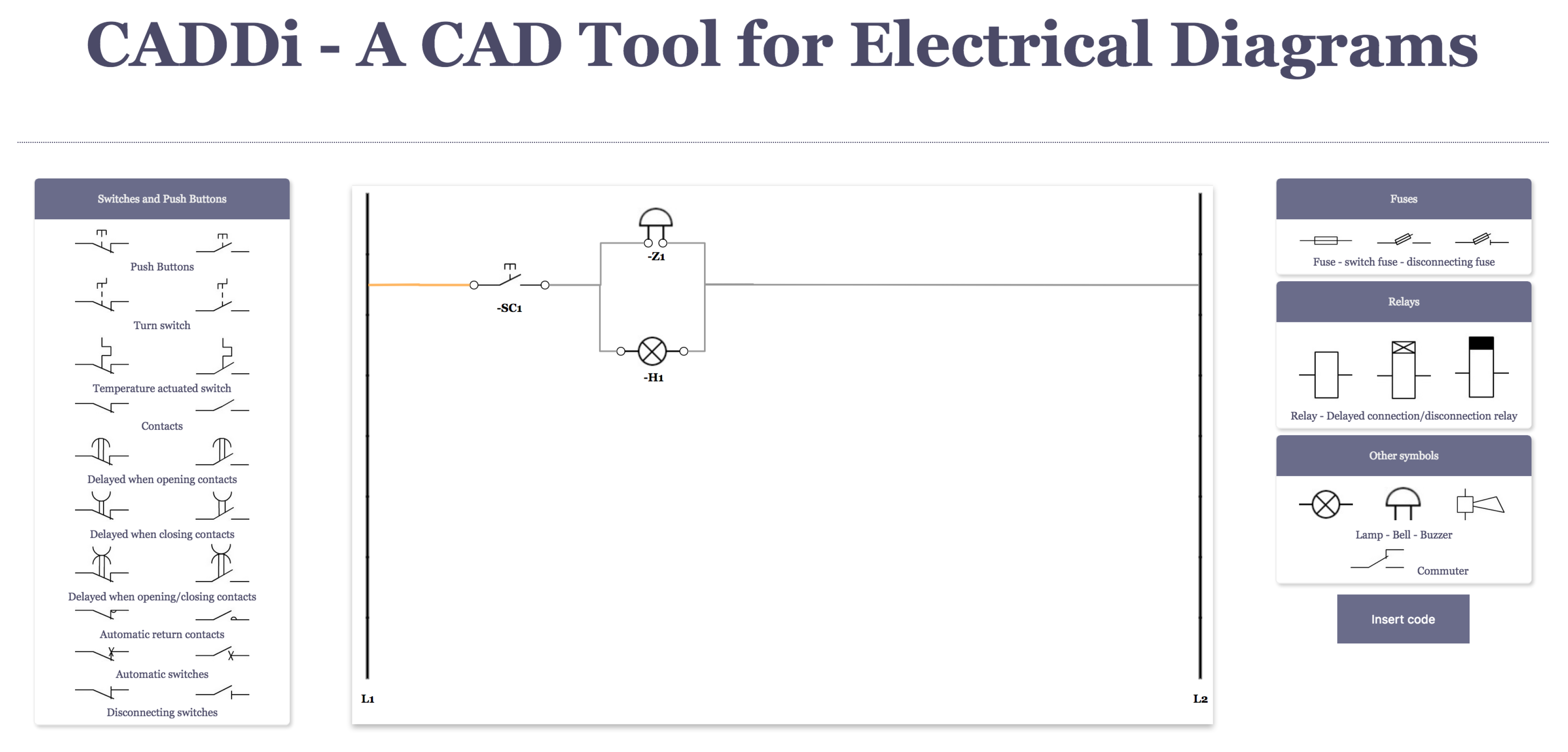
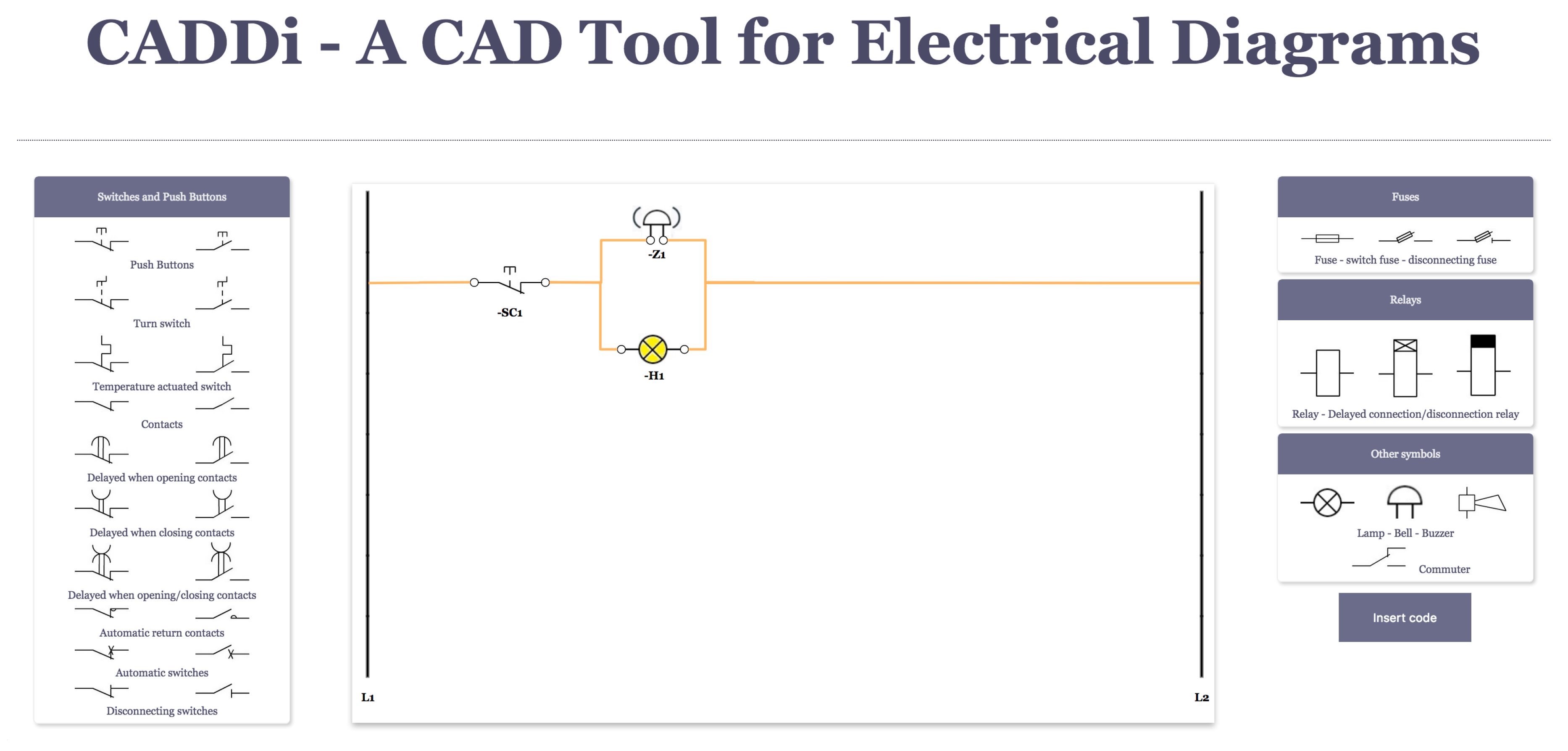
Figure 5 and Figure 6 show an example of how the operation of the circuit is represented. A basic diagram where a push button activates a bell and a lamp when pressed is drawn. The initial state is represented in Figure 5 and when a mouse click is done over the push button it changes state (for a predefined time) and allows the circulation of the electricity, turning on then, the lamp and the bell, as seen in Figure 6.
There are two operation modes in CADDi. On the one hand, it is possible to create a ladder diagram directly on the canvas by clicking on the available symbols and check its functionality. On the other hand, it is possible to program a wiring diagram using WDLang and automatically convert it into the corresponding ladder diagram. Next, we explain both approaches.
6.1. Creating Ladder Electrical Diagrams with CADDi Graphical User Interface
A large number of the most common used electrical components in educational diagrams are implemented in CADDi. Figure 4 shows a screenshot of the graphical interface of CADDi. Initially, the web site of CADDi offers a plain canvas, with two vertical lines representing L1 and L2, each on one side of the paper. The different symbols that can be used are shown on both the right and the left side of the canvas. A mouse click on a symbol of the menu adds it to the canvas. Symbols can be connected to other symbols, moved, turned, or deleted. To make the connection between components, it is necessary to click on one terminal, L1, or L2, and drag with the mouse to the desired terminal of another component, L1, or L2. Once a connection is established, components can be moved, and their connections remain stable. Dependencies can be also established in CADDi. A relay is composed of a coil and several contacts. When the coil is excited the associated contacts change their states. In order to make this association in CADDi, it is necessary to drag the associated contacts over the coil and release the mouse click. At this moment, the functional dependency is established. It is possible to remove and to turn components from the canvas just by clicking on it with the right button of the mouse. The complete canvas will be cleaned after clicking on it with the right button of the mouse.
6.2. Using WDLang for the Design of Wiring Electrical Diagrams
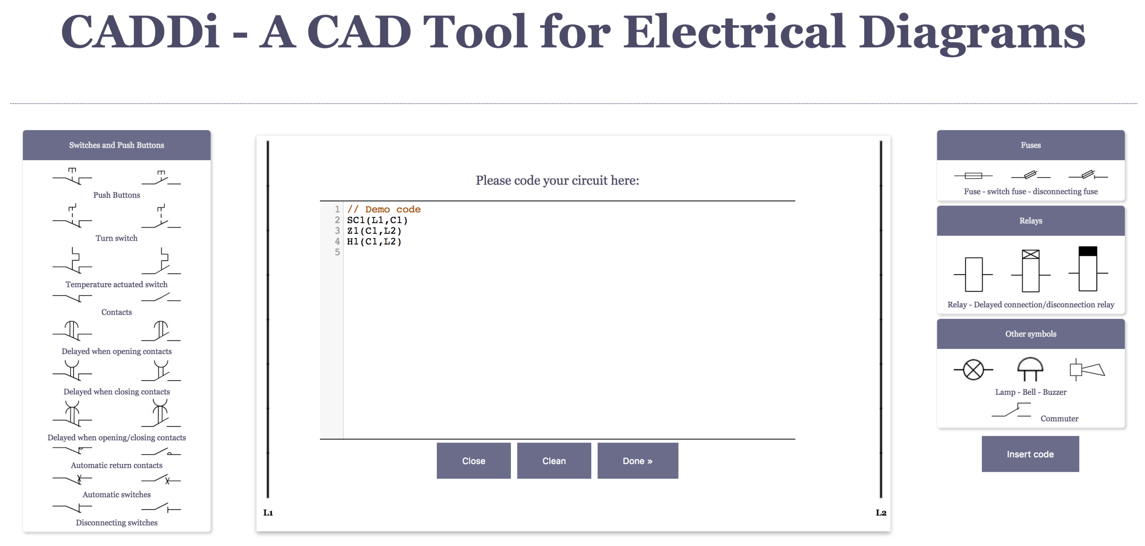
As mentioned before, CADDi has a user interface that directly transforms a wiring diagram into a ladder one. The diagram must be coded using WDLang, as explained in Section 5. The web page offers an insert code button for uploading the file. Then, this code is processed, and the corresponding ladder diagram appears. The diagram can be easily modified, either by adding new elements, deleting some, moving them, or re-routing the wires connecting them. When a component is moved, its connections are kept. This functionality is added for essaying the understanding of the circuit, in case the elements in the automatically generated diagram are not well located. Figure 7 shows a screenshot of how the code is included.
7. Conclusions and Future Work
In this work, we are presenting CADDi and WDLang. The former is a CAD tool for assisting engineering students in understanding basic electrical concepts, creating electric diagrams and transforming wiring into ladder ones. The latter, WDLang, is a new programming language that assists CADDi. The resulting tailored software allows the user to design, create, and simulate electrical diagrams either using the user graphical interface or WDLang. It also provides the possibility of transforming wiring electric diagrams into ladder ones easily. The simplicity of the proposed programming language, WDLang, ensures a fast learning curve and usability.
In future work, we plan to further improve CADDi by defining more electric components, as well as with a tool to allow the design of custom ones. Additionally, it will be very interesting to investigate if CADDi can support triphase diagrams.
Author Contributions
The authors contributed equally to this work.
Funding
The authors would like to thank university of Cádiz that partially funded this work with the educational innovation project sol-201700083122-tra and supported it with projects PR2018-062 and PR2018-056. Bernabé Dorronsoro would like to acknowledge the Spanish Ministerio de Economía, Industria y Competitividad and ERDF for the support provided under contracts TIN2014-60844-R (the SAVANT project) and RYC-2013-13355.
Conflicts of Interest
The authors declare no conflict of interest.
References and Notes
- Du, S.; Wu, Q.; Wang, Y.; Yi, Z. Study of method for computer aided ergonomics knowledge management and design aiming at product design. In Proceedings of the 2009 IEEE 10th International Conference on Computer-Aided Industrial Design & Conceptual Design, Wenzhou, China, 26–29 November 2009; pp. 1176–1180. [Google Scholar]
- Su, J.; Zhang, S. Research on product shape innovation design method with human-computer interaction through genetic algorithm. In Proceedings of the 2010 IEEE 11th International Conference on Computer-Aided Industrial Design & Conceptual Design 1, Yiwu, China, 17–19 November 2010; pp. 301–305. [Google Scholar]
- Rojas-Sola, J.I.; De la Morena-De la Fuente, E. Agustin de Betancourt’s Mechanical Dredger in the Port of Kronstadt: Analysis through Computer-Aided Engineering. Appl. Sci. 2018, 8, 1338. [Google Scholar] [CrossRef]
- Zhong, C.K. The optimal choice of computer-aided design software in modern industrial design. In Proceedings of the 2010 IEEE 11th International Conference on Computer-Aided Industrial Design & Conceptual Design 1, Yiwu, China, 17–19 November 2010; pp. 153–155. [Google Scholar]
- Kim, Y.-J.; Heo, J.-Y.; Hong, K.-H.; Lim, B.-Y.; Lee, C.-S. Computer-Aided Design and Manufacturing Technology for Identification of Optimal Nuss Procedure and Fabrication of Patient-Specific Nuss Bar for Minimally Invasive Surgery of Pectus Excavatum. Appl. Sci. 2019, 9, 42. [Google Scholar] [CrossRef]
- Najjar, A.; Platzer, C.; Luft, A.; Abmann, C.A.; Elghazawy, N.H.; Erdmann, F.; Sippl, W.; Schmidt, M. Computer-aided design, synthesis and biological characterization of novel inhibitors for PKMYT1. Eur. J. Med. Chem. 2019, 161, 479–492. [Google Scholar] [CrossRef] [PubMed]
- Cavas-Martínez, F.; Fernández-Pacheco, D.G.; Cañavate, F.J.F.; Velázquez-Blázquez, J.S.; Bolarín, J.M.; Alió, J.L. Study of Morpho-Geometric Variables to Improve the Diagnosis in Keratoconus with Mild Visual Limitation. Symmetry 2018, 10, 306. [Google Scholar] [CrossRef]
- Chang, Y.-S.; Chen, M.Y.; Chuang, M.-J.; Chou, C.-H. Improving creative self-efficacy and performance through computer-aided design application. Think. Skills Creat. 2019, 31, 103–111. [Google Scholar] [CrossRef]
- Liu, J.; Guo, W. A teaching model of spatial design by computer-aided design. In Proceedings of the 2009 IEEE 10th International Conference on Computer-Aided Industrial Design & Conceptual Design, Wenzhou, China, 26–29 November 2009; pp. 831–835. [Google Scholar]
- Salman, H.S.; Laing, R.; Conniff, A. The impact of computer aided architectural design programs on conceptual design in an educational context. Des. Stud. 2014, 35, 412–439. [Google Scholar] [CrossRef] [Green Version]
- Heskett, J. Industrial Design; World of Art; Thames and Hudson: London, UK, 1980. [Google Scholar]
- Turbak, F.; Gifford, D. Design Concepts in Programming Languages; The MIT Press: Cambridge, MA, USA, 2008. [Google Scholar]
- Watt, D.A. Programming Language Design Concepts; Wiley: Hoboken, NJ, USA, 2006. [Google Scholar]
- International Organization for Standardization. ISO 10209:2012 Technical Product Documentation—Vocabulary—Terms Relating to Technical Drawings, Product Definition and Related Documentation. 11.52.1 Diagram. 2012.
- International Organization for Standardization. ISO 10209:2012 Technical Product Documentation—Vocabulary—Terms Relating to Technical Drawings, Product Definition and Related Documentation. 8.12 Graphical Symbol. 2012.
- International Organization for Standardization. ISO 14617. Graphical Symbols for Diagrams. 2005.
- Wade Instruments and Service, Inc. EZ Schematics. Available online: http://www.wadeinstruments.com/ez_schematics/description.htm (accessed on 23 February 2019).
- EdrawSoft. Electrical Schematics Sketching Software. Available online: https://www.edrawsoft.com/electrical.php (accessed on 23 February 2019).
- Radica Software. Electra E8. Available online: https://radicasoftware.com/index.php (accessed on 23 February 2019).
- CMH Software, Inc. The Constructor. Available online: https://www.cmhsoftware.com/constructor.html (accessed on 23 February 2019).
- Famic Technologies Inc. Automation Studio P6 Professional Edition. Available online: https://www.famictech.com/pro/Electrical.html (accessed on 23 February 2019).
- Trace Software International. Elecworks. Available online: http://www.trace-software.com/elecworks/electrical-cad-software-advantages (accessed on 23 February 2019).
- JointJS Library. Available online: https://www.jointjs.com (accessed on 23 February 2019).
Figure 1.
Example of a simple wiring diagram (a) and its corresponding ladder diagram (b).

Figure 2.
Example of identification of a simple wiring diagram.

Figure 3.
Example of a wiring diagram with electric nodes identified.

Figure 4.
Graphical interface of CADDi.

Figure 5.
Basic diagram with a lamp and a bell not activated.

Figure 6.
Basic diagram with a lamp and a bell activated.

Figure 7.
Example of the code for a basic electrical diagram. It is composed of a switch that activates a relay turning on a lamp.
Figure 7.
Example of the code for a basic electrical diagram. It is composed of a switch that activates a relay turning on a lamp.


Table 1.
Grammar defining WDLang, in Backus-Naur Form (BNF). Uppercase names correspond to tokens (or terminal symbols), while the rest are variables (or non-terminal symbols).
Table 1.
Grammar defining WDLang, in Backus-Naur Form (BNF). Uppercase names correspond to tokens (or terminal symbols), while the rest are variables (or non-terminal symbols).
| circuit::= component 1*{\n} components | |
| components::= [component 1*{\n} components] | |
| component::= element2connectors “(” connector “,” connector “)” | |
| | “X”1*{DIGIT} “(” connector “,” connector [“,” “ground”] “)” | ; Plug |
| | “SW”1*{DIGIT} “(” connector “,” connector “,” connector “)” | ; Commuter |
| | element4to18Connectors “(” connector “,” connector “,” connector “,” connector [“,” connector “,” connector [“,” connector | |
| “,” connector [“,” connector “,” connector [“,” connector “,” connector [“,” connector “,” connector [“,” connector | |
| “,” connector [“,” connector “,” connector]]]]]]] “)” | |
| element2connections::= “H”1*{DIGIT} | ; Lamp |
| | “SO”1*{DIGIT} | ; Push button opening |
| | “SC”1*{DIGIT} | ; Push button closing |
| | “SBO”1*{DIGIT} | ; Turn switch opening |
| | “SBC”1*{DIGIT} | ; Turn switch closing |
| | “FSO”1*{DIGIT} | ; Temperature actuated switch opening |
| | “FSC”1*{DIGIT} | ; Temperature actuated switch closing |
| | “QO”1*{DIGIT} | ; Contact opening |
| | “QC”1*{DIGIT} | ; Contact closing |
| | “SODC”1*{DIGIT} | ; Delayed connection contact closing |
| | “SCDC”1*{DIGIT} | ; Delayed connection contact opening |
| | “SODD”1*{DIGIT} | ; Delayed disconnection contact closing |
| | “SCDD”1*{DIGIT} | ; Delayed disconnection contact opening |
| | “SODCD”1*{DIGIT} | ; Delayed connection/disconnection contact closing |
| | “SCDCD”1*{DIGIT} | ; Delayed connection/disconnection contact opening |
| | “QCO”1*{DIGIT} | ; Automatic return contact closing |
| | “QCC”1*{DIGIT} | ; Automatic return contact closing |
| | “QAO”1*{DIGIT} | ; Automatic switch opening |
| | “QAC”1*{DIGIT} | ; Automatic switch closing |
| | “QDO”1*{DIGIT} | ; Automatic disconnection switch opening |
| | “QDC”1*{DIGIT} | ; Automatic disconnection switch closing |
| | “F”1*{DIGIT} | ; Fuse |
| | “FS”1*{DIGIT} | ; Switch fuse |
| | “FD”1*{DIGIT} | ; Disconnection fuse |
| | “Z”1*{DIGIT} | ; Bell |
| | “PJ”1*{DIGIT} | ; Buzzer |
| | “D”1*{DIGIT} | ; Sensor |
| | “B”1*{DIGIT} | ; Motion sensor |
| | “E”1*{DIGIT} | ; Electric lock |
| elements4to18Connectors::= “KM”1*{DIGIT} | ; Relay |
| | “KAC”1*{DIGIT} | ; Relay automatic delayed disconnection |
| | “KAD”1*{DIGIT} | ; Relay automatic delayed connection |
| connector::= L1 | |
| | L2 | |
| | “ground” | |
| | “C”1*{DIGIT} | ; Cables connector |
| DIGIT::= “0”|“1”|“2”|“3”|“4”|“5”|“6”|“7”|“8”|“9” | |
Table 2.
Available symbols in CADDi, their corresponding identifiers and number of terminals, as defined in WDLang.
Table 2.
Available symbols in CADDi, their corresponding identifiers and number of terminals, as defined in WDLang.
| Component | ID | Connections | Symbol | Component | ID | Connections | Symbol |
|---|---|---|---|---|---|---|---|
| Push Button Opening | SO | 2 |  | Automatic Switch Closing | QAC | 2 |  |
| Push Button Closing | SC | 2 |  | Automatic Disconnecting Switch Opening | QDO | 2 |  |
| Turn Switch Opening | SBO | 2 |  | Automatic Disconnecting Switch Closing | QDC | 2 |  |
| Turn Switch Closing | SBC | 2 |  | Fuse | F | 2 |  |
| Temperature Actuated Switch Opening | FSO | 2 |  | Switch Fuse | FS | 2 |  |
| Temperature Actuated Switch Closing | FSC | 2 |  | Disconnecting Fuse | FD | 2 |  |
| Contact Opening | QO | 2 |  | Relay | KM | [4, 18] |  |
| Contact Closing | QC | 2 |  | Relay with Automatic Delayed Connection | KAC | [4, 18] |  |
| Delayed Connection Contact Opening | SODC | 2 |  | Relay with Automatic Delayed Disconnection | KAD | [4, 18] |  |
| Delayed Connection Contact Closing | SCDC | 2 |  | Bell | Z | 2 |  |
| Delayed Disconnection Contact Opening | SODD | 2 |  | Buzzer | PJ | 2 |  |
| Delayed Disconnection Contact Closing | SCDD | 2 |  | Lamp | H | 2 |  |
| Delayed Connection/Disconnection Contact Opening | SODCD | 2 |  | Commuter | SW | 3 |  |
| Delayed Connection/Disconnection Contact Closing | SCDCD | 2 |  | Plug | X | {2,3} |  |
| Automatic Return Contact Opening | QCO | 2 |  | Sensor | D | 2 |  |
| Automatic Return Contact Closing | QCC | 2 |  | Motion sensor | B | 2 |  |
| Automatic Switch Opening | QAO | 2 |  | Electric lock | E | 2 |  |
© 2019 by the authors. Licensee MDPI, Basel, Switzerland. This article is an open access article distributed under the terms and conditions of the Creative Commons Attribution (CC BY) license (http://creativecommons.org/licenses/by/4.0/).
Share and Cite
MDPI and ACS Style
Ruiz, P.; Dorronsoro, B. A Novel CAD Tool for Electric Educational Diagrams. Appl. Sci. 2019, 9, 810. https://doi.org/10.3390/app9040810
AMA Style
Ruiz P, Dorronsoro B. A Novel CAD Tool for Electric Educational Diagrams. Applied Sciences. 2019; 9(4):810. https://doi.org/10.3390/app9040810
Chicago/Turabian StyleRuiz, Patricia, and Bernabé Dorronsoro. 2019. "A Novel CAD Tool for Electric Educational Diagrams" Applied Sciences 9, no. 4: 810. https://doi.org/10.3390/app9040810
Note that from the first issue of 2016, this journal uses article numbers instead of page numbers. See further details here.