Article

Optimal Non-Integer Sliding Mode Control for Frequency Regulation in Stand-Alone Modern Power Grids

by
Zahra Esfahani
1,
Majid Roohi
2,
Meysam Gheisarnejad
3,
Tomislav Dragičević
4 and
Mohammad-Hassan Khooban
5,*
1
Department of Electrical Engineering, University College of Rouzbahan, Sary 3994548179, Iran
2
School of Economics and Statistics, Guangzhou University, Guangzhou 510006, China
3
Department of Electrical Engineering, Najafabad Branch, Islamic Azad University, Isfahan 8514143131, Iran
4
Department of Energy Technology, Aalborg University, DK-9220 Aalborg East, Denmark
5
Department of Engineering, Aarhus University, 8200 Aarhus N, Denmark
*
Author to whom correspondence should be addressed.
Appl. Sci. 2019, 9(16), 3411; https://doi.org/10.3390/app9163411
Submission received: 28 June 2019 / Revised: 9 August 2019 / Accepted: 9 August 2019 / Published: 19 August 2019
(This article belongs to the Special Issue Microgrids)

Abstract

:
In this paper, the concept of fractional calculus (FC) is introduced into the sliding mode control (SMC), named fractional order SMC (FOSMC), for the load frequency control (LFC) of an islanded microgrid (MG). The studied MG is constructed from different autonomous generation components such as diesel engines, renewable sources, and storage devices, which are optimally planned to benefit customers. The coefficients embedded in the FOSMC structure play a vital role in the quality of controller commands, so there is a need for a powerful heuristic methodology in the LFC study to adjust the design coefficients in such a way that better transient output may be achieved for resistance to renewable sources fluctuations. Accordingly, the Sine Cosine algorithm (SCA) is effectively combined with the harmony search (HS) for the optimal setting of the controller coefficients. The Lyapunov function based on the FOSMC is formulated to guarantee the stability of the LFC mechanism for the test MG. Finally, the hardware-in-the-loop (HIL) experiments are carried out to ensure that the suggested controller can suppress the frequency fluctuations effectively, and that it provides more robust MG responses in comparison with the prior art techniques.

Graphical Abstract

1. Introduction

Over the past decade, the reduction of conventional fossil fuel reserves, along with the environmental concerns about their burning, have led to the paradigm change toward the development of renewable energy sources (RESs), such as photovoltaic (PV) and wind turbine generator (WTG) systems penetrating into the power grid [1,2,3]. The planning and exploitation of RESs through distributed generators (DGs) offers the benefits of local generation according to the needs of consumers, with a consequent minimization in the transmission loss. The DGs can be potentially implemented for improving power quality and service reliability [4,5,6,7,8].
A microgrid is regarded as a regulated entity in the power plant and consists of various DGs such as microsources, energy reserve devices, and loads which are locally integrated into the grid for the profit of the customers. Normally, microgrids (MGs) can work in the stand-alone mode as independent islands or grid-connected modes in conjunction with the main electrical grid [9,10,11]. In the grid-connected mode, the main utility generators are responsible for power balance management in connection with new demands. In the isolated operation, the DGs are exposed to the load variations and randomness characteristics of renewable sources, which threaten the grid’s stability. The inherent weakness of the integrated power plants may be somewhat shorted out by the installation of backup systems such as microturbines and energy storage systems (ESSs) [12,13].
Since load frequency control (LFC) capacity is not sufficient to meet all of the control objectives of the microgrid, employing a supplementary regulator in a secondary loop is obligatory. To deal with the secondary LFC control of an islanded MG, the conventional proportional integral derivative (PID) controllers and their variants are capable of restoring frequency deviations in normal operation; however, they cannot work appropriately as operation points of the grid vary remarkably during a daily cycle. To improve the efficiency of the LFC, some suitable control strategies including H∞ control theory [7], adaptive control [14], robust control [15], and model predictive control (MPC) [16] have been applied to the DGs of the hybrid MG. In this regard, an MPC-based coordinated control of the blade pitch angles of the wind turbine (WT), and the plug-in hybrid electric vehicle (PHEV), has been developed in [16] for the LFC issue. The authors in [17] proposed a robust controller using linear matrix inequalities to control the frequency in an integrated form of the MG and multi-MG with different DG units. A model-free intelligent proportional integral (PI) controller is suggested in [18] for several configurations of the isolated hybrid RESs/ESSs. The influence of the increased penetration of WTs and MGs on frequency control is investigated in [19], and an advanced hierarchical control methodology is established for the optimal control of the whole system.
The sliding mode control (SMC) is recognized as a prominent model-based approach to handle disturbances, since this design scheme has inherent insensitivity features against the dynamical system uncertainty. The advantages of the SMC are ease of use, quick convergent velocity, and robustness. Up to now, several published works have been done to boost the strength of the SMC by combining it with H∞ control theory [20], fuzzy logic [21] and neural network [22], etc. However, implementing such sophisticated hybrid methodologies is a challenging duty for controller designers. Most recently, similar to the uses of the fractional calculus (FC) concepts in other conventional methodologies [23,24], the fractional order is incorporated for extension of the simple classic version of the SMC, so that the degree of flexibility is enhanced. A few types of studies have been published for the application of the fractional order SMC (FOSMC) in engineering applications [25,26].
In this study, a cooperative combination of the fractional order and SMC scheme is developed and implemented for the grid frequency control in a hybrid MG. The simulation study is accomplished on a complex MG, including various RESs, to indicate the significance of the suggested model-based FOSMC control theory. The classic methodologies, as mentioned earlier, may not be applicable in such circumstances to guarantee the stability of the hybrid power plant. The controller parameters are adjusted automatically by using an effective combination of the Sine Cosine algorithm and harmony search (SCA-HS). Designing the suggested control strategy is based on the model specifications of the components configured in the controlled MG, and thus the time domain design of such a scheme is very valuable. The proposed FOSMC scheme offers superior frequency regulation of MGs, which are composed of numerous DGs and RESs, in comparison with the MPC and conventional SMC approaches. Moreover, the proposed scheme has more robustness, to tackle more uncertainties than the above-mentioned approaches, making it more suitable for practical applications. For investigating the performance and robustness of the suggested model-based FOSMC technique, experimental validation using hardware-in-the-loop (HIL) simulations are also given in this paper.

2. Non-Integer Order Calculus

Definition 1.
The Riemann–Liouville fractional integration of order α of a continuous function f ( t ) is defined by [27]
D α f ( t ) = 1 Γ ( α ) t 0 t f ( τ ) ( t τ ) α 1 d τ
where t 0 is the initial time and Γ ( . ) is the Gamma function, which is defined by Γ ( z ) = t 0 t z 1 e t d t .
Definition 2.
Let m 1 < α m and m N , then the Caputo fractional derivative of order α of a continuous function φ ( t ) : R + R is given by [27]:
D α φ ( t ) = 1 Γ ( m α ) t 0 t φ ( m ) ( τ ) ( t τ ) α m + 1 d τ
Property 1
([28]). For any constant, ξ R we have D α ξ = 0 .
Property 2
([28]). For α ( 0 , 1 ) and   ω ( t ) C m [ 0 , T ] , we have:
D α ( I α ω ( t ) ) = D α ( D α ω ( t ) ) = ω ( t )
Lemma 1.
Suppose that ψ ( t ) C m [ 0 , T ] and α ( 0 , 1 ) . Then,
D α | ψ ( t ) | = s g n ( ψ ( t ) ) D α ψ ( t )
Proof. 
As   α ( 0 , 1 ) , because of Equation (3), one gets:
D α | ψ ( t ) | = 1 Γ ( 1 α ) t 0 t | ψ ( t ) | ( t τ ) α d τ
Besides,   | ψ ( t ) | = s g n ( ψ ( t ) ) . ψ ( t ) , so in Equation (2), one has:
D α | ψ ( t ) | = 1 Γ ( 1 α ) t 0 t s g n ( ψ ( t ) ) ψ ( t ) ( t τ ) α d τ
Theorem 1
([29]). Suppose that for   α ( 0 ,   1 ) , the fractional-order system D α y ( t )   = g ( y ,   t )   satisfies the Lipschitz condition and it has an equilibrium point like   y = 0 . Assume that there exists a Lyapunov function V   ( t ,   y ( t ) ) and class-K functions α 1 ,   α 2 and α 3 satisfying
α 1 ( y ) V   ( t , y ) α 2 ( y )
D p V ( t , y ) α 3 ( y )
which p ( 0 , 1 ) . Then the equilibrium point of the system D α y ( t )   = g ( y ,   t )   is asymptotically stable.
Theorem 2
([30]). Consider the following FO system
D α X = F ( x , t ) .
Let   Λ : ( 0 , ) × [ 0 , X ] R n introduce as
Λ ( ω , t ) = 0 t e ω 2 ( t θ ) F ( x , θ ) d ( θ )
Then, the FO system (8) can be written as
{ Λ ( ω , t ) t = ω 2 Λ ( ω , t ) + F ( x , t ) X ( t ) = 0 u ( ω ) Λ ( ω , t ) d ω
where u ( ω ) = 2 sin ( α π ) π ω 1 2 α , α ( 0 , 1 ) .

3. Description of an Isolated Fractional-Order Microgrid Model

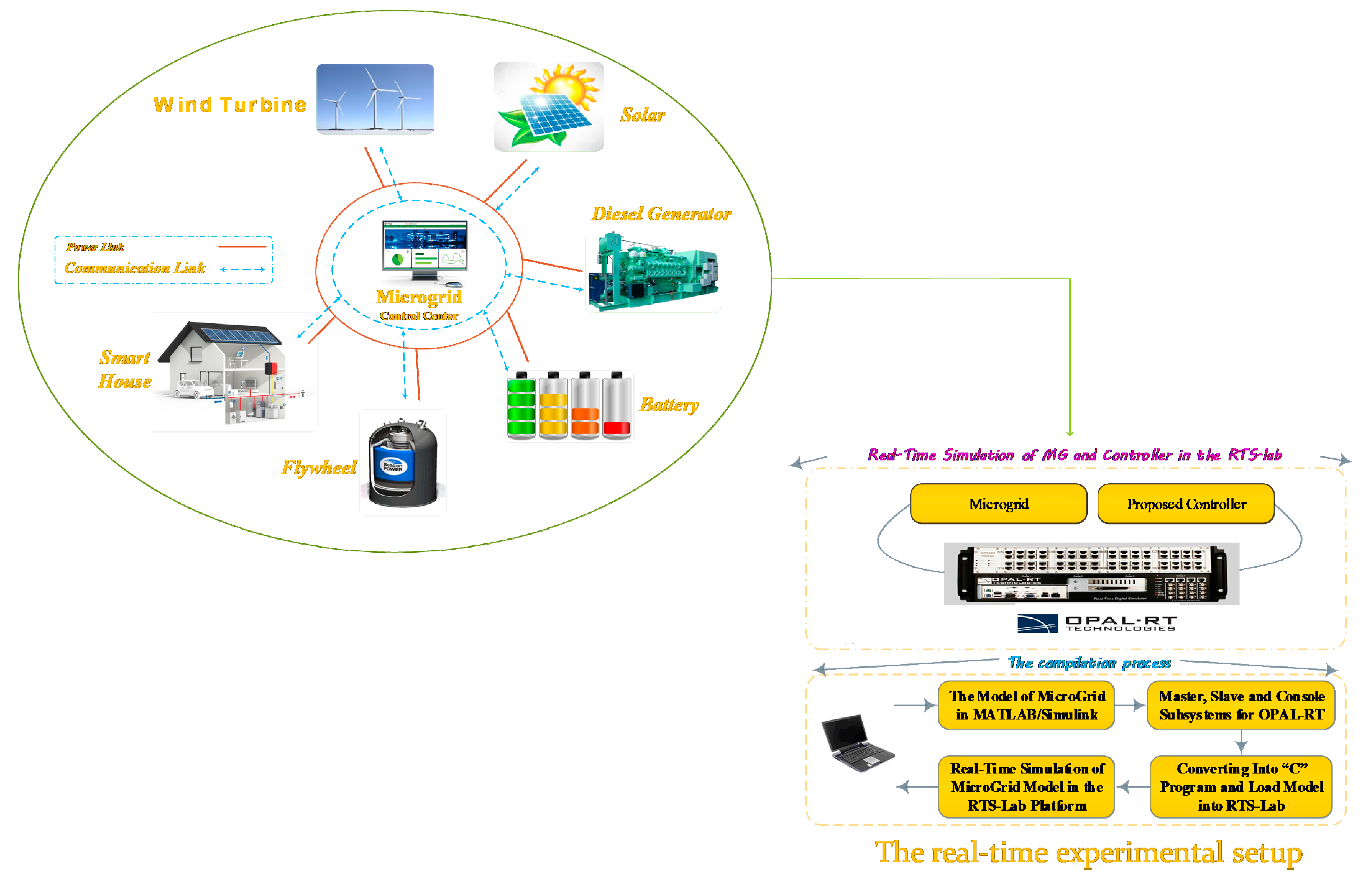
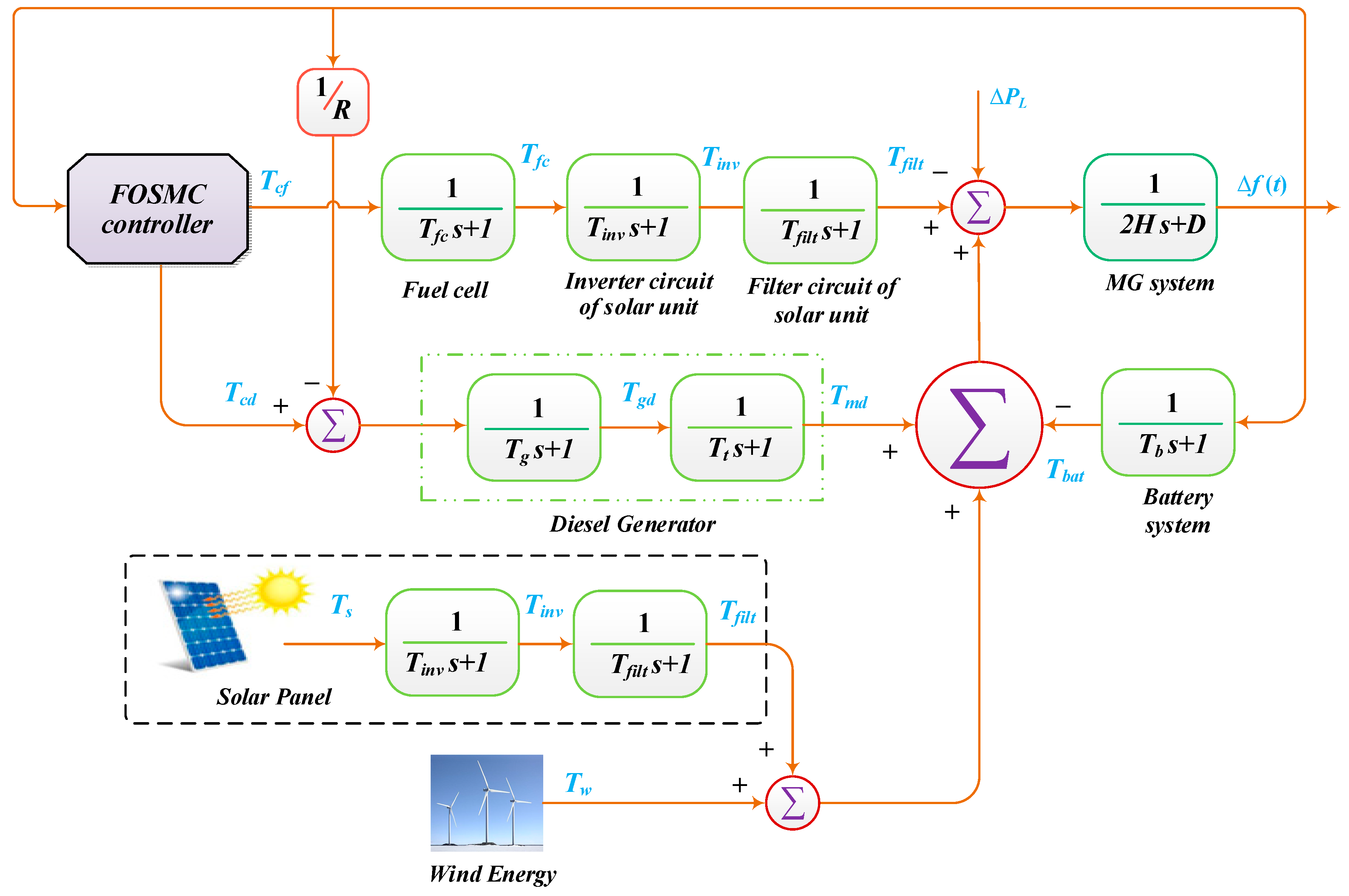
3.1. An Isolated Microgrid

In an isolated MG, the distributed loads are provided by various DG components such as PVs and WTGs, and backup system elements (e.g., battery energy storage system (BESS) and flywheel energy storage system (FESS)) [8,31]. A general scheme of microgrids is illustrated in Figure 1. Usually, the MG dispatch system (MGDS) and the distribution management system (DMS) control the MG operation and the power grid, respectively. Moreover, communication links attain reciprocal information transition.

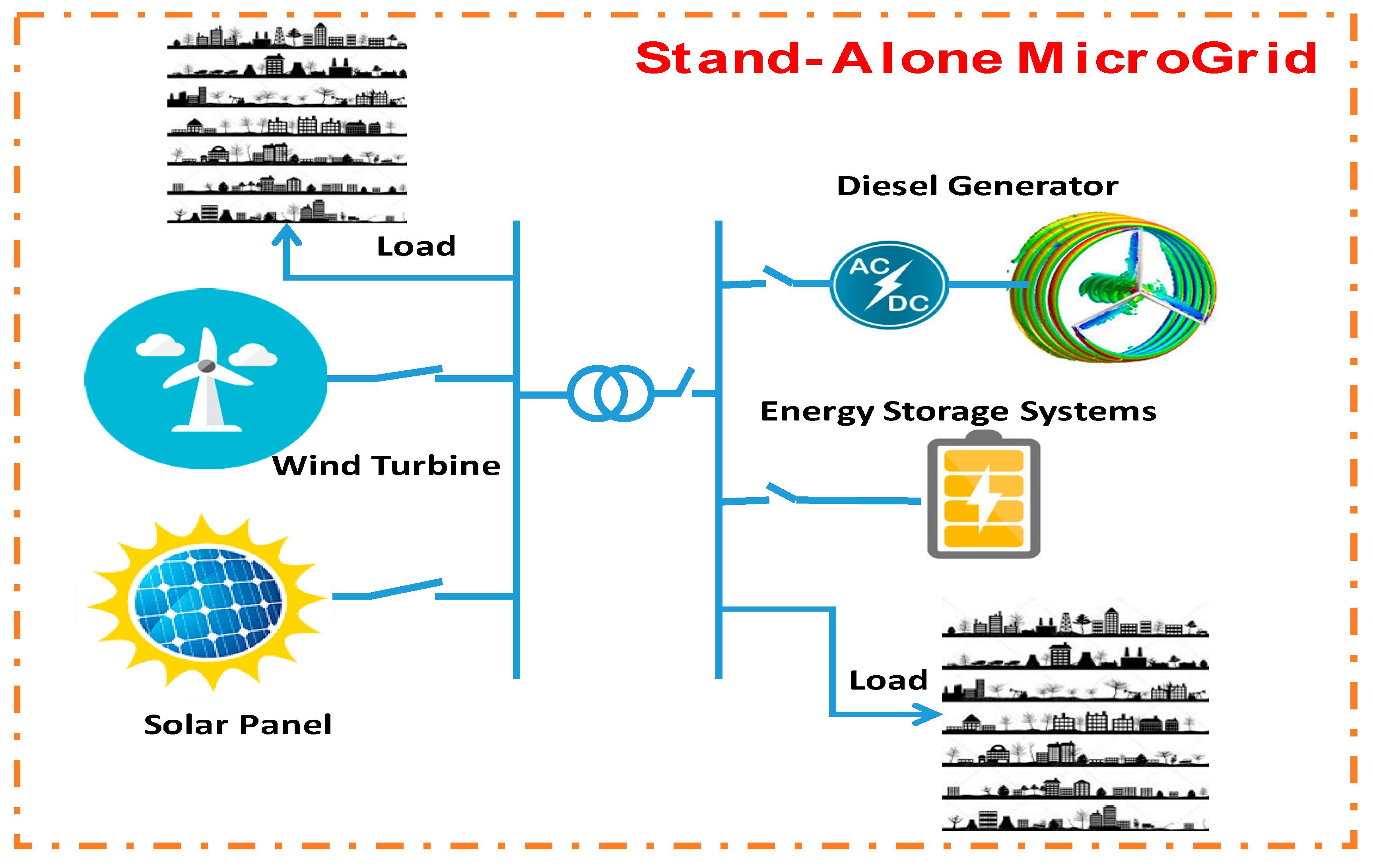
3.2. The Diesel Engine Generator Model

The diesel engine generators (DEGs) have a lot of advantages, such as their fast speed in the start, low maintenance, and high efficiency; hence, they have been a good option for backup in isolated MGs [32]. By precisely regulating the DEG, the changes of load in the MGs can be instantaneously tracked. In addition, the diesel power element can compensate for the fluctuations of renewable DGs (such as WTG, PV, etc.) effectively.
The transfer function of the DEG is illustrated in Figure 2, which describes the control relationship of the DEG output power and the LFC action. As presented in Figure 2, the elements of the governor and generator are represented by the first-order inertia models of inertia term.

3.3. Wind Turbine Generator

The output power of wind turbines depends on the inherent specifications of the turbine, and two factors: The speed and direction of the wind. The controllable WTG can be considered as a power oscillation source in the MG via the control of the DG sections.

3.4. Model of a Photovoltaic (PV) Generation

The electrical energy can be produced from the energy of the photons in PV cells, which are constructed from semiconductor materials. Due to the external and boundary contiguity along with the series resistance, losing power is inevitable in PVs. Naturally, the PVs have an intermittent characteristic, and their generated power depends on several factors, such as the radiation intensity, the surface area of the cell, and the ambient temperature [11]. A random power source can be utilized to model the stochastic behavior of PVs in simulations.

3.5. Structure of the LFC-Based MG System

Figure 3 illustrates the structure of the suggested LFC for the test MG, which employs different DGs such as PV, WT and DEG, storage devices (BESS and FESS), and loads. It is clear that the PV, fuel cell (FC), and BESS parts are connected to the AC MG via DC/AC interfacing inverters. All small-scale DGs and energy storage sections are connected to the AC bus via a circuit breaker. The spinning reserve for the secondary frequency control is offered by the diesel power system.
The dynamics of the MG system is shown in Figure 3. This system is a nine-state set of fractional-order equations. The objects of state equations are presented in the following:
D β ( Δ f ) = 1 2 H [ T s f i l t + T m d + T w Δ P L + T f f i l t T b a t D * Δ f ] D β ( T s i n v ) = 1 T i n v [ T s T s i n v ]   D β ( T s f i l t ) = 1 T f i l t [ T s i n v T s f i l t ]   D β ( T g d ) = 1 T g [ T c d Δ f R T g d ] D β ( T m d ) = 1 T t [ T g d T m d ] D β ( T f c ) = 1 T f c [ T c f Δ f R T f c ] D β ( T f i n v ) = 1 T i n v [ T f c T f i n v ] D β ( T f f i l t ) = 1 T f i l t [ T f i n v T f f i l t ] D β ( T b a t ) = 1 T b [ Δ f T b a t ]      
The nine state MG dynamics and the output equation rewrite in a compact form in the following equations:
D α X = A X + B U Y = C X + D U
where X, A, B, C, D, and U are stated matrix, system matrix, input matrix, the direct transition matrix, and input respectively, and they are introduced as follows:
X = [ Δ f   T s i n v   T s f i l t   T g d   T m d   T f c   T f i n v   T f f i l t   T b a t ] T
A = [ D 2 H 0 1 2 H 0 1 2 H 0 0 1 2 H 1 2 H 0 1 t i n v 0 0 0 0 0 0 0 0 1 t f i l t 1 t f i l t 0 0 0 0 0 0 1 R t g 0 0 1 t g 0 0 0 0 0 0 0 0 1 t T 1 t T 0 0 0 0 1 R t f c 0 0 0 0 1 t f c 0 0 0 0 0 0 0 0 1 t i n v 1 t i n v 0 0 0 0 0 0 0 0 1 t f i l t 1 t f i l t 0 1 t b 0 0 0 0 0 0 0 1 2 H ]
B = [ 0 0 0 1 / t g 0 0 0 0 0 0 0 1 / t f c 0 0 0 0 0 0 ] ,   N = [ 1 / 2 H 0 0 0 0 0 1 / 2 H 0 0 0 0 0 0 0 0 0 0 0 0 1 / t i n v 0 0 0 0 0 0 0 ] ,  
U = [   T c d   T c f   ] T ,   Q = [ Δ P L   T w   T s ] T
C = [ 1   0   0   0   0   0   0   0   0 ] ,   D = 0 .
Table 1 describes the parameters of the MG equations utilized in the simulation.

4. Proposed Fractional-Order Sliding Mode Control Scheme

Here, a non-integer sliding surface is designed as follows:
S ( t ) = X + D α [   K ( | X | p ) s i g n ( X ) ]
where   1 < p < 2 and K , is a vector of positive constants.
Based on the sliding mode control theory, when the system operates in the sliding mode, it should satisfy:
S ( t ) = 0
So, using property 1, D α S ( t ) = 0 . Therefore:
D α S ( t ) = D α X + K ( | X | p ) s i g n ( X ) = 0
The above equation can be rewritten in the form:
D α X ( t ) = K ( | X | p ) s i g n ( X )
Based on the frequency distributed model theorem, this sliding mode dynamic is stable, and its state trajectories converge to the equilibrium   X = 0 .
As a proof, due to Theorem 2, FO sliding dynamics (Equation (16)) can be expressed as:
{ Λ ( ω , t ) t = ω 2 Λ ( ω , t ) K | X | p s g n ( X )                           X ( t ) = 0 u ( ω ) Λ ( ω , t ) d ω                                                
By choosing a positive Lyapunov function in the form V 1 = 1 2 0 u ( ω ) Λ 2 ( ω , t ) d ω , one has:
D α V 1 = 0 u ( ω ) Λ ( ω , t ) Λ ( ω , t ) t d ω                                                                 = 0 u ( ω ) Λ ( ω , t ) [ ω 2 Λ ( ω , t ) K | X | p s g n ( X ) ] d ω                         = 0 u ( ω ) ω 2 Λ 2 ( ω , t ) d ω K | X | p s g n ( X ) 0 u ( ω ) Λ ( ω , t ) d ω = 0 u ( ω ) ω 2 Λ 2 ( ω , t ) d ω K | X | 1 + p < 0    
So, based on Theorem 1, the FO sliding dynamics (Equation (16)) is asymptotically stable.
Now, to guarantee the existence of the sliding motion, the following robust controller is designed:
U ( t ) = [ B 1 A X + K B 1 ( | X | p ) s i g n ( X ) + γ   B 1   s i g n ( S )   + λ B 1   | S |   tan h ( S ) ]
In which γ , λ are vectors of positive constants.
Theorem 3.
Consider the fractional order linear system (12). If this system is controlled by the control law (19), then the state trajectories of the system will converge to the equilibrium point.
Proof. 
Choose the following Lyapunov function
V 2 ( t ) = | S |
Applying the D α of V 2 ( t ) and using Lemma 1, one obtains
D α V 2 ( t ) = D α | S | = s i g n ( S ) D α S
Substituting s i from (13) into (21), one has
D α V 2 ( t ) = s i g n ( S ) [ D α X + K ( | X | p ) s i g n ( X ) ]
Inserting D α X from (12), we have
D α V 2 ( t ) = s i g n ( S ) [ A X + B U + K ( | X | p ) s i g n ( X ) ] = s i g n ( S ) [ A X + B { [ B 1 A X + K B 1 ( | X | p ) s i g n ( X ) + γ B 1 s i g n ( S ) + λ B 1 | S |   tan h ( S ) ] } + K ( | X | p ) s i g n ( X ) ]
Now some simplifications, and based on Lemma 1, we obtain
Case 1: If S > 0 , then s i g n ( S ) = 1 and 0 < tan h ( S ) = ε < 1 , then
D α V 2 ( t ) = [ γ + λ | S | ε ] < 0
Case 2: If S < 0 , then s i g n ( S ) = 1 and 1 < tan h ( S ) = ξ < 0 , thus
D α V 2 ( t ) = [ γ + λ | S | ξ ] < 0
Thus, according to Theorem 1, the state trajectories of the fractional order system (11) will converge to s i = 0 asymptotically. □

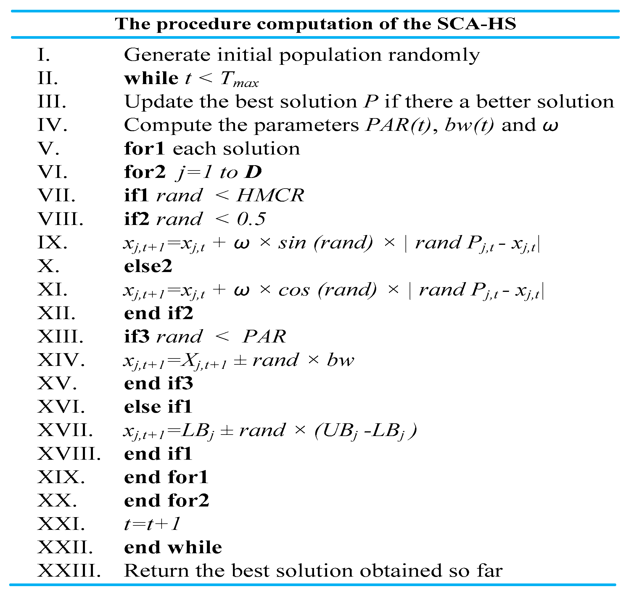
5. Overview of the Original SCA

The Sine Cosine algorithm (SCA) is a recently introduced stochastic heuristic scheme, which is developed based on the mathematical sine and cosine functions [33,34]. The SCA starts with initial candidate solutions and improves them through fluctuating outwards and toward the targeted global solution, using sine and cosine functions as follows:
x j ,   t + 1 = { x j ,   t + ω × sin ( r a n d ) × | r a n d   P j ,   t x j ,   t |       r a n d < 0.5 x j ,   t + ω × cos ( r a n d ) × | r a n d   P j ,   t x j ,   t |       r a n d 0.5
ω = a t a T m a x
where x j ,   t is the current solution at t th iteration in j th dimension, P j ,   t is the best solution, ω is a control parameter which decreases linearly from a constant value a to 0 by each iteration, and Tmax is the total number of iteration.

The Hybrid SCA and HS

In spite the fact that the SCA has exhibited an efficient accuracy more often than other well-known heuristic methodologies, the native algorithm is not fitting for highly complex problems because of its poor exploration capability. To ameliorate the diversification of the standard SCA, the improvisation strategy used in HS is integrated into the SCA. In this way, a component of each search agent X = ( x 1 , x 2 , , x D ) is generated by using the SCA mechanism, with a probability of the harmony memory consideration rate ( H M C R ). While with the rate of ( 1 H M C R ), a new component is randomly generated within the range of [ L B U P ], where LB and UP are the lower and upper bounds of the search agent space. Moreover, with a probability of HMCR multiplying the pitch adjustment rate ( P A R ), the surrounding space of a search agent is searched by the coefficient distance bandwidth ( b w ). To guarantee a quick convergence and to guarantee the quality of the search agents, the design coefficients of the SCA-HS algorithm ( P A R ,   b w ) are dynamically updated during the evaluation procedure [35], given as:
P A R t = P A R m i n + ( P A R m a x P A R m i n ) × t / T m a x
b w t = b w m a x e ( ln ( b w m i n b w m a x ) T m a x × t )
where P A R m i n and P A R m a x are the minimum and maximum pitch adjustment, respectively. Likewise, b w m i n and b w m a x are the minimum and maximum bandwidths, respectively.
The computational procedure of combination of the SCA with HS is depicted in Figure 4.
The evolutionary algorithms (e.g., genetic, firefly, cuckoo search, etc.) merely require information about the objective function. For online setting of the controller coefficients, a proper objective function should be defined for the guidance of its search of heuristic methodologies. In this study, the objective function of Equation (30) is adopted to adjust optimally the coefficients embedded in the FOSMC controller optimally.
J = 0 t .   e s e t p o i n t 2 ( t ) + Δ u 2 ( t ) . d t
where eset-point is the error signal and Δ u is the control signal.

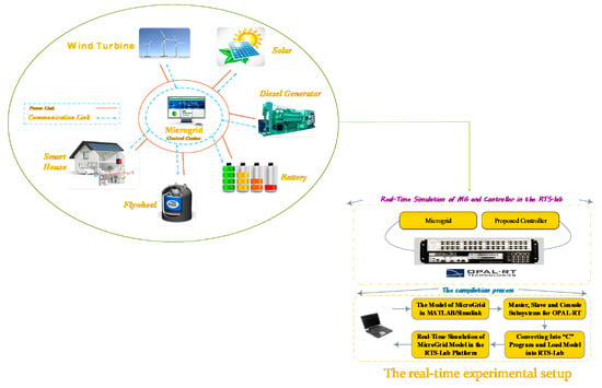
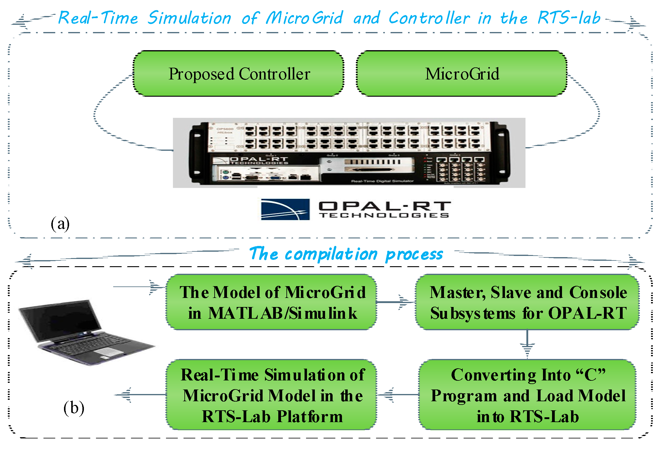
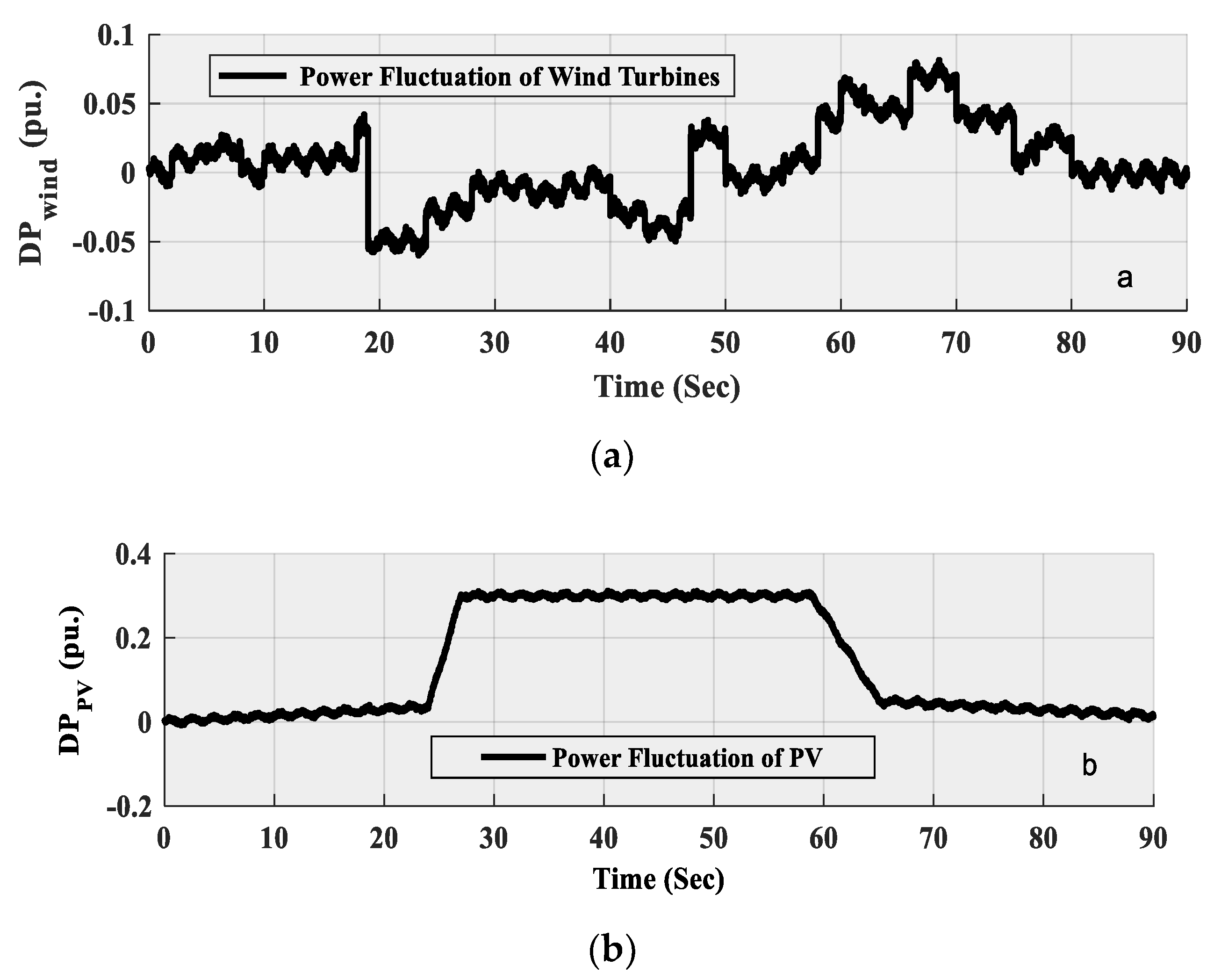
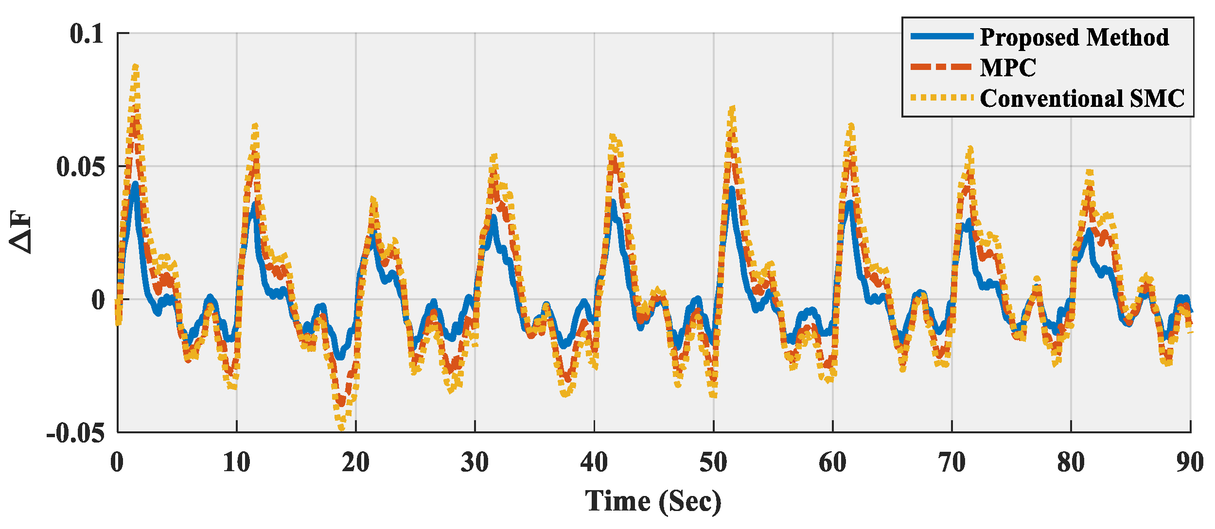
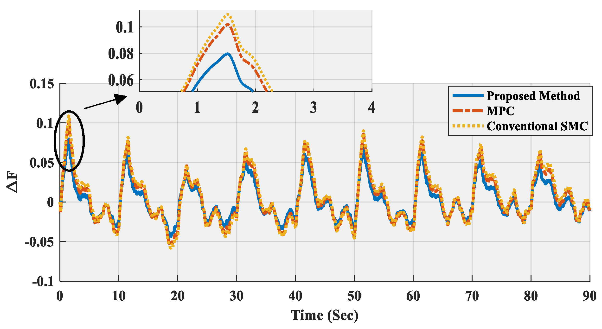
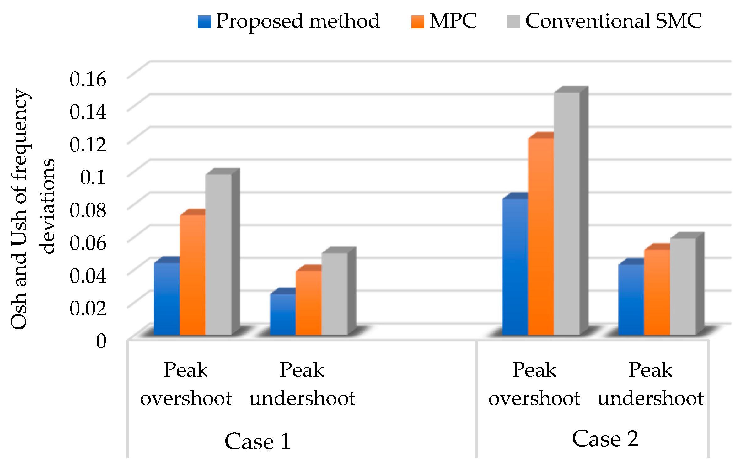
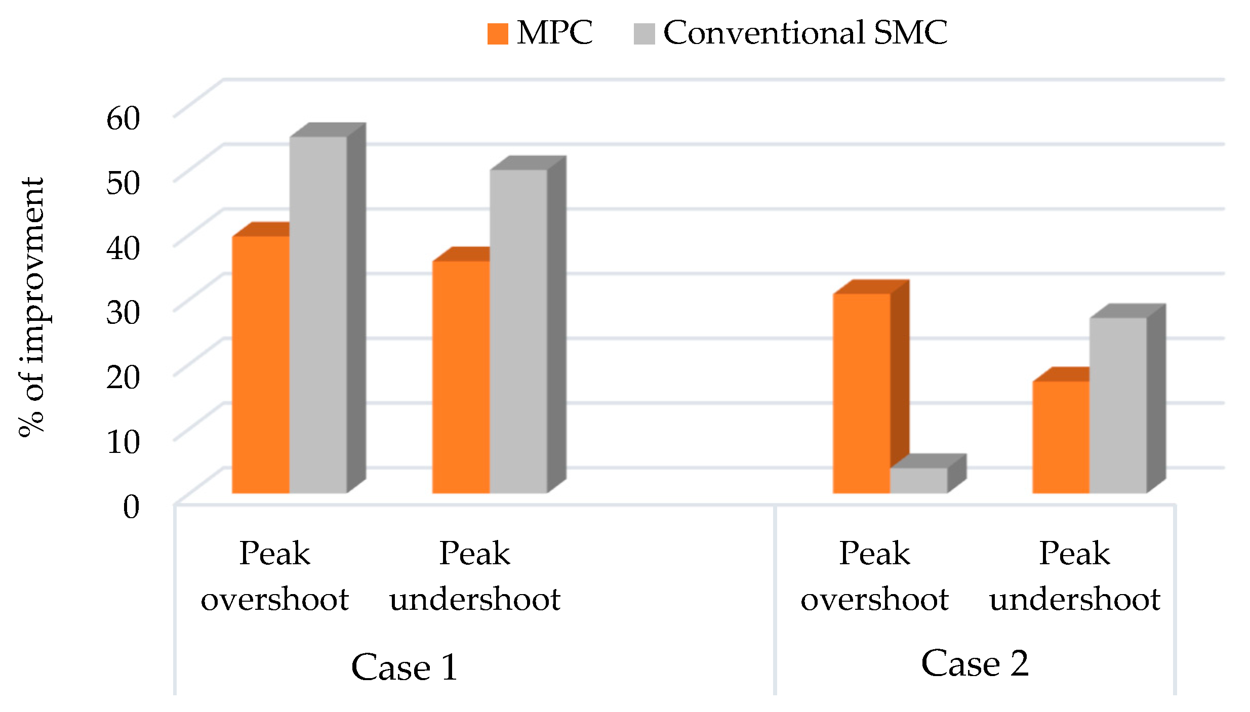
6. Simulation and Real-Time Results

In this section, the MG, which is provided in Figure 3, is simulated in MATLAB/Simulink (R2017a, MathWorks, MA, USA, 2017) to investigate the efficiency of the FOSMC method from a systematic perspective. To confirm the applicability of the FOSMC in the context of MGs, the experimental examinations are conducted. The FOSMC-based experimental outcomes of the test MG are compared to the well-known methodologies, such as MPC and SMC. In this application, the real-time HIL testbed is established to take into account the delays and realistic errors that are not considered in the usual off-line simulation. The schematic diagram of the HIL setup is depicted in Figure 5 and the main parts of the setup are given below [34,36].
(i)
A real-time OPAL-RT simulator is used which simulates the studied MG shown in Figure 3;
(ii)
For the programming host, a PC is used as the command station to execute the MATLAB/Simulink based-code on the OPAL-RT;
(iii)
A router is established to connect all the setup devices in the same sub-network. In this application, the OPAL-RT is connected to the DK60 board by Ethernet ports.
Case 1:
In this case, it is supposed that the load demand of the isolated MG is unvarying, i.e., Δ P L = 0 . On the other hand, the power randomness of the WTG ( Δ P w ) and PVG ( Δ P p v ) are involved in the LFC-based MG. The profile of the wind power fluctuation, which is extracted from an offshore wind farm in Sweden [37], is depicted in Figure 6a, while Figure 6b illustrates the solar radiation data in Aberdeen [38], which was used in this test MG. By employing the real data, the frequency outcomes of the MG system in the HIL environment are depicted in Figure 7.
According to Figure 7, the desired level of the MG outcome ( Δ f ), regarding settling time and transient fluctuations, is provided by the FOSMC controller. In comparison, the suggested technique can achieve much smaller fluctuations of Δ f with quicker outcome specifications than the MPC and SMC approaches. In other words, the real-time outcomes confirm that the suggested technique can handle the randomness of the WTG and PV more effectively as compared to the considered model-based approaches.
Case 2:
In this case, to confirm the robustness of the FOSMC controller, some parameters of the MG (i.e., R , D , H , T i n v , and T g ) are changed. The percentage of the variations for the test system is furnished in Table 2.
As observed in Table 2, a sever scenario of changing the MG parameters is considered to assure the robustness of the suggested FOSMC scheme. The real-time results obtained by the suggested controller, MPC, and conventional SMC are depicted in Figure 8.
The results of Figure 8 reveal that when the system parameters are changed, both the MPC and conventional SMC can still provide robust LFC performance, but they are not adequately optimal. Moreover, the results indicate that the proposed controller provides a higher degree of robustness in comparison with the other two control strategies.

7. Discussion

The stochastic feature of the renewable energy items, i.e., wind and solar energies, introduces oscillations in the MG frequency. Under such circumstances, LFC plays a great role in the MG system because of its duty to preserve frequency in its scheduled value, in normal conditions, and in case of a very slight deviation of the load. However, the control of the hybrid power system operations in uncertain environments is a more complex task, without using a sufficient analytical model. This makes it necessary to apply advanced control methodologies for the realization of the system stability requirements.
Having knowledge of all the aforesaid, a new model-based FOSMC controller is developed to ameliorate the LFC performance of an MG with high penetration of RESs. To ascertain the superiority of the suggested model-based controller, two scenarios (Case 1 and Case 2) corresponding to the fluctuation of RESs and their severe parametric variations (robustness analysis) are applied. From the experimental results of Case 1 and Case 2, it is reflected that in spite of having the high system complexity with the fluctuation nature of the RESs, all the designed LFC controllers can stabilize the grid frequency effectively. In comparison, the FOSMC outperforms the MPC and conventional SMC in terms of the settling time and overshoot. The peak overshoot and undershoot of frequency deviation, using the different controllers, for the two concerned scenarios are compared, as illustrated in Figure 9. Besides, the percentage of improvement of the suggested model-based controller over the MPC and conventional SMC is depicted in Figure 10. The bar graphs of Figure 9 and Figure 10 prove the dominance of the FOSMC controller over both of the other controllers. By comparing the results of Case 1 and Case 2, it is shown that the performance of the designed LFC controllers is deteriorated when the parametric variation is applied to the test MG. However, a higher level of stability is achieved by the proposed method than the other compared controllers.

8. Conclusions

This work investigates a hybrid microgrid, in which the DGs and RESs are integrated to construct a complex plant with advanced functionality. A novel model-based FOSMC technique is designed for the LFC of the concerned MG with high penetration of renewable systems. Since the effectiveness of the model-based technique depends on the controller’s coefficients, a hybrid SCA-HS algorithm is suggested and implemented to tune the coefficients optimally. In the sense of the Lyapunov criterion, the theoretical analysis is conducted to guarantee the stability of the suggested LFC-based MG. Furthermore, hardware-in-the-loop experiments have been carried out in this study to justify the feasibility of the FOSMC controller in a real-time environment. To show the supremacy of the suggested technique, the dynamic behavior of the test MG with the FOSMC controller is compared with the MPC and SMC approaches. Experimental outcomes confirm that the suggested technique successfully handles the aforementioned challenges of the MG, and outperforms the considered techniques.

Author Contributions

Z.E. and M.R conceived and designed the controllers; M.G wrote the paper and analyzed the data; T.D. contributed materials/analysis tools; M.-H.K. performed the experiments.

Funding

This research received no external funding.

Conflicts of Interest

The authors declare no conflict of interest.

Abbreviations

MGMicrogrid
LFCLoad Frequency Control
SMCSliding Mode Control
MPCModel Predictive Control
SCASine Cosine Algorithm
HSHarmony Search
HMCRHarmony Memory Consideration Rate
PARPitch Adjustment Rate
RESRenewable Energy Source
DGDistributed Generator
DEGDiesel Engine Generator
RESRenewable Energy Source
PVPhotovoltaic
WTGWind Turbine Generator
ESSEnergy Storage System
FCFuel Cell
FESSFlywheel Energy Storage System
BESSBattery Energy Storage System
PHEVPlug-In Hybrid Electric Vehicle
MGDSMicrogrid Dispatch System
DMSDistribution Management System
HILHardware-in-the-Loop

References

  1. Chowdhury, S.; Chowdhury, S.P.; Crossley, P. Microgrids and Active Distribution Networks; Institution of Engineering and Technology: London, UK, 2009. [Google Scholar]
  2. Gheisarnejad, M.; Khooban, M.H.; Dragicevic, T. The Future 5G Network Based Secondary Load Frequency Control in Maritime Microgrids. IEEE J. Emerg. Sel. Top. Power Electron. 2019. [Google Scholar] [CrossRef]
  3. Gheisarnejad, M.; Khooban, M.H. Secondary load frequency control for multi-microgrids: HiL real-time simulation. Soft Comput. 2019, 23, 5785–5798. [Google Scholar] [CrossRef]
  4. Bajpai, P.; Dash, V. Hybrid renewable energy systems for power generation in stand-alone applications: A review. Renew. Sustain. Energy Rev. 2012, 16, 2926–2939. [Google Scholar] [CrossRef]
  5. Torreglosa, J.P.; García, P.; Fernández, L.M.; Jurado, F. Energy dispatching based on predictive controller of an off-grid wind turbine/photovoltaic/hydrogen/battery hybrid system. Renew. Energy 2015, 74, 326–336. [Google Scholar] [CrossRef]
  6. Serban, I.; Teodorescu, R.; Marinescu, C. Energy storage systems impact on the short-term frequency stability of distributed autonomous microgrids, an analysis using aggregate models. IET Renew. Power Gener. 2013, 7, 531–539. [Google Scholar] [CrossRef]
  7. Bevrani, H.; Feizi, M.R.; Ataee, S. Robust Frequency Control in an Islanded Microgrid: H and μ -Synthesis Approaches. IEEE Trans. Smart Grid 2015, 7, 706–717. [Google Scholar] [CrossRef]
  8. Khalghani, M.R.; Khooban, M.H.; Mahboubi-Moghaddam, E.; Vafamand, N.; Goodarzi, M. A self-tuning load frequency control strategy for microgrids: Human brain emotional learning. Int. J. Electr. Power Energy Syst. 2016, 75, 311–319. [Google Scholar] [CrossRef]
  9. Jiayi, H.; Chuanwen, J.; Rong, X. A review on distributed energy resources and MicroGrid. Renew. Sustain. Energy Rev. 2008, 12, 2472–2483. [Google Scholar] [CrossRef]
  10. Gheisarnejad, M.; Moghadam, M.; Boudjadar, J.; Khooban, M.H. Active Power Sharing and Frequency Recovery Control in an Islanded Microgrid with Nonlinear load and Non-Dispatchable DG. IEEE Syst. J. 2019, 5, 1–11. [Google Scholar] [CrossRef]
  11. Heydari, R.; Gheisarnejad, M.; Khooban, M.H.; Dragicevic, T.; Blaabjerg, F. Robust and fast voltage-source-converter (vsc) control for naval shipboard microgrids. IEEE Trans. Power Electron. 2019, 34, 8299–8303. [Google Scholar] [CrossRef]
  12. Pan, I.; Das, S. Kriging Based Surrogate Modeling for Fractional Order Control of Microgrids. IEEE Trans. Smart Grid 2015, 6, 36–44. [Google Scholar] [CrossRef]
  13. Pan, I.; Das, S. Fractional order fuzzy control of hybrid power system with renewable generation using chaotic PSO. ISA Trans. 2016, 62, 19–29. [Google Scholar] [CrossRef]
  14. Khooban, M.H.; Niknam, T.; Shasadeghi, M.; Dragicevic, T.; Blaabjerg, F. Load frequency control in microgrids based on a stochastic noninteger controller. IEEE Trans. Sustain. Energy 2017, 9, 853–861. [Google Scholar] [CrossRef]
  15. Pan, I.; Das, S. Fractional order AGC for distributed energy resources using robust optimization. IEEE Trans. Smart Grid 2015, 7, 2175–2186. [Google Scholar] [CrossRef]
  16. Pahasa, J.; Ngamroo, I. Coordinated control of wind turbine blade pitch angle and PHEVs using MPCs for load frequency control of microgrid. IEEE Syst. J. 2014, 10, 97–105. [Google Scholar] [CrossRef]
  17. Pandey, S.K.; Mohanty, S.R.; Kishor, N.; Catalão, J.P.S. Frequency regulation in hybrid power systems using particle swarm optimization and linear matrix inequalities based robust controller design. Int. J. Electr. Power Energy Syst. 2014, 63, 887–900. [Google Scholar] [CrossRef]
  18. Bevrani, H.; Habibi, F.; Babahajyani, P.; Watanabe, M.; Mitani, Y. Intelligent frequency control in an AC microgrid: Online PSO-based fuzzy tuning approach. IEEE Trans. Smart Grid 2012, 3, 1935–1944. [Google Scholar] [CrossRef]
  19. Ghafouri, A.; Milimonfared, J.; Gharehpetian, G.B. Fuzzy-adaptive frequency control of power system including microgrids, wind farms, and conventional power plants. IEEE Syst. J. 2014, 12, 2772–2781. [Google Scholar] [CrossRef]
  20. Qu, Q.; Zhang, H.; Yu, R.; Liu, Y. Neural network-based H∞ sliding mode control for nonlinear systems with actuator faults and unmatched disturbances. Neurocomputing 2018, 275, 2009–2018. [Google Scholar] [CrossRef]
  21. Ngo, Q.H.; Nguyen, N.P.; Nguyen, C.N.; Tran, T.H.; Ha, Q.P. Fuzzy sliding mode control of an offshore container crane. Ocean Eng. 2017, 140, 125–134. [Google Scholar] [CrossRef] [Green Version]
  22. Ma, X.; Sun, F.; Li, H.; He, B. Neural-network-based sliding-mode control for multiple rigid-body attitude tracking with inertial information completely unknown. Inf. Sci. 2017, 400, 91–104. [Google Scholar] [CrossRef]
  23. Gheisarnejad, M.; Khooban, M.H. Design an optimal fuzzy fractional proportional integral derivative controller with derivative filter for load frequency control in power systems. Trans. Inst. Meas. Control. 2019, 41, 2563–2581. [Google Scholar] [CrossRef]
  24. Khooban, M.H.; Gheisarnejad, M.; Vafamand, N.; Boudjadar, J. Electric Vehicle Power Propulsion System Control Based on Time-Varying Fractional Calculus: Implementation and Experimental Results. IEEE Trans. Intell. Veh. 2019, 4, 255–264. [Google Scholar] [CrossRef]
  25. Xiong, L.; Wang, J.; Mi, X.; Khan, M.W. Fractional order sliding mode based direct power control of grid-connected DFIG. IEEE Trans. Power Syst. 2017, 33, 3087–3096. [Google Scholar] [CrossRef]
  26. Dadras, S.; Momeni, H.R. Fractional terminal sliding mode control design for a class of dynamical systems with uncertainty. Commun. Nonlinear Sci. Numer. Simul. 2012, 17, 367–377. [Google Scholar] [CrossRef]
  27. Podlubny, I. Fractional Differential Equations: An Introduction to Fractional Derivatives, Fractional Differential Equations, to Methods of Their Solution and Some of Their Applications; Elsevier Science: Amsterdam, The Netherlands, 1998. [Google Scholar]
  28. Li, C.; Deng, W. Remarks on fractional derivatives. Appl. Math. Comput. 2007, 187, 777–784. [Google Scholar] [CrossRef]
  29. Li, Y.; Chen, Y.Q.; Podlubny, I. Stability of fractional-order nonlinear dynamic systems: Lyapunov direct method and generalized Mittag–Leffler stability. Comput. Math. Appl. 2010, 59, 1810–1821. [Google Scholar] [CrossRef]
  30. Wang, B.; Ding, J.; Wu, F.; Zhu, D. Robust finite-time control of fractional-order nonlinear systems via frequency distributed model. Nonlinear Dyn. 2016, 85, 2133–2142. [Google Scholar] [CrossRef]
  31. Khooban, M.-H.; Niknam, T.; Blaabjerg, F.; Davari, P.; Dragicevic, T. A robust adaptive load frequency control for micro-grids. ISA Trans. 2016, 65, 220–229. [Google Scholar] [CrossRef]
  32. Khooban, M.H.; Niknam, T.; Blaabjerg, F.; Dragičević, T. A new load frequency control strategy for micro-grids with considering electrical vehicles. Electr. Power Syst. Res. 2017, 143, 585–598. [Google Scholar] [CrossRef] [Green Version]
  33. Mirjalili, S. SCA: A Sine Cosine Algorithm for solving optimization problems. Knowl. Based Syst. 2016, 96, 120–133. [Google Scholar] [CrossRef]
  34. Khooban, M.H.; Gheisarnejad, M.; Vafamand, N.; Jafari, M.; Mobayen, S.; Dragicevic, T. Robust Frequency Regulation in Mobile Microgrids: HIL Implementation. IEEE Syst. J. 2019. [Google Scholar] [CrossRef]
  35. Xiang, W.L.; An, M.Q.; Li, Y.Z.; He, R.C.; Zhang, J.F. An improved global-best harmony search algorithm for faster optimization. Expert Syst. Appl. 2014, 41, 5788–5803. [Google Scholar] [CrossRef]
  36. Khooban, M.H.; Dragicevic, T.; Blaabjerg, F.; Delimar, M. Shipboard microgrids: A novel approach to load frequency control. IEEE Trans. Sustain. Energy 2017, 9, 843–852. [Google Scholar] [CrossRef]
  37. Database of Wind Characteristics. Available online: www.winddata.com (accessed on 10 October 2014).
  38. Solar Radiation Modeling. Available online: www.solargis.info/doc/solar-and-pv-data (accessed on 10 October 2014).
Figure 1. A general configuration of microgrids.
Applsci 09 03411 g001
Figure 2. Model of the diesel engine generator (DEG) system.
Applsci 09 03411 g002
Figure 3. The overall microgrid (MG) scheme for load frequency control (LFC). FOSMC: fractional order sliding mode control.
Applsci 09 03411 g003
Figure 4. The pseudo-code of the proposed optimization algorithm.
Applsci 09 03411 g004
Figure 5. The real-time experimental setup; (a) the real-time simulation of MG and controller in the real-time simulator laboratory (RTS-LB) (b) the compilation process.
Applsci 09 03411 g005
Figure 6. Power fluctuation, (a) wind power generator (WPG), (b) photovoltaic (PV).
Applsci 09 03411 g006
Figure 7. Curves of the MG response with the application of WPG and PV.
Applsci 09 03411 g007
Figure 8. Curves of the MG response according to Case 2.
Applsci 09 03411 g008
Figure 9. Peak overshoot and undershoot of frequency deviation using various control strategies.
Applsci 09 03411 g009
Figure 10. Percentage of improvement of the suggested technique over the MPC and conventional SMC controllers.
Applsci 09 03411 g010
Table 1. The MG power system’s parameters.
Symbol and AbbreviationValuesSymbol and AbbreviationValues
Δ P L (change in load power)0.02 s T g (governor time constant)0.08 s
T i n v (time constant of inverter circuit of solar unit)0.04 s T b (battery power time constant)0.1 s
T f c (time constant of fuel cell)0.26 s2H (inertia constant)0.1667
T f i l t (time constant of filter circuit of solar unit)0.004 sD (damping coefficient)0.015
T t (diesel generator time constant)2.00 sR (DG speed regulation)3
Table 2. Uncertain parameters of the test MG.
ParametersVariation Range
R 20 %
D + 35 %
H 10 %
T i n v 25 %
T g + 25 %

