1. Introduction
Reducing machining errors is a common goal for the machining industry. For a three-axis machine tool, there are 21 different geometric errors, including the linear positioning errors for each axis and the angular errors for each axis as well as between two axes [
1]. The linear positioning errors are usually caused by the backlash of the ball screws used for the linear axes. The errors can be minimized by calibration with the use of laser interferometry. In addition to the geometric errors, the dynamic errors generated during the machining process also affect the accuracy of machining. The errors are usually caused by the variable cutting forces, machine vibrations, and the uncertain wear of the cutting tools [
2]. Generally, the computer numerical control (CNC) controllers of a machine tool cannot cope with these errors. The heat generated during machining can also affect the machining accuracy [
3].
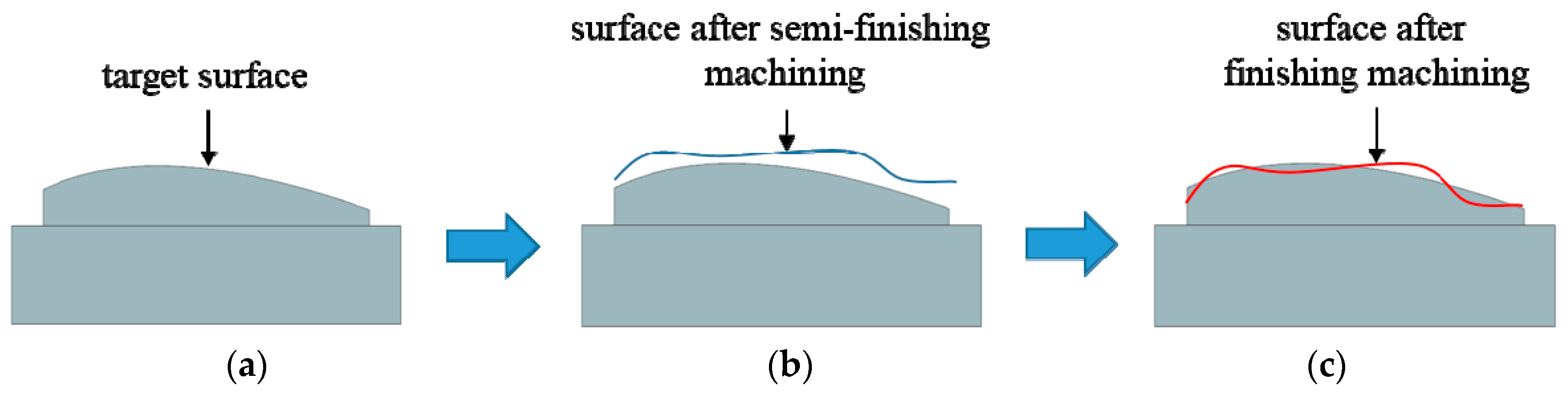
In today’s industry, the inaccuracy of the free-form surfaces of a machined workpiece can be improved by the following procedure: Perform roughing machining and semi-finishing machining first. For the semi-finishing machining, the excess material, or the stock, will be increased so that there is enough material left for the finishing machining. The average error can be obtained through the measurement, which can be on-machine or off-machine, after the semi-finishing machining. Based on the error, we can modify the tool radius in the computer-aided manufacturing (CAM) software and then regenerate the tool paths for finishing machining. By compensating for the error by modifying the tool radius, the tool paths can only be shifted inward or outward by a constant value, and it is not possible to improve the accuracy at a specific location only, as illustrated in
Figure 1. As shown in
Figure 1b, the profile of the workpiece after semi-finishing machining is different from the target shape shown in
Figure 1a. Even if we perform the compensation by tool radius modification as described above, the average geometry may be close to the target geometry, as shown in
Figure 1c. However, the local variation cannot be improved.
Off-machine and on-machine measurement have advantages and disadvantages. To use off-machine measurement, it is not necessary to consider the measurement error caused by the machine tool itself; however, because the workpiece needs to be unmounted, there will be re-clamping errors. On the other hand, using on-machine measurement needs to rely on the repeatability of the machine tool, but it will not cause re-clamping errors, and can also reduce the time and efforts for re-clamping. At present, the precision of the machine tool is increasing, and the difference between the on-machine and the off-machine measurement is getting smaller. Therefore, dealing with the use of on-machine measurement results for error compensation has become an increasingly important issue.
Many error compensation methods have been proposed for free-form surfaces. Poniatowska [
4] proposed a method to compensate for systematic errors on the machined surface. A machining pattern model (MPM), which represents the average of several surfaces machined under repeatable conditions, was used as the compensation basis. Regression analysis and spatial statistical methods were used to remove the random effects. The model was then used for reconstructing the computer aided design (CAD) model of the surface. The new cutting tool path can be generated to remove systematic errors. Chen et al. [
5] used the spatial independence analysis method to decompose the machining errors measured online into systematic errors and random errors. For systematic errors, the numerical control (NC) codes can be modified for error compensation. Lai et al. [
6] used the T-spline surface with local refinement instead of the common non-uniform rational B-splines (NURBS) surface to obtain better accuracy. The points used for the T-spline surface were obtained by using the on-machine measurement, and then the mirror symmetry model was adopted to construct the compensation surface. Cho et al. [
7] performed machining surface error compensation through an on-machine measurement system. They performed multiple machining to obtain the error distribution. Based on the relationship between cutting conditions and surface error, an attempt was made to correct the tool path in order to reduce the errors using an iterative algorithm. Lasemi et al. [
8] classified the errors in the machining of free-form surfaces as machine-related errors and process-related errors. The machine-related errors can be compensated offline, and the process-related errors can only be compensated online by re-planning the tool paths. Gu et al. [
9] developed the global offset method to compensate for the machining errors of a five-axis machine tool. The method was based on the off-machine measurement of machined parts by using a coordinate measuring machine (CMM), and a compensation processor was used to calculate the parameters for the controller of the machine tool to perform compensation. Chen et al. [
10] decomposed the machining errors into systematic errors and random errors by using the empirical mode decomposition method, and the systematic errors can then be compensated by using the offline measurement data. Huang et al. [
11] developed an iterative compensation algorithm to modify the NC code based on the geometric errors, so that the real tool path generated by the compensated NC code and the designed tool path were within the tolerance. Zhong et al. [
12] established the error of kinematics synthesis model and used the model to compensate the
x-axis and
z-axis positioning errors of a four-axis polishing machine. Msaddek et al. [
13] presented a method of compensation by the insertion of the nodes to reduce the errors caused by the Bspline and Cspline interpolations on the machining surface. Chen [
14] used an artificial neural network to predict the thermal error and used a PC-based controller to send the compensation information to the CNC controller to perform real-time error compensation.
Because the on-machine measurement depends on the precision of the machine tool, the source of the error on the machine tool is also critical. Biral et al. [
15] used the online servo-controlled inclinometers to measure the geometric errors of the motion axes. That information was used by the CNC controller to compensate for the positioning errors. Guiassa et al. [
16] used on-line measurement data for achieving compensation. Dimensional compensation can be achieved by correcting the tool size and the tool path. They proposed a method based on the cutting depth distribution to correct the tool offset error.
Regarding manufacturing the free-form surfaces, some novel methods have been proposed. Bo et al. [
17] proposed an algorithm to find patches on free-form surfaces that can be machined by the flank of a conical cutting tool, and they extended their work to find the initial path for five-axis flank CNC machining with a general cutting tool [
18]. Calleja et al. [
19] also developed an algorithm to generate the flank milling paths for free-form surface machining with the use of a tapered mill tool. Using the flank of a cutting tool can increase the efficiency of manufacturing the free-form surfaces. Because gear surfaces may be treated as free-form surfaces, we can also find the information related to making free-form surface from gear manufacturing. Álvarez et al. [
20] presented machining strategies and parameters used in different stages for milling the gear surfaces of spiral bevel gears by using NX CAD/CAM software.
From the previous research, we can learn that researchers have performed much compensation research based on the on-machine and off-machine measurement of free-form surfaces. However, determining how to reduce the time needed to generate the tool path for compensation and increase the accuracy are still in demand. In the past, the research often relied on CAIP (Computer-Aided Inspection Planning) software, but it was impossible to integrate machining, measurement, and compensation into the same software system, which would cause unnecessary difficulty for process automation. Therefore, the objective of this research was to integrate the machining, measurement, and compensation into the same CAD/CAM software to correct the machining error of free-form surfaces. It was concluded that the generation of the tool path for compensation could be very efficient, and the standard deviation of the machined free-form surfaces can be reduced by at least 32% using the mirror compensation method proposed in this paper.
2. Materials and Methods
2.1. Equipment and Software
The machine used in this research is a five-axis CNC vertical milling machine tool (model No. UX300) made by Quaser (Taiwan). The machine is table–table type, and its controller is SIEMENS 840D, which is connected to the Intranet in our institution. The on-machine measurement probe is the one with model number OMP400 made by RENISHAW (UK). The diameter of the stylus is 6 mm, and the length is 50 mm. The repeatability of the probe is 0.25 μm for two standard deviations.
The CAD/CAM system used in this study was NX (SIEMENS, Munich, Germany), and the program we developed for this research was written in Visual Studio C# (Microsoft, Redmond, WA, USA). We used the NX Open API to link NX with our program. As long as the measurement tool path is determined in NX, then the post-processor in NX can be used to output an NC file containing RENISHAW macro commands for probing. The NC file can then be combined with the NC file for manufacturing in the SIEMENS controller so that the on-machine measurement can be performed after the material cutting. After the on-machine measurement is completed, the measured data are stored in the controller, and our program can access the data through the Intranet for the subsequent processes.
2.2. Free-Form Surface Design
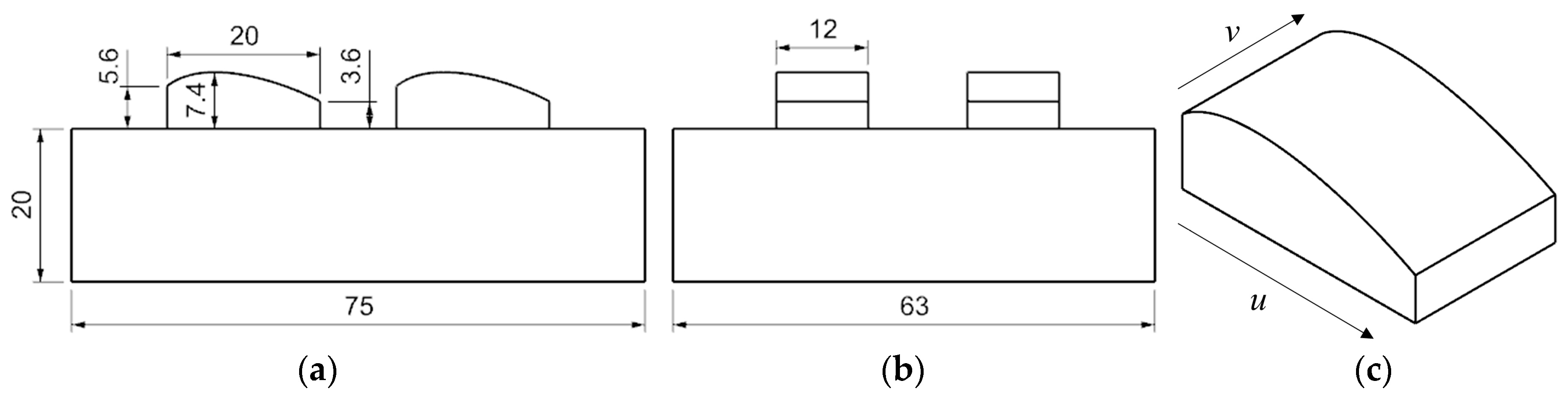
The workpiece material for the experiment was A6061-T6 aluminum alloy, and the size was 75 × 63 × 30 mm. In this study, three different surfaces were adopted for the experiment. For each surface, we machined four replicas so that we could obtain more measurement data. There are three profiles mainly used in the free-form surface design, as shown in
Figure 2,
Figure 3 and
Figure 4, all of which are quadratic curved surfaces. The first surface, Surface one, is shown in
Figure 2. The curves in the
u-direction on the curved surface are identical quadratic curves, and those in the
v-direction are horizontal straight lines.
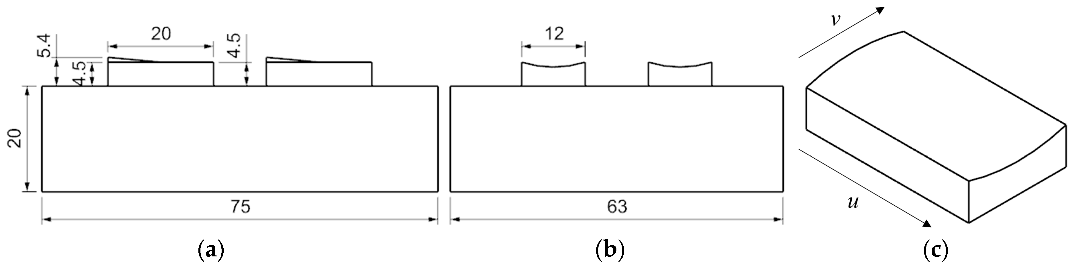
The second surface, Surface two, is shown in
Figure 3. The curves in the
u-direction on the surface are straight lines with different slopes. The ones in the
v-direction are quadratic curves, which start from a convex quadratic curve from one side and end with a concave curve at the other side.
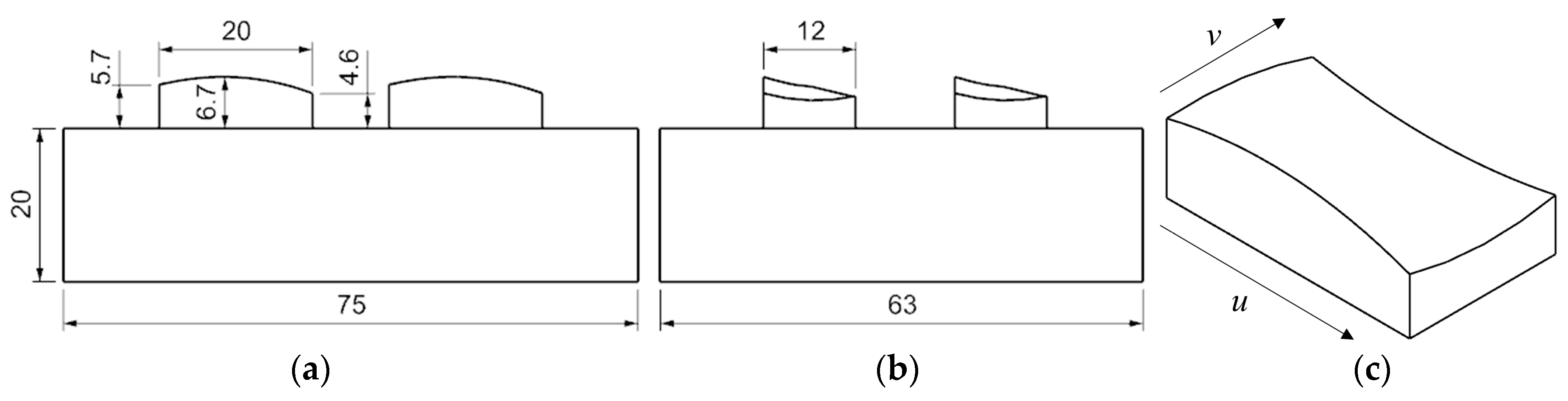
The third surface, Surface three, shown in
Figure 4, is the most complex surface among the three surfaces. The curves in the
u-direction and the
v-direction on the surface are all quadratic curves. They all start from convex quadratic curves from one side, and end with concave curves at the other side.
2.3. Measurement Points and Fitted Free-Form Surfaces
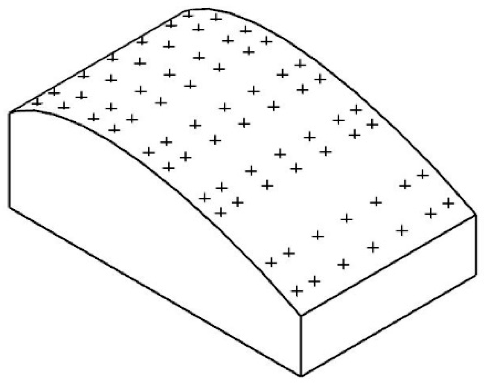
The measurement points for generating the measurement paths were all set on the ideal surface in the original CAD model. The number of measurement points is related to the accuracy of the surface fitting. The locations of the measurement points were determined based on the slopes of the points on the curves along the
u-direction. We added measurement points at locations where the change of the slope of two adjacent measurement points was significant, and removed the measurement points at locations where the change of the slope of two adjacent measurement points was little.
Figure 5 shows the measurement points on Surface one. Seven curves (not shown) in the
u-direction were used, and ten measurement points are distributed along each curve. From this figure, we can see that there were more measurement points on the top-left of the surface because that was the place where the slopes of the points on the curves changed rapidly.
In this study, we used the functions in NX Open API to perform both the curve fitting and the surface fitting. After obtaining the compensation points, we used the points on the same v coordinate to perform curve fitting along the u-direction, and the points on the same u coordinate to perform curve fitting along the v-direction. The two groups of curves were then used for surface fitting. The order of the fitted curve was determined using the criteria that the average of the distances from the compensation points to the fitted curve must be less than a threshold, which was set at 1 μm in the study. It was found that we could use the third-degree curves to achieve this.
NX includes at least five surface fitting methods: Studio Surface, Fit Surface, Through Curves, Through Curve Mesh, and UFun. To evaluate the methods, we designed two experiments: One was to use the five methods with a set of the compensation points for each surface design to fit surfaces, and find the average of the distances,
d1, from the compensation points to the fitted surface. The other was to arbitrarily pick up 1000 points from the surfaces of the reconstructed CAD models, and find the average of the distance,
d2, of these points to the fitted surface used for the reconstruction of the CAD models. The experimental results are listed in
Table 1. It can be seen that the Through Curves Mesh method had the best results for Surface two and Surface three. For Surface one, the Through Curve Mesh performed second to UFun. However, UFun did not perform well for Surface two and Surface three. Therefore, in the subsequent study, we used Through Curve Mesh for surface fitting.
2.4. Concept of Mirror Compensation
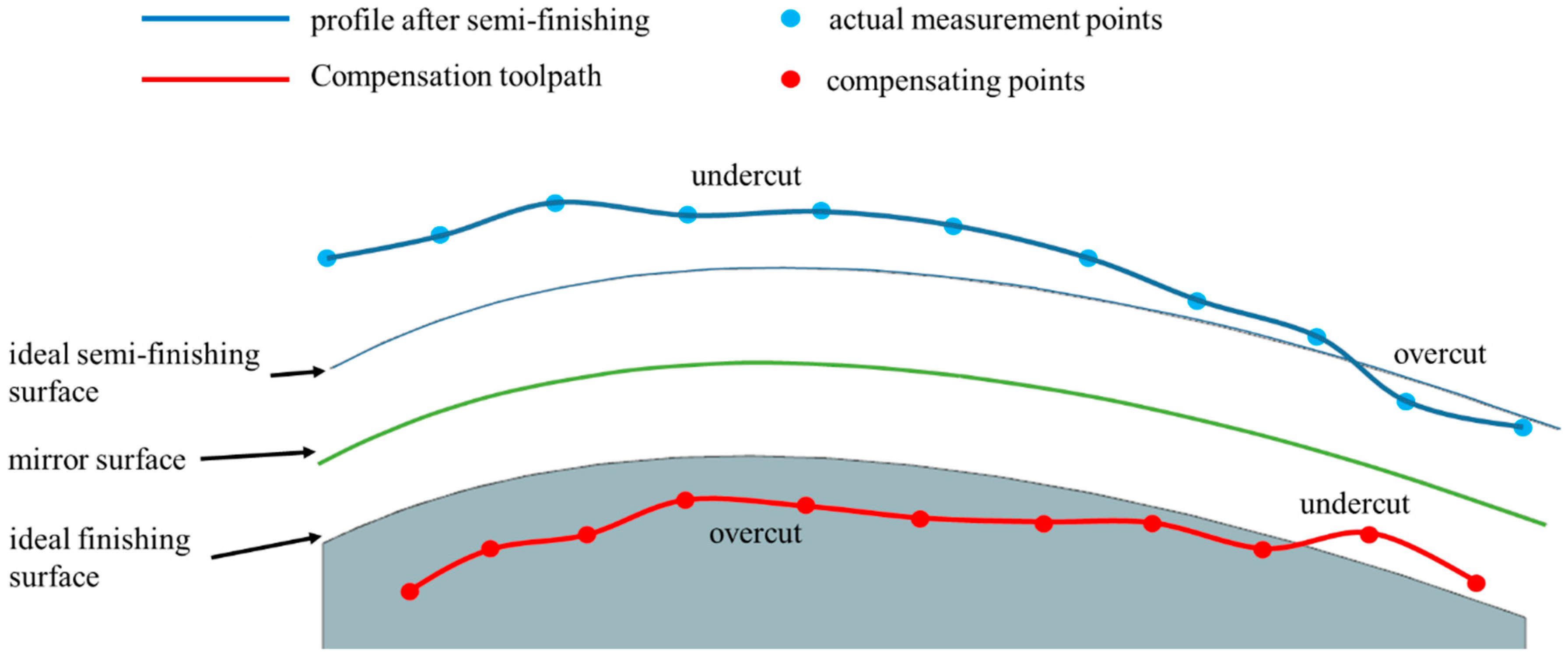
In this study, the mirror compensation method was used to compensate for the errors of free-form surface machining. The compensation method was used after the semi-finishing machining was completed. The on-machine measurement was made on the semi-finishing surfaces to obtain the actual semi-finishing surface. Then, a mirror surface was introduced to mirror the actual semi-finishing surface to obtain the finishing surface for error compensation. The mirror surface is the mid-surface between the ideal semi-finishing surface and the ideal finishing surface, as indicated in
Figure 6. This method finds where there is an undercut and where there is an overcut after semi-finishing machining. As illustrated in
Figure 6, an undercut indicates that the remaining amount of material has exceeded the expected amount of material; an overcut indicates that the remaining amount of material has fallen short of the expected amount of material. Afterward, the semi-finishing surface is mirrored. The undercut locations on the semi-finishing surface will receive overcut during the finishing machining; the overcut locations will receive undercut during the finishing machining. As a result, after finishing machining, the machined surface is expected to approach the expected ideal surface or the target surface.
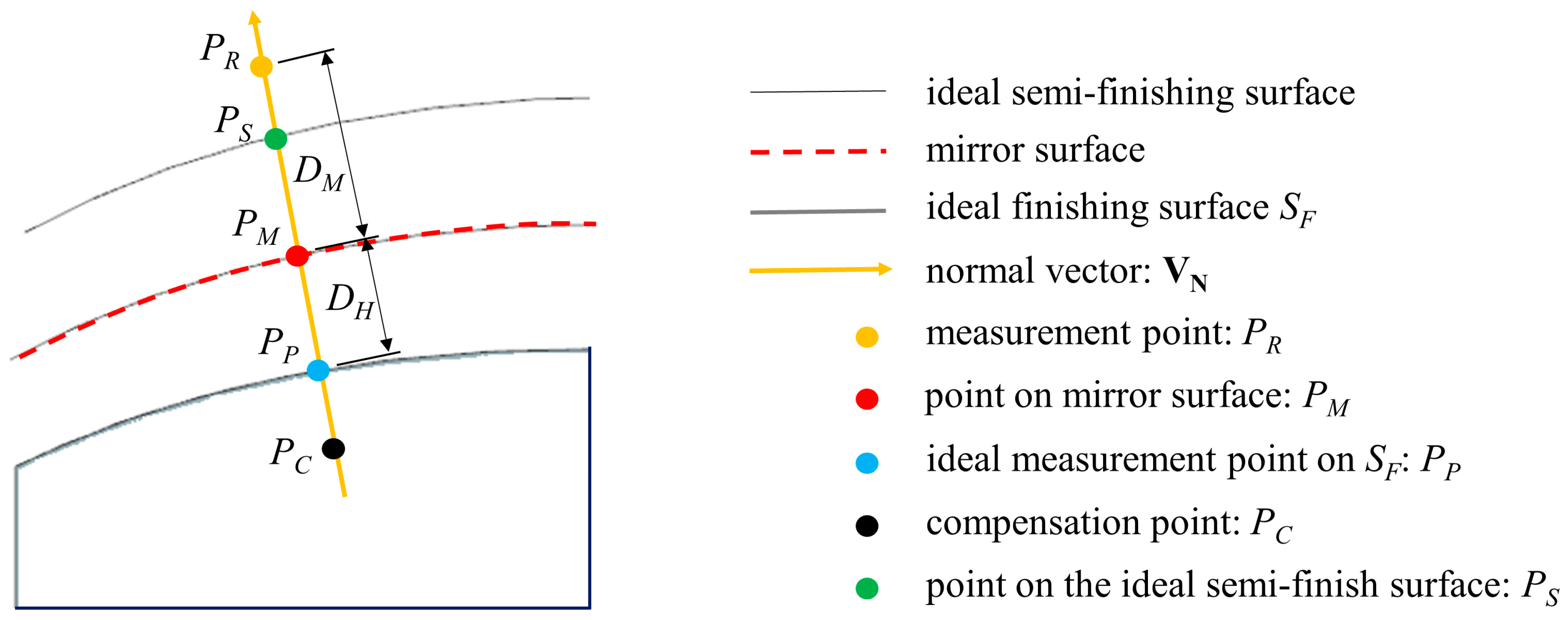
How to use the mirror compensation method to find the compensation points is illustrated in
Figure 7. First, we defined our ideal point
PP on the ideal finishing surface
SF. Then, we could obtain the normal vector
VN at
PP on the ideal finishing surface
SF. As explained previously, the mirror surface is the mid-surface between the ideal semi-finishing surface and the ideal finishing surface. Therefore, the distance
DH, which is half of the stock for the semi-machining, from
PP to the mirror surface is known. Then Equation (1) can be used to find
PM on the mirror surface. As long as
PM is known, the distance
DM from
PM to
PR can be readily obtained, as can the compensation point
PC by using Equation (2).
In the following analysis, the distance between PR to PP was used as the error for semi-finishing machining, and the distance from the actual measurement point after finishing machining to point PP was used as the error for finishing machining.
2.5. Automatic Compensation Implementation
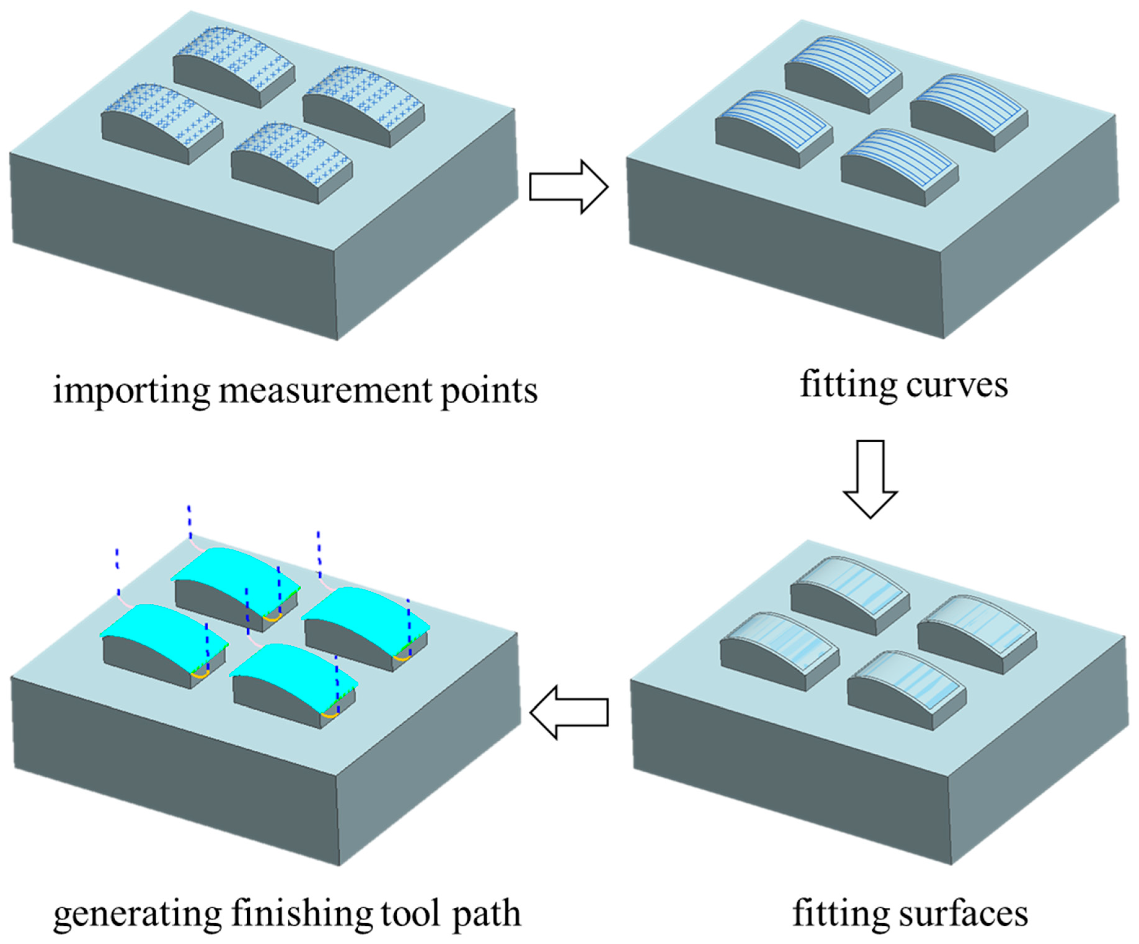
The complete compensation process is shown in
Figure 8. We used the C# program we developed to import the on-machine measurement results. Because we used the same work coordinate system created by G54 command for cutting tool path and the on-machine measurement, the on-machine measurement data can be registered with the CAD model used for generating the G code for machining. Then, the mirror compensation method can be applied to find the locations of the compensation points. It follows that the curve fitting is performed on the compensation points, and the free-form surface can then be constructed by using the Through Curve Mesh fitting function in NX. Finally, the fitted surfaces will replace the original surfaces in the CAD model so that the model is reconstructed for generating the finishing tool path. The program we developed can automatically execute the entire process. For a model like the one shown in
Figure 8, it took only about 30 s to complete the processes on a regular PC. It may take a much longer time to complete the same task by manual operation.
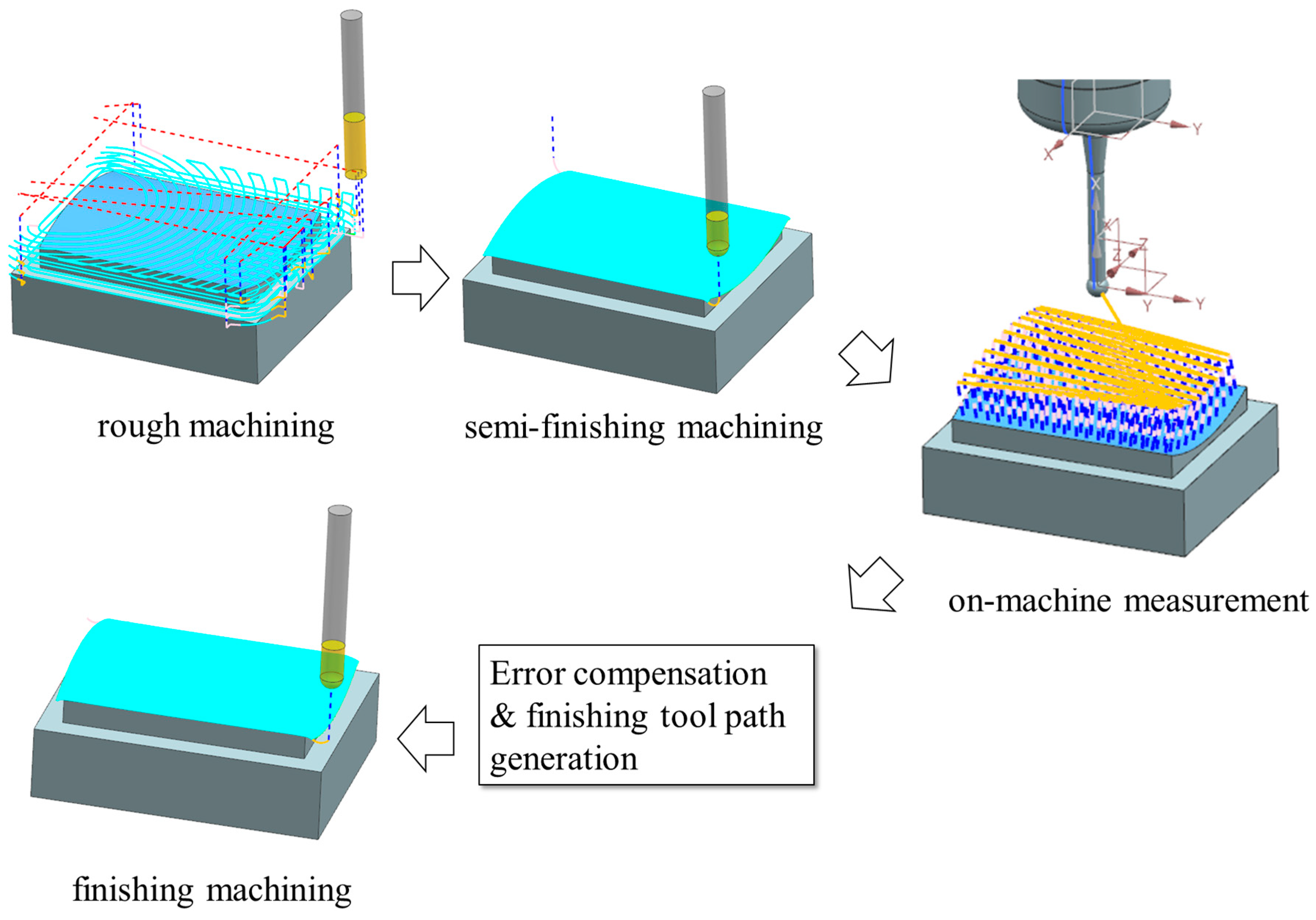
The complete machining process, including error compensation, is shown in
Figure 9. First, the roughing machining and semi-finishing machining are performed. Then the on-machine measurement is performed, and the measurement data are recorded inside the CNC controller. Next, the automatic compensation program is used to perform the procedure, as illustrated in
Figure 8. After obtaining the finishing tool path, we can perform the finishing machining to complete the machining with error compensation.
2.6. CAM Setup and Cutting Conditions
The tool paths for machining the free-form surfaces were generated in NX. The stock for the rough machining, the semi-finishing machining, and the finishing machining was set at 0.4 mm, 0.2 mm, and 0 mm, respectively. For the semi-finishing machining and finishing machining, the streamline operation in NX was adopted for tool path generation. Also, the scallop height was set at 1 μm, and the profile error, which is the chordal error along the linear interpolated tool path, was set at ±1 μm.
The cutting tool used in free-form surface machining for both the semi-finishing and finishing machining was made of tungsten carbide with TB coated. The tool was a two-flute ball end mill, 6 mm in diameter. The cutting conditions were as follows: the spindle speed was 10,000 RPM, the feed rate was 1200 mm/min, the surface cutting speed was 188 m/min, and the corresponding feed rate per blade was 0.06 mm/tooth.
3. Results and Discussion
This section presents the results of the automatic error compensation method proposed in this study. The number of measurement points of each replica for the three surface designs was different. Surfaces one, two, and three had 70, 49, and 68 measurement points for each replica, respectively. We used two different error compensation methods, tool radius modification and the mirror method as discussed previously, to carry out the error compensation and find their results.
Because we machined four replicas for each surface design, as shown in
Figure 2,
Figure 3 and
Figure 4, we would like to examine the repeatability of the four replicas first.
Table 2 shows the standard deviations of the errors of the four replicas for each surface design. The values without the parentheses represent the standard deviations for the replicas before and after error compensation, and the values within the parentheses represent the range (the difference between the lowest and highest values) for the standard deviation of the errors for the four replicas. As listed in
Table 2, most of the ranges are less than 0.5 μm, and the maximum range is 0.8 μm, which comes from the measurement results of Surface three after mirror compensation. Except for this case, all the other results show consistent standard deviations among the four replicas for the three surfaces before and after compensation, regardless which compensation method we used.
Because the repeatability of the four replicas is reasonably good in general, we will show the error distribution of one of the replicas (replica one) before and after error compensation by using either the tool radius compensation method or the mirror compensation method to illustrate the error distribution for all four replicas. The reason we do not show the distribution for all four replicas is that we would like to focus on the comparison between the two compensation methods without using too much space of the paper.
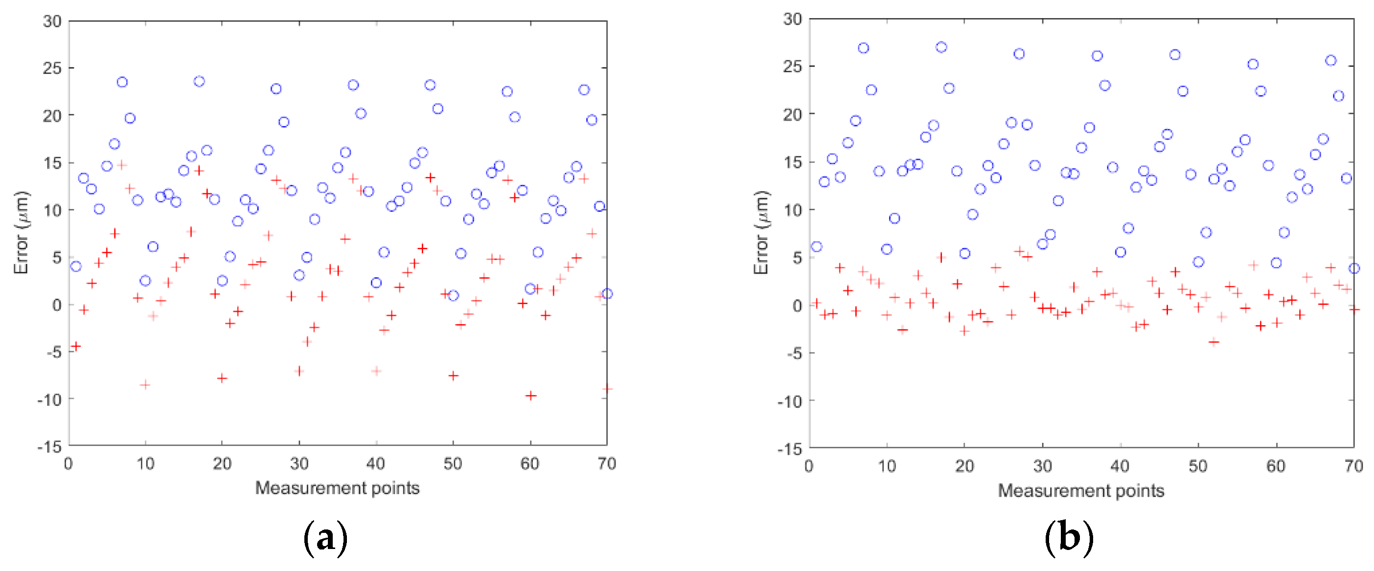
After performing the semi-finishing machining on the four replicas of Surface one, we obtained the error distribution of the free-form surface of replica one, as the circles shown in
Figure 10a. The average error after semi-finishing machining was 12.3 μm with a standard deviation of 6.0 μm. After the tool radius compensation was performed, the error distribution became the plus signs in
Figure 10a. The average error was reduced to 3.1 μm, but the standard deviation became 6.2 μm, which was almost unchanged. It is evident that the average error was much improved, but with no significant improvement in the variation.
On the other hand, we repeated the previous experiment by using the mirror compensation method proposed in this study. The error distribution of replica one before and after the mirror compensation is shown in
Figure 10b. Because the error compensation was already performed on the free-form surfaces used in the previous experiment, we had to machine new surfaces for this experiment. The average error after semi-finishing machining was 15.0 μm with a standard deviation of 6.0 μm. After error compensation was performed, the average error was 0.7 μm, and the standard deviation was 2.0 μm. The average error was improved by 14.3 μm, and the standard deviation was improved by 4.0 μm, which demonstrated that the proposed error compensation method could significantly improve the surface variation. Similar results were obtained for the other three replicas of Surface one.
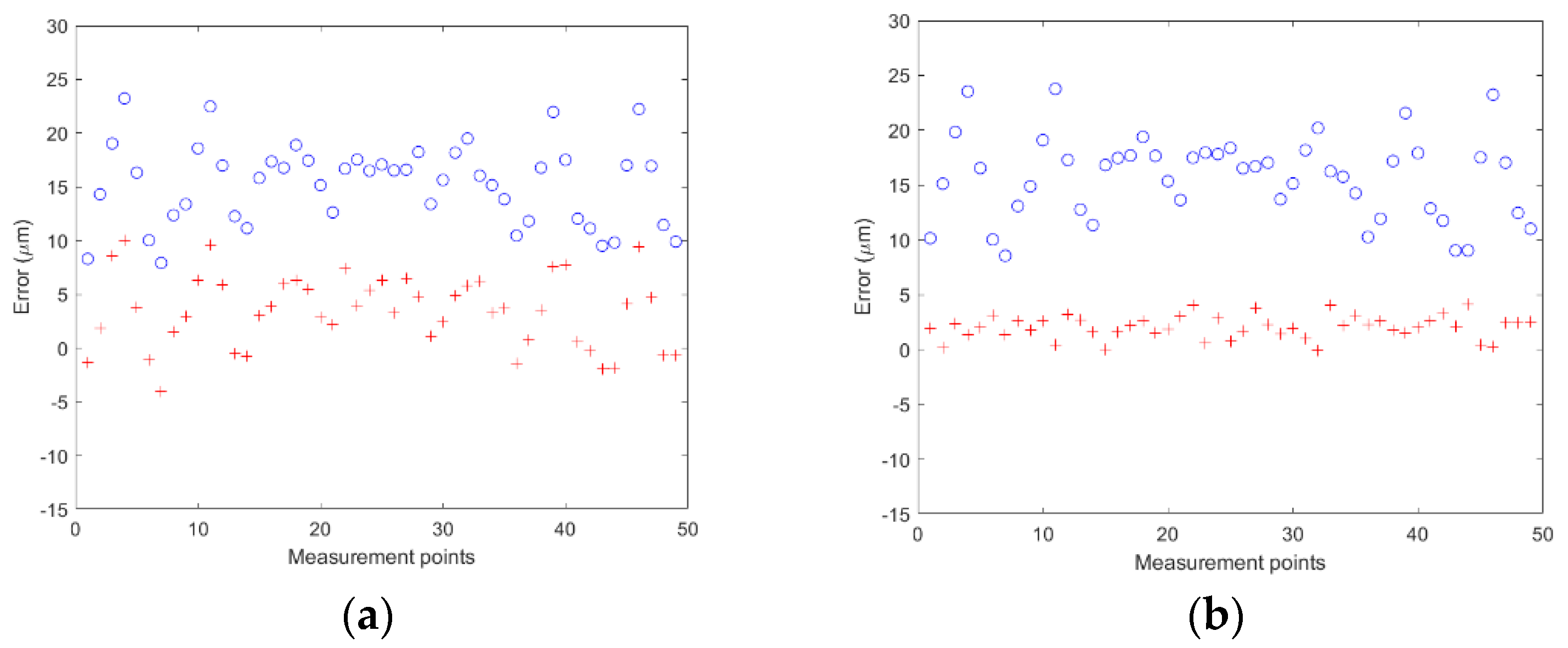
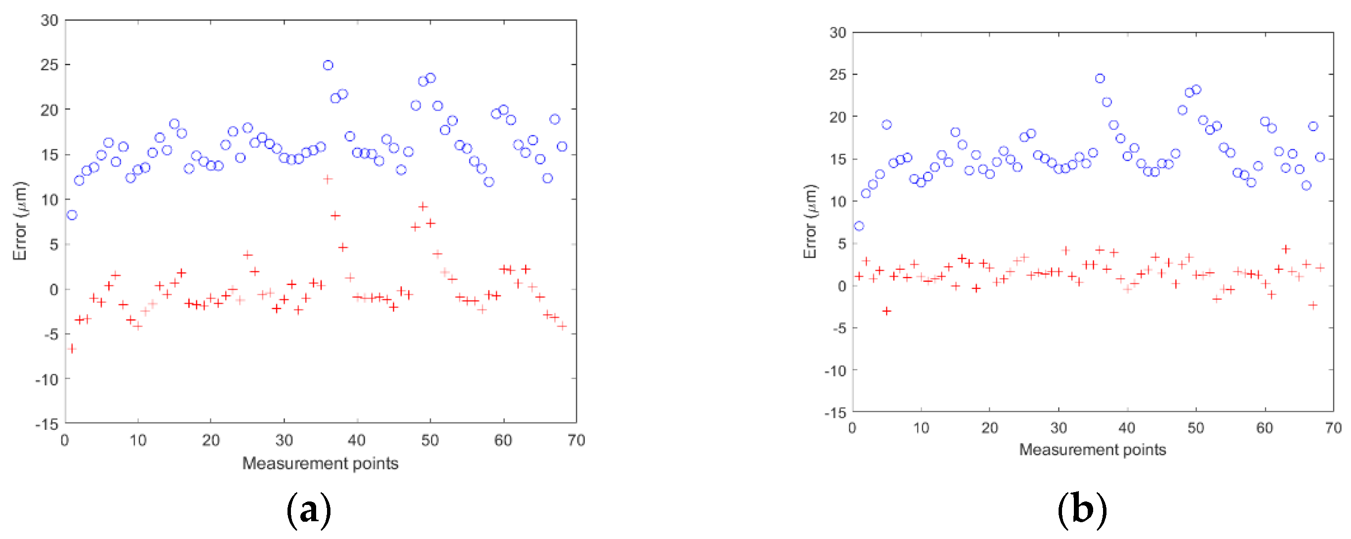
Similar to the experiments on Surface one, we also experimented with Surface two and Surface three.
Figure 11 and
Figure 12 show the error distributions for one of the replicas before and after compensation on Surfaces two and three, respectively.
The experimental results are summarized in
Table 3. As mentioned previously, Surfaces one, two, and three had 70, 49, and 68 measurement points for each replica, respectively, and each surface design had four replicas, so the number of errors for Surface one, two, and three was 280, 196, and 272, respectively. We used the errors to calculate the mean and standard deviation of the errors for each surface design, and the results are listed in
Table 3. For all the three different surfaces, it can be seen that both compensation methods can greatly improve the mean errors. The mean errors can be reduced to be within 2.0 μm or less for both methods. Regarding the standard deviations for Surfaces one, two, and three, the standard deviations after using mirror compensation improved by 3.8 μm, 2.3 μm, and 1.0 μm, which was equivalent to 61%, 61%, and 32%. The standard deviation can only improve by 0.1 μm by using the tool radius compensation for all three surfaces. It is evident that to improve the standard deviation of the error, the mirror compensation method proposed in the paper is more effective compared to the tool radius compensation method.
Regarding the different types of surface, Surface one is the least complicated surface, and Surface three is the most complicated one, as discussed previously. Intuitively, we expected Surface three to have the largest standard deviation of the errors and Surface one the smallest before error compensation. However, the actual standard deviations of errors were not as expected. Surface one had the largest variation. The reason for this phenomenon is unknown.
We also used the surface profile per ISO standard 1101 as a measure for evaluating the two compensation methods, and the results are summarized in
Table 4. For Surfaces one, two, and three, the surface profile error after using tool radius compensation could be improved by 24.8 μm, 32.3 μm, and 30.5 μm, which were equivalent to 45%, 62%, and 56%, respectively. However, using mirror compensation could improve the surface profile error by 44.8 μm, 44.4 μm, and 41.2 μm, which were equivalent to 78%, 84%, and 77%, respectively. For Surfaces one, two, and three, the mirror compensation method outperformed the tool radius compensation method by 33%, 22%, and 21%, respectively. It is obvious that for improving the surface profile error, the mirror compensation method proposed in the paper is also more effective than the tool radius compensation method.
4. Conclusions
An efficient and effective method to compensate for the errors of free-form surfaces is needed in the current machining industry. In this study, we developed a program based on mirror compensation by using the API function of NX, a CAD/CAM system, to integrate the machining, measurement, and compensation. After performing the semi-finishing machining, we used on-machine measurement to obtain the locations of the measurement points, which were then mirrored to generate the locations of the compensation points. The points were used to construct a new surface in CAD to allow NX to generate the tool paths for finishing machining. Five functions in NX for surface fitting were evaluated, and the function, Through Curve Mesh, performed the best. Experiments on three different free-form surfaces were conducted, and the average standard deviations of the errors of the compensated surfaces can be reduced by 61%, 61%, and 32%, respectively, compared to those of the uncompensated surfaces. Although the popular tool radius compensation method can reduce the mean of the errors, it can only reduce the standard deviation of the errors by a little. In terms of the surface profile error defined in ISO 1011, the mirror compensation method proposed in the paper outperformed the tool radius compensation method by at least 21%. Based on the results, the mirror compensation method proposed in the paper can provide an effective way to reduce the variation and surface profile error of the machined free-form surface.
The program can complete the error compensation and generate the tool paths for finishing machining in about 30 s on a regular PC, which means that the processing time and technical difficulty can also be reduced significantly.


