Article

Dynamic Responses of Liquid Storage Tanks Caused by Wind and Earthquake in Special Environment

1
Western Engineering Research Center of Disaster Mitigation in Civil Engineering of Ministry of Education, Lanzhou University of Technology, Lanzhou 730050, China
2
School of Civil Engineering & Mechanics, Huazhong University of Science and Technology, Wuhan 430074, China
*
Author to whom correspondence should be addressed.
Appl. Sci. 2019, 9(11), 2376; https://doi.org/10.3390/app9112376
Submission received: 24 April 2019 / Revised: 26 May 2019 / Accepted: 3 June 2019 / Published: 11 June 2019
(This article belongs to the Special Issue Buildings and Structures under Extreme Loads)

Abstract

:
Based on potential flow theory and arbitrary Lagrangian–Eulerian method, shell–liquid and shell–wind interactions are solved respectively. Considering the nonlinearity of tank material and liquid sloshing, a refined 3-D wind–shell–liquid interaction calculation model for liquid storage tanks is established. A comparative study of dynamic responses of liquid storage tanks under wind, earthquake, and wind and earthquake is carried out, and the influences of wind speed and wind interference effect on dynamic responses of liquid storage tank are discussed. The results show that when the wind is strong, the dynamic responses of the liquid storage tank under wind load alone are likely to be larger than that under earthquake, and the dynamic responses under wind–earthquake interaction are obviously larger than that under wind and earthquake alone. The maximum responses of the tank wall under wind and earthquake are located in the unfilled area at the upper part of the tank and the filled area at the lower part of the tank respectively, while the location of maximum responses of the tank wall under wind–earthquake interaction is related to the relative magnitude of the wind and earthquake. Wind speed has a great influence on the responses of liquid storage tanks, when the wind speed increases to a certain extent, the storage tank is prone to damage. Wind interference effect has a significant effect on liquid storage tanks and wind fields. For liquid storage tanks in special environments, wind and earthquake effects should be considered reasonably, and wind interference effects cannot be ignored.

1. Introduction

With the development of economy and society, more and more liquid storage tanks are built in seismically active areas, in extreme cases, these areas may also belong to strong wind areas, which leads to the threat of wind and earthquake to large-scale liquid storage tanks in the whole life cycle. Moreover, earthquake and wind-induced damage cases of liquid storage tanks are very common [1,2,3], two cases corresponding to earthquake and wind are shown in Figure 1. The destruction of the liquid storage tank not only involves the structure itself, but it will also cause huge economic losses, environmental pollution, fire, and so on, and even threaten people’s safety.
Dynamic responses of liquid storage tanks during earthquakes involves shell–liquid interaction, Rawat et al. [3] used a coupled acoustic–structural (CAS) approach in the FEM for the analysis of the tanks with rigid and flexible walls with varying parameters. Kotrasov et al. [4] simulated the interaction between structure and liquid on the contact surface based on the bidirectional fluid–solid coupling technique and studied the dynamic responses of liquid storage tanks by finite element method. Gilmanov et al. [5] proposed a numerical method to simulate the shell–liquid interaction of elastic thin plate with arbitrary deformation in incompressible fluid. In addition, a large number of studies and post-earthquake investigations show that the failure modes of liquid storage tanks under earthquake basically include liquid overflow, bottom lifting, circumferential tension, and instability. Ishikawa et al. [6] proposed a practical analytical model for shallow excited tank, which exhibited complex behavior because of nonlinearity and dispersion of the liquid. Moslemi et al. [7] conducted nonlinear sloshing analysis of liquid storage tanks and found that the sloshing nonlinearity had a significant effect on the seismic performance of liquid containing structures. Miladi and Razzaghi [8] performed numerical analysis of oil tank by using ABAQUS software, and carried out parametric study to evaluate the effect of amount of stored liquid on seismic behavior and performance of the studied tank. Ormeño et al. [9] performed shake table experiments to investigate the effects of a flexible base on the seismic response of a liquid storage tank, results showed that the axial compressive stresses decreased after a flexible base was considered. Sanapala et al. [10] performed shake table experiments to study the fluid structure interaction effects between the sloshing liquid and the internal structure, and found that when the partially filled storage tank was subjected to seismic excitation, spiky jet-like features were observed over the free surface. Rawat et al. [11] investigated three-dimensional (3-D) ground-supported liquid storage tanks subjected to seismic base excitation by using finite element method based on coupled acoustic–structural and coupled Eulerian–Lagrangian approaches. Generally speaking, dynamic responses of liquid storage tank involves complex fluid–structure interaction, and numerical simulation is an effective means to solve this problem.
Researchers have made certain explorations on the behavior of liquid storage tanks under wind load. Flores and Godoy [12] used numerical methods to study the buckling problem of liquid storage tanks under typhoon, and obtained that bifurcation buckling analysis could better evaluate the critical state of liquid storage tanks. Portela and Godoy [13] used computational model to evaluate the buckling behavior of steel tanks under wind loads. Zhang et al. [14] studied the dynamic responses of flexible liquid storage structure under wind load by multi-material ALE finite element method. Yasunaga et al. [15] used wind tunnel testing and finite element method to study the buckling behavior of thin-walled circular liquid storage tanks, and discussed the effect of wind load distribution on the buckling of liquid storage tanks by comparing it with a static wind load. Chen and Rotter [16] used finite element method to study the buckling of anchored liquid storage tanks with equal wall thickness under wind load. Zhao et al. [17] and Lin et al. [18] used wind tunnel tests to study the distribution of wind pressure and the stability of liquid storage tanks under wind loads.
In view of the structural dynamic response under the combined action of wind and earthquake, Hong and Gu [19] found that for high-flexible structures whose horizontal loads are controlled by wind load, the combined total loads after considering wind and earthquake loads may be more disadvantageous than those when considering wind loads in seismic design. Ke et al. [20] obtained that the structure responses of super-large cooling tower varied significantly along with height under wind load, earthquake, and wind–earthquake. Peng et al. [21] used the method of combining theoretical analysis with numerical simulation to get the position of maximum stress under wind load and earthquake action is different. Sapountzakis et al. [22] studied the nonlinear responses of wind turbine under wind load and earthquake. Mazza [23] synthesized velocity time history of wind based on equivalent spectrum technology, and studied the dynamic responses of steel frame structures under wind load and earthquake action.
To sum up, the dynamic responses of structures under earthquake and wind are obviously different, and the combined action of wind and earthquake will have more adverse effects on the structures, but the research on dynamic responses of liquid storage tanks under wind and earthquake is rare. In this paper, the shell–liquid and the shell–wind interactions are considered, and a refined calculation model of the liquid storage tank is established. The dynamic responses of the liquid storage tank under wind, earthquake, and wind and earthquake are studied in many aspects, which is of great significance to the rationality of the design and the reliability of the operation of the liquid storage tank.

2. Wind Field Control Equations

Large eddy simulation (LES) is used to calculate the wind field, and its control equation is
u ˙ ¯ i t + u ˙ ¯ i u ˙ ¯ j x j = 1 ρ p ¯ x i ν 2 u ˙ ¯ i x j x j + τ ¯ i j x j
u ˙ ¯ i x i = 0
where τ ¯ i j = u ˙ ¯ i u ˙ ¯ j u ˙ i u ˙ j ¯ , τ ¯ i j is subgrid-scale stress, namely, SGS stress, which reflects the influence of the motion of small-scale vortices on the motion equation.
If the equations consisting of Equations (1) and (2) are closed, then according to Smagorinsky’s basic SGS model, it is assumed that the SGS stress satisfies the following requirements
τ ¯ i j 1 3 τ ¯ k k δ i j = 2 μ t S ¯ i j
μ t = ( C s Δ ) 2 | S ¯ |
where S ¯ i j = 1 2 ( u ¯ i x j + u ¯ j x i ) , | S ¯ | = 2 S ¯ i j S ¯ i j , Δ = ( Δ x Δ y Δ z ) 1 / 3 , μ t is turbulent viscosity at sublattice scale, Δ is filtration scale of large eddy model, Δ i represents the grid size along the i-axis, C s Δ is equivalent to mixing length, C s is SGS constant.

3. Structure Control Equations

The structure equation of motion is
M s s u ¨ s + C s s u ˙ s + K s s u s = F s s
where Mss, Css, and Kss are mass, damping and stiffness matrices of structures, respectively; Fss is load vector acting on structure, which includes liquid pressure; u ¨ s , u ˙ s , and u s are vectors of acceleration, velocity, and displacement of structure, respectively.
Newmark method is used to solve the dynamic Equation (5), and the first assumption is
u ˙ s ( i + 1 ) = u ˙ s ( i ) + [ ( 1 β ) u ¨ s ( i ) + β u ¨ s ( i + 1 ) ] Δ t
u s ( i + 1 ) = u s ( i ) + u ˙ i Δ t + [ ( 1 2 γ ) u ¨ i + γ u ¨ i + 1 ] Δ t 2
where β and γ are adjustment coefficients for accuracy and stability.
The incremental forms Δ u ˙ s and Δ u s of velocity u ˙ s and displacement u s can be obtained from Equations (6) and (7), respectively
Δ u ˙ s ( i ) = u ˙ s ( i + 1 ) u ˙ s ( i ) = ( u ¨ s ( i ) + β Δ u ¨ s ( i ) ) Δ t
Δ u s ( i ) = u s ( i + 1 ) u s ( i ) = u ˙ s ( i ) Δ t + 1 2 u ¨ s ( i ) Δ t 2 + γ Δ u ¨ s ( i )
Acceleration increment Δ u ¨ i can be obtained by transforming Equation (9), then taking Δ u ¨ i into Equation (8)
Δ u ¨ i = 1 γ Δ t 2 Δ u i 1 γ Δ t u ˙ i ( 1 2 γ 1 ) u ¨ i
Δ u ˙ i = β γ Δ t Δ u i + ( 1 β γ ) u ˙ i + ( 1 β 2 γ ) Δ t u ¨ i
The incremental form corresponding to Equation (5) is
M s s Δ u ¨ s ( i ) + C s s Δ u ˙ s ( i ) + K s s Δ u s ( i ) = Δ F s s ( i )
Taking Equations (9)–(11) into Equation (12)
K ¯ Δ u s ( i ) = F ¯
where K ¯ = K + 1 γ Δ t 2 M + β γ Δ t C ; F ¯ = Δ F s s ( i ) + M [ 1 γ Δ t u ˙ i + ( 1 2 γ 1 ) u ¨ i ] + C [ ( β γ 1 ) u ˙ i + ( β 2 γ 1 ) Δ t u ¨ i ] .
The displacement increment Δ u s ( i ) can be obtained by Equation (13), velocity increment Δ u ˙ s ( i ) can be obtained by substituting displacement increment Δ u s ( i ) into Equation (11). As a result, the displacement u s ( i + 1 ) and velocity u ˙ s ( i + 1 ) of i + 1 time step can be obtained
u s ( i + 1 ) = u s ( i ) + Δ u s ( i )
u ˙ s ( i + 1 ) = u ˙ s ( i ) + Δ u ˙ s ( i )
The acceleration u ¨ s ( i + 1 ) of time step i + 1 can be obtained by substituting Equations (14) and (15) into Equation (5)
u ¨ s ( i + 1 ) = M s s 1 [ F s s C s s u ˙ s ( i + 1 ) K s s u s ( i + 1 ) ]

4. Fluid–Solid Interaction

In order to overcome the defects of large calculation amount and low calculation efficiency, the potential flow theory is used to solve the shell–liquid interaction, and the arbitrary Lagrangian–Eulerian method is used to solve the shell–wind interaction.

4.1. Shell–Liquid Interaction

Because the calculation process involves a large number of nonlinearities, the exact solution of each response can be obtained through multiple equilibrium iterations. Δϕ is used to express the increment of the unknown velocity potential ϕ, and Δu is used to express the increment of the unknown displacement u. The shell–liquid interaction dynamic equation based on potential fluid theory is [24]
[ M s s 0 0 M l l ] [ Δ u ¨ Δ ϕ ¨ ] + [ C u u + C s s C u l C l u ( C l l + ( C l l ) S ) ] [ Δ u ˙ Δ ϕ ˙ ] + [ K u u + K s s K l u K u l ( K l l + ( K l l ) S ) ] [ Δ u Δ ϕ ] = [ F s s 0 ] [ F p F l + ( F l ) S ]
where Mll is the liquid mass matrix; Cuu, Clu, Cul, and Cll are the damping matrices of the structure itself, the liquid contributed by the structure, the structure contributed by the liquid and the liquid itself, respectively; and Kuu, Klu, Kul, and Kll are the stiffness matrices of the structure itself, the liquid contributed by the structure, the structure contributed by the liquid and the liquid itself, respectively; Fp, Fl, and (Fl)S are the forces acting on the structural boundary caused by the liquid pressure, volume force, and area force, respectively; Fl is obtained by the volume integral of Equation (18), and (Fl)S is obtained by surface integral of Equation (19) [24]
F l = V ( ρ l h h ˙ δ ϕ ρ l ϕ ) d V
( F l ) S = S ρ l u n δ ϕ d S
where ρl is the liquid density; V is the liquid domain; S is the liquid domain boundary; n is the internal normal direction vector of S; and u ˙ is the moving speed of the boundary surface S.
The boundary surface adjacent to the structure is represented as S1, and the force acting on structure boundary Fp caused by the liquid pressure can be expressed as Equation (20)
δ F p = S 1 p n δ u d S 1
where δ F U is differentiation of additional forces caused by liquid; n is normal vector of adjacent interface. Liquid pressure p is calculated by Equation (21)
p = p ( h ) = p [ Ω ( x + u ) ϕ ˙ 1 2 v n v n 1 2 v τ v τ ]
where Ω is volume acceleration potential energy; vn and vτ are liquid normal and tangential velocities on the interaction boundary.

4.2. Shell–Wind Interaction

The wind field equation and the structure equation are expressed by G w [ w , w ˙ ] = 0 and G s [ u , u ˙ , u ¨ ] = 0 , respectively, subscript w denotes wind field variables, and subscript s denotes structure variables.
Firstly, the velocity and acceleration of wind field are expressed as [25]
v t + α Δ t = t + α Δ t u u t t = v t + Δ t α + v t ( 1 α ) a t + α Δ t = t + α Δ t v v t t = a t + Δ t α + a t ( 1 α )
where α is stability conditions of compatible time integral.
Velocity and acceleration of Equation (22) at t + Δt can be expressed as functions of unknown displacement
v t + Δ t = 1 α Δ t ( u t + Δ t u t ) v t ( 1 α 1 ) = d t + Δ t m + ξ t a t + Δ t = 1 α 2 Δ t 2 ( u t + Δ t u t ) v t 1 α 2 Δ t a t ( 1 α 1 ) = d t + Δ t n + η t
Taking Equations (22) and (23) into wind field equation G w [ w , w ˙ ] = 0 and structure equation G s [ u , u ˙ , u ¨ ] = 0
G t + α Δ t w G w [ w t + α Δ t , ( w t + α Δ t w t ) / α Δ t ] = 0 G t + Δ t s G s [ u t + Δ t , d t + Δ t m + ξ t , d t + Δ t n + η t ] = 0
In order to solve the coupled system, Equation (24) is discretized. Assuming that the solution vector of the coupled system is X = X(Xw, Xs), Xw, and Xs represents solution vectors of wind field and structure nodes. Therefore, us = us(Xs) and τw = τw(Xw), and the shell–wind coupling equation can be expressed as [25]
G f [ X w k , λ d u s k + ( 1 λ d ) u s k 1 ] = 0 G s [ X s k , λ τ τ w k + ( 1 λ τ ) τ w k 1 ] = 0
where λd and λτ are displacement and stress relaxation factors.
The above solving process can be illustrated by Figure 2.

5. Boundary Conditions

5.1. Wind Field Boundary Conditions

For high Reynolds number incompressible steady flow, velocity-inlet is chosen as the boundary condition at the entrance; pressure-outlet without backflow is chosen as the boundary condition at the outlet, that is, at the exit boundary of the flow field, the diffusion flux of the physical quantity of the flow field along the normal direction of the exit is 0; the non-slip wall boundary is used as boundary condition on the structure surface and ground. Symmetry is chosen as the boundary on both sides and on the top. The boundary conditions for wind field simulation are shown in Figure 3.

5.2. Shell–Liquid Interaction Boundary Conditions

The conditions of displacement continuity and force balance need to be satisfied at the shell–liquid interaction interface, namely
u s = u l , F s = F l
where u s and u l are structure and liquid displacement vectors; F s and F l are structure and liquid dragging forces.
F s = σ s n s ,   F l = σ l n l
where ns and nl are interface normal vector; σ s and σ l are structure and liquid stress vectors.

6. Numerical Example

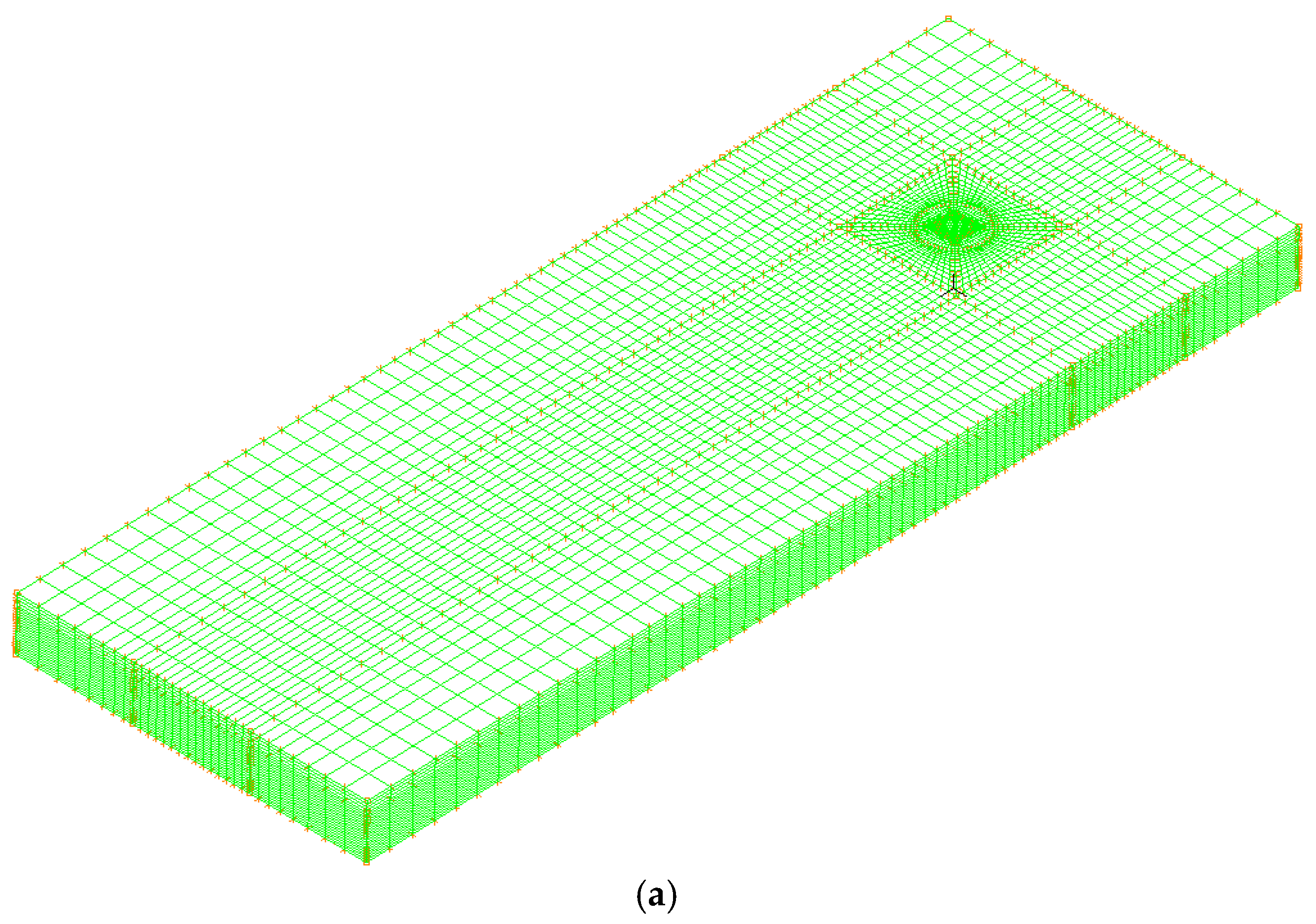
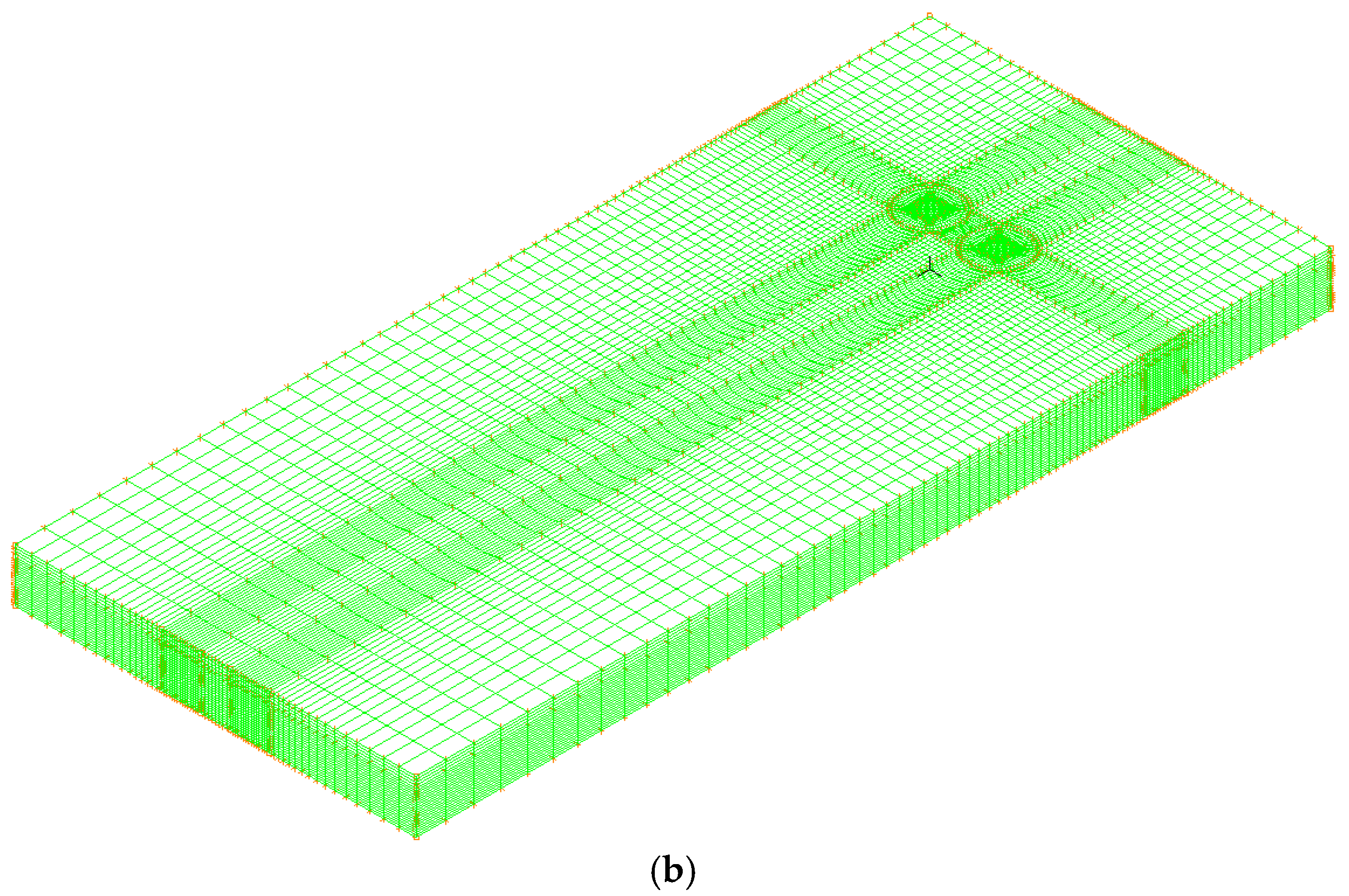
6.1. Calculation Model

The diameter and height of the tank are 21 m and 16 m, liquid storage height is 8 m. The wall thickness from the bottom to the top is as follows: 0–2 m is 14 mm; 2–4 m is 12 mm; 4–6 m is 10 mm; 6–10 m is 8 mm; and 10–16 m is 6 mm. Bilinear elastic-plastic material and shell elements are used to simulate a liquid storage tank, potential fluid material model and 3D solid element are used to simulated liquid, and liquid free surface is defined to reflect liquid sloshing behavior. El-Centro wave is selected as the ground motion input for time-history analysis.
Since there are a large number of liquid storage tanks in actual oil depots, it is necessary to study the influence of wind interference effect. By comparing the dynamic responses of single tanks and double tanks under wind load, the influence of wind interference effect on liquid storage tanks can be preliminarily discussed. Wind field is simulated by using 8-node 6-hedral FCBI-C element and large-eddy-simulation material. The calculation model material parameters are shown in Table 1, and the calculation model are shown in Figure 4 and Figure 5.

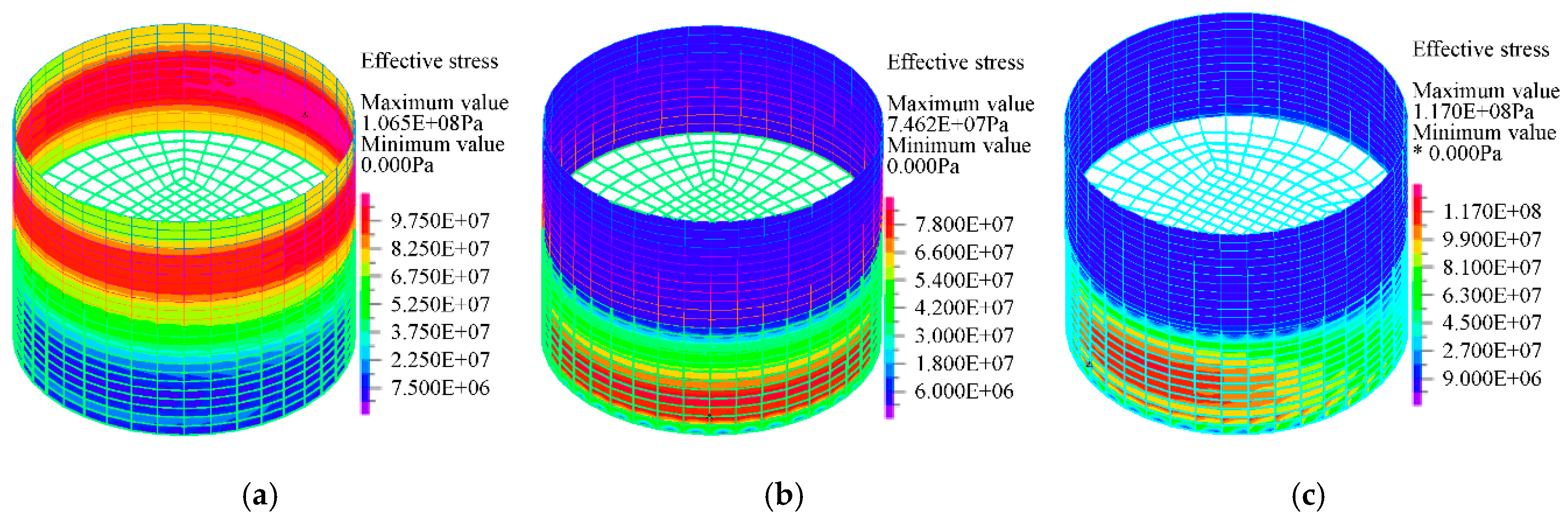
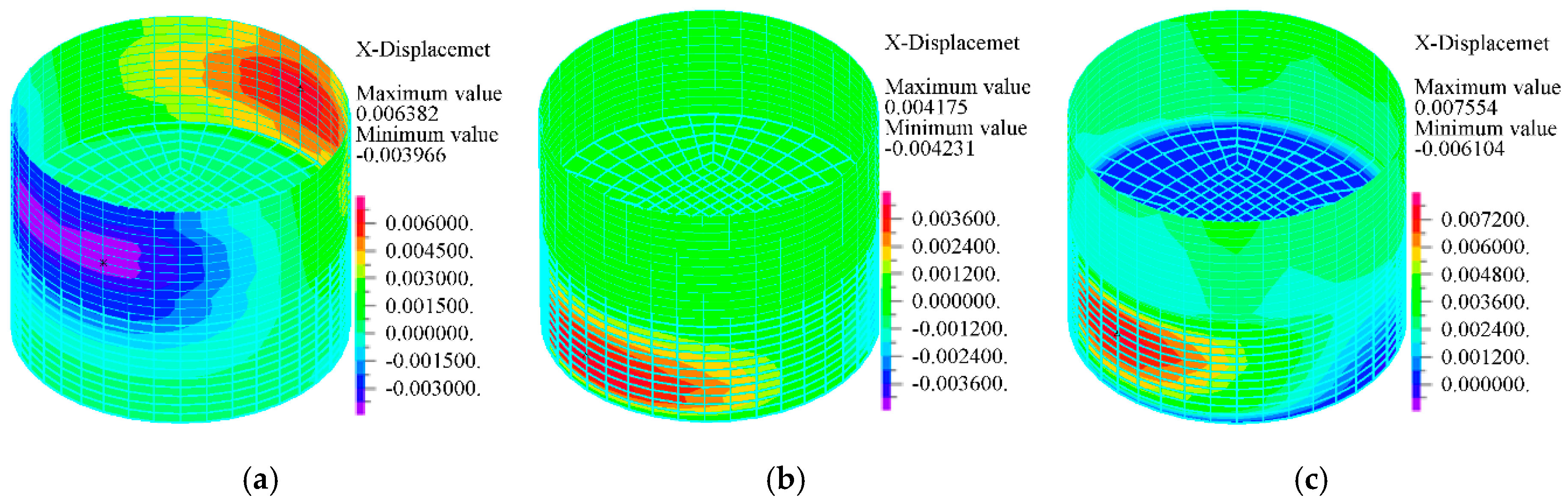
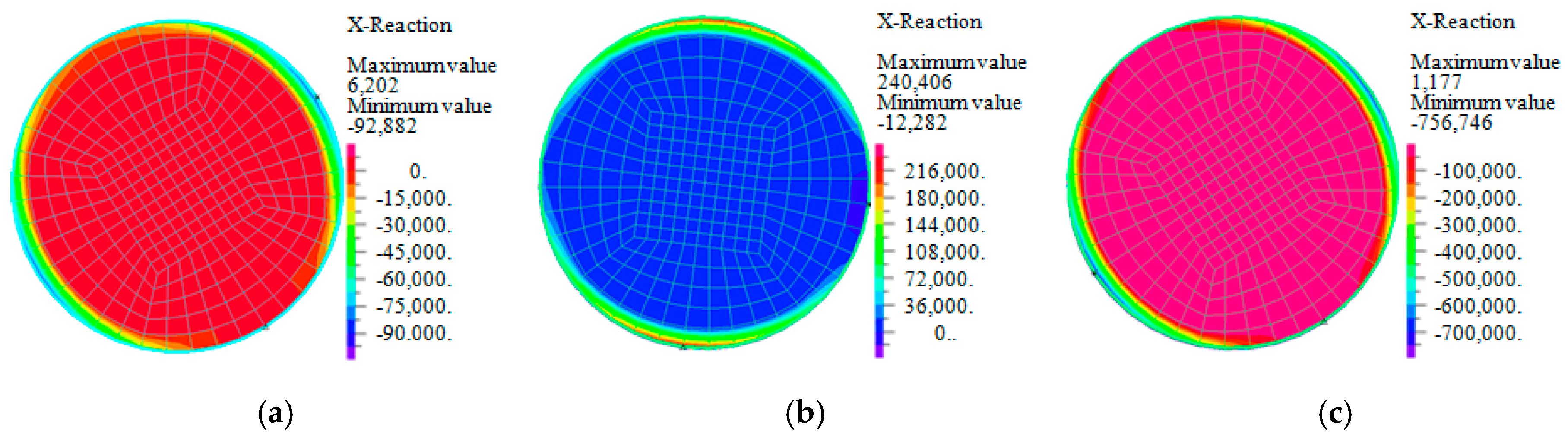
6.2. Comparison of Dynamic Responses under Different Actions

In view of the possibility that the liquid storage tank may be damaged under the action of wind and earthquake, and the combined action of wind and earthquake will have more adverse effects on the structure, a comparative study on the dynamic response of the liquid storage tank under the action of wind, earthquake, and wind and earthquake is carried out, and the specific results are shown in Figure 6, Figure 7 and Figure 8 and Table 2.
As shown in Figure 6, Figure 7 and Figure 8, the maximum effective stress and displacement of tank under wind load is located in the unfilled area of the upper part of the liquid storage tank, while the maximum effective stress and displacement of the structure under earthquake is located in the filled area of the lower part of the liquid storage tank, and the maximum of base shear force appears near the contact position between the tank wall and foundation.
As shown in Table 2, it can be seen that when the wind speed is larger, the effective stress and displacement under wind load is greater than that under earthquake. However, a large number of researches on liquid storage tanks have been carried out on the basis of considering only the earthquake action, so there are some defects. Besides, the dynamic responses of tank under the combined action of wind and earthquake are obviously greater than those under the separate action of wind and earthquake. The effective stress, displacement, and base shear force obtained by SRSS are 130.04 Mpa, 7.65 mm and 257.73, respectively, which are very different from considering the interaction of wind and earthquake at the same time.
Therefore, when the wind speed is large, the influence of wind load on the liquid storage tank cannot be ignored. The location of maximum dynamic responses of liquid storage tank under wind and earthquake is different, and the combined effect of wind and earthquake will have a more adverse impact on the liquid storage tank. Therefore, for the liquid storage tank in special areas (such as coastal areas), the combined effect of wind and earthquake should be reasonably considered in its design.

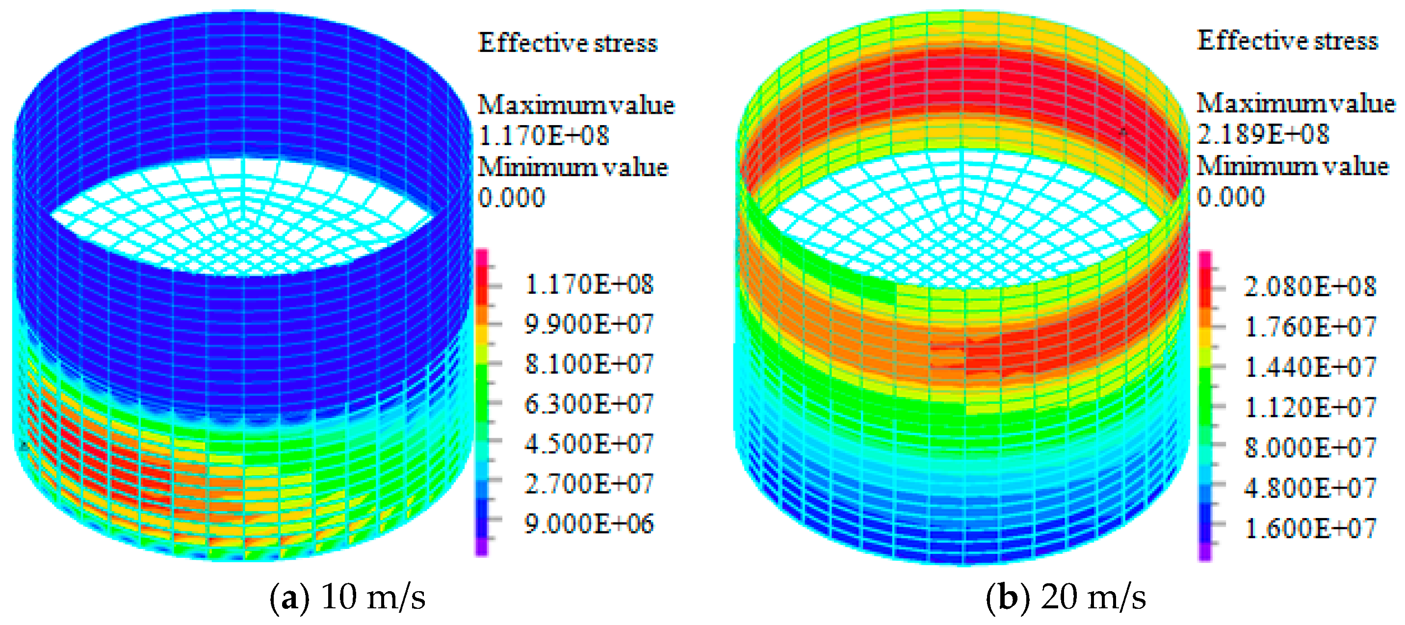
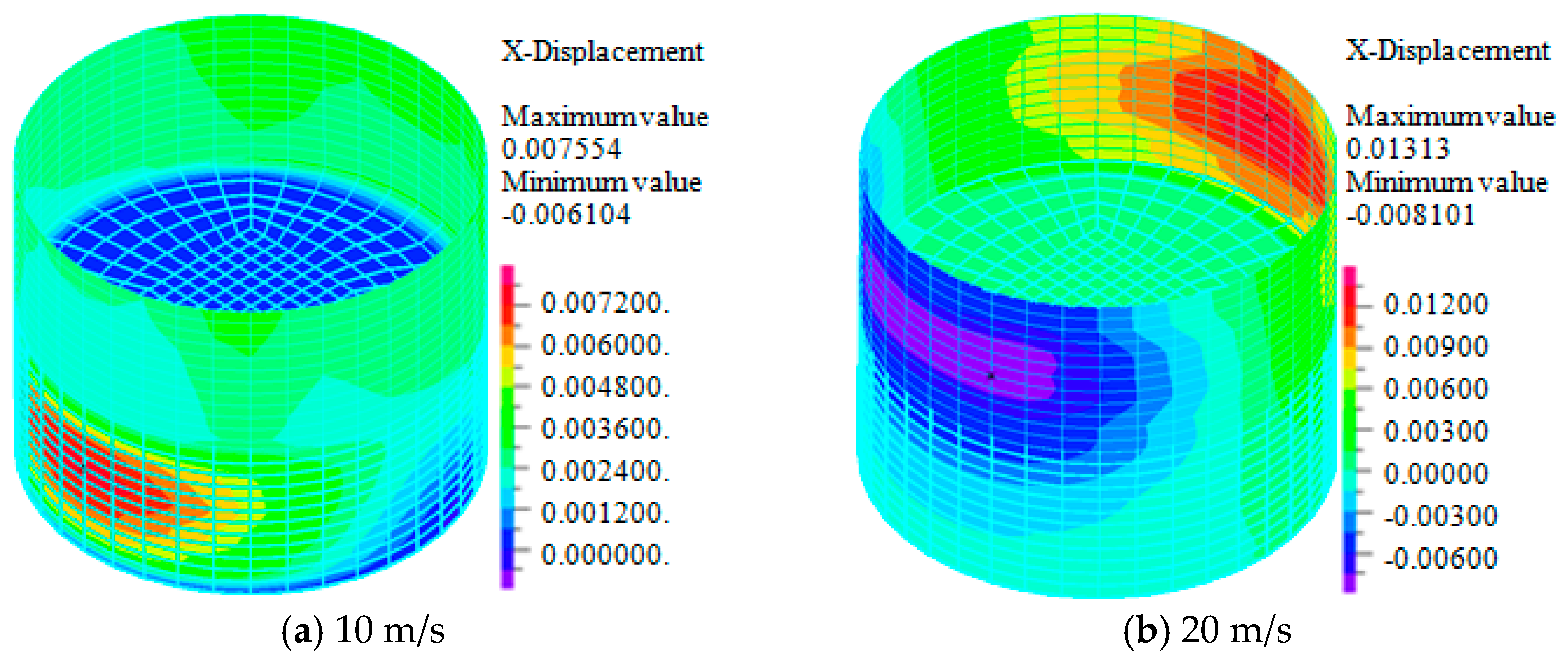
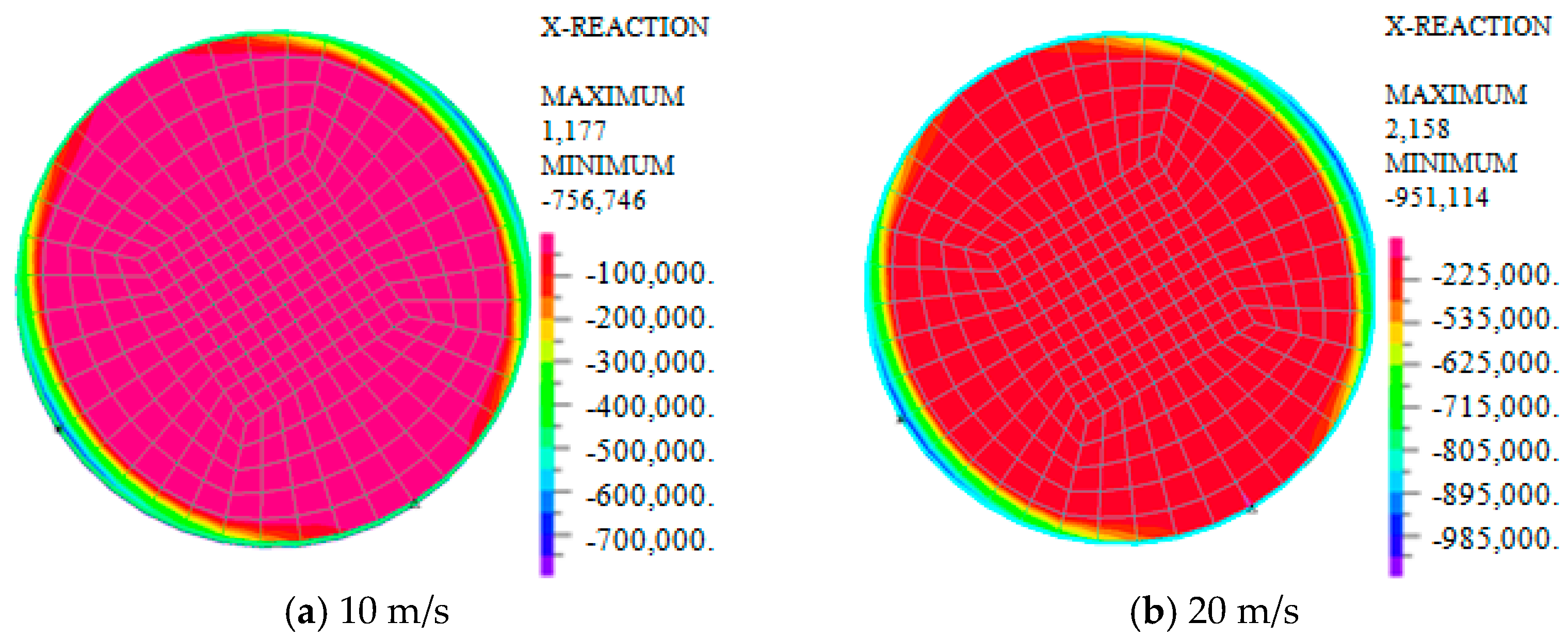
6.3. Influences of Wind Speed on Dynamic Responses

Through the above analysis, it has been found that the influence of wind load on the liquid storage tank cannot be ignored. In order to further discuss the responses of the liquid storage tank under wind load, a comparative study is carried out under the wind speed of 10 m/s and 20 m/s. The nephograms of the effective stress, displacement, and base shear force are shown in Figure 9, Figure 10 and Figure 11 and Table 3.
As shown in Figure 9, Figure 10 and Figure 11, under the combined action of wind and earthquake, when the wind speed is 10 m/s, the location of maximum effective stress and displacement of the tank is located in the liquid filled area at the bottom of the liquid storage tank, but when the wind speed increases to 20 m/s, the location of maximum effective stress and displacement of the structure shifts to the unfilled area at the upper part of the liquid storage tank. That is to say, when the wind speed is lower, the responses of liquid storage tanks are dominated by earthquake, on the contrary, when the wind speed is higher, the responses of liquid storage tanks will be dominated by wind.
As shown in Table 3, when the wind speed is increased by 2 times, the effective stress, displacement, and base shear force are significantly increased, especially the effective stress and displacement are approximately increased by 2 times.
Therefore, when the wind speed is high, the probability of damage to the liquid storage tank is relatively high. For liquid storage tanks built in special areas, sufficient attention should be paid to the adverse effects of wind load.

6.4. Wind Interference Effect

Significant wind disturbance effect exists in group structures, Zhao et al. [26] obtained that amplification effect caused by wind disturbance reaches to 20–40% through wind tunnel test. Zhang et al. [27] obtained that the unfavorable influence of double-row arrangement of towers is obviously larger than that of single-row arrangement.
Through the research on the influence of wind speed on the dynamic response of the structure, it is found that the larger the wind speed, the more unfavorable it is to the tank. Therefore, taking the wind speed of 20 m/s as an example, single tanks and double tanks are selected as research objects to study the influence law of wind interference effect on the dynamic responses of liquid storage tanks. The comparisons of effective stress, displacement, base shear force, and velocity field are shown in Figure 12, Figure 13, Figure 14 and Figure 15 and Table 4.
As shown in Figure 12, Figure 13, Figure 14 and Figure 15 and Table 4, without considering and considering the wind interference effect, the maximum absolute values of effective stress of the tank are 218.96 MPa and 233.81 MPa, respectively; the maximum absolute values of the displacement of the tank are 13.13 mm and 18.02 mm, respectively; the maximum absolute values of the base shear force of the tank are 951.11 kN and 1263.77 kN, respectively; and the maximum absolute values of the wind field speed are 35.59 m/s and 52.13 m/s, respectively. The difference ratios corresponding to effective stress, displacement, base shear force and wind velocity are 9.07%, 37.24%, 32.85%, and 46.47%.
For a single tank, the maximum dynamic response is located on the tank axis and the maximum wind speed is located near the tank walls on both sides; while for a double tank, the maximum dynamic response shifts to the side between the two tanks, and the maximum wind speed is located in the area between the two tanks.
It can be seen that the wind interference effect has a great influence on the dynamic response and wind field of liquid storage tanks. Liquid storage tanks in actual oil storage facilities are basically arranged side by side. In order to ensure their safety, it is necessary to consider the wind interference effect.

7. Conclusions

Considering shell–liquid interaction and shell–wind interaction, calculation model of liquid storage tanks is established. The dynamic responses of liquid storage tanks under wind, earthquake, and wind and earthquake are studied comparatively. Besides, the influences of wind speed and wind interference effect on the dynamic responses of the liquid storage tank are discussed. The main conclusions are as follows:
(1)
Although it is commonly believed that structure dynamic responses are usually dominated by either wind or earthquake, when wind speed is high, responses of liquid storage tanks under wind are greater than that under earthquake, besides, responses of liquid storage tanks under combination of wind and earthquake are more important. Results indicate that it is necessary to consider the combination of wind and earthquake actions in the design of liquid storage tank.
(2)
When wind speed increases from 10 m/s to 20 m/s, under combined action of earthquake and wind, tank dynamic responses are significantly increased; especially, tank wall stress is even close to the yield strength of steel (235 Mpa).
(3)
Liquid storage tanks have different performance under earthquake or wind, the maximum responses under wind load are located in the upper region without liquid filling, while the maximum responses under earthquake are located in the lower area of liquid storage tank; while the locations of maximum responses under combination of wind and earthquake are related to wind speed.
(4)
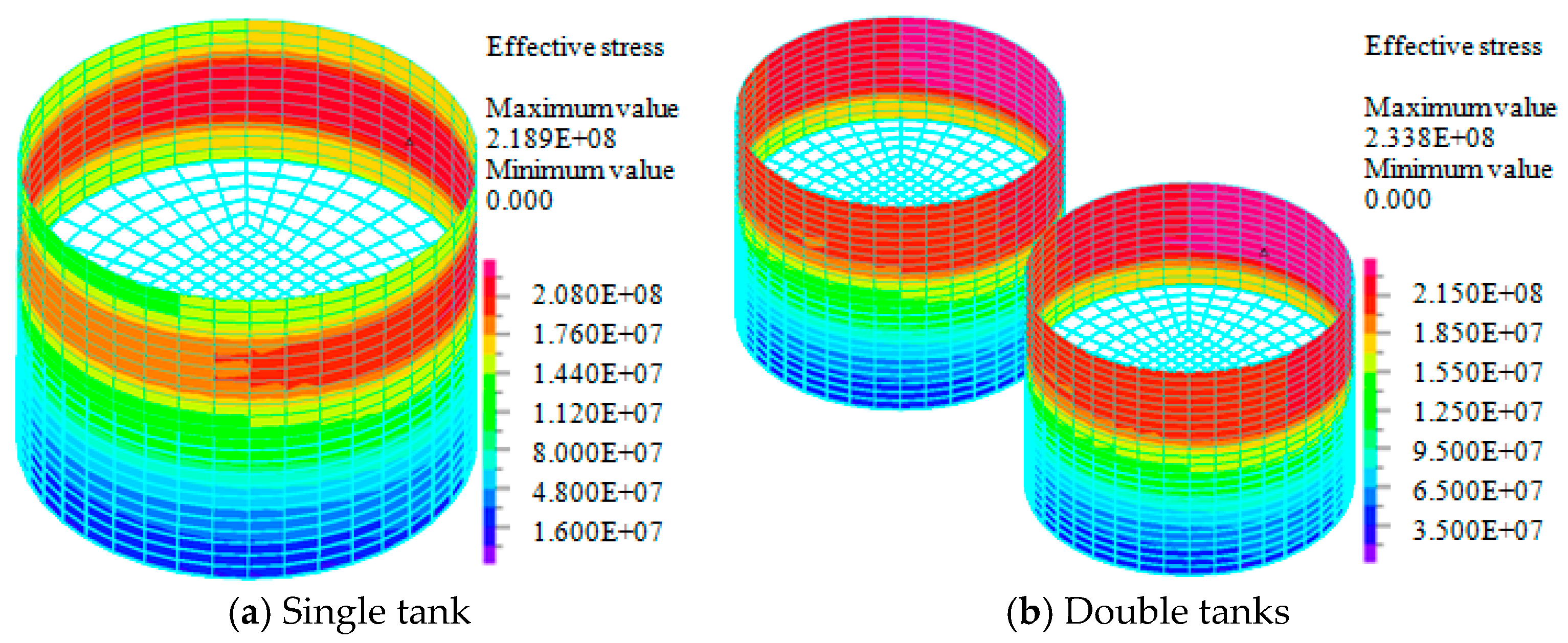
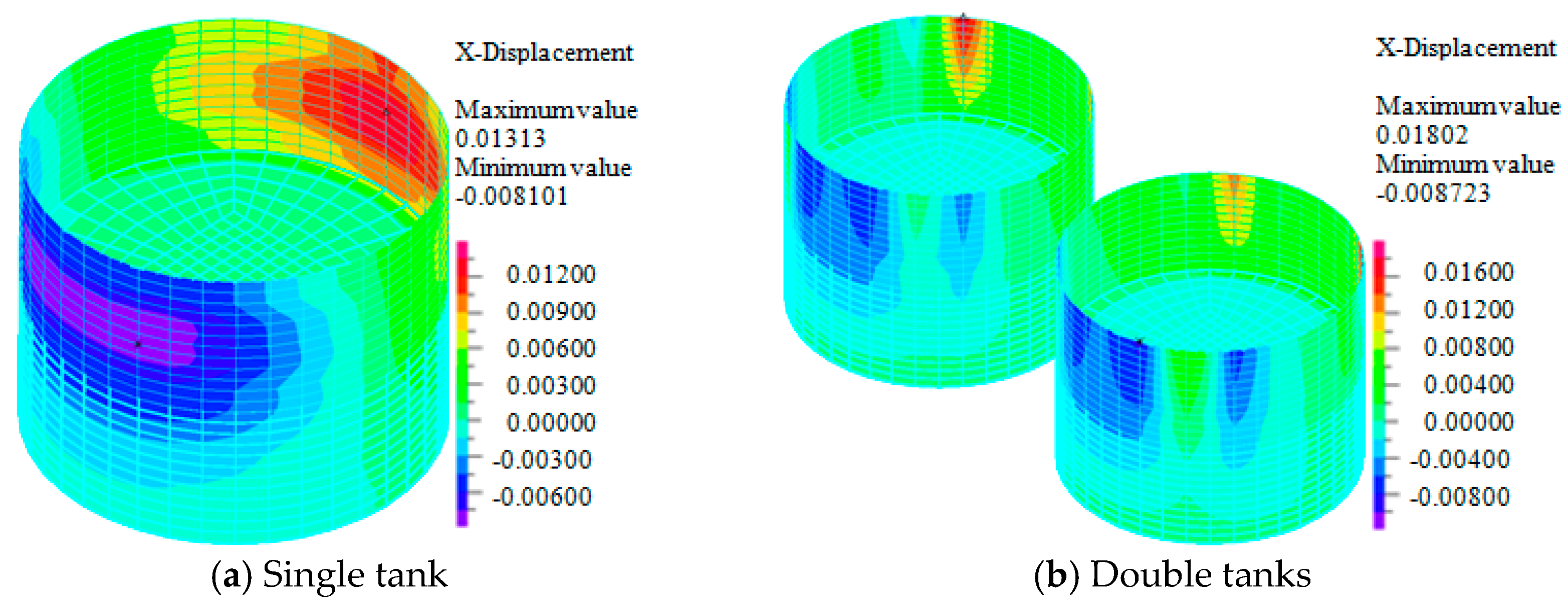
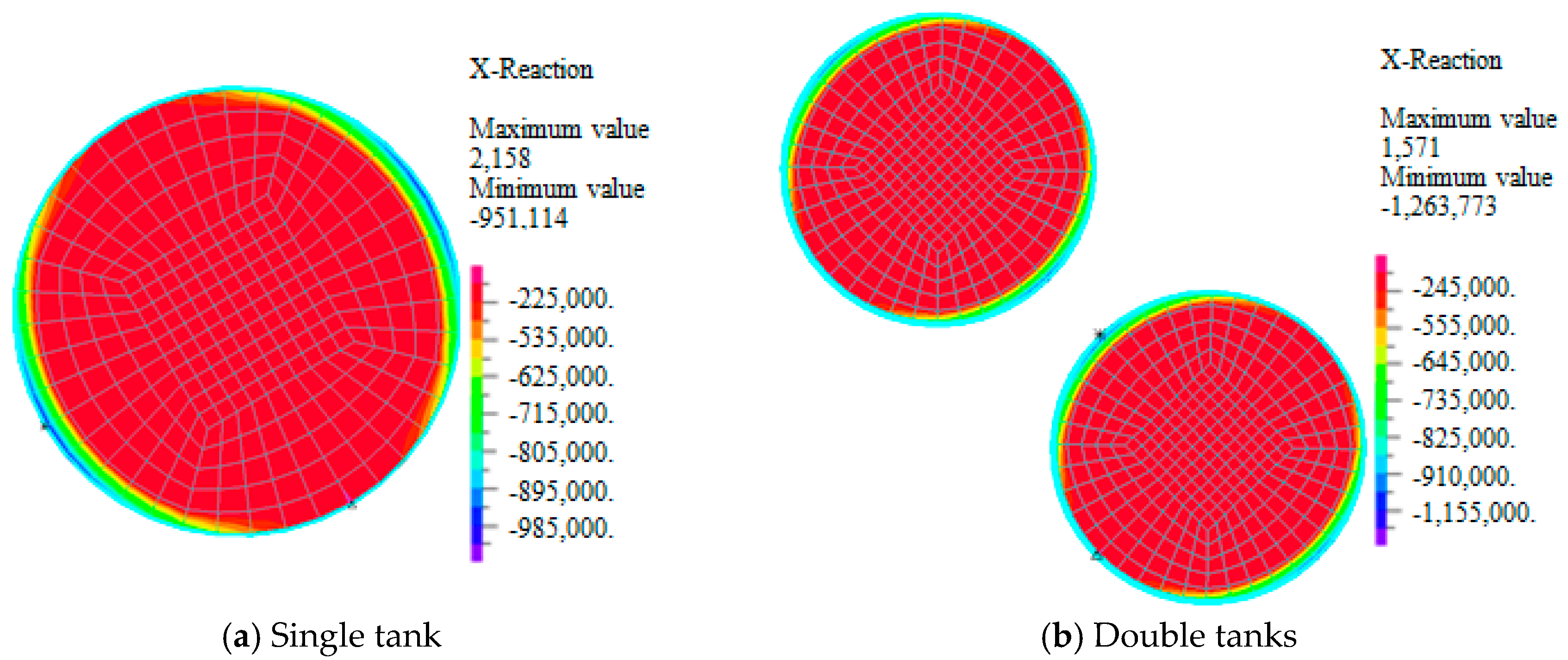
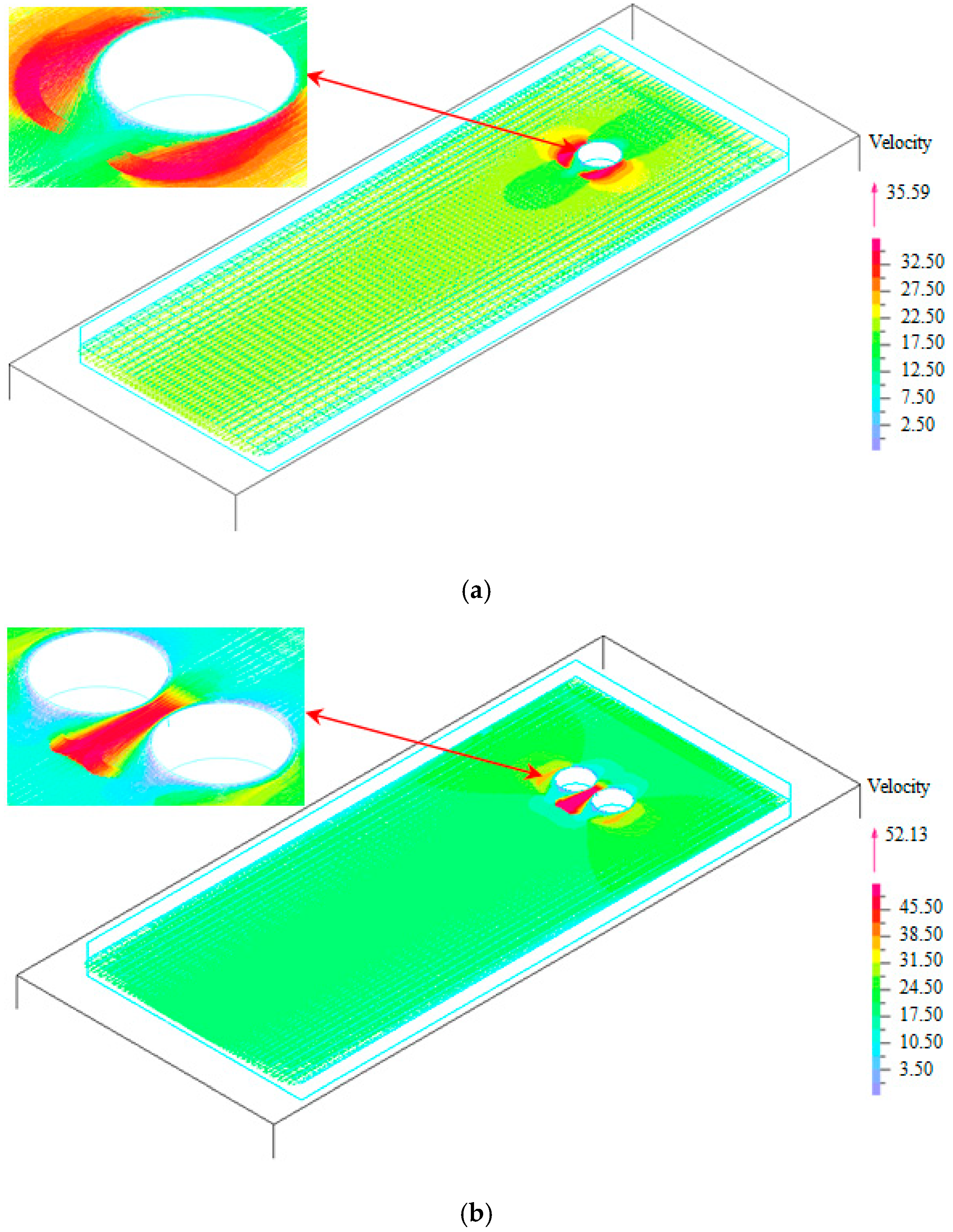
Wind disturbance effect has a significant influence on liquid storage tanks and the wind field, and the position of maximum response will be also changed after wind disturbance effect being considered. Besides, dynamic responses corresponding to double tanks are obviously larger than that of single tanks, it can be seen that if the wind disturbance effect is not considered, the responses will be underestimated.
(5)
In order to consider combination of wind and earthquake, the effective stress, displacement, and base shear force obtained by conducting SRSS for wind and earthquake alone conditions are very different from considering wind and earthquake at the same time.

Author Contributions

Methodology, W.J.; software, W.J. and H.F.; formal analysis, W.J. and H.F.; writing—original draft preparation, W.J.; writing—review and editing, X.C.

Funding

This paper is a part of the China Postdoctoral Science Foundation (grant no. 2018M633652XB), a part of the National Natural Science Foundation of China (grant no. 51368039), a part of the Hongliu Outstanding Young Talents Support Program of Lanzhou University of Technology (grant no. 04-061807) and a part of the Open Foundation of International Research Base on Seismic Mitigation and Isolation of Gansu Province (grant no. TM-QK-1904).

Conflicts of Interest

The authors declare no conflict of interest.

References

  1. Holroyd, R.J. On the behaviour of open-topped oil storage tanks in high winds. part II. structural aspects. J. Wind Eng. Ind. Aerod. 1983, 12, 329–352. [Google Scholar] [CrossRef]
  2. Vela, R.J.M.; Brunesi, E.; Nascimbene, R. Seismic assessment of an industrial frame-tank system: Development of fragility functions. Bull. Earthq. Eng. 2019, 17, 2569–2602. [Google Scholar] [CrossRef]
  3. Rawat, A.; Matsagar, V.A.; Nagpal, A.K. Numerical study of base-isolated cylindrical liquid storage tanks using coupled acoustic-structural approach. Soil Dyn. Earthq. Eng. 2019, 119, 196–219. [Google Scholar] [CrossRef]
  4. Kotrasová, K.; Grajciar, I.; Kormaníková, E. Dynamic time-history response of cylindrical tank considering fluid-structure interaction due to earthquake. Appl. Mech. Mater. 2014, 617, 66–69. [Google Scholar] [CrossRef]
  5. Gilmanov, A.; Le, T.B.; Sotiropoulos, F. A numerical approach for simulating fluid structure interaction of flexible thin shells undergoing arbitrarily large deformations in complex domains. J. Comput. Phys. 2015, 300, 814–843. [Google Scholar] [CrossRef] [Green Version]
  6. Ishikawa, S.; Kondou, T.; Matsuzaki, K.; Yamamura, S. Analysis of nonlinear shallow water waves in a tank by concentrated mass model. J. Sound Vib. 2016, 371, 171–182. [Google Scholar] [CrossRef]
  7. Moslemi, M.; Farzin, A.; Kianoush, M.R. Nonlinear sloshing response of liquid-filled rectangular concrete tanks under seismic excitation. Eng. Struct. 2019, 188, 564–577. [Google Scholar] [CrossRef]
  8. Miladi, S.; Razzaghi, M.S. Failure analysis of an un-anchored steel oil tank damaged during the Silakhor earthquake of 2006 in Iran. Eng. Fail. Anal. 2019, 96, 31–43. [Google Scholar] [CrossRef]
  9. Ormeño, M.; Larkin, T.; Chouw, N. Experimental study of the effect of a flexible base on the seismic response of a liquid storage tank. Thin-Walled Struct. 2019, 139, 334–346. [Google Scholar] [CrossRef]
  10. Sanapala, V.S.; Sajish, S.D.; Velusamy, K.; Ravisankar Patnaik, B.S.V. An experimental investigation on the dynamics of liquid sloshing in a rectangular tank and its interaction with an internal vertical pole. J. Sound Vib. 2019, 449, 43–63. [Google Scholar] [CrossRef]
  11. Rawat, A.; Mittal, V.; Chakraborty, T.; Matsagar, V. Earthquake induced sloshing and hydrodynamic pressures in rigid liquid storage tanks analyzed by coupled acoustic-structural and Euler-Lagrange methods. Thin-Walled Struct. 2019, 134, 333–346. [Google Scholar] [CrossRef]
  12. Flores, F.G.; Godoy, L.A. Buckling of short tanks due to hurricanes. Eng. Struct. 1998, 20, 752–760. [Google Scholar] [CrossRef]
  13. Portela, G.; Godoy, L.A. Wind pressures and buckling of cylindrical steel tanks with a dome roof. J. Constr. Steel Res. 2005, 61, 808–824. [Google Scholar] [CrossRef]
  14. Zhang, X.; Jin, X.L.; Chen, X.D. Numerical simulation of dynamic characteristics of flexible container under wind load. J. Vib. Shock 2009, 28, 115–118. [Google Scholar] [CrossRef]
  15. Yasunaga, J.; Koo, C.; Uematsu, Y. Wind loads for designing cylindrical storage tanks part 2 wind force model with consideration of the buckling behavior under wind loading. J. Wind Eng. 2012, 37, 79–92. [Google Scholar] [CrossRef]
  16. Chen, L.; Rotter, J.M. Buckling of anchored cylindrical shells of uniform thickness under wind load. Eng. Struct. 2012, 41, 199–208. [Google Scholar] [CrossRef]
  17. Zhao, Y.; Lin, Y.; Yu, S.C. Wind-tunnel test of wind loads on large cylindrical structures with very low aspect ratio. J. Zhejiang Univ. (Eng. Sci.) 2014, 48, 820–826. [Google Scholar] [CrossRef]
  18. Lin, Y.; Zhao, Y.; Lin, W. Wind load test and buckling analysis of large steel open-top tanks. J. Huazhong Univ. Sci. Technol. (Nat. Sci. Ed.) 2014, 42, 66–71. [Google Scholar] [CrossRef]
  19. Hong, X.; Gu, M. Probability model and solution on earthquake effects combination in along wind resistant design of tall-flexible buildings. Appl. Math. Mech. 2006, 27, 555–563. [Google Scholar] [CrossRef]
  20. Ke, S.T.; Zhao, L.; Ge, Y.J. Comparison of super-large cooling towers under earthquake excitation and wind load. J. Harbin Inst. Technol. 2010, 42, 1635–1641. [Google Scholar]
  21. Peng, W.S.; Cao, X.W.; Xin, M.D.; Wang, Q.; Liu, W.; Song, C.Y.; Wang, T.T. Analysis of the wind and seismic stability of column-supported conical bottom tank. Sci. Technol. Eng. 2014, 14, 144–150. [Google Scholar]
  22. Sapountzakis, E.J.; Dikaros, I.C.; Kampitsis, A.E.; Koroneou, A.D. Nonlinear response of wind turbines under wind and seismic excitations with soil-structure interaction. J. Comput. Nonlinear Dyn. 2015, 10, 1–16. [Google Scholar] [CrossRef]
  23. Mazza, F. Wind and earthquake dynamic responses of fire-exposed steel framed structures. Soil Dyn. Earthq. Eng. 2015, 78, 218–229. [Google Scholar] [CrossRef]
  24. Sussman, T.; Sundqvist, J. Fluid-structure interaction analysis with a subsonic potential-based fluid formulation. Comput. Struct. 2003, 81, 949–962. [Google Scholar] [CrossRef]
  25. Zhang, H.; Zhang, X.L.; Ji, S.H.; Guo, Y.H.; Gustavo, L.; Elabbasi, N.; DeCougny, H. Recent development of fluid-structure interaction capabilities in the ADINA system. Comput. Struct. 2003, 81, 1071–1085. [Google Scholar] [CrossRef]
  26. Zhao, L.; Ge, Y.J.; Xu, L.S. Wind tunnel investigation on wind-induced interference effects for super large cooling towers. Eng. Mech. 2009, 26, 149–154. [Google Scholar]
  27. Zhang, J.F.; Ge, Y.J.; Zhao, L. Interference effects on global wind loads and wind induced responses for group hyperboloidal cooling towers. Eng. Mech. 2016, 33, 15–23. [Google Scholar]
Figure 1. Failure cases of liquid storage tank. (a) Earthquake. (b) Wind [1].
Applsci 09 02376 g001
Figure 2. Shell–wind interaction solution.
Applsci 09 02376 g002
Figure 3. Boundary conditions for wind field simulation.
Applsci 09 02376 g003
Figure 4. Calculation model of shell–liquid interaction. (a) Single tank. (b) Double tank.
Applsci 09 02376 g004
Figure 5. Wind field calculation model. (a) Single tank. (b) Double tank.
Applsci 09 02376 g005aApplsci 09 02376 g005b
Figure 6. Comparison of tank effective stress (unit: Pa). (a) Wind. (b) Earthquake. (c) Wind and earthquake.
Applsci 09 02376 g006
Figure 7. Comparison of tank displacement (unit: m). (a) Wind. (b) Earthquake. (c) Wind and earthquake.
Applsci 09 02376 g007
Figure 8. Comparison of tank base shear force (unit: N). (a) Wind. (b) Earthquake. (c) Wind and earthquake.
Applsci 09 02376 g008
Figure 9. Effect of wind speed on tank effective stress (unit: Pa).
Applsci 09 02376 g009
Figure 10. Effect of wind speed on tank displacement (unit: m).
Applsci 09 02376 g010
Figure 11. Effect of wind speed on tank base shear force (unit: N).
Applsci 09 02376 g011
Figure 12. Effect of wind interference on effective stress (unit: Pa).
Applsci 09 02376 g012
Figure 13. Effect of wind interference on displacement (unit: m).
Applsci 09 02376 g013
Figure 14. Effect of wind interference on base shear force (unit: N).
Applsci 09 02376 g014
Figure 15. Effect of wind interference on wind velocity field (unit: m/s). (a) Single tank. (b) Double tank.
Applsci 09 02376 g015
Table 1. Material parameters.
ItemParametersValues
TankElastic modulus/Pa2.06 × 1011
Poisson’s ratio0.3
Yield stress/MPa235
Tangent modulus/Pa2.06 × 109
Density/kg/m37800
LiquidBulk modulus/Pa3 × 109
Density/kg/m31000
Viscosity coefficient/N’S/m0.00113
WindDensity/kg/m31.29
Viscosity/kg/(m’s)1.74 × 10−5
Table 2. Absolute maximum dynamic response under different actions.
Dynamic ResponsesActionsMaximum Absolute Value
Effective stress/MPaWind106.50
Earthquake74.62
Wind and earthquake117.03
Displacement/mmWind6.38
Earthquake4.23
Wind and earthquake7.55
Base shear force/kNWind92.88
Earthquake240.41
Wind and earthquake756.75
Table 3. Effect of wind speed on absolute maximum dynamic responses.
Wind SpeedDynamic Responses
Effective Stress/MPaDisplacement/mmBase Shear Force/kN
10 m/s117.037.55756.75
20 m/s218.9613.13951.11
Table 4. Effect of wind interference on absolute maximum responses.
ItemDynamic Responses
Effective Stress/MPaDisplacement/mmBase Shear Force/kNWind Velocity/m/s
Single tank218.9613.13951.1135.59
Double tank233.8118.021263.7752.13
Difference ratio9.07%37.24%32.85%46.47%

