Article

A Compact Quad-Element UWB-MIMO Antenna System with Parasitic Decoupling Mechanism

1
Department of Telecommunication Engineering, University of Engineering and Technology, Taxila 47050, Pakistan
2
School of Computing and Mathematics, Charles Sturt University, Port Macquarie NSW 2444, Australia
3
Department of Telecommunication Engineering, Balochistan University of Information Technology, Engineering and Management Sciences, Quetta 87300, Pakistan
4
Center for Advance Studies in Telecommunications, COMSATS University Islamabad, Park Road, Tarlai, Kalan, Islamabad 45550, Pakistan
*
Author to whom correspondence should be addressed.
Appl. Sci. 2019, 9(11), 2371; https://doi.org/10.3390/app9112371
Submission received: 30 April 2019 / Revised: 16 May 2019 / Accepted: 5 June 2019 / Published: 11 June 2019
(This article belongs to the Special Issue Substrate Integrated Waveguide (SIW) and Its Applications)

Abstract

:
This research work proposes a compact four-port multiple-input multiple-output (MIMO) antenna that operates in the whole license free ultra-wideband (UWB) spectrum of 3.1–10.6 GHz. Spatial diversity has been introduced by arranging these antennas in close proximity without developing a strong mutual coupling. Antenna elements are evolved from a conventional rectangular patch antenna whereas a customized decoupling structure is introduced on the back side of the substrate to achieve the desired isolation level. The parasitic decoupling structure consists of different features which are resonant at different frequencies offering a whole UWB coverage. In addition to the decoupling structure a dumbbell shaped stub has also been introduced to the partial ground plane to suppress the mutual coupling. The overall measured isolation among elements is more than 20 dB. Different MIMO performance parameters have also been investigated from the measured results. Whole MIMO system measures 0.41 λo × 0.44 λo at 3.1 GHz. The MIMO system is intended for high data rate and short-range communication devices used in wireless personal area networks.

1. Introduction

In recent years, data rate and channel capacity issues have been expansively investigated, since high throughput is imperative for modern wireless devices [1]. The unlicensed ultra-wideband (3.1 GHz–10.6 GHz) spectrum is considered promising for short range wireless systems that require high data rate. However, power restriction on license free UWB spectrum reduces its benefits for its applications in modern wireless systems [2]. Since multiple-input multiple-output (MIMO) technology is known to offer better data-rate for same channel thus the concept of incorporating UWB with MIMO antenna system offers a potential solution to enhance data rate [3]. The resulting UWB-MIMO antennas provide greater throughput and better channel capacity. Despite of various advantages achieved with MIMO antennas in modern communication systems, some challenges are also associated with them. Placement of multiple antennas in a close vicinity with a shared ground plane introduces strong mutual coupling among antennas resulting in reduced diversity gain. Thus, one of the main challenges is to maintain isolation among antennas by reducing their mutual coupling. Recent literature reports a number of techniques to achieve isolation among multiple radiating elements [4]. These techniques include stub loading [5,6], defected ground structure (DGS) [7], neutralization lines [8], frequency selective surfaces (FSS) [9], metamaterial isolator [10], patterned grounds [11], meander line resonator [12], decoupling structure and parasitic elements [13], etc. Another challenge in UWB-MIMO antennas is to incorporate multiple antennas in limited space as per the miniaturization demands of radio frequency (RF) front-ends of modern antenna systems by keeping mutual coupling at a desired minimum level.
The literature reports extensive research work on UWB-MIMO antennas [14,15,16,17,18,19,20,21,22,23,24,25,26,27,28,29]. A four-element UWB-MIMO antenna for portable wireless applications is reported in [14]. The stepped slot antenna is used as a single radiating element. Isolation level of 22 dB is achieved with this arrangement. However, no specific decoupling mechanism is used for isolation. Another quad-element UWB-MIMO with band notching is presented in [15]. The staircase shaped decoupling and defected ground structure provides the isolation level of 22 dB. This antenna is designed for portable wireless systems. The MIMO antenna design in [16] proposes two symmetric half-slot radiating elements. A Y-shaped slot introduced in the ground plane provides isolation at lower frequencies of UWB by increasing the current path between the two ports. This system has compact dimensions but isolation level of 15 dB is achieved only at lower frequencies of UWB band. Another two-element UWB-MIMO notched band antenna reported in [17] has a T-shaped stub in the ground plane that helps in achieving 20 dB isolation level. A four element UWB-MIMO is presented in [18]. The orthogonal arrangement of four monopoles provides an isolation level of 15 dB as well as the polarization diversity. However, the isolation level of 15 dB with a larger size in comparison is achieved. Moreover, the MIMO performance parameters like total active reflection coefficient (TARC) and channel capacity loss (CCL) are left unevaluated with antenna efficiency of 70%. Another four-port UWB-MIMO system is presented in [19]. The system has four circular monopole antennas with defected ground plane and electromagnetic bandgap (EBG) structures. This system has much larger antenna dimensions and offers the isolation level of 17.5 dB. Split Ring Resonator (SRR) based quad-element MIMO antenna is proposed in [20]. This antenna configuration is designed for LTE, WiMAX and Bluetooth. However, the isolation of only 14 dB is achieved with a much larger size. In another study a two-element UWB-MIMO antenna is presented [21]. The two quarter elliptical ring resonators achieve the isolation of 15 dB with a comparatively large antenna size. This system has low peak gain and efficiency in comparison. Moreover, important parameters like TARC and CCL are left unevaluated. In [22] a two-element U-shaped MIMO configuration for handheld devices is presented. The antenna achieves the required isolation with a decoupling slot introduced in the ground plane. However, the proposed design operates in the lower UWB band only with much larger size. The efficiency of antenna is 60% and certain MIMO performance parameters are also left uncalculated. Another two element UWB-MIMO antenna with band-notching is presented in [23]. The T-shaped stub in the ground plane provides necessary isolation between antennas. This design has an isolation of 15 dB with the much larger size in comparison. The TARC and CCL values are not evaluated as well. A four-element MIMO antenna is presented in [24]. The proposed system operates in LTE band with sufficient MIMO performance. This system has much larger size with the minimum isolation level of 10.5 dB. Moreover, the efficiency and gain are also low. Another four-element annular slot-based MIMO antenna is designed for UWB applications in [25]. The antenna system is meant for cognitive radio platform and operates up to 7.65 GHz. This presented system has low isolation level of 13 dB with larger size and low performance in terms of efficiency and gain comparatively. Likewise, in another study, reported in [26], a four-element MIMO system for LTE band 1 and 4 is discussed. This system achieves isolation of 10 dB in limited frequency band of 1.77 GHz–2.51 GHz. Another semi-elliptical two-element UWB-MIMO antenna is reported in [27]. This design has larger size along with the isolation level of 18 dB. The MIMO performance is evaluated in terms of ECC and CCL. Four monopoles based MIMO antenna is discussed in [28]. The design possesses the band rejection ability because of band-stop design insertion on the ground plane. The structure acts as an LC band-stop filter and rejects the wireless local area network (WLAN) band. However, this system has isolation of 17 dB with larger size. The design in [29] has four quasi-self-complementary (QSC) antenna elements. This system possesses polarization diversity but with much larger size comparatively. The isolation level of 20 dB is achieved but certain MIMO performance parameters are left unevaluated.
In this work, a highly compact semi-elliptical shaped quad-element UWB-MIMO antenna is presented. The antenna possesses two distinct mechanisms for coupling reduction. The ground plane is modified by introducing defects as well as stubs have been attached to the ground plane to reduce coupling between side-by-side elements. A parasitic decoupling structure is designed and placed on the back side of substrate which offers multiple resonances in order to ensure wideband decoupling for across elements, these structures provide isolation better than 20 dB in the entire frequency band. Diversity performance of the proposed MIMO antenna is established by evaluating the performance parameters like envelope correlation coefficient (ECC), total active reflection coefficient (TARC), channel capacity loss (CCL) and diversity gain (DG).
The rest of the paper is organized as follows: Section 2 describes the proposed design in detail followed by Section 3, in which the isolation mechanisms for mutual coupling reduction are discussed. The simulated and measured results of the proposed MIMO antenna are discussed in Section 4. A comprehensive comparison of the proposed design is presented in Section 5 and the paper is concluded in Section 6.

2. Antenna Configuration

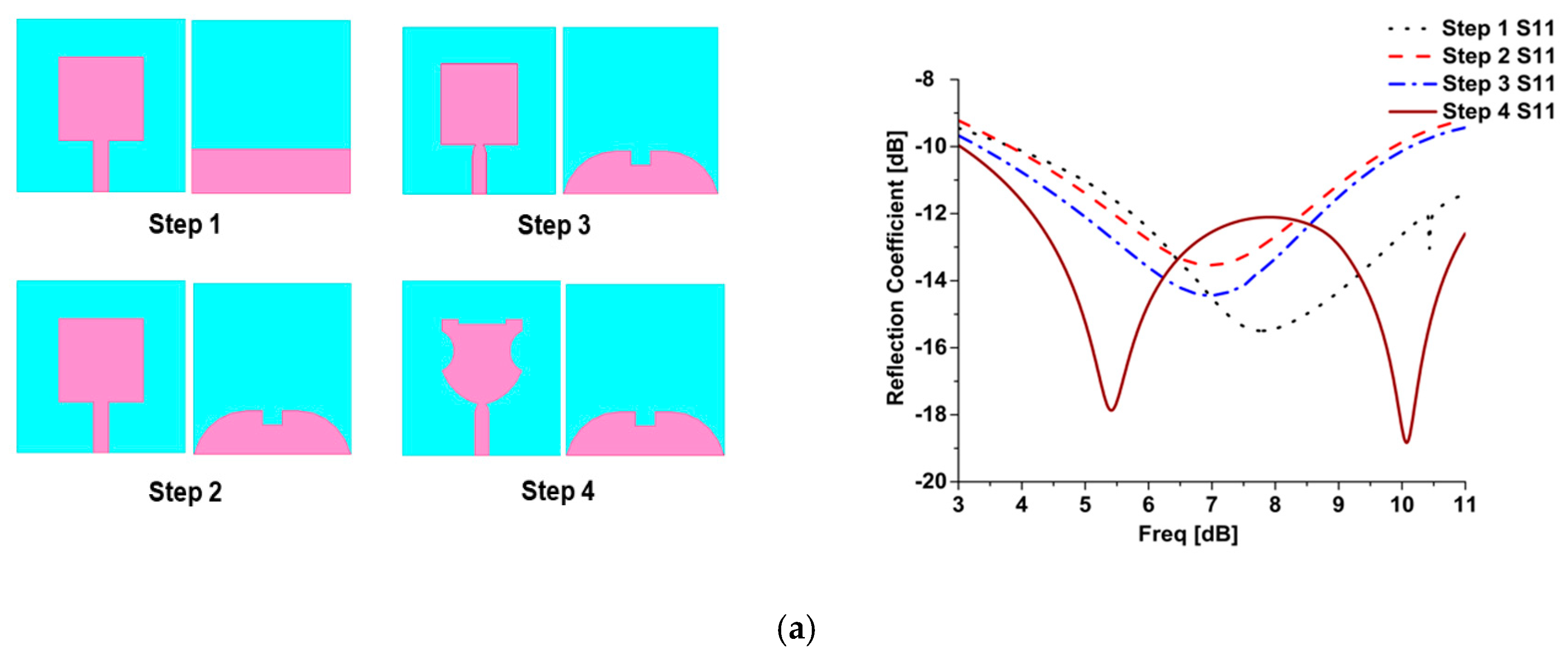
2.1. Single UWB Antenna Configuration

A low-cost 20 mm × 20 mm FR-4 substrate of thickness 1 mm, relative permittivity of 4.4 and dielectric loss tangent of 0.02 is used to design the single antenna. The antenna geometry has evolved from a conventional rectangular patch. The bottom corners of the radiator are chamfered, while semi-circles of radius 2.5 mm are subtracted from both sides of the patch. Rectangular slits are introduced at the top edge of each radiating patch. The resulting semi-elliptical shape provides good impedance matching in the band of interest. A microstrip feed line with chamfered top edge is used to excite antenna elements with matched impedance. All modification steps and their effect on the reflection coefficient is shown in Figure 1a.

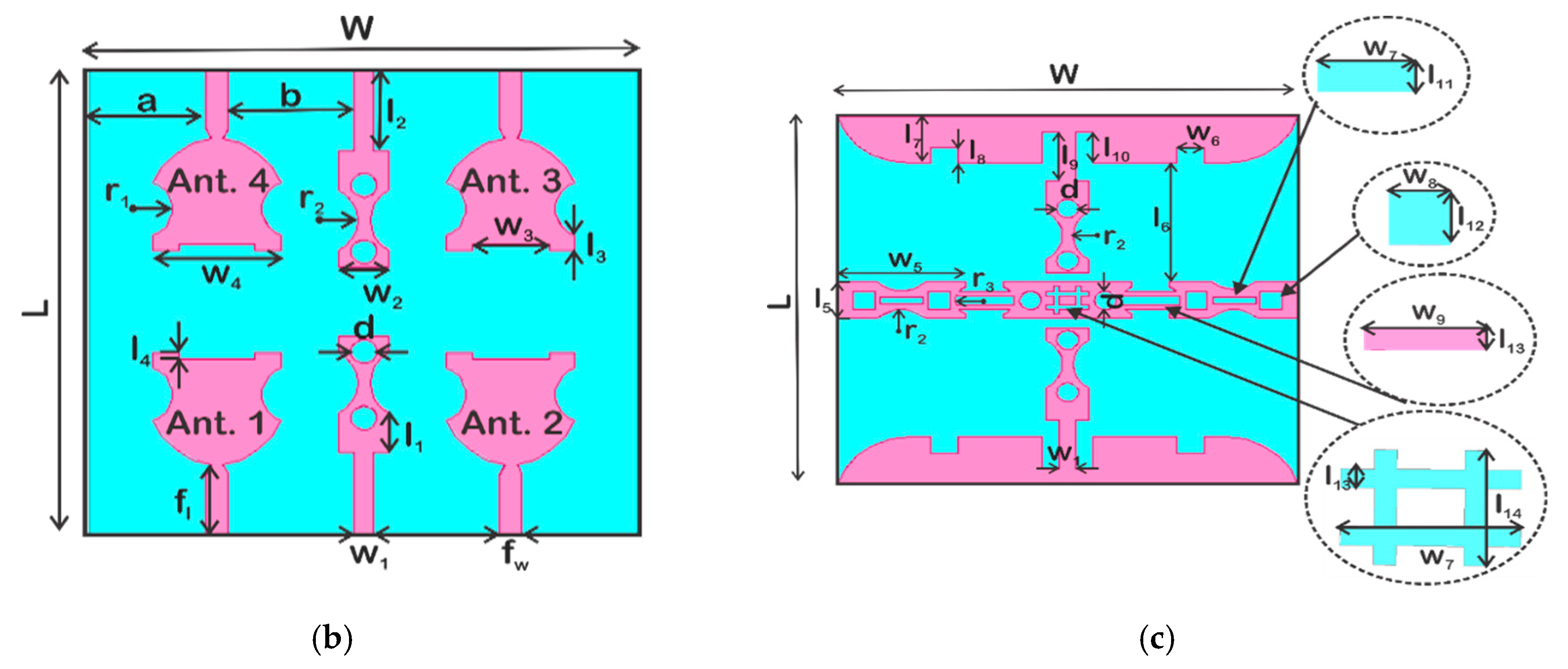
2.2. UWB-MIMO Antenna Configuration

The proposed MIMO antenna design has four identical radiating elements. Four antennas arranged in MIMO configuration are shown in Figure 1b. Rear view of the MIMO antenna is shown in Figure 1c. Partial ground plane with tapered top edges with certain defects have been introduced on the rear-side to achieve wide impedance bandwidth. The ground plane is defected with slits and stubs on the both sides. Antenna 1, 2 and 3, 4 are placed side-by-side whereas antenna 1, 4 and 2, 3 are in across configuration with respect to each other.

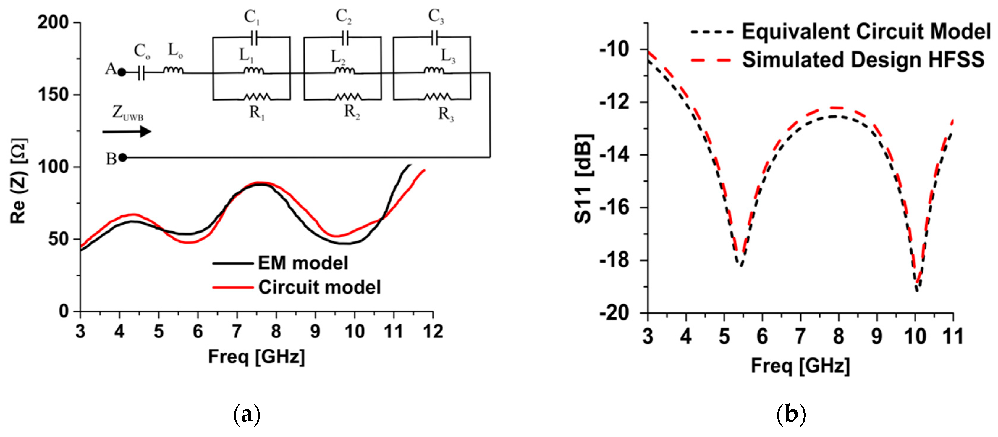
2.3. Equivalent Circuit Modeling

Circuit modeling of a UWB antenna is generally carried out in a time domain simulation because of extremely wide bandwidth. The modeling is carried out by matching the input impedance or admittance of the antenna with the lumped equivalent model. One way of modeling a UWB antenna is by considering it a combination of various overlapping adjacent resonators. If a parallel RLC resonator is considered as a unit element, a number of them is considered to be attached in series as shown in Figure 2a. Based on the required resonances, the number of these RLC resonant elements can be added or subtracted.
The values of these lumped components are optimized through a schematic solver where the values of each element is tuned to match the envelop of the impedance curve and resonance peaks. The proposed UWB antenna element comprises of three resonant peaks within the UWB band, one is around 3 GHz, second is around 7 GHz and third is around 11.5 GHz. Therefore, three parallel resonant circuits are included in the equivalent circuit model. The equivalent circuit lumped components optimized at R1 = 80 Ω, R2 = 95 Ω, R3 = 110 Ω, L1 = 1.4 nH, L2 = 0.4 nH, L3 = 0.21 nH, C1 = 1.92 pF, C2 = 1.25 pF and C3 = 0.82 pF.

3. Isolation Mechanisms

Two distinct techniques are employed to achieve isolation for side-by-side and across antenna arrangements. A horizontal parasitic decoupling strip is designed and placed in the middle of the rear-side for isolating antennas placed across and diagonally. Isolation among side-by-side antennas is achieved through a dumbbell shaped stub attached to the ground plane. The same structure is also produced on the top layer between antennas. The fabricated UWB-MIMO antenna design is shown in Figure 3.

3.1. Decoupling Structure for Side-by-Side Radiators

The dumbbell shaped stub attached to the ground plane provides isolation between side-by-side radiating elements. The circles are etched in the center of the dumbbell structure and semi-circles are subtracted from its sides in order to effectively introduce the desired capacitive and inductive loading of the ground plane. The decoupling structure is shown in Figure 1a. Replicas of these stubs are placed on the top side between antennas as well. These strips, on the top side, act as transmission line resonators and effectively reduce the mutual coupling between the side-by-side radiating elements. Decoupling performance better than 20 dB is achieved between side-by-side antennas.

3.2. Decoupling Structure for Across Radiators

The mutual coupling reduction between antennas placed across is achieved by a customized parasitic decoupling structure. The structure consists of several resonant features combined to form a horizontal strip placed in the middle of the substrate’s rear-side. The decoupling strip consists of three distinct sections which are joined together horizontally. Two circles and a hash sign slot are etched in the central section whereas squares and rectangular slots are etched in the outer section. These distinct structures combine to form a wide-band multi-resonant structure. It provides isolation better than 20 dB between antennas placed across. This customized structure is shown in Figure 1b.

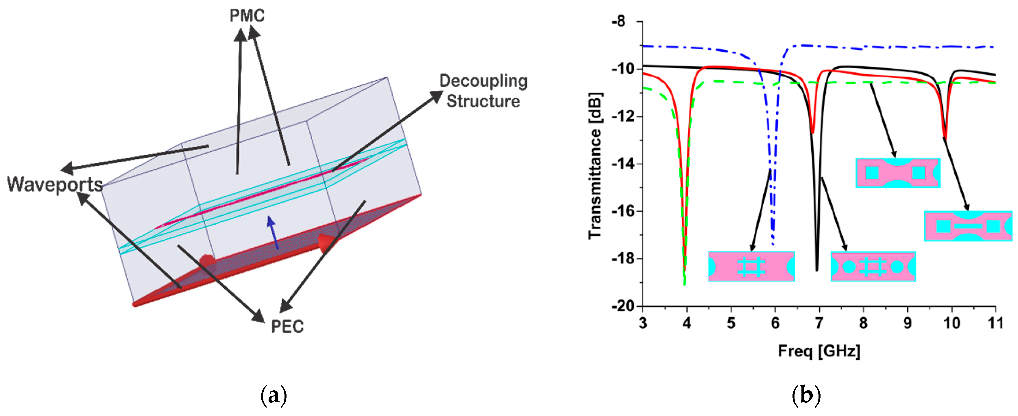
3.3. Analysis of Parasitic Decoupling Structure

The resonant frequency analysis of the parasitic decoupling structure is shown in Figure 4. It is performed by using wave ports in a full wave electromagnetic solver (Ansys HFSS®). The analysis setup and overall transmission loss over the UWB band is shown in Figure 4. Top and bottom side of an air box containing the resonant structure is excited with wave ports whereas the front and backside of the box is assigned perfect magnetic conductors. The other two sides (left and right) are assigned with the perfect electric conductor boundary conditions. It is apparent that different resonant components of the decoupling structure contribute in achieving the isolation between antennas placed across or diagonally. An overall isolation of 20 dB is provided by this parasitic structure.

4. Results and Discussions

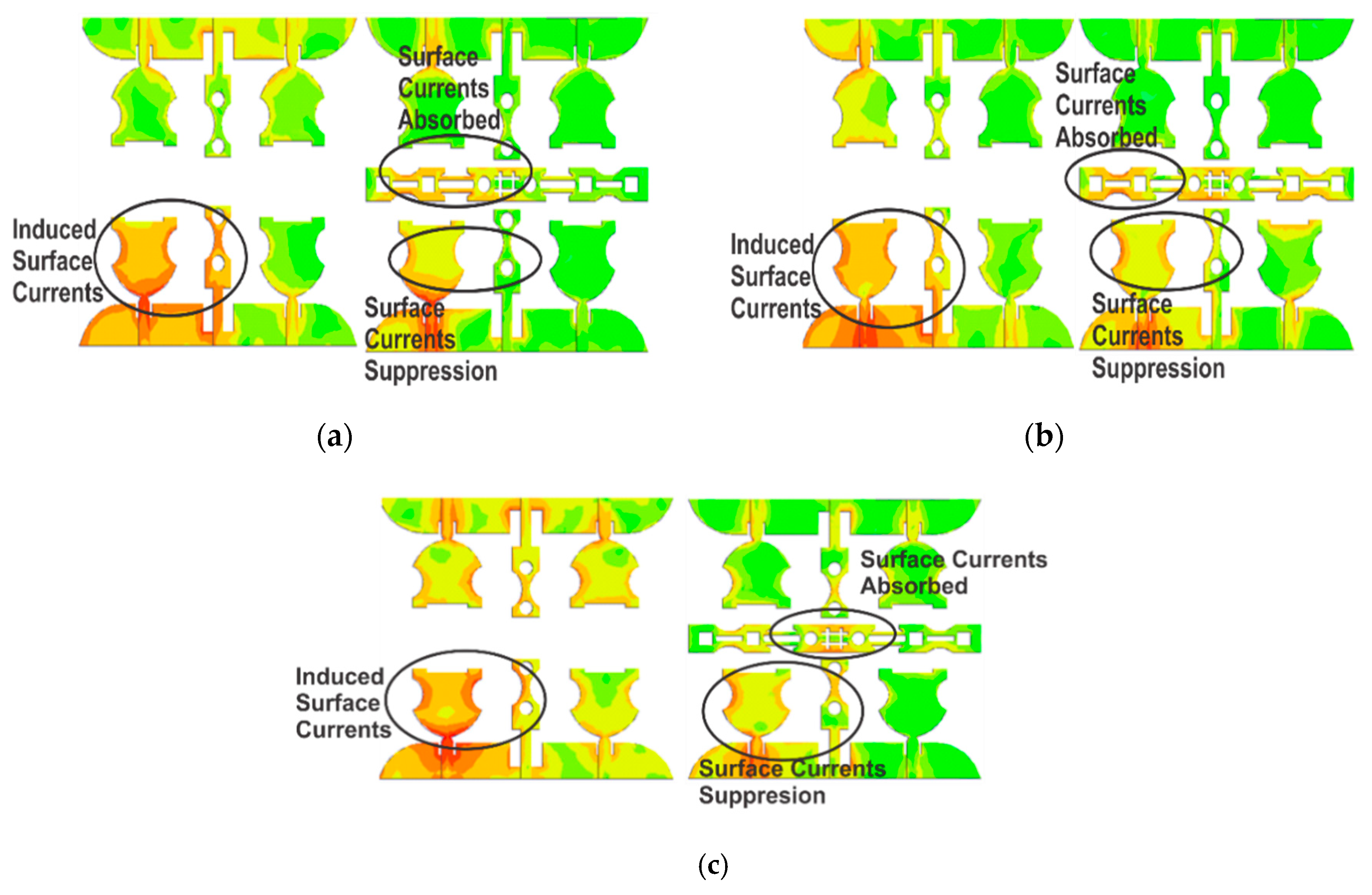
4.1. Induced Surface Currents

The surface currents at 4 GHz, 6 GHz and 10 GHz are shown in Figure 5. Only one antenna element is made to radiate and others are terminated at matched impedance in order to observe the effect of radiation. There are strong induced surface currents on the non-radiating elements which are caused by coupled fields. Both side and facing elements develop these induced currents. The introduction of decoupling structure helps in suppressing these coupling, in Figure 5a the current plot at 4 GHz is shown and it can be observed that the coupled currents are now visible on the outer section of the decoupling structure which means that these sections resonate at lower frequency which is supported by Figure 4b as well. Likewise the current plot at 6 GHz is shown in Figure 5b and the introduction of decoupling structure suppresses these currents. The middle section as well as side sections is responsible for this suppression. Finally Figure 5c displays the higher frequency current distribution at 10 GHz and the middle section of the decoupling structure in particular is responsible for this current suppression. It is also evident from Figure 4b.

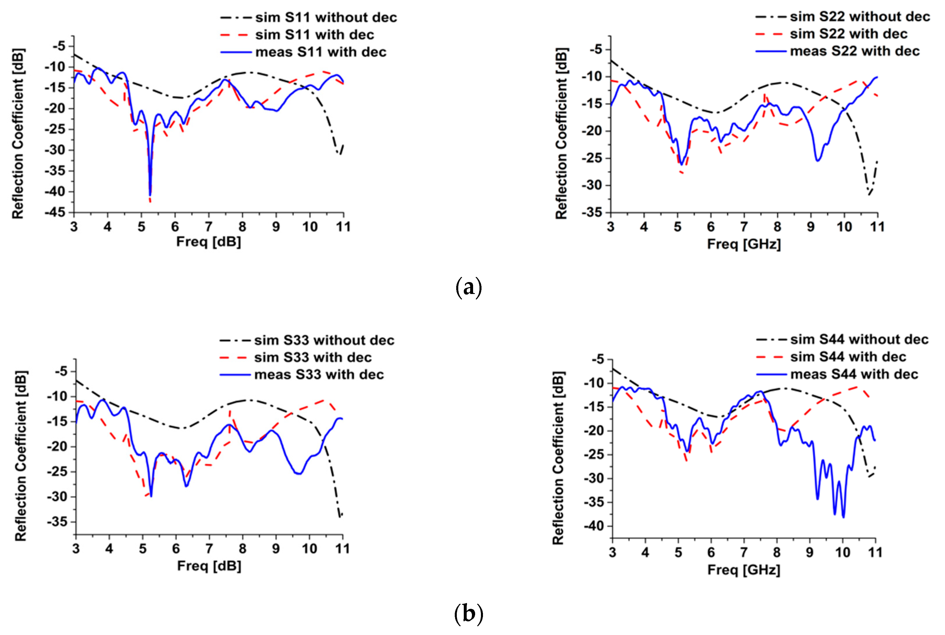
4.2. Impedance Matching

The impedance matching response with and without decoupling structures for antenna elements is shown in Figure 6. The modification in the patch design and partial ground plane helps in achieving impedance matching in the desired frequency band. The decoupling structures on the other hand also improve the impedance matching especially in the lower and upper band. The simulated and measured return loss results are both below 10 dB in the entire UWB frequency band.

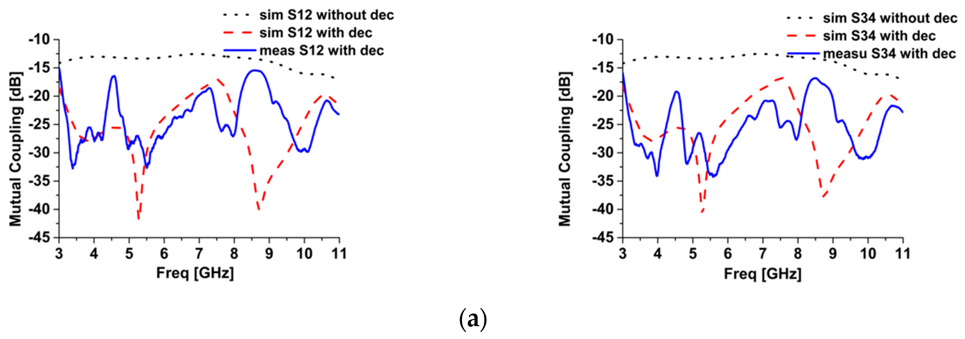
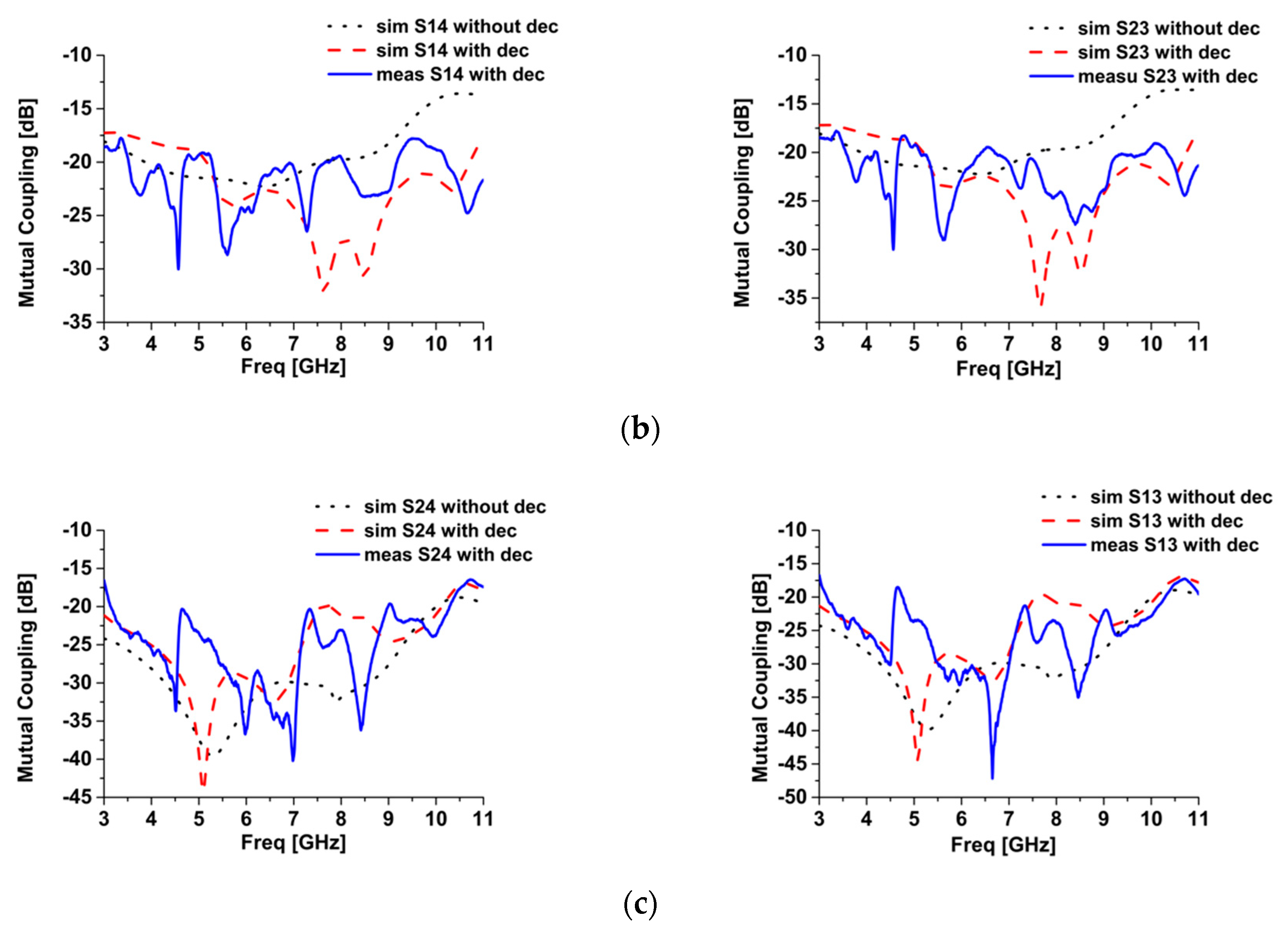
4.3. Isolation/Decoupling Performance

The simulated and measured isolation/decoupling performance for all relative placements are shown in Figure 7. Isolation better than 20 dB is achieved in the entire band for all configurations. Two distinct isolation mechanisms, stub loading in the ground plane as well as parasitic decoupling element provide significant mutual coupling reduction among antennas. Since the diagonally placed elements 1, 3 and 2, 4 are spatially apart so they have minimum coupling even without the use of decoupling structure. However, the strong coupling between antenna 1, 2 and 3, 4 are greatly suppressed by use of dumbbell shaped decoupling structure. The high frequency coupling in across elements 1, 4 and 2, 3 are reduced remarkably by employing the parasitic decoupling structure.

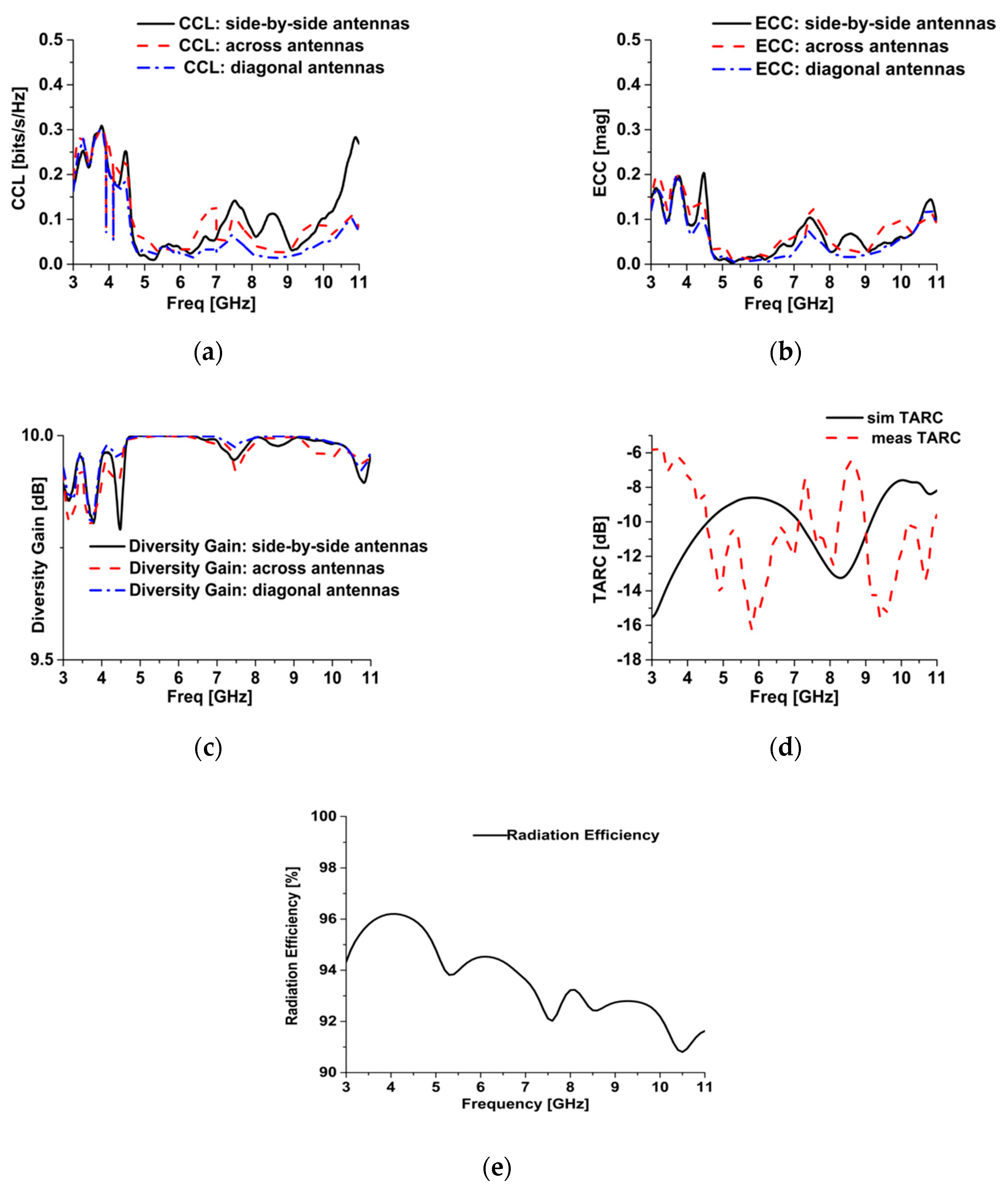
4.4. MIMO Performance Parameters

The diversity performance of MIMO antennas is evaluated through certain parameters like channel capacity loss (CCL), envelope correlation coefficient (ECC), diversity gain (DG) and total active reflection coefficient (TARC). For an acceptable MIMO performance CCL and ECC should be less than 0.5 whereas TARC should be below 0 dB [30]. ECC, DG and TARC are calculated using the relations given in [3]. ECC values can be approximated through scattering parameters instead of far field patterns. It gives an accurate estimate of the envelope correlation without 3D measurement of the radiation pattern. The relation is assumed for rich isotropic scattering environment and is given in Equation (1):
| S 11 * S 12 + S 21 * S 22 | 2 ( 1 ( | S 11 | 2 | S 21 | 2 ) ) ( 1 ( | S 22 | 2 | S 12 | 2 ) )
For MIMO systems, multiple antennas affect each other when actively involved in transmission or reception therefore they change the overall operating bandwidth and efficiency. TARC is a new metric that has been used to incorporate the overall combined effect of all antennas in a MIMO system and is calculated by using the Equation (2):
| S 11 + S 12 + S 13 + S 14 | 2 + | S 21 + S 22 + S 23 + S 24 | 2 + | S 31 + S 32 + S 33 + S 34 | 2 + | S 41 + S 42 + S 43 + S 44 | 2 4
Diversity gain is related to the calculated ECC value of the MIMO antenna system. The relation between ECC and DG is given by the Equation (3)
D G = 10 1 | E C C | 2
These parameters for the proposed MIMO antenna are shown in Figure 8. All the parameters have values within the suitable range for all the possible placement of four antennas. CCL is less than 0.3 whereas ECC is less than 0.2, thus ensuring the diversity performance of proposed MIMO antenna. TARC gives the overall match of the MIMO system with the value −8 dB. Other parameters like radiation efficiency and peak gain also highlight performance of the proposed antenna system. The radiation efficiency and peak gain of the proposed MIMO antenna is shown in Figure 8e and Figure 9, respectively. The antenna has reasonable gain values in the entire frequency band with the highest value of 4 dB. The proposed antenna has radiation efficiency above 90% in the complete frequency band thus making it an efficient radiation system.

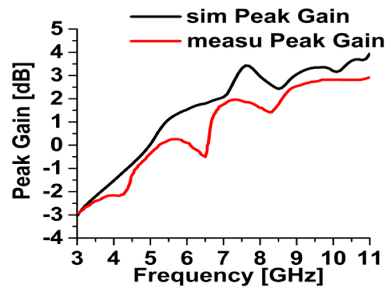
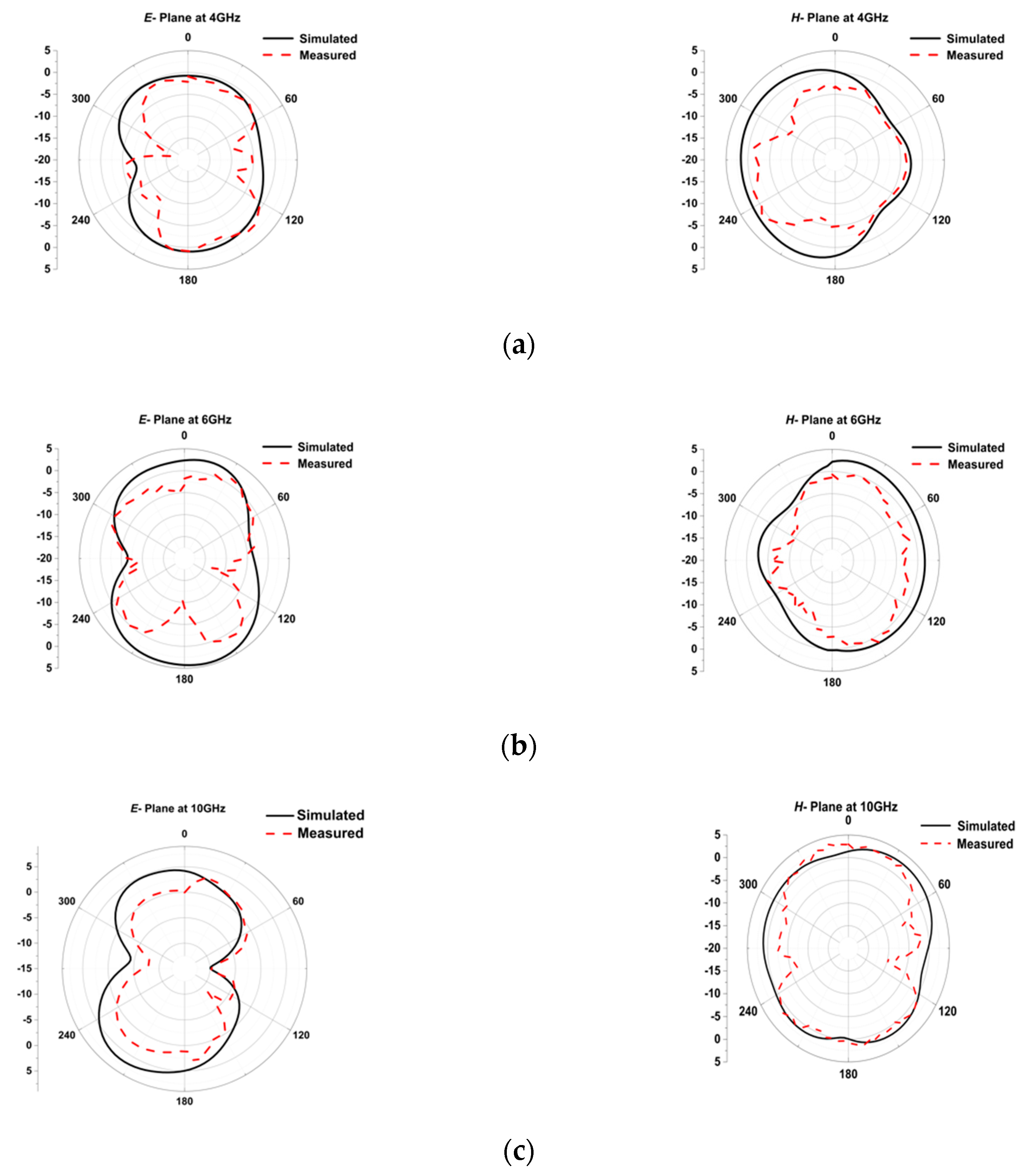
4.5. Radiation Characteristics

The normalized E and H plane radiation patterns taken from simulations and well as measurements at 4 GHz, 6 GHz and 10 GHz are shown in Figure 10. Both E- plane and H- plane patterns are omni-directional in nature and radiate in all directions as intended. Slight disagreement between measured and simulated patterns is observable because of the measurement setup constraints and fabrication tolerances. Overall the radiation envelope of measured and simulated patterns is similar which ensures the effective radiation behavior.

5. Comparison with the Existing Literature

The proposed MIMO system is designed for UWB applications. The existing literature reports several UWB-MIMO antennas. However, the proposed design is highly competitive to the reported designs in terms of isolation, size/profile and MIMO parameters. This MIMO antenna not only has a compact size but also exhibits efficient performance. A comprehensive comparison with the recent literature is shown in Table 1. The proposed work is compared with planar two-port and four-port reported designs. It has the smallest MIMO antenna dimensions of 40 × 43 × 1 mm3 and highest isolation of 20 dB in comparison with reported designs in Table 1. Moreover, proposed design has desirable values of ECC, CCL and TARC and the highest values of gain and efficiency in comparison, whereas most of the reported designs in the table are not evaluated in terms of CCL and TARC.

6. Conclusions

In this manuscript, a planar and compact quad-element MIMO antenna suitable for UWB applications is presented. The novel semi-elliptical radiating elements are realized on low-cost FR-4 substrate. Various design modifications in the patch itself and ground plane ensure the wideband impedance matching. Isolation level of at least 20 dB is achieved for the entire band owing to the two distinct isolation mechanisms of parasitic resonators and ground plane with reactive stub loading. Simulated and measured results of the proposed design are in good agreement. The diversity performance criteria indicate suitability of the proposed design for UWB-MIMO applications. The proposed antenna system is an excellent candidate for WPAN applications for consumer electronics.

Author Contributions

F.A. performed antenna designing and software simulation under the supervision of R.S. T.S., S.u.R., and M.B. managed the writing of the paper. M.F.S. provided fabrication, testing and measurement facilities.

Funding

This research received no external funding.

Conflicts of Interest

The authors declare no conflicts of interest.

References

  1. Roshna, T.K.; Deepak, U.; Sajitha, V.R.; Vasudevan, K.; Mohanan, P. A Compact UWB-MIMO Antenna with Reflector to Enhance Isolation. IEEE Trans. Antennas Propag. 2015, 63, 1873–1877. [Google Scholar] [CrossRef]
  2. Sipal, D.; Abegaonkar, M.P.; Koul, S.K. Easily Extendable Compact Planar UWB-MIMO Antenna Array. IEEE Antennas Wirel. Propag. Lett. 2017, 16, 2328–2331. [Google Scholar] [CrossRef]
  3. Chandel, R.; Gautam, A.K.; Rambabu, K. Tapered Fed Compact UWB-MIMO-Diversity Antenna with Dual Band-Notched Characteristics. IEEE Trans. Antennas Propag. 2018, 66, 1677–1684. [Google Scholar] [CrossRef]
  4. Nadeem, I.; Choi, D. Study on Mutual Coupling Reduction Technique for MIMO Antennas. IEEE Access 2019, 7, 563–586. [Google Scholar] [CrossRef]
  5. Iqbal, A.; Saraereh, O.A.; Ahmad, A.W.; Bashir, S. Mutual Coupling Reduction Using F-Shaped Stubs in UWB-MIMO Antenna. IEEE Access 2017, 6, 2755–2759. [Google Scholar] [CrossRef]
  6. Yin, Y.; Hong, J.; Luo, C.; Amin, M. A compact planar UWB-MIMO antenna using modified ground stub structure. IEICE Electron. Express 2017, 14, 20170883. [Google Scholar] [CrossRef]
  7. Ul Haq, M.A.; Koziel, S. Ground Plane Alterations for Design of High-Isolation Compact Wideband MIMO Antenna. IEEE Access 2018, 6, 48978–48983. [Google Scholar] [CrossRef]
  8. Zhang, S.; Pedersen, G.F. Mutual coupling reduction for UWB-MIMO antennas with a wideband neutralization line. IEEE Antennas Wirel. Propag. Lett. 2016, 15, 166–169. [Google Scholar] [CrossRef]
  9. Hassan, T.; Khan, M.U.; Attia, H.; Sharawi, M.S. An FSS Based Correlation Reduction Technique for MIMO Antennas. IEEE Trans. Antennas Propag. 2018, 66, 4900–4905. [Google Scholar] [CrossRef]
  10. Qamar, Z.; Riaz, L.; Chongcheawchamnan, M.; Khan, S.A.; Shafique, M.F. Slot combined complementary split ring resonators for mutual coupling suppression in microstrip phased arrays. IET Microw. Antennas Propag. 2014, 8, 1261–1267. [Google Scholar] [CrossRef]
  11. Wu, D.W.; Cheunng, S.W.; Li, Q.L.; Yuk, T.I. Decoupling using diamond shaped patterned ground resonator for small MIMO antennas. IET Microw. Antennas Propag. 2017, 11, 177–183. [Google Scholar] [CrossRef]
  12. Ghosh, T.; Ghosal, S.; Mitra, D.; Chaudhuri, S.R.B. Mutual Coupling Reduction Between Closely Placed Microstrip Patch Antenna Using Meander Line Resonator. Prog. Electromagn. Res. Lett. 2016, 59, 115–122. [Google Scholar] [CrossRef]
  13. Gogosh, N.; Shafique, M.F.; Saleem, R.; Usman, I.; Faiz, A.M. An UWB diversity antenna array with a novel H type decoupling structure. Microw. Opt. Technol. Lett. 2013, 55, 2715–2720. [Google Scholar] [CrossRef]
  14. Srivastava, G.; Mohan, A. Compact MIMO Slot Antenna for UWB Applications. IEEE Antennas Wirel. Propag. Lett. 2016, 15, 1057–1060. [Google Scholar] [CrossRef]
  15. Tang, Z.; Wu, X.; Zhan, J.; Hu, S.; Xi, Z.; Liu, Y. Compact UWB-MIMO Antenna with High Isolation and Triple Band-Notched Characteristics. IEEE Access 2019, 7, 19856–19865. [Google Scholar] [CrossRef]
  16. Tao, J.; Feng, Q. Compact Ultrawideband MIMO Antenna with Half- Slot Structure. IEEE Antennas Wirel. Propag. Lett. 2017, 16, 792–795. [Google Scholar] [CrossRef]
  17. Yadav, D.; Abegaonkar, M.P.; Koul, S.K.; Tiwari, V.N.; Bhatnagar, D. Two Element Band-Notched UWB-MIMO Antenna with High and Uniform Isolation. Prog. Electromagn. Res. 2018, 63, 119–129. [Google Scholar] [CrossRef]
  18. Mathur, R.; Dwari, S. Compact 4-Port MIMO/diversity antenna with low correlation for UWB application. Frequenz. 2018, 72, 429–435. [Google Scholar] [CrossRef]
  19. Wu, W.; Yuan, B.; Wu, A. A Quad-Element UWB-MIMO Antenna with Band-Notch and Reduced Mutual Coupling Based on EBG Structures. Int. J. Antennas Propag. 2018, 2018, 8490740. [Google Scholar] [CrossRef]
  20. Anitha, R.; Vinesh, P.V.; Prakash, K.C.; Mohanan, P.; Vasudevan, K. A compact quad element slotted ground wideband antenna for MIMO applications. IEEE Trans. Antennas Propag. 2016, 64, 4550–4553. [Google Scholar] [CrossRef]
  21. Ibrahim, A.A.; Abdalla, M.A.; Hu, Z. Design of a compact MIMO antenna with asymmetric coplanar strip-fed for UWB applications. Microw. Opt. Technol. Lett. 2017, 59, 31–36. [Google Scholar] [CrossRef]
  22. Hu, H.; Chen, F.; Chu, Q. A Wideband U-Shaped Slot Antenna and Its Application MIMO Terminals. IEEE Antennas Wirel. Propag. Lett. 2016, 15, 508–511. [Google Scholar] [CrossRef]
  23. Kang, L.; Li, H.; Wang, X.; Shi, X. Compact Offset Microstrip-Fed MIMO Antenna for Band-Notched UWB Applications. IEEE Antennas Wirel. Propag. Lett. 2015, 14, 1754–1757. [Google Scholar] [CrossRef]
  24. Choi, J.; Hwang, W.; You, C.; Jung, B.; Hong, W. Four-Element Reconfigurable Coupled Loop MIMO Antenna Featuring LTE Full-Band Operation for Metallic-Rimmed Smartphone. IEEE Trans. Antennas Propag. 2019, 67, 99–107. [Google Scholar] [CrossRef]
  25. Hussain, R.; Sharawi, M.S.; Shamim, A. An Integrated Four-Element Slot-Based MIMO and a UWB Sensing Antenna System for CR Platforms. IEEE Trans. Antennas Propag. 2018, 66, 978–983. [Google Scholar] [CrossRef]
  26. Malviya, L.; Panigrahi, R.; Kartikeyan, M.V. Four Element Planar MIMO Antenna Design for Long-Term Evolution Operation. IETE J. Res. 2018, 64, 367–373. [Google Scholar] [CrossRef]
  27. Ibrahim, A.A.; Machac, J.; Shubair, R.M. Compact UWB-MIMO antenna with pattern diversity and band rejection characteristics. Microw. Opt. Technol. Lett. 2017, 59, 1460–1464. [Google Scholar] [CrossRef]
  28. Khan, M.S.; Capobianco, A.D.; Asif, S.; Iftikhar, A.; Ijaz, B.; Braaten, B.D. Compact 4 × 4 UWB-MIMO antenna with WLAN band rejected operation. Electron. Lett. 2015, 51, 1048–1050. [Google Scholar] [CrossRef]
  29. Zhu, J.; Li, S.; Feng, B.; Deng, L.; Yin, S. Compact dual-polarized UWB quasi-self-complementary MIMO/diversity antenna with band-rejection capability. IEEE Antennas Wirel. Propag. Lett. 2016, 15, 905–908. [Google Scholar] [CrossRef]
  30. Jafri, S.I.; Saleem, R.; Shafique, M.F.; Brown, A.K. Compact reconfigurable multiple-input-multiple-output antenna for ultra-wideband applications. IET Microw. Antennas Propag. 2016, 10, 413–419. [Google Scholar] [CrossRef]
Figure 1. UWB-MIMO antenna design:(a) single antenna element evolution (b) front view of final design; (c) rear view of final design; L = 40,W = 43, fl = 6, fw = 1.8, l1 = 3, w1 = 1.5,l2 = 7, w2 = 4, l3 = 1.3, w3 = 6, l4 = 0.6, w4 = 10, l5 = 4, w5 = 12, l6 = 13, w6 = 2.6, l7 = 5.1, l8 = 1.7, l9 = 5.3, l10 = 3.4, l11 = 0.8, w7 = 4, l12 = 2,w8 = 2, l13 = 0.5, w9 = 5.5, l14 = 3, d = 2, r1 = 2.5, r2 = 3, r3 = 1.5, a = 9.1, b = 9.8 (all dimensions are in mm).
Applsci 09 02371 g001aApplsci 09 02371 g001b
Figure 2. Equivalent circuit: (a) real impedance of UWB antenna; (b) comparison of reflection coefficients.
Applsci 09 02371 g002
Figure 3. Fabricated UWB-MIMO antenna: (a) front view; (b) rear view.
Applsci 09 02371 g003
Figure 4. Analysis. (a) Analysis setup; (b) transmission loss.
Applsci 09 02371 g004
Figure 5. Surface current distribution of UWB-MIMO antenna: (a) 4 GHz; (b) 6 GHz; (c) 10 GHz.
Applsci 09 02371 g005
Figure 6. Simulated and Measured reflection coefficient (a) antenna 1 and 2; (b) antenna 1 and 3.
Applsci 09 02371 g006
Figure 7. Mutual coupling reduction among antenna elements: (a) side-by-side antennas; (b) across antennas; (c) diagonally-across antennas.
Applsci 09 02371 g007aApplsci 09 02371 g007b
Figure 8. MIMO performance parameters: (a) CCL; (b) ECC; (c) DG; (d) TARC; (e) radiation efficiency.
Applsci 09 02371 g008
Figure 9. Simulated and measured peak gain.
Applsci 09 02371 g009
Figure 10. E and H plane radiation patterns: (a) 4 GHz; (b) 6 GHz; (c) 10 GHz.
Applsci 09 02371 g010
Table 1. Comparison with the existing literature.
Ref. NoGeometryPortsSize (mm3)Isolation (dB)TARCECCCCLPeak GainEfficiency (%)Frequency Band (GHz)
[18]Planar436 × 36 × 1.615-<0.5-2.5–4703.1–10.6
[19]Planar460 × 60 × 1.617.5-<0.3<0.4891.23–16.2
[20]Planar445 × 45 ×1.614-<0.25-4912.2–3.8/2.3–5.7/2.4, 5.1–5.8
[21]Planar226 × 60 × 1.615-<0.01-3.5803.1–10.6
[22]Planar266 × 52 × 1.515-<0.02-1.8–466Lower UWB band
[23]Planar238.5 × 38.5 × 1.615-<0.02-1.4–3.6753.1–10.6
[24]Planar270 × 150 × 1>10.5-<0.5/<0.1--40/800.699–0.960/1.710–2.690
[25]Planar4120 × 60 × 1.513−10<0.248-3.2751.77–2.51
[26]Planar468 × 98 × 1.510-<0.1-2.73711.66–2.7
[27]Planar250 × 28 × 1.618-<0.12<0.4--3.1–10.6
[28]Planar450 × 39.8 × 1.52417---2.5–6-2.7–5.1/5.9–12
[29]Planar450 × 50 × 120-<0.3---3.1–10.6
This workPlanar440 × 43 ×120−8<0.2<0.34923.1–10.6

