Article

User-Aware Audio Marker Using Low Frequency Ultrasonic Object Detection and Communication for Augmented Reality

1
School of Electrical Engineering and Computer Science, Gwangju Institute of Science and Technology, Gwangju 61005, Korea
2
Future Infrastructure Research Center, Korea Institute of Civil Engineering and Building Technology, Goyang-si, Gyeonggi-do 10223, Korea
3
Department of Electrical and Computer Engineering, City University of New York (CUNY), New York, NY 10017, USA
*
Author to whom correspondence should be addressed.
Appl. Sci. 2019, 9(10), 2004; https://doi.org/10.3390/app9102004
Submission received: 1 May 2019 / Revised: 11 May 2019 / Accepted: 13 May 2019 / Published: 16 May 2019
(This article belongs to the Special Issue Augmented Reality: Current Trends, Challenges and Prospects)

Abstract

:
In augmented reality (AR), audio markers can be alternatives to image markers for rendering virtual objects when an AR device camera fails to identify the image marker due to lighting conditions and/or the distance between the marker and device. However, conventional audio markers simply broadcast a rendering queue to anonymous devices, making it difficult to provide specific virtual objects of interest to the user. To overcome this limitation without relying on camera-based sensing, we propose a user-aware audio marker system using low frequency ultrasonic signal processing. The proposed system detects users who stay within the marker using ultrasonic-based object detection, and then it uses ultrasonic communication based on windowed differential phase shift keying modulation in order to send a rendering queue only to those users near the marker. Since the proposed system uses commercial microphones and speakers, conventional telecommunication systems can be employed to deliver the audio markers. The performance of the proposed audio marker system is evaluated in terms of object detection accuracy and communication robustness. First, the object detection accuracy of the proposed system is compared with that of a pyroelectric infrared (PIR) sensor-based system in indoor environments, and it is shown that the proposed system achieves a lower equal error rate than the PIR sensor-based system. Next, the successful transmission rate of the proposed system is measured for various distances and azimuths under noisy conditions, and it is also shown that the proposed audio marker system can successfully operate up to approximately 4 m without any transmission errors, even with 70 dBSPL ambient noise.

Graphical Abstract

1. Introduction

Augmented reality (AR) is usually described as the interaction between a real environment and computer-generated virtual objects through allowing users to interact with the virtual objects through visual, auditory, or haptic sensory modalities [1,2]. Distinct visual cues, such as image markers [1,2,3,4] or parts of the human body [5], are commonly used to place virtual objects into the real world. Among the various AR services, there are indoor guidance services widely used in public places such as museums and airports [1,2,3]. In order for this service to provide a user with a successful user experience, an AR marker in the indoor environment should be able to give information to the user at a relatively long distance in real time. It is also necessary to consider this situation as there may be several people who have different interests within the same space. For indoor guidance purposes, an AR marker, which is an image marker based on a combination of coloring patterns and quick response (QR) codes, was used for indoor AR services, because the detection and recognition mechanism in this method was robust with commercial mobile hardware, even at a long distance [3]. In particular, this marker was used for establishing indoor guidance systems for the visually impaired [3]. However, if such image markers were concentrated in a small area, many of the markers that were not interested in the view of the AR user might be observed, which caused an interference with the user’s immersive experience. Although inpainting techniques have been proposed to remove image markers from the user’s sight [4], the computational burden could be somewhat heavy for most mobile AR devices, limiting its applications [4]. Other visual marker approaches have been proposed as alternatives to image marker-based approaches. For example, the shape of human fingertips was utilized to replace an image marker as the role of visual cues in an AR device [5]. In other words, each fingertip acted as a virtual marker to interact with virtual objects at close distances. Despite its usefulness for some AR applications, this approach could be considerably distracting under visual conditions affected by illumination or occlusion [6,7,8]. While recent AR applications tried to recognize visual environments without using a marker, in order to deploy virtual objects in natural ways [9], such attempts required substantial computations of the AR device; thus, their use was limited to a certain AR scenario [10]. Visual marker limitations could also be avoided by using other marker types, such as gyroscope and global positioning system (GPS) sensors [11,12], but unfortunately, such markers were difficult to establish in indoor environments [11]. For example, while motion detection sensors, e.g., pyroelectric infrared (PIR) sensors, could work as indoor markers for some AR applications [13], PIR sensors failed to send rich information regarding virtual objects or events to the AR device.
Instead, our previous work proposed an audio marker based on low frequency ultrasound (LFU) [14]. There were many benefits to this approach. Since the frequency response of the LFU-based audio marker ranged from 18 to 20 kHz, the transmitted signal was inaudible to human ears, and its transceivers could be made of the most commercial off-the-shelf (COTS) loudspeakers and microphones [15]. Thus, operating the LFU-based audio marker did not require any additional hardware other than a generic device equipped with an audio interface, e.g., a smart phone. Therefore, the LFU-based audio marker could be useful for some AR service scenarios where conventional image markers were difficult. For example, audio markers could present virtual objects to the user although the user might not see an image marker. This was because the LFU spread across all directions within the room, regardless of the user’s visual focus or line-of-sight with the marker. However, the conventional LFU-based audio marker in [14] simply broadcast a rendering queue to anonymous devices inside the room, making it difficult to provide specific virtual objects of interest to a given user. Thus, an object detection method from the reflected LFU signal is required to provide user-awareness on the LFU-based AR marker, in order to overcome this limitation without relying on other types of additional sensors such as cameras [16] or PIR sensors [17].
Therefore, we propose a user-aware audio marker system using low frequency ultrasonic signal processing. Figure 1 shows an example application of a docent service in a museum. The proposed audio marker system only sends LFU signals to users detected in advance as being close to the object of interest, and thus it becomes suitable for a number of indoor AR applications.
The proposed audio marker system consists of an object detection module using received LFU images as well as an LFU communication module providing the audio marker. For the LFU-based object detection, a COTS speaker repeatedly plays a low frequency pulsed ultrasonic chirp signal, and a COTS microphone simultaneously records audio including ambient and chirp signals around the audio marker. The signal will be reflected back to the marker when an object physically blocks the chirp signal propagation, which results in amplifying the LFU frequency band with a distinct pattern. Therefore, the anomaly in the reflected signal, resulting from the object’s presence, can be detected by a time-frequency analysis. In other words, the reflected ultrasound is converted into a time-frequency representation, and then a background subtraction algorithm [18] is applied to segregate reflected chirp spectral components from the ambient audio. After that, the object presence or absence is then determined based on the likelihood ratio calculated from a priori and posteriori signal-to-noise ratios (SNRs) among the LFU and ambient noise. Next, the proposed audio marker operation switches from object detection to LFU communication when the object is considered to be in front of the proposed audio marker. Here, the LFU communication broadcasts a binary text message embedded in the audio marker. In detail, the binary text message is broadcast near the audio marker using a differential phase shift keying (DPSK) scheme, and consequently an AR device capable of demodulating DPSK can correctly receive the message when located near the audio marker. While the conventional audio marker system in [14] broadcasts the marker information to all the users inside the room, the proposed audio marker system first only utilizes low-frequency ultrasound to recognize users around the marker, and then sends the marker information to the detected user. In particular, when the visual sight is considerably distracted by ill-visual conditions affected by illumination or occlusion, the conventional image-based or location-based markers suffer greatly; however, the proposed system can still generate virtual objects and an environmental effect.
The remainder of this paper is organized as follows. Section 2 reviews the conventional LFU communication-based audio marker system [14,15], after which Section 3 proposes a user-aware audio marker system based on object detection using reflected LFU images and LFU communication for sending audio maker information. Section 4 evaluates the objective performance of the proposed audio marker system in terms of object detection accuracy and communication robustness. In addition, a comparison of the proposed system with other positioning systems for AR applications is given. Finally, Section 5 summarizes and concludes this paper.

2. Review of Low Frequency Ultrasonic Communication-based Audio Markers

Figure 2 shows a block diagram of a conventional LFU communication-based audio marker system [14]. As shown in the figure, a binary text data message as an audio marker is encoded in the audio marker transmitter using a forward error correction (FEC) coding algorithm, followed by DPSK modulation and gain normalization. In the audio marker receiver, the received signal is processed by gain normalization, DPSK demodulation, and FEC decoding.

2.1. Audio Marker Transmitter

The LFU communication-based audio marker transmitter sends an audio marker of a short text m in binary format though the LFU wave with three processing steps: FEC encoding, DPSK modulation, and gain normalization. First, the P binary bits to be transmitted at the i-th symbol are grouped as b i = [ b i 1 b i p b i P ] , where P = 24 in this paper. Next, b i is then encoded by an FEC algorithm [19]; thus, additional error correction bits are attached. In particular, a perfect binary Golay code, G 23 , is used for FEC encoding [19], i.e., b i is reshaped into an O × 12 matrix, and it is encoded by the (23,12) Golay block. Consequently, an O × 23 encoded block for the i-th symbol, b ˜ i , is generated. Note here that O = 2 and the coding rate of G 23 , R c = 52.17 % in this paper.
After FEC encoding, each encoded bit of b ˜ i is modulated by DPSK. In other words, b ˜ i is reshaped into a 1 × 46 vector, b ˜ i = [ b ˜ i 1 b ˜ i q b ˜ i Q ] , where Q = 46 in this paper. Then, differential encoding is applied to b ˜ i q , as in [15]:
d i q = b ˜ i q d i 1 q
where d i q is the q-th differentially encoded bit at the i-th symbol, and indicates the bitwise exclusive or (XOR) operation. After that, d i q is modulated with a sinusoidal signal by the windowed DPSK, so that:
c i ( n + q T b ) = w ( n ) cos ( 2 π f c n f s + π ( 1 d i q ) ) , n = 1 , 2 , , T b
In Equation (2), T b is the symbol length and is set to 96 because this is known as being the optimum by taking into account both the data transmission rate and communication robustness in noisy environments [15]. Moreover, f c and f s are a carrier frequency and a sampling frequency of the modulated signal, respectively. Here, f s is set to 48 kHz to support the frequency range of most COTS microphones and speakers. Accordingly, f c can be set from 18 to 20 kHz; it is set to 20 kHz in this paper. In addition, w ( n ) is a squared Hanning window, which can smooth the discontinuity between subsequent symbols to avoid unwanted impulsive noise in the modulated signals.
Next, the modulated signal in Equation (2), c i ( n + q T b ) , is subsequently normalized by its gain, so that:
s i T b ( n + q T b ) = G c i ( n + q T b ) 1 T b n = 1 T b | c i ( n + q T b ) |
where G = 2 14 is a normalization scale that corresponds to a half maximum sample value for a 16-bit resolution. Finally, the modulated LFU signal for the i-th symbol for all q, s i T b ( n ) , is transformed into an analogue signal by a digital-to-analogue converter (DAC), and then it spreads through the aerial medium.

2.2. Audio Marker Receiver

In the audio marker receiver, the input signal recorded by the COTS microphone, y i ( n ) , is the superposition of s i T b ( n ) in (3) and the additive environmental noise, z i ( n ) , so that:
y i ( n ) = h ( n ) s i T b ( n ) + z i ( n )
where h ( n ) is the impulse response of the propagation channel from the LFU transmitter to the receiver. As shown in the lower part of Figure 2, the carrier frequency bandpass filter (BPF), g ( n ) , is then applied to y i ( n ) to estimate s i T b ( n + q T b ) , so that:
s ^ i ( n + q T b ) = y i ( n + q T b ) g ( n + q T b ) .
By assuming that z i ( n ) rarely overlaps with s i T b ( n ) at the carrier frequency band [20], z i ( n ) contained in y i ( n ) (see Equation (4)) is filtered out. Similar to Equation (3), the filtered receiver signal corresponding to the q-th bit, s ^ i ( n + q T b ) , is normalized by its gain to compensate for energy loss resulting from the frequency-selective characteristics of h ( n ) , so that:
c ^ i ( n + q T b ) = G s ^ i ( n + q T b ) 1 T b n = 1 T b | s ^ i ( n + q T b ) |
where c ^ i ( n + q T b ) is an estimate of b ˜ i q at the i-th symbol, and also G = 2 14 .
Finally, DPSK demodulation is applied using non-coherent detection [20], so that:
b ˜ ¯ i q = { 1 , i f n = 1 T b c ^ i ( n + q T b ) c ^ i 1 ( n + q T b ) > 0 0 , o t h e r w i s e
and the received audio marker for the p-th binary bit at the i-th symbol, b ^ i p , is obtained by applying the FEC decoding with G 23 on b ˜ ¯ i q [19].

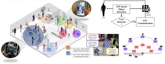
3. Proposed User-Aware Audio Marker System Using Low Frequency Ultrasonic-based Object Detection and Communication

The proposed user-aware audio marker system comprises LFU-based object detection and LFU communication, as shown in Figure 3. The proposed system consistently senses a user’s existence around the marker’s location. Consequently, when a user is detected by an LFU-based object detection algorithm, the proposed system sends the marker’s information to the detected user using LFU communication. The following subsections describe the details of the LFU-based object detection and LFU communication for the proposed system.

3.1. LFU-Based Object Detection

Figure 4 shows a block diagram of the LFU-based object detection method using LFU images. A speaker periodically produces a low frequency pulsed ultrasound from 18 to 20 kHz. In this paper, a linear frequency modulated (LFM) chirp is utilized [21], where the chirp length and repetition time are set to 512 and 4096 samples at a sampling rate of 48 kHz, respectively. While periodically reproducing the low frequency pulsed ultrasound, a microphone simultaneously captures the chirps and ambient sound, which are then filtered with a matched filter to clarify the pulsed LFU. Next, the filtered signal is segmented into consecutive frames of 4096 samples. Then, a Hanning window of a length of 256 samples, with a 50% overlap, is applied to each frame, which produces 31 sub-frames for a frame. Finally, a 256-point short-time Fourier transform (STFT) is applied to each sub-frame to obtain a spectrogram image.
Let I ( p , n ) be a spectrogram image at a pixel p and a sub-frame n . Each input spectrogram image is subtracted by the background image, so that:
F ^ 2 ( p , n ) = I 2 ( p , n ) B ^ 2 ( p ) ,   n = 1 , 2 , , 31
where B ^ ( p ) is the initial background image estimated by assuming that there is no object within the initial N ( = 31 ) sub-frames [22], so that:
B ^ ( p ) = 1 N n = 0 N 1 I ( p , n )
Next, Equation (8) can be written in the product form of:
F ^ 2 ( p , n ) = H 2 ( p , n ) I 2 ( p , n )
where H ( p , n ) is a suppression function [23], defined as:
H ( p , n ) = 1 B ^ 2 ( p ) I 2 ( p , n ) = γ ( p , n ) 1 γ ( p , n )
Note here that 0 H ( p , n ) 1 [23], and γ ( p , n ) = I 2 ( p , n ) / B ^ 2 ( p ) is the a posteriori SNR.
When an object is absent (hypothesis H 0 ), spectrogram images include only the background, i.e., H 0 : I ( p , n ) = B ( p ) ; on the other hand, when an object is present (hypothesis H 1 ), spectrogram images include the foreground and background, i.e., H 1 : I ( p , n ) = F ( p , n ) + B ( p ) . The likelihood ratio for a pixel point p and n-th sub-frame can be expressed as [23]:
Λ ( p , n ) = 1 1 + ξ ( p , n ) exp ( γ ( p , n ) ξ ( p , n ) 1 + ξ ( p , n ) )
where ξ ( p , n ) = F ^ 2 ( p , n ) / B ^ 2 ( p ) is the a priori SNR. The decision rule is established from the log likelihood ratio [23], so that:
log Λ ( n ) = p B log Λ ( p , n ) > H 1 < H 0 η
where B implies the area in which a low frequency ultrasound can be reached. In particular, when an object is detected, log Λ ( n ) is also used to scale the LFU transmission signal, which will be explained in the next subsection. Otherwise, the background images are updated as:
B ^ ( p ) = α B ^ ( p ) + ( 1 α ) I ( p , n )
where α is set to 0.7 through exhaustive experiments.

3.2. LFU Communication for Audio Marker Transmission

Shortly after a user is detected by the object detection method described in the previous subsection, the audio marker information can be sent to the detected user by using LFU communication, as described in Section 2.1. However, there is a significant difference between the conventional (Section 2.1) and proposed audio markers. In the proposed audio marker, the transmission power is controlled depending on the signal strength between the detected user and marker. In other words, the modulated signal for the q-th bit at the i-th symbol, c i ( n + q T b ) , is normalized by using its gain and log likelihood from Equation (13), rather than by using Equation (3). That is,
s ^ i T b ( n + q T b ) = β log Λ ( n ) G c i ( n + q T b ) 1 T b n = 1 T b | c i ( n + q T b ) |
where β is a constant that controls the transmission power with an inverse of log Λ ( n ) , and it is set to 0.05 according to preliminary experiments in the indoor environment. Owing to the adaptive scaling of the transmission signal, as described in Equation (15), the proposed audio marker can only send the marker’s information to the proximity of the detected user. Finally, for all q in Equation (15), s ^ i T b ( n + q T b ) is transformed into an analogue signal by a DAC and then sent to the AR device belonging to the detected user.

4. Performance Evaluation and Discussion

Since the proposed audio marker system was composed of two parts, its performance was evaluated by (1) an LFU-based object detection in terms of the true positive rate (TPR) and false positive rate (FPR) and (2) the communication quality in terms of the successful transmission rate (STR). In addition, the performance of the proposed system was evaluated under different noise conditions to examine the robustness of the transmission against ambient noise. Finally, the proposed system was compared with other positioning systems in view of AR applications.

4.1. LFU-Based Object Detection Performance

Figure 5 shows the experimental setup for investigating the effectiveness of the LFU-based object detection in the proposed audio marker system. As shown in Figure 5a, the equipment employed a speaker, a microphone, a camera, and a PIR sensor, where the PIR sensor was used as a conventional marker for the performance comparison. Participants were asked to walk 4 m in front of the object detection equipment (Figure 5b). The overall layout without and with a participant is shown in Figure 5d,g, respectively. The speaker periodically produced the low frequency pulsed ultrasound, and the microphone captured audio signals that were sampled at 48 kHz. The camera was placed to provide the ground truth. In parallel, the PIR sensor values were captured and transmitted via serial communication. Figure 5e,h show typical spectrogram images without and with a person walking 4 m from the equipment, respectively. The spectrogram intensity was markedly higher when the person was present, because the LFU reached the microphone earlier. However, the spectrogram without the person was quite similar to the background image, as noticed in Figure 5c. By subtracting Figure 5e from Figure 5c, the spectrogram image in Figure 5f became small, which resulted in a low a priori SNR, ξ ( p , n ) , in Equation (12). In contrast, the reflected LFU remained significantly in the spectrogram image when the person was within 4 m, as shown in Figure 5h,i, before and after subtracting the background, respectively.
Figure 6 shows the experimental results in a receiver operating characteristic (ROC) curve. As shown in the figure, the PIR-based system achieved a higher TPR, to some extent, than the proposed system. However, the proposed system achieved a substantially lower FPR than the PIR-based system. In addition, the area under curve (AUC) of the proposed and PIR-based audio marker systems was measured as 0.79 and 0.74, respectively. Therefore, it could be concluded that the proposed LFU-based system yielded a better overall detection performance than the PIR-based one. According to the ROC analysis, a threshold for the log-likelihood test, η in Equation (13), can be chosen depending on the applications. It is expected that the docent service described in Figure 1 works well by setting η = 1.1394 , where a low FPR of 0.2 and a modest TPR of 0.78 were achieved, because numerous users are traveling frequently across the audio markers in this service.

4.2. LFU Communication Performance

In this subsection, two different experiments were performed to measure the LFU transceiver performance in the proposed audio marker system. The first experiment was performed to investigate acoustic noise effects on the communication performance by measuring the STR under noise conditions. The second one was conducted to compare the transmission accuracy between the conventional LFU-based audio marker [14] and the proposed one.
For the first experiment, a laptop computer with an embedded microphone (receiver) and a COTS speaker (transmitter) were prepared in a meeting room with a conditioner on, as shown in Figure 7a. They were actually placed at 1, 2, and 4 m distance and 0°, ±40°, and ±80° azimuth, as shown in Figure 7b. One hundred audio markers, with an average length of 13 characters, were sent from the speaker to the microphone equipped in the laptop at each distance, using the proposed audio marker transmitter, and the number of successful transmissions was counted. Here, the averaged sound pressure levels (SPLs) for the LFU transmission signal and background air conditioning noise were set to 80 and 70 dBSPL, respectively, resulting in a 10 dB SNR.
Table 1 shows the STR of the proposed audio marker system at the various positions of the laptop. As shown in the table, the proposed system perfectly transmitted all audio markers from 1 to 4 m at 0°. However, the STR decreased as either the distance or azimuth between the laptop and the speaker increased. This was due to the attenuation loss of the LFU signals through the aerial channel according to the distance, as well as to less sensitivity according to the degree of directivity of the speaker.
For the second experiment, it was assumed that a user was sitting 2 m away from the transmitter; thus, a 2-meter radius circle centered on the transmitter became the maximum transmitting zone (MTZ). As shown in Figure 8a, two laptop computers were located 2 m and 4 m apart from the COTS speaker, which corresponded to the inside and outside of the MTZ, respectively. In addition, five different azimuths, at 0°, ±40°, and ±80°, were considered, as defined in Figure 8b. Hence, there were 25 different azimuth and distance combinations. As performed in the first experiment, one hundred audio markers were transmitted for each azimuth and distance combination. Finally, a false positive rate (FPR) outside of the MTZ and a false negative rate (FNR) inside of the MTZ were measured for both the conventional and proposed audio marker systems.
Table 2 compares the FNR inside the MTZ and the FPR outside the MTZ between the conventional and proposed audio marker systems. As shown in the table, the conventional audio marker system had a markedly increased FPR outside the MTZ because it always transmitted LFU signals with a maximum scale (see Equation (3)). On the other hand, the proposed system controlled the transmission range up to the MTZ, i.e., 2 m for this experiment, by adaptively scaling the modulated signal produced by the LFU-based objective detection (see Equation (15)). Thus, the proposed system is suitable to provide marker information only to the people of interest in each location, rather than to all the people in the room, as would be the case in a conventional audio marker system.

4.3. Robustness to Ambient Noise

In this subsection, the STR of the proposed audio marker system was measured in noisy environments to evaluate its robustness to ambient noise according to different noise levels. To this end, the audio marker receiver and transmitter were placed in the middle of an office with a distance of 2 m, and a monitor speaker was installed in a corner of the office. Specifically, three different ambient noises that had been recorded in a bus-stop, street, and cafeteria were played out through the monitor speaker, where the SPL ranged from 70 to 100 dB at a step of 10 dB. In this experiment, 100 different audio markers were repeatedly transmitted through the proposed audio marker system for each ambient noise condition.
Figure 9 shows the STR of the proposed audio marker system for three different noise conditions according to four different noise levels. As shown in the figure, the proposed audio marker system operated perfectly, with an accuracy of 100% at 70 dBSPL. Additionally, its STR was relatively high between 80% and 90%, when the noise level was under 90 dBSPL. However, the STR largely dropped when the noise level reached 100 dBSPL.
To investigate the reason why the STR dropped at 100 dBSPL, the power spectral density (PSD) of the LFU signal was compared with that of bus-stop noise with levels of 90 and 100 dBSPL. As shown in Figure 10, side-lobe components of the LFU signal were distinguishable at the 90 dBSPL condition (as indicated by a yellow box), but they were totally overlapped with the PSD of noise at the 100 dBSPL condition. This was because the ambient noise of 100 dBSPL subsequently interfered with the LFU signal generated by the proposed audio marker system. This implied that the proposed audio maker system could robustly operate under ambient noises at a level of up to 90 dBSPL, which would be considered as excessively large in every-day life.

4.4. Comparison with Other Positioning Systems for AR applications

In this subsection, the attributes of the proposed audio marker system are compared with those of the positioning systems for AR applications such as global navigation satellite system (GNSS) based dense reference networks [24] and Bluetooth beacons [25]. Table 3 shows the compared attributes, including the operating range and resolution, sensor type, and possible application field.
According to the comparison, a drawback of the proposed system is that it has a somewhat lower resolution than the other systems, making it difficult to apply to a user-specific marker transmission. In other words, if multiple users are grouped in front of the audio marker, it could provide the same information to all the users in the group instead of providing it to a specific user in the group. This is because it operates by broadcasting the audio marker information to the region of interest. Moreover, the operation range of the proposed system is substantially shorter than those of the other systems; thus, its application could be limited to close-range service scenarios. Despite these drawbacks, the proposed system has the advantage of being able to construct a service environment at no additional cost in various indoor applications because a speaker and a microphone are the most common sensors equipped with personal computers and hand-held devices. In addition, it should be noted here that even though the proposed audio marker system uses a COTS microphone and a speaker as sensors, it is free from privacy intrusion problems such as eavesdropping, because the LFU frequency band used in the proposed system does not contain any information on the user’s speech or audio.

5. Conclusions

In this paper, a user-aware audio marker has been proposed using low frequency ultrasonic signal processing techniques such as LFU-based object detection and LFU communication. The proposed audio marker system consisted of a commercial off-the-shelf (COTS) loudspeaker and microphone as a transmitter and a receiver, respectively, and the frequency response of the LFU-based audio marker ranged from 18 to 20 kHz. Therefore, various devices equipped with audio input and output could easily act as audio markers for AR applications.
The proposed audio marker system could detect the existence of a user located around the marker without any additional sensors. In other words, the object detection was performed by applying an image background subtraction method to the LFU images. Afterwards, the marker’s information was broadcast near the audio marker through DPSK modulation. In particular, the proposed LFU communication method controlled the LFU transmission power so that the transmitted signal could be confined within the maximum transmission zone that corresponded to the region in which the user was located. As a result, the information on an audio marker could only be sent to the user in front of the audio marker. This was done by incorporating the LFU-based object detection gain into the LFU communication.
The performance of the proposed audio marker system was evaluated in two ways: the LFU-based object detection performance and LFU communication performance. First, the performance of the LFU-based object detection was measured in terms of the true positive rate (TPR) and false positive rate (FPR). The experimental results showed that the proposed LFU-based object detection method achieved a much lower FPR than the conventional PIR sensor-based one when a person was walking at a distance of 4 m from the transmitter. Consequently, it was also shown that the proposed LFU-based object detection method had a 0.05 higher AUC than the PIR sensor-based one. Second, the performance of the LFU communication was measured in terms of the successful transmission rate (STR). It was shown from the performance evaluation that the proposed LFU communication method could transmit the audio markers to the receiver with an average STR of 100%, 97.98%, and 90.64% at distance of 1 m, 2 m, and 4 m, respectively, which was better than the conventional LFU communication. This was because the LFU communication of the proposed audio marker system was able to transmit audio markers to a specific user only by controlling the emission energy according to the LFU-based object detection. In addition, it was revealed that the proposed audio marker system could robustly operate with an STR of above 80% under an ambient noise level of 90 dBSPL. As a concluding remark, the proposed audio marker system can be utilized as a means of providing AR contents that are specific to each place by overcoming the disadvantage of a conventional audio marker, which only broadcasts marker information to an unspecified group of users. However, the proposed system still has a drawback when multiple users are grouped in front of the audio marker. This limitation can be mitigated by combining the proposed audio marker and traditional visual marker so that the detection of a single user can be possible. For the active use of the audio markers, future works will be focused on the creation of virtual objects or virtual environments suitable for the characteristics of the proposed audio marker system. Multi-modal AR applications incorporating the proposed audio marker system also need to be uncovered in various fields.

Author Contributions

All authors discussed the contents of the manuscript. H.K.K. contributed to the research idea and the framework of this study, M.J.L. contributed to give ideas on how to formulate ultrasonic communication, and K.M.J. and C.J.C. performed the experimental works for ultrasonic communication and object detection, respectively.

Funding

This work was supported by the Institute for Information & communications Technology Promotion (IITP) grant funded by the Korea government (MSIT) (2017-0-00255, Autonomous digital companion framework and application).

Conflicts of Interest

The authors declare no conflict of interest.

References

  1. Azuma, R.; Baillot, Y.; Behringer, R.; Feiner, S.; Julier, S.; MacIntyre, B. Recent advances in augmented reality. Comput. Graph. Appl. 2001, 21, 34–47. [Google Scholar] [CrossRef]
  2. Rubino, I.; Xhembulla, J.; Martina, A.; Bottino, A.; Malnati, G. MusA: Using indoor positioning and navigation to enhance cultural experiences in a museum. Sensors 2013, 13, 17445–17471. [Google Scholar] [CrossRef]
  3. Lee, C.-W.; Chondro, P.; Ruan, S.-J.; Christen, O.; Naroska, E. Improving mobility for the visually impaired: A wearable indoor positioning system based on visual markers. IEEE Consum. Electron. Mag. 2018, 7, 12–20. [Google Scholar] [CrossRef]
  4. Kawai, N.; Yamasaki, M.; Sato, T.; Yokoya, N. AR marker hiding based on image inpainting and reflection of illumination changes. In Proceedings of the IEEE International Symposium on Mixed and Augmented Reality (ISMAR), Atlanta, GA, USA, 5–8 November 2012; pp. 293–294. [Google Scholar]
  5. Lee, T.; Hollerer, T. Handy AR: Markerless inspection of augmented reality objects using fingertip tracking. In Proceedings of the 11th IEEE International Symposium on Wearable Computers, Boston, MA, USA, 11–13 October 2007; pp. 83–90. [Google Scholar]
  6. Mihara, S.; Sakamoto, A.; Shimada, H.; Sato, K. Augmented reality marker for operating home appliances. In Proceedings of the IFIP 9th International Conference on Embedded and Ubiquitous Computing, Melbourne Australia, 24–26 October 2011; pp. 372–377. [Google Scholar]
  7. Tian, Y.; Guan, T.; Wang, C. Real-time occlusion handling in augmented reality based on an object tracking approach. Sensors 2010, 10, 2885–2900. [Google Scholar] [CrossRef] [PubMed]
  8. Lee, S.; Hong, H. Use of gradient based shadow detection for estimating environmental illumination distribution. Appl. Sci. 2018, 8, 2255. [Google Scholar] [CrossRef]
  9. Rauschnabel, P.A.; Felix, R.; Hinsch, C. Augmented reality marketing: How mobile AR-apps can improve brands through inspiration. J. Retail. Consum. Serv. 2019, 49, 43–53. [Google Scholar] [CrossRef]
  10. Yang, X.; Cheng, K.-T. LDB: An ultra-fast feature for scalable augmented reality on mobile devices. In Proceedings of the IEEE International Symposium on Mixed and Augmented Reality (ISMAR), Atlanta, GA, USA, 5–8 November 2012; pp. 49–57. [Google Scholar]
  11. Behringer, R. Registration for outdoor augmented reality applications using computer vision techniques and hybrid sensors. In Proceedings of the IEEE Virtual Reality, Houston, TX, USA, 13–17 March 1999; pp. 244–251. [Google Scholar]
  12. Chaves-Diéguez, D.; Pellitero-Rivero, A.; García-Coego, D.; González-Castaño, F.J.; Rodríguez-Hernández, P.S.; Piñeiro-Gómez, Ó.; Gil-Castiñeira, F.; Costa-Montenegro, E. Providing IoT services in smart cities through dynamic augmented reality markers. Sensors 2015, 15, 16083–16104. [Google Scholar] [CrossRef] [PubMed]
  13. Lifton, J.; Laibowitz, M.; Harry, D.; Gong, N.-G.; Mittal, M.; Paradiso, J.A. Metaphor and manifestation cross-reality with ubiquitous sensor/actuator networks. IEEE Pervasive Comput. 2009, 8, 24–33. [Google Scholar] [CrossRef]
  14. Jeon, K.M.; Chun, C.J.; Kim, H.K.; Lee, M.J. Application of low frequency ultrasonic communication to audio marker for augmented reality. In Proceedings of the IEEE International Conference on Consumer Electronics, Las Vegas, NV, USA, 8–10 January 2017; pp. 139–140. [Google Scholar]
  15. Jeon, K.M.; Kim, H.K.; Lee, M.J. Non-coherent low-frequency ultrasonic communication system with optimum symbol length. Int. J. Distrib. Sens. Netw. 2016, 12, 9713180. [Google Scholar] [CrossRef]
  16. Zhang, S.; Wang, C.; Chan, S.-C.; Wei, X.; Ho, C.-H. New object detection, tracking, and recognition approaches for video surveillance over camera network. IEEE Sens. J. 2015, 15, 2679–2691. [Google Scholar] [CrossRef]
  17. Lifton, J.; Paradiso, J.A. Dual reality: Merging the real and virtual. In Proceedings of the International Conference on Facets of Virtual Environments, Berlin, Germany, 27–29 July 2009; pp. 12–28. [Google Scholar]
  18. McHugh, J.M.; Konrad, J.; Saligrama, V.; Jodoin, P.-M. Foreground-adaptive background subtraction. IEEE Signal Process. Lett. 2009, 16, 390–393. [Google Scholar] [CrossRef]
  19. Elia, M. Algebraic decoding of the (23,12,7) Golay code. IEEE Trans. Inf. Theory 1987, 33, 150–151. [Google Scholar] [CrossRef]
  20. Sklar, B. Digital Communications: Fundamentals and Applications; Prentice Hall: Upper Saddle River, NJ, USA, 2001. [Google Scholar]
  21. Lee, H.; Kim, T.H.; Choi, J.W.; Choi, S. Chirp signal based aerial acoustic communication for smart devices. In Proceedings of the IEEE Conference on Computer Communications, Kowloon, Hong Kong, 26 April–1 May 2015; pp. 2407–2415. [Google Scholar]
  22. Sobral, A.; Vacavant, A. A comprehensive review of background subtraction algorithms evaluated with synthetic and real videos. Comput. Vis. Image Underst. 2014, 122, 4–21. [Google Scholar] [CrossRef]
  23. Sohn, J.; Kim, N.S.; Sung, W. A statistical model based voice activity detection. IEEE Signal Process. Lett. 1999, 6, 1–3. [Google Scholar] [CrossRef]
  24. Murrian, M.J.; Gonzalez, C.W.; Humphreys, T.E.; Novlan, T.D. A dense reference network for mass-market centimeter-accurate positioning. In Proceedings of the IEEE/ION Position, Location and Navigation Symposium (PLANS), Savannah, GA, USA, 11–14 April 2016; pp. 243–254. [Google Scholar]
  25. Oliveira, L.C.; Andrade, A.O.; Oliveira, E.C.; Soares, A.; Cardoso, A.; Lamounier, E. Indoor navigation with mobile augmented reality and beacon technology for wheelchair users. In Proceedings of the IEEE-EMBS International Conference on Biomedical and Health Informatics (BHI), Orlando, FL, USA, 16–19 February 2017; pp. 37–40. [Google Scholar]
Figure 1. Application of the proposed user-aware audio marker system for an augmented reality (AR) service in a museum. The dotted color circles indicate the proposed audio marker communication range with nearby users.
Applsci 09 02004 g001
Figure 2. Block diagram of a conventional low frequency ultrasound (LFU) communication-based audio marker system. DPSK: differential phase shift keying; FEC: forward error correction; BPF: bandpass filter.
Applsci 09 02004 g002
Figure 3. Procedure of the proposed user-aware audio marker system using the LFU-based object detection and communication.
Applsci 09 02004 g003
Figure 4. Block diagram of the LFU-based object detection method in the proposed system.
Applsci 09 02004 g004
Figure 5. Experimental setup and LFU-based object detection: (a) experimental measurement setup; (b) top view of the equipment position and participant path through the experiment zone; (c) initial background spectrogram image (N = 31); (d) overall experiment environment without any participants; (e,f) spectrograms for the situation (d) before and after the background subtraction, respectively; (g) participant walking through the experiment region; (h,i) spectrograms for the situation (g) before and after the background subtraction, respectively.
Applsci 09 02004 g005
Figure 6. Receiver operating characteristic (ROC) curve of the object detection methods: proposed LFU-based vs PIR-based audio marker system, where the star-shaped point is a candidate for the threshold of the log-likelihood test for the docent service shown in Figure 1.
Applsci 09 02004 g006
Figure 7. Experimental setup for the first experiment: (a) configuration of a laptop computer with an embedded microphone (receiver) and a commercial off-the-shelf (COTS) loudspeaker (transmitter); and (b) different distances and azimuths between the receiver and transmitter.
Applsci 09 02004 g007
Figure 8. Experimental setup for the second experiment: (a) configuration of two laptop computers (receiver) located inside and outside of the maximum transmission zone each and a COTS loudspeaker (transmitter); and (b) two different distances and five different azimuths for the placement of laptop computers.
Applsci 09 02004 g008
Figure 9. Successful transmission rate of the proposed audio marker system for different ambient noise conditions.
Applsci 09 02004 g009
Figure 10. Comparison of the power spectral densities of the LFU signal and bus-stop noise with a noise level of (a) 90 dBSPL and (b) 100 dBSPL.
Applsci 09 02004 g010
Table 1. Comparison of the average successful transmission rate (STR) (%) for the proposed audio marker system at different distances and azimuths.
Distance1 m2 m4 m
Azimuth
80°100.096.686.6
40°100.0100.093.3
100.0100.0100.0
−40°100.0100.093.3
−80°100.093.380.0
Table 2. Comparison of the average transmission accuracy (%) for the conventional and proposed audio marker system inside and outside the maximum transmitting zone (MTZ).
MeasureFalse Negative Rate Inside of MTZ (%)False Positive Rate Outside of MTZ (%)
Method
Conventional audio marker [14]2.2493.28
Proposed audio marker2.0814.28
Table 3. Comparison of the attributes of the proposed audio marker system with other positioning systems. GNSS: global navigation satellite system.
SystemsGNSS-based Dense Reference Network [24]Bluetooth Beacon [25]Proposed Audio Marker
Attribute
Range<20 km<70 m<4 m
Resolution~10 cm~5 cm~30 cm
Sensor typeAntenna stationBluetooth beacon, modemCOTS speaker, microphone
ApplicationOutdoor positioningIndoor positioningLocation-specific broadcasting

