Article

A Novel Impact Rotary–Linear Motor Based on Decomposed Screw-Type Motion of Piezoelectric Actuator

School of Instrument Science and Opto-electronics Engineering, Hefei University of Technology, Hefei 230009, China
*
Author to whom correspondence should be addressed.
Appl. Sci. 2018, 8(12), 2492; https://doi.org/10.3390/app8122492
Submission received: 14 November 2018 / Revised: 30 November 2018 / Accepted: 1 December 2018 / Published: 4 December 2018
(This article belongs to the Special Issue Piezoelectric Actuators)

Abstract

:
A novel impact two-degree-of-freedom (2-DOF) motor based on the decomposed screw-type motion of a piezoelectric actuator (PA) has been proposed. The fabricated prototype motor has a maximum diameter of 15 mm and a length of 100 mm which can produce a maximum torsional angle of about 1000 μrad and a maximum longitudinal displacement of about 1.03 μm under a saw-shaped driving voltage with 720 Vp-p (peak-to-peak driving voltage). When the axial prepressure generated by the spring is about 1N and the radial prepressure generated by the snap ring is about 14 N, the fabricated motor realizes rotary motion with the driving frequency from 200 Hz to 4 kHz. When the axial prepressure generated by the spring is about 11.7 N and the radial prepressure generated by the snap ring is about 21.1 N, the fabricated motor realizes linear motion with the driving frequency from 2 kHz to 11 kHz. In the experiments, the prototype motor can achieve 9.9 × 10⁵ μrad/s rotary velocity at 2 kHz and it can achieve 2.4 mm/s linear velocity at 11 kHz under the driving voltage of 720 Vp-p.

1. Introduction

The impact piezoelectric motor is known as the stick-slip motor or inertia driving mechanism [1]. The piezoelectric actuator (PA) works as a stator which is excited by a saw-shaped driving voltage to produce periodic asymmetric motion [2,3]. According to the unequal value of driving force and friction force between the contact surfaces of the stator and shaft, the shaft will realize single-direction stepping motion [4]. The impact motor often has a simple structure compared to the inchworm motor and it is often easy to be controlled compared to the ultrasonic motor. The impact piezoelectric motor has higher positioning accuracy and smaller structure compared to the traditional electromagnetic motors, thus it has been widely used in scanning probe microscopes, micromanipulators, microrobots, precision positioning occasions, and so on [5,6].
The multi-degree-of-freedom (multi-DOF) motor has more flexible motion compared to the single-DOF motor [7,8,9]. Nowadays, many structures which can realize rotary and linear motion and screw-type motion have been studied. The screw-type motion is a special coupled motion of rotary motion and linear motion. The motor which consists of two or more actuators can realize rotary and linear motion [10,11]. This kind of motor can realize independent rotary and linear motion, and the two motions usually cannot move at the same time [12,13]. The ultrasonic motor which uses the two specific vibration modes can realize a coupled rotary–linear or screw-type motion [14,15,16]. This kind of motor often realizes the screw-type movement with screw output shaft [17,18,19,20]. The motor which uses the special helical structure can realize screw-type motion under voltage drive. This kind of motor often easily achieves screw-type motion. However, according to its helical structure, the screw-type motion is often difficult to decompose into single rotary and single linear motion [21,22,23,24,25].
The helical structure can produce screw-type motion. Pan proposed a novel screw-type motion which is generated by the PA with helical interdigitated electrodes [26]. This kind of PA has the advantages of small size and simple manufacturing process. Since converting this screw-type motion or coupled rotary–linear motion of the PA with helical interdigitated electrodes to 2-DOF motions (independent rotary and linear motion) is not easy, sometimes one direction of the motion is restricted by the structure design or structure parameter, such as Zhang proposed [27]. This way will restrict the space and reduce the DOF of the rotary–linear motion.
In this study, a way of changing the screw-type motion into independent rotary and linear motions is proposed in order to solve the problem of converting the coupled rotary–linear motion which is produced by a PA with helical interdigitated electrodes to independent 2-DOF motions. By two different friction interfaces and two adjusting structures of friction force, the coupled rotary–linear motion of PA can be converted into two independent DOF motions of the output shaft. This method will provide an idea for decomposing the complex curvilinear motion into some simple motions. The prototype motor is fabricated and tested. The structure and working principle of decomposed independent rotary and linear motions are introduced and detailed in Section 2. The fabrication of the piezoelectric motor is detailed in Section 3. In Section 4, a series of experiments of the prototype motor are carried out and the discussions of the experimental results are given.

2. Working Principle

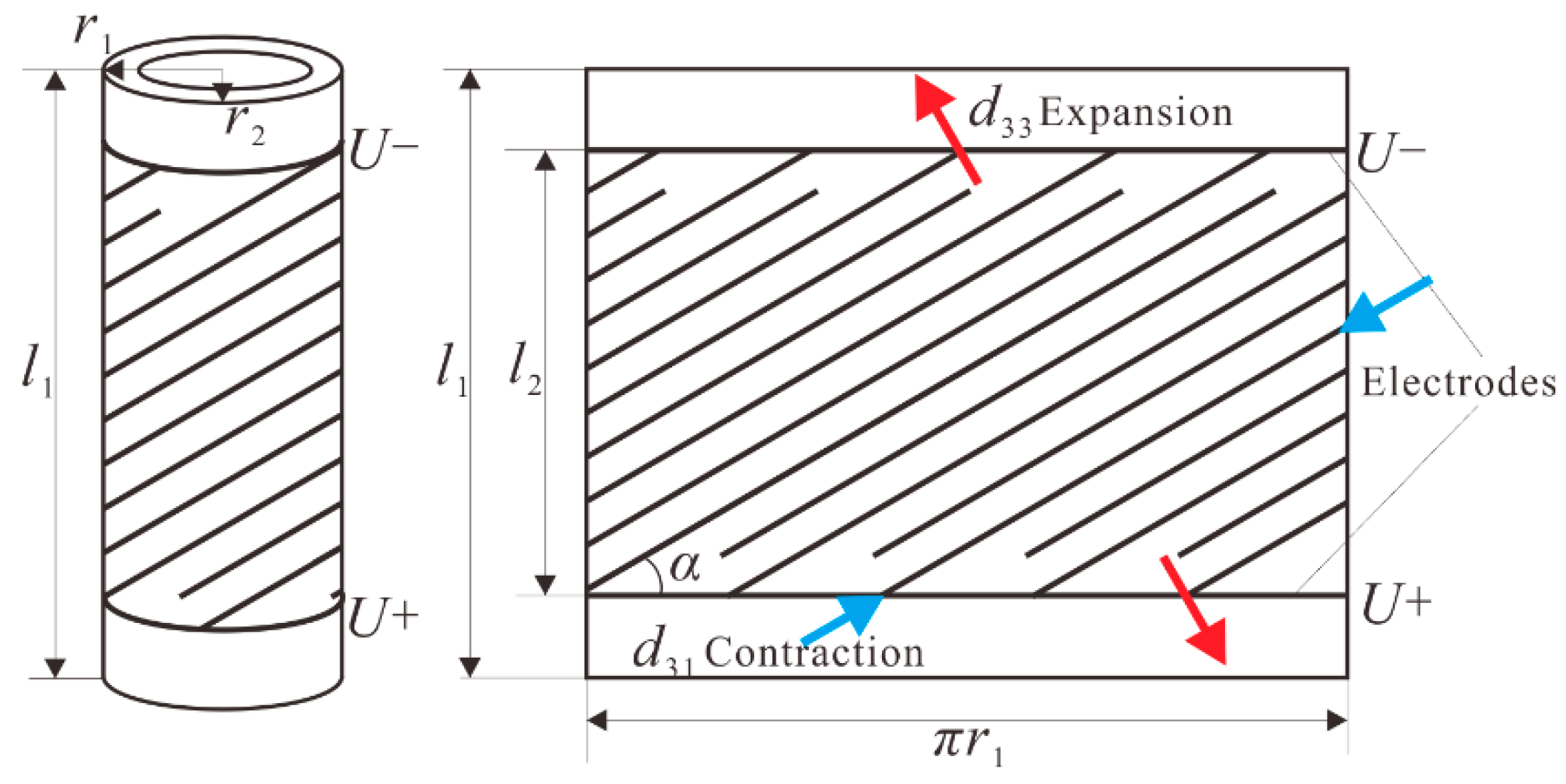
2.1. Piezoelectric Actuator

The PA is composed of a piezoelectric tube which has an even number of helical interdigitated electrodes on its outside surface. The structure of the PA and the expanded surface of the PA cutting along the longitudinal direction are shown in Figure 1. The piezoelectric tube has a total length of l1. The outer radius and inner radius of the piezoelectric tube are r1 and r2, respectively. The effective length of the electrodes is l2, the angle of helical electrodes is α, and the driving voltage applied to each two adjacent electrodes is 2U. When the direction of a stable driving electric field is the same as that of poling direction and they are perpendicular to the electrode lines, the contraction strain and expansion strain will be produced simultaneously. Thus the PA will have screw-type motion ability. The contraction strain is caused by d31 piezoelectric coefficient which is parallel to the direction of helical electrodes and the expansion strain is caused by d33 piezoelectric coefficient which is perpendicular to the direction of the electrode lines.
Theoretically, the PA will produce a load-free torsional angle and longitudinal displacement under the quasi-static driving as following [28,29]:
θ = k 1 ( d 33 d 31 ) E l 2 sin 2 α r o ,
ζ = k 2 ( d 33 cos 2 α + d 31 sin 2 α ) E l 2 ,
E = 2 U n π r o sin α ,
where k1 is compensation factor in torsional direction, k2 is compensation factor in longitudinal direction, E is the average driving electric field intensity, 2U is the driving voltage between two adjacent electrodes, n is the pairs of electrodes.
Thus, the PA will produce a screw-type motion under the control of driving voltage in theory.

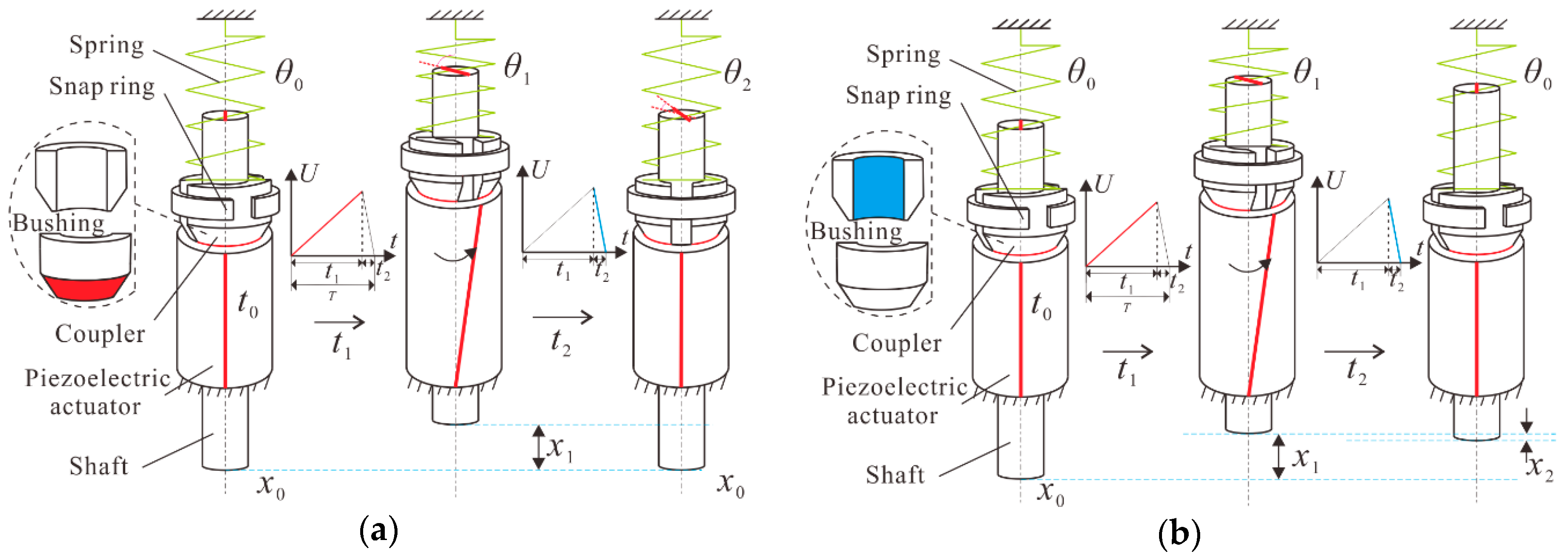
2.2. Working Principle of the Impact Rotary–Linear Motor

The simplified piezoelectric motor consists of a spring, a snap ring, a coupler, a PA, and a shaft. The coupler includes a pair of cone-shaped bushings. The outer surface of the cone-shaped bushing is mainly used as the contact surface for rotary motion and the inner surface of the coupler is used as the contact surface for linear motion. The piezoelectric motor realizes rotary motion through the line contact and realizes the linear motion through the surface contact. The coupler has different functions in rotary and linear motion. The working principle is shown in Figure 2. With an axial prepressure applied between the PA and the coupler, a friction force or friction torque will be produced when there is a trend of relative movement among them. Also, with a radial prepressure applied between the coupler and the shaft, a friction force or friction torque will be produced when there is a trend of relative movement among them. According to the different working conditions, the value of the friction force or friction torque between the coupler and the shaft and friction force or friction torque between the coupler and PA can be adjusted by choosing different sizes of snap ring and changing different positions of the spring.
The piezoelectric motor is driven by a saw-shaped voltage signal. The duty ratio in Figure 2 can be defined by:
D u t y   r a t i o = t 1 / T × 100 % = [ t 1 / ( t 1 + t 2 ) ] × 100 % ,
where T is the cycle time, t1 is the rising time of the saw-shaped driving voltage, and t2 is the falling time of the saw-shaped driving voltage.
The PA is excited by a saw-shaped driving voltage signal. The working cycle of the piezoelectric motor can be divided into two steps and three states [30]. The piezoelectric motor can realize independent rotary and linear motions by the appropriate snap ring and appropriate position of spring through the main two different friction interfaces.
For the rotary motion [see Figure 2a]:
In state 1, adjusting the spring to the suitable position and choosing the appropriate snap ring, the motor is at the starting position with the angle of θ0 and it is at the starting position with a displacement of x0 when the driving voltage is beginning to apply. In state 2, with the slow increase of the driving voltage, the PA produces a screw-type motion, in other words, the PA is extended in axial direction and twisted in circumferential direction simultaneously. The friction torque between the coupler and PA, also the friction torque between the coupler and shaft, are appropriate for the coupler and shaft to move along with the PA in circumferential direction. The friction force between the coupler and PA, also the friction force between the coupler and shaft, are appropriate for the coupler and shaft to move along with the PA in axial direction. So the shaft and the PA realize the same torsional angle of θ1 and the same longitudinal displacement of x1 at the time of t1. In state 3, with the sudden decrease of the driving voltage, the PA moves back to its initial position quickly. The coupler cannot catch the PA by the dynamic friction torque between the coupler and PA, so a small slip angle of θ2 is generated by the coupler at the time of t2. At the same time, the friction torque between the coupler and the shaft is enough for the shaft to follow the motion of coupler in circumferential direction, so the coupler and shaft can be regarded as a whole at this condition. Thus, a slip angle of θ2 is generated by the shaft at the time of t2. Finally, the shaft has the net rotary angle of θ1θ2 in one cycle, because the coupler can move back to its initial axial position under the effect of the restoring force which is produced by spring in axial direction. Moreover, the friction force between coupler and shaft is appropriate for the shaft to move along with the coupler, so the shaft will move together with the coupler to the initial position in axial direction.
After one driving cycle, the piezoelectric motor has a net rotary angle of θ1θ2 and a net linear displacement of zero. So the screw-type motion of PA can be changed into the rotary motion of shaft, and the coupler is working as a rotor at this condition. By repeating the driving voltages, the piezoelectric motor will realize continuous rotary motion. By changing the duty ratio, the piezoelectric motor will have different directions of movement.
For the linear motion [see Figure 2b]:
The state 1 and 2 of linear motion are similar to the corresponding states in the above rotary motion. The difference is the values of the friction forces or friction torques between the two friction interfaces. The shaft and the PA have the same torsional angle of θ1 and the same longitudinal displacement of x1 at the time of t1. In state 3, with the sudden decrease of the driving voltage, the PA moves back to its initial position quickly. The friction torque between the coupler and PA is large enough for the coupler to catch the PA in circumferential direction. Meanwhile, the friction torque between the coupler and shaft is large enough for the shaft to catch the coupler, thus the shaft will rotate back together with the PA to its initial position in circumferential direction. The coupler moves back quickly to its initial axial position under the effect of the restoring force which is produced by the spring in axial direction. However, the shaft cannot catch the coupler through the dynamic friction force between the coupler and shaft in axial direction. Thus, a slip displacement of x2 is generated by the shaft at the time of t2. After one driving cycle, the piezoelectric motor has the net linear displacement of x1x2 and a net rotary angle of zero. So the screw-type motion of PA can be changed into the linear motion of shaft. In the linear motion, the coupler is working as a stator and the coupler can be regarded as a part of the PA. By repeating the driving voltages, the piezoelectric motor will realize continuous linear motion. By changing the duty ratio, the piezoelectric motor will have different directions of movement.
According to the different working principles, by choosing the appropriate snap ring and adjusting the suitable position of the spring, the motor will realize independent rotary and linear motions. With the increase of driving frequency, the slip angle or slip displacement will gradually decrease and the motion of the motor will become smoother.

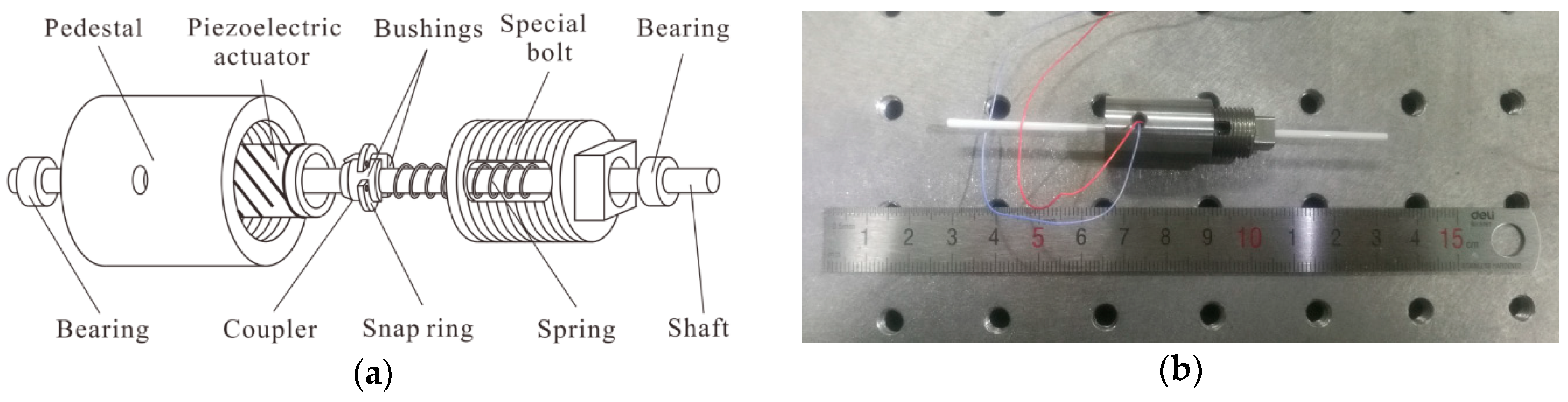
3. Fabrication of the Prototype Motor

The overall structure diagram of the piezoelectric motor and the fabricated piezoelectric motor are shown in Figure 3. The prototype motor consists of a PA, a pedestal, a coupler, a snap ring, a spring, a special bolt, a shaft, and a pair of bearings. The PA is made from the lead zirconate titanate (PZT)-type piezoelectric tube (YT-5L, Baoding Yitian Ultrasonic Technology co., LTD, Baoding, China) The key material parameters of the PA are shown in Table 1.
The length of the piezoelectric tube is 15 mm, the outer radius is 3 mm, and the inner radius is 2.5 mm. The effective length of the surface helical interdigitated electrodes of the PA is 9 mm, the angle of electrodes is 30°, and the intensity of the polarizing electric field is 2 kV/mm. The PA can produce screw-type motion under saw-shaped driving voltage. One end of the PA is glued to the pedestal by epoxy resin. The inner surface of the coupler is in contact with the shaft, the cone-shaped end of the coupler is tangent to the inner surface of the PA, and the outer cylindrical surface of the coupler is fixed by the snap ring. The coupler is made up of a pair of bushings with alumina ceramic. The snap ring can be changed to different dimensions so that the radial prepressure between the coupler and shaft can be adjusted according to different motions. By adjusting the position of the special bolt, the length of the spring will be changed, thus the axial prepressure between the coupler and PA can be changed. The two different kinds of prepressure will provide different friction force or friction torque between the contact surfaces of the contact objects when there is a trend of relative movement among them. A pair of bearings is used to support and guide the motions of the shaft. The shaft has a diameter of 2 mm with a length of 100 mm and it is made by zirconia ceramic. The fabricated prototype motor has a maximum diameter of 15 mm with a length of 100 mm.

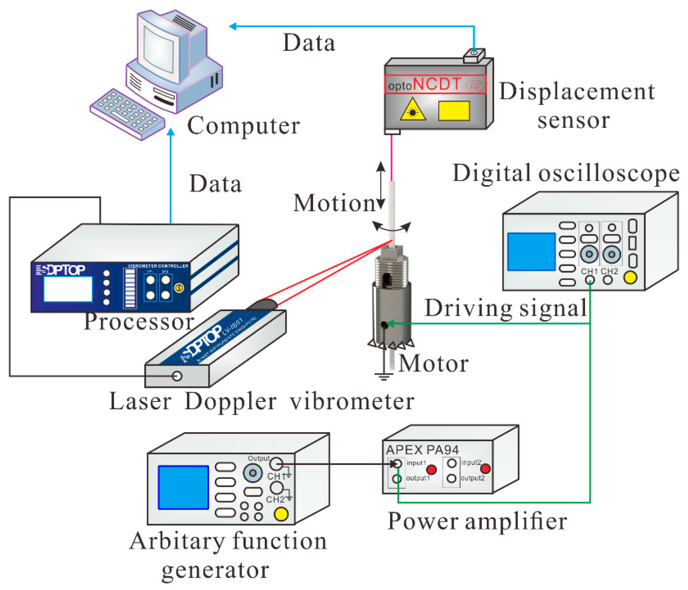
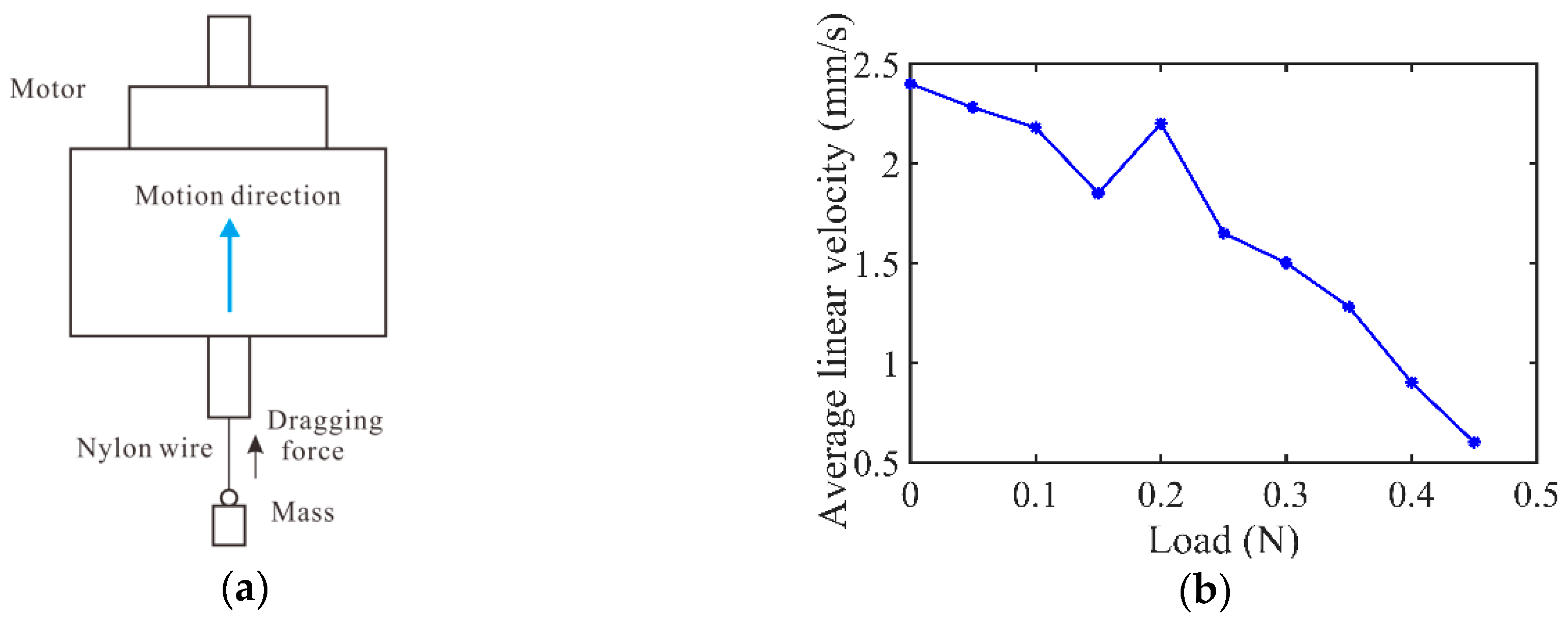
4. Experimental Tests and Discussions

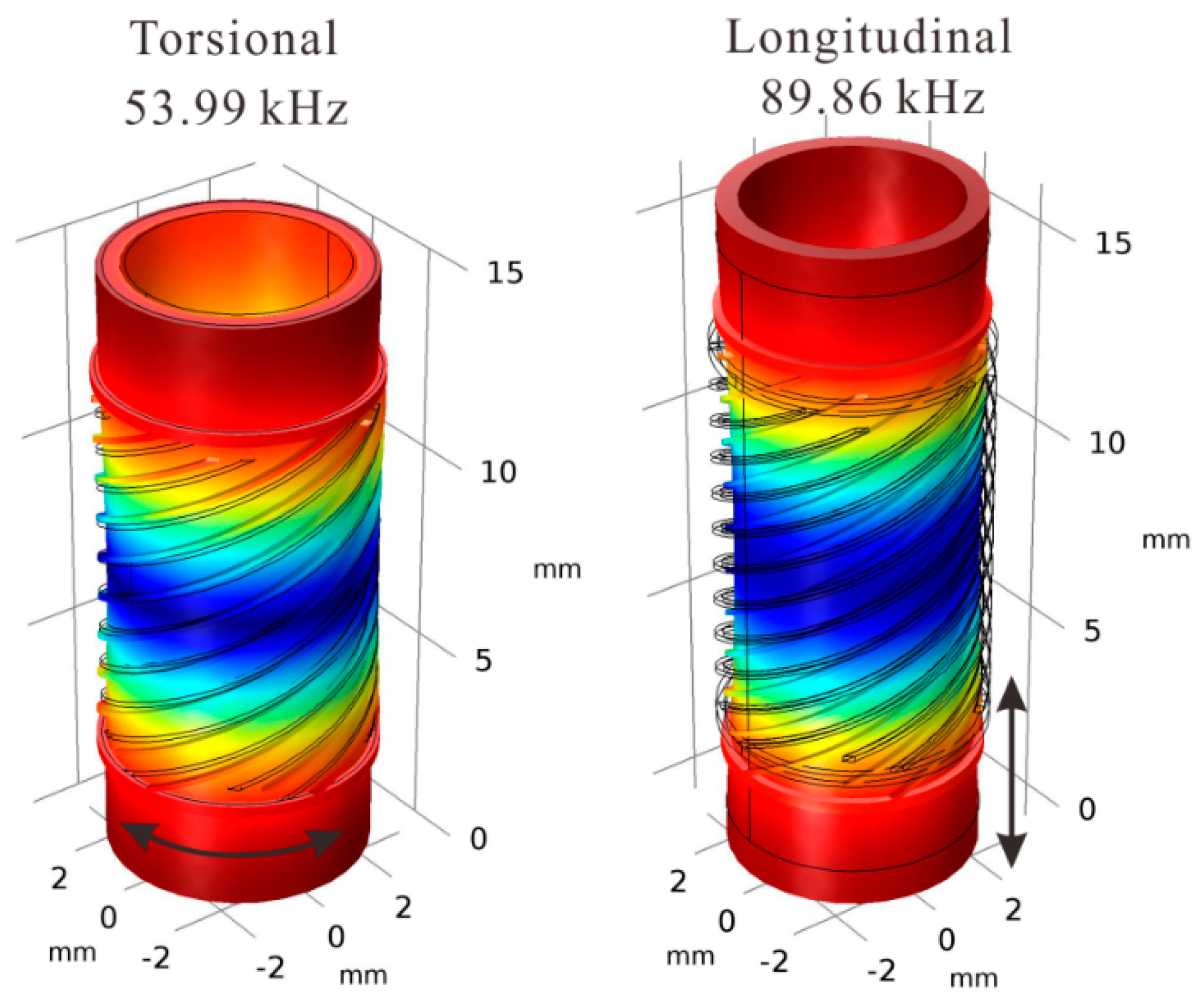
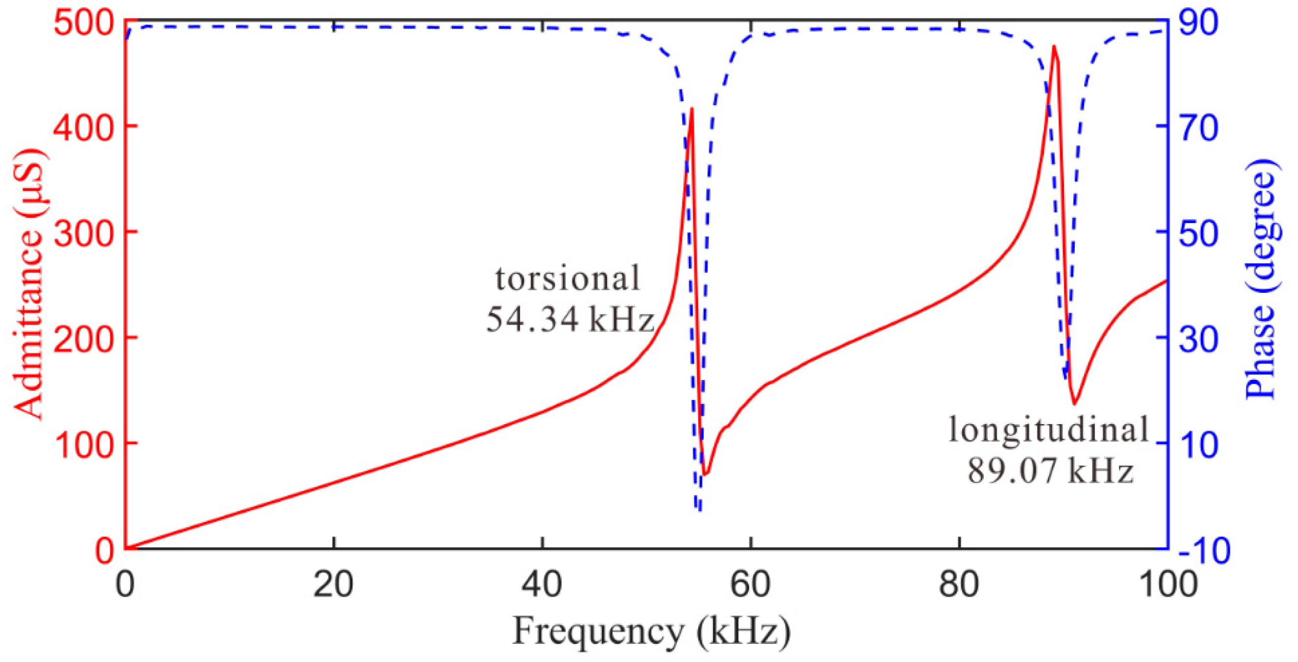
4.1. Dynamic Performance of the PA

The finite element method (FEM) is used to extract the torsional and longitudinal vibration modes of the PA with free boundary condition, and the results are shown in Figure 4. The torsional and longitudinal vibration modes occur at 53.99 kHz and 89.86 kHz, respectively.
The dynamic response is measured by LCR-8105G analyzer (Good will Instrument Company Ltd., Taiwan), which is shown in Figure 5. The torsional and longitudinal vibration modes occur at 54.34 kHz and 89.07 kHz, respectively. The experimental results are close to the simulation results. The experimental results of the dynamic performance indicate that the prototype PA has the screw-type motion ability.

4.2. Prototype Motor

The principle of the experimental test is shown in Figure 6. The outer surface of the pedestal is fixed by a machine clap. The original voltage signal is generated by arbitrary function generator. The driving signal is an amplified saw-shaped driving voltage signal which is amplified by the original signal through the power amplifier. A displacement sensor (optoNCDT2300, Micro-epsilon, Ortenburg, Germany) is used to test the longitudinal displacement of the shaft. The Laser Doppler Vibrometer system (Sunny Optical Technology (Group) Co., LTD, Yuyao, China) can test the tangential displacement of the shaft, thus the torsional angle of the shaft can be calculated. The digital oscilloscope (RIGOL DS 1052D, Beijing, China) is used to observe the driving signal.
The rotary and linear motions of the shaft are tested simultaneously to determine the motion state of the prototype motor. By adjusting the position of the special bolt and choosing the appropriate snap ring, the prototype motor will realize independent rotary motion and linear motion, respectively. The rotary and linear motion with no load are tested first, and then the load capacity is tested.

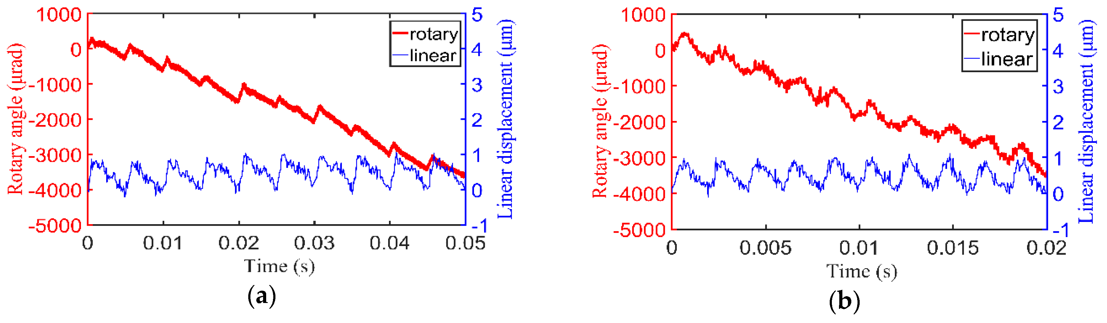
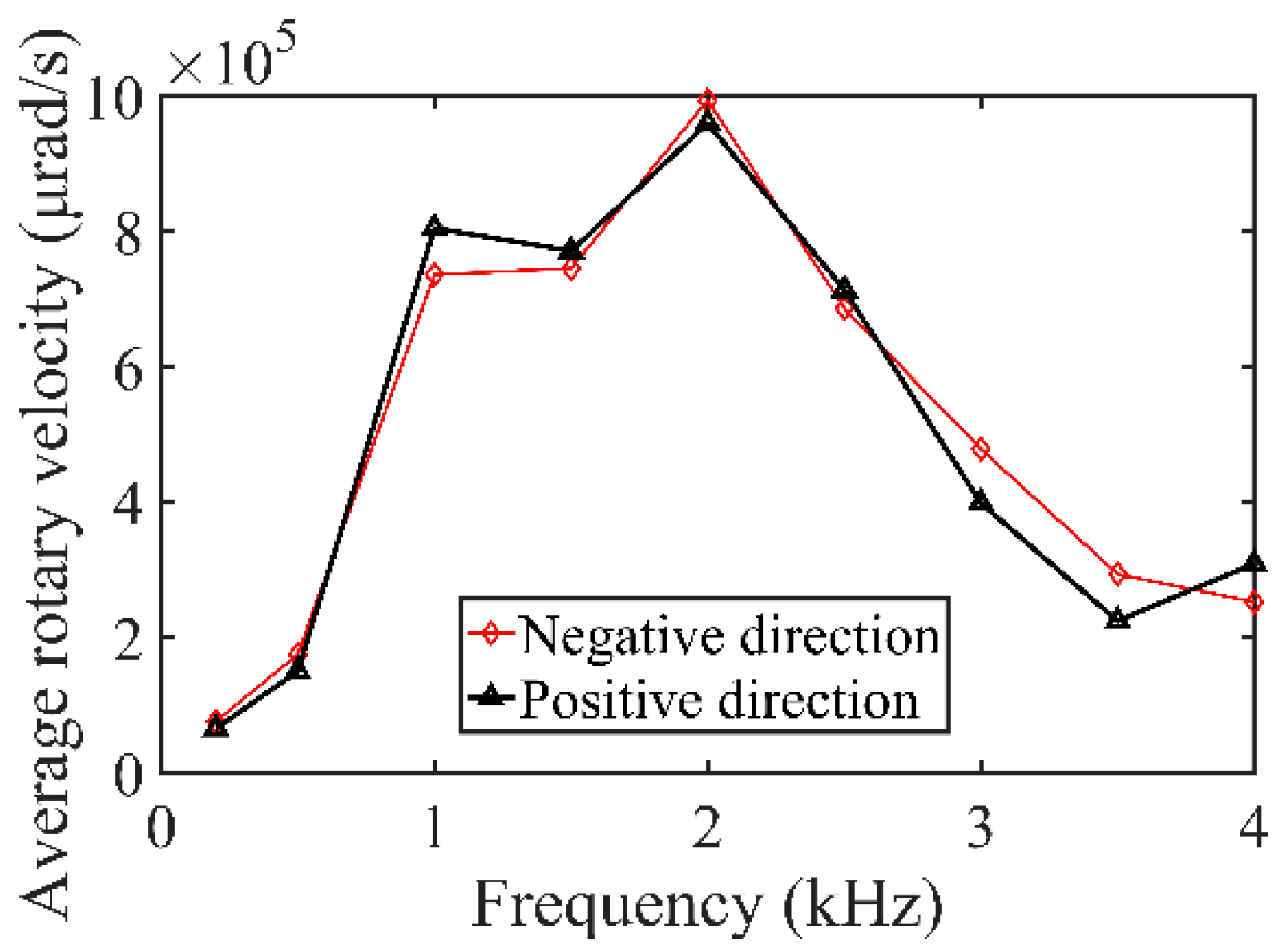
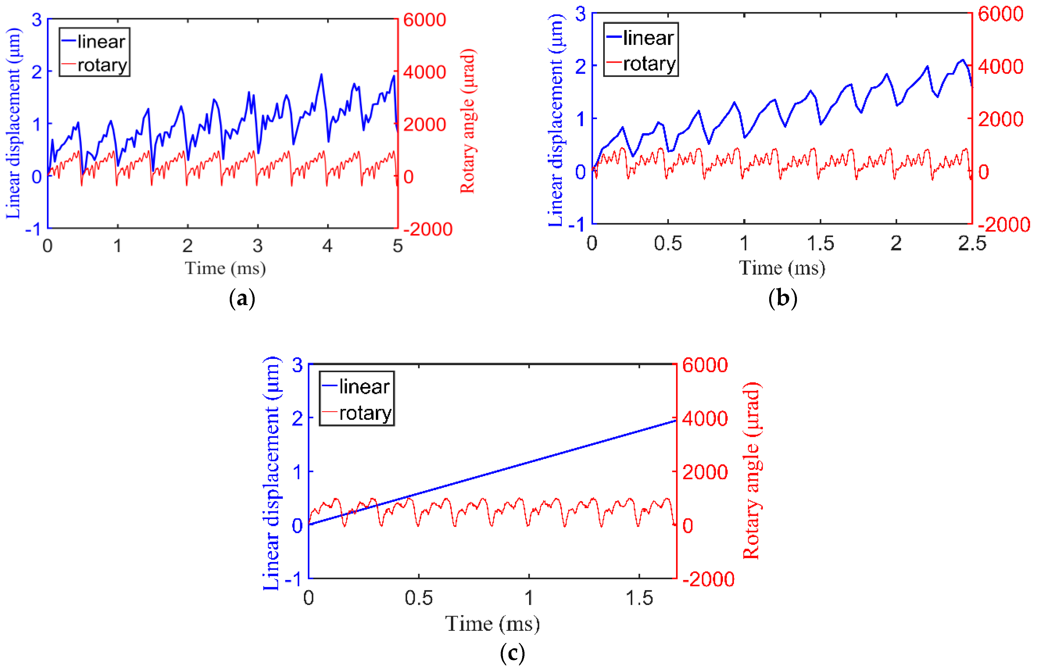
4.2.1. Rotary Motion of the Prototype Motor with No Load

When adjusting the axial prepressure generated by spring to about 1 N and adjusting the radial prepressure generated by snap ring to about 14 N, the prototype motor realizes rotary motion under the saw-shaped driving voltage. Meanwhile, the measured friction torque between the PA and coupler is about 0.0003 N∙m and the measured friction force between the coupler and shaft tested is about 4.2 N in axial direction.
When the driving voltage is 720 Vp-p with a duty ratio of 0%, and the driving frequency is 200 Hz, 500 Hz, and 1 kHz, the output rotary angles and linear displacement of the prototype motor in the two directions are shown in Figure 7. Assuming this driving voltage can produce the negative movement of the motor at this driving voltage, when the duty ratio of the driving voltage is 100%, the motor will realize positive movement. According to Equations (1)–(3), when the compensation factor is ideal and is equal to 1, the calculated maximum rotary angle of the PA is 1280 μrad and the maximum linear distance is 1.98 μm.
From the results shown in Figure 7, the piezoelectric motor can realize continuous rotary motion. The tested maximum rotary angle of the PA is about 1000 μrad and the maximum linear distance is about 1.03 μm. Due to the imperfect processing technology of the piezoelectric tube, manufacturing error, and installation accuracy, the compensation factor k1 is 0.8 and the compensation factor k2 is 0.5. With the increase of driving frequency, the slip angle becomes smaller and smaller, and the rotary motion becomes more and more smooth.
When the driving frequency continues to increase and other conditions remain unchanged, the prototype motor will keep rotary motion until the driving frequency reaches 4 kHz. By changing the duty ratio, the motor can rotate in reverse direction. The two directions of the average rotary velocity of the prototype motor are tested when the driving frequency ranges from 200 Hz to 4 kHz, and the results are shown in Figure 8. The results show that the prototype motor can realize rotary motion from 200 Hz to 4 kHz, and the prototype motor can achieve the maximum rotary velocity of about 9.9 × 10⁵ μrad/s at 2 kHz under the driving voltage of 720 Vp-p with a duty ratio of 0%.

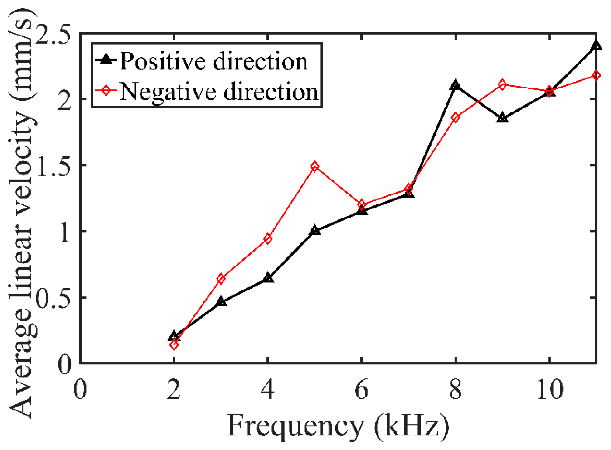
4.2.2. Linear Motion of the Prototype Motor with No Load

When adjusting the axial prepressure generated by spring to about 11.7 N and adjusting the radial prepressure generated by snap ring to about 21.1 N, the piezoelectric motor realizes linear motion under the saw-shaped driving voltage. Meanwhile, the measured friction torque between the PA and coupler is about 0.0035 N∙m and the measured friction force between coupler and shaft is about 6.3 N in axial direction.
When the driving voltage is 720 Vp-p with a duty ratio of 100%, and the driving frequency is 2 kHz, 4 kHz, and 6 kHz, the output rotary angle and linear displacement of the prototype motor in the two directions are shown in Figure 9. As the motor can realize negative movement when the duty ratio of the driving voltage is 0%, the motor will realize positive movement when the duty ratio of the driving voltage is 100%. The tested maximum rotary angle of the PA is about 1012 μrad and the maximum linear distance is about 1.01 μm; the maximum angle and distance are similar to the results in the rotary motion. With the increase of driving frequency, the slip displacement becomes smaller and smaller, and the linear motion becomes more and more smooth.
When driving frequency continues to increase and other conditions remain unchanged, the prototype motor will keep positive linear motion until the driving frequency reaches 11 kHz. By changing the duty ratio, the motor can move in reverse direction. The two directions of the average linear velocity of the prototype motor are tested when the driving frequency ranges from 2 kHz to 11 kHz, and the results are shown in Figure 10. The results show that the prototype motor can realize linear motion from 2 kHz to 11 kHz, and the prototype motor can achieve the maximum linear velocity of about 2.4 mm/s at 11 kHz under the driving voltage of 720 Vp-p with a duty ratio of 100%.

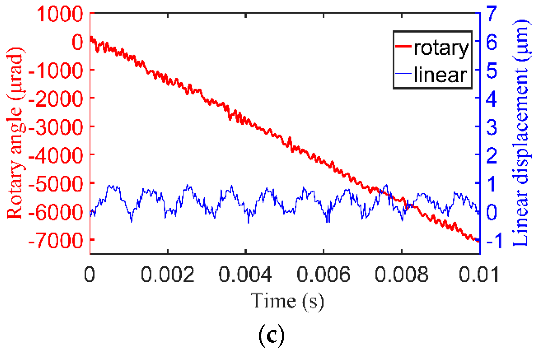
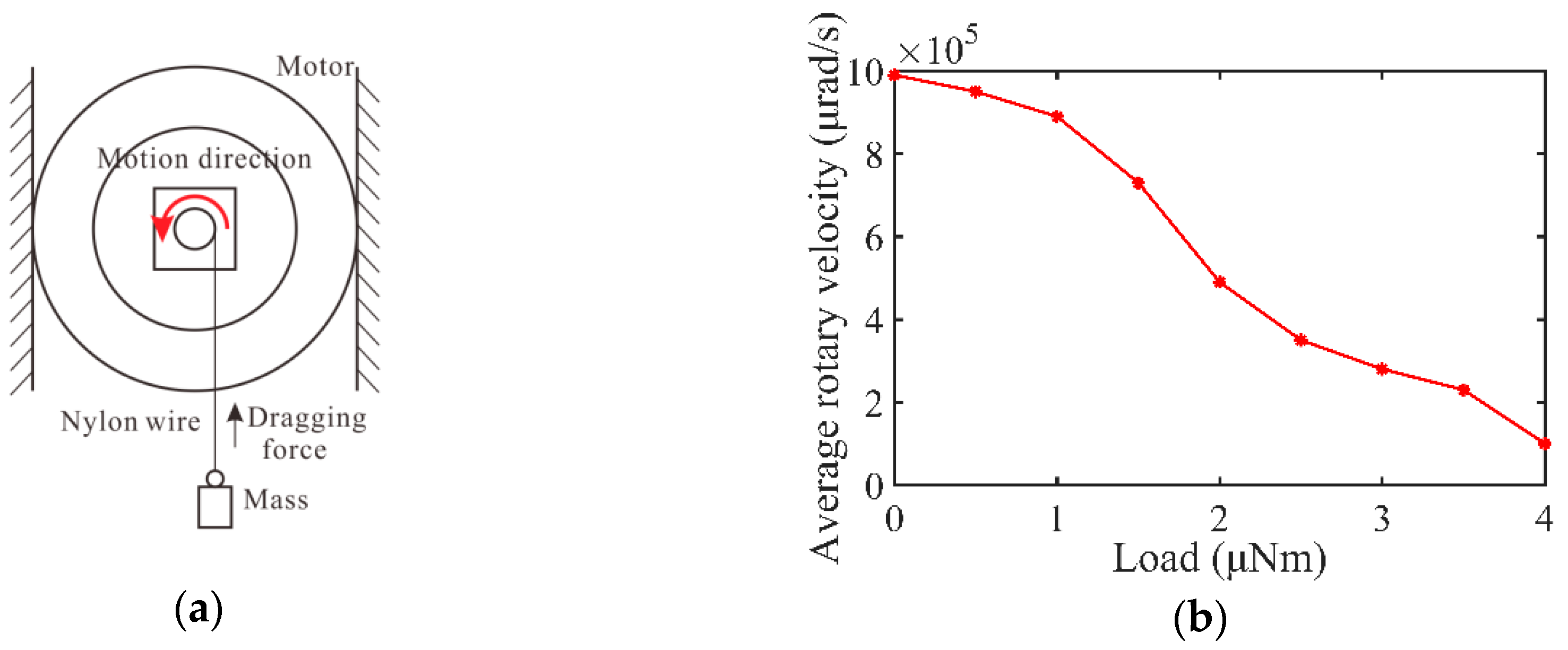
4.2.3. Load Capacity

Load capacity is an important characteristic of actuators. The load capacity of rotary motion and linear motion are tested individually.
The nylon wire is used to tow the mass and is connected to the rotary shaft. When the driving voltage is fixed at 720 Vp-p with the driving frequency of 2 kHz under the duty ratio of 0%, the average rotary velocities of the motor will be tested under different loads. The load testing system and the results of average rotary velocities under different torques are shown in Figure 11.
The nylon wire is used to tow the mass and is connected to the center of the shaft. When the driving voltage is fixed at 720 Vp-p with the driving frequency of 11 kHz under the duty ratio of 100%, the average linear velocities of the motor will be tested under different loads. The load-testing system and results of average linear velocities are shown in Figure 12.
The results in Figure 11 and Figure 12 show that the maximum output torque and output force of the prototype are 4 μNm and 0.45 N, respectively.
In Table 2, some proposed motors which can realize rotary and linear motions are compared with the prototype motor in terms of the working principle, the main size when removing the output shaft, the peak-to-peak driving voltage, the maximum rotary velocity, the output torque, the maximum linear velocity, and the output force. Table 2 shows that the prototype motor has higher velocity compared to the inchworm actuator which is proposed by Sun [13] and the load capacity is stronger than the ultrasonic actuator which is proposed by Mashimo [14]. The speed of motion of the prototype motor is similar to the impact motor which is proposed by Zhang [12]. The prototype motor has more compact structure compared to the proposed motors in references [12,13], and the control of the prototype motor is simple compared to the proposed motor in reference [14].

5. Conclusions

A novel rotary–linear impact piezoelectric motor based on a PA with helical interdigitated electrodes has been fabricated and tested. By two different friction interfaces and two adjusting systems, the piezoelectric motor can realize independent linear and rotary motion under suitable conditions. The prototype motor can realize positive and negative rotary motion from 200 Hz to 4 kHz under the driving voltage of 720 Vp-p and it can reach about 9.9 × 10⁵ μrad/s at 2 kHz with no load. The prototype motor can realize positive and negative linear motion from 2 kHz to 11 kHz under the driving voltage of 720 Vp-p and it can achieve about 2.4 mm/s at 11 kHz with no load.
The prototype motor can obtain a maximum rotary angle of about 1000 μrad and a maximum linear displacement of about 1.03 μm at a driving voltage of 720 Vp-p, so the motor can be used in precision positioning. This study provides a way of expending the DOF of motor, which will not only meet the complex manipulation but also benefit the miniaturization of structure. Although the screw-type motion can be decomposed to single rotary and linear motion by this adjustable structure, it is difficult to adjust the appropriate values of friction torques and friction forces in the experiments. The spring not only decides the friction force between the coupler and PA, but it also provides the restoring force in the axial direction. It is more convenient and feasible to separate the rotary and linear motion by the different driving voltages, and it will be in future research work.

Author Contributions

All authors conceived the structure and analyzed the data; L.H. analyzed the working principle of the structure; L.H. and C.P. did the experimental tests; Y.J. made the graphs, L.H. wrote the paper; H.Z. and L.Y. contributed to revising the paper.

Funding

This work was supported by the National Natural Science Foundation of China (Nos. 51775157, 51875165), the Project 111 (No. B12019), the National Key Scientific Apparatus Development Project (Grant No.2013YQ220893) and the Natural Science Foundation of Anhui Province (No. 1608085ME108).

Acknowledgments

The authors would like to express their gratitude to the reviewers and editors for their kind help.

Conflicts of Interest

The authors declare no conflict of interest.

References

  1. Hunstig, M.; Hemsel, T.; Sextro, W. High-velocity operation of piezoelectric inertia motors: Experimental validation. Arch. Appl. Mech. 2016, 86, 1733–1741. [Google Scholar] [CrossRef]
  2. Wen, J.M.; Ma, J.J.; Zeng, P.; Cheng, G.M.; Zhang, Z.H. A new inertial piezoelectric rotary actuator based on changing the normal pressure. Microsyst. Technol. 2013, 19, 277–283. [Google Scholar] [CrossRef]
  3. Deng, J.; Liu, Y.X.; Chen, W.S.; Liu, J.K. Development and experiment evaluation of an inertial piezoelectric actuator using bending-bending hybrid modes. Sens. Actuators A Phys. 2018, 275, 11–18. [Google Scholar] [CrossRef]
  4. Han, W.X.; Zhang, Q.; Ma, Y.T.; Pan, C.L.; Feng, Z.H. An impact rotary motor based on a fiber torsional piezoelectric actuator. Rev. Sci. Instrum. 2009, 80, 273. [Google Scholar] [CrossRef] [PubMed]
  5. Chen, C.; Liu, M.; Wang, Y.Z. A dual stage low power converter driving for piezoelectric actuator applied in micro mobile robot. Appl. Sci. 2018, 8, 1666. [Google Scholar] [CrossRef]
  6. Ru, C.; Pan, P.; Chen, R. The Development of Piezo-Driven Tools for Cellular Piercing. Appl. Sci. 2016, 6, 314. [Google Scholar] [CrossRef]
  7. Lee, S.W.; Ahn, K.G.; Ni, J. Development of a piezoelectric multi-axis stage based on stick-and-clamping actuation technology. Smart Mater. Struct. 2007, 16, 2354–2367. [Google Scholar] [CrossRef]
  8. Chen, W.M.; Liu, T.S. Modeling and experimental validation of new two degree-of-freedom piezoelectric actuators. Mechatronics 2013, 23, 1163–1170. [Google Scholar] [CrossRef]
  9. Guo, M.S.; Hu, J.H.; Zhu, H.; Zhao, C.S.; Dong, S.X. Three-degree-of-freedom ultrasonic motor using a 5-mm-diameter piezoelectric ceramic tube. IEEE Trans. Ultrason. Ferroelectr. Freq. Control 2013, 60, 1446–1452. [Google Scholar] [CrossRef]
  10. Peng, Y.X.; Ito, S.; Sakurai, Y.; YUki, S.M.; Gao, W. Construction and verification of a linear-rotary micro-stage with a millimeter-scale range. Int. J. Precis. Eng. Manuf. 2013, 14, 1623–1628. [Google Scholar] [CrossRef]
  11. Gao, W.; Sato, S.; Arai, Y. A linear-rotary stage for precision positioning. Precis. Eng. 2010, 34, 301–306. [Google Scholar] [CrossRef]
  12. Zhang, Y.; Liu, G.; Hesselbach, J. On development of a rotary–linear actuator using piezoelectric translators. IEEE/ASME Trans. Mechatron. 2006, 11, 647–650. [Google Scholar] [CrossRef]
  13. Sun, X.T.; Chen, W.H.; Zhang, J.B.; Zhou, R.; Chen, W.J. A novel piezo-driven linear-rotary inchworm actuator. Sens. Actuators A Phys. 2015, 224, 78–86. [Google Scholar] [CrossRef]
  14. Mashimo, T.; Toyama, S. Rotary-linear piezoelectric microactuator with a cubic stator of side length 3.5 mm. IEEE Trans. Ultrason. Ferroelectr. Freq. Control 2010, 57, 1825–1830. [Google Scholar] [CrossRef] [PubMed]
  15. Blackford, B.L.; Jericho, M.H. Simple two-dimensional piezoelectric micropositioner for a scanning tunneling microscope. Rev. Sci. Instrum. 1990, 61, 182–184. [Google Scholar] [CrossRef]
  16. Koc, B.; Cagatay, S.; Uchino, K. A piezoelectric motor using two orthogonal bending modes of a hollow cylinder. IEEE Trans. Ultrason. Ferroelectr. Freq. Control 2002, 49, 495–500. [Google Scholar] [CrossRef] [PubMed]
  17. Chu, X.C.; Wang, J.W.; Yuan, S.M.; Li, L.T.; Cui, H.C. A screw-thread-type ultrasonic actuator based on a Langevin piezoelectric vibrator. Rev. Sci. Instrum. 2014, 85, 065002. [Google Scholar] [CrossRef] [PubMed]
  18. Li, H.; Wang, L.; Cheng, T.; He, M.; Zhao, H.; Gao, H. A High-Thrust Screw-Type Piezoelectric Ultrasonic Motor with Three-Wavelength Exciting Mode. Appl. Sci. 2016, 6, 442. [Google Scholar] [CrossRef]
  19. Cheng, T.; Wang, L.; Yin, M.; Song, Z.; Zhu, D. Design and analysis of a cylindrical screw-type ultrasonic motor driven by six transducers. In Proceedings of the 2015 Symposium on Piezoelectricity, Acoustic Waves, and Device Applications (SPAWDA), Jinan, China, 30 October–2 November 2015. [Google Scholar] [CrossRef]
  20. Chang, L.K.; Tsai, M.C. Design of single-phase driven screw-thread-type ultrasonic motor. Rev. Sci. Instrum. 2016, 87, 055002. [Google Scholar] [CrossRef]
  21. Dong, L.; Zhang, L.; Kratochvil, B.E.; Shou, K.; Nelson, B.J. Dual-Chirality Helical Nanobelts: Linear-to-Rotary Motion Converters for Three-Dimensional Microscopy. J. Microelectromech. Syst. 2009, 18, 1047–1053. [Google Scholar] [CrossRef]
  22. Wen, B.H.; Liu, L.; Liu, S.Y.; Zheng, K.X.; Hua, L.; Wang, S. Analysis and Research of Force and Motion of Screw-Type Extrusion Molding Biomass. Adv. Mater. Res. 2013, 614–615, 452–459. [Google Scholar] [CrossRef]
  23. Jing, Q.S.; Zhu, G.; Wu, W.Z.; Bai, P.; Xie, Y.N.; Han, R.P.S.; Wang, Z.L. Self-powered triboelectric velocity sensor for dual-mode sensing of rectified linear and rotary motions. Nano Energy 2014, 10, 305–312. [Google Scholar] [CrossRef]
  24. Watson, B.; Friend, J.; Yeo, L. BRIEF COMMUNICATION: Piezoelectric ultrasonic resonant motor with stator diameter less than 250 µm: The Proteus motor. J. Micromech. Microeng. 2009, 19, 22001–22005. [Google Scholar] [CrossRef]
  25. Wajchman, D.; Liu, K.C.; Friend, J.; Yeo, L. An ultrasonic piezoelectric motor utilizing axial-torsional coupling in a pretwisted non-circular cross-sectioned prismatic beam. IEEE Trans. Ultrason. Ferroelectr. Freq. Control 2008, 55, 832–840. [Google Scholar] [CrossRef] [PubMed]
  26. Pan, C.L.; Feng, Z.H.; Ma, Y.T.; Shao, W.W.; Liu, Y.B. Coupled torsional and longitudinal vibrations of piezoelectric fiber actuator with helical electrodes. IEEE Trans. Ultrason. Ferroelectr. Freq. Control 2011, 58, 829–837. [Google Scholar] [CrossRef] [PubMed]
  27. Qi, Z.; Pan, C.L.; Ma, Y.T.; Kong, F.R.; Feng, Z.H. Piezoelectric rotary motor based on active bulk torsional element with grooved helical electrodes. IEEE/ASME Trans. Mechatron. 2012, 17, 260–268. [Google Scholar] [CrossRef]
  28. Pan, C.L.; Feng, Z.H.; Ma, Y.T.; Liu, Y.B. Small torsional piezoelectric fiber actuators with helical electrodes. Appl. Phys. Lett. 2008, 92, 012923. [Google Scholar] [CrossRef]
  29. Pan, C.L.; Ma, Y.T.; Liu, Y.B.; Zhang, Q.; Feng, Z.H. Torsional displacement of piezoelectric fiber actuators with helical electrodes. Sens. Actuators A Phys. 2008, 148, 250–258. [Google Scholar] [CrossRef]
  30. Han, L.L.; Zhao, H.N.; Xia, H.J.; Pan, C.L.; Jiang, Y.Z.; Li, W.S.; Yu, L.D. A compact impact rotary motor based on a piezoelectric tube actuator with helical interdigitated electrodes. Sensors 2018, 18, 2195. [Google Scholar] [CrossRef] [PubMed]
Figure 1. Schematic diagram of PA.
Applsci 08 02492 g001
Figure 2. Working principle of the piezoelectric motor: (a) rotary motion; (b) linear motion.
Applsci 08 02492 g002
Figure 3. The structure of the piezoelectric motor: (a) schematic diagram of the piezoelectric motor; (b) photograph of the fabricated prototype motor.
Applsci 08 02492 g003
Figure 4. FEM analysis results of PA.
Applsci 08 02492 g004
Figure 5. Dynamic response of the PA.
Applsci 08 02492 g005
Figure 6. Schematic diagram of experimental testing system of prototype motor.
Applsci 08 02492 g006
Figure 7. The output motions of the prototype motor under different driving frequencies: (a) 200 Hz; (b) 500 Hz; (c) 1 kHz.
Applsci 08 02492 g007aApplsci 08 02492 g007b
Figure 8. The rotary velocities of the prototype motor under different driving frequencies.
Applsci 08 02492 g008
Figure 9. The output motions of the prototype motor under different driving frequencies: (a) 2 kHz; (b) 4 kHz; (c) 6 kHz.
Applsci 08 02492 g009
Figure 10. The linear velocities of the prototype motor under different driving frequencies.
Applsci 08 02492 g010
Figure 11. Load capacity of rotary motion: (a) testing system; (b) average rotary velocity under different external loads at 2 kHz.
Applsci 08 02492 g011
Figure 12. Load capacity of linear motion: (a) testing system; (b) average linear velocity under different external loads at 11 kHz.
Applsci 08 02492 g012
Table 1. Material parameters of the PA.
MaterialParametersValueUnit
Piezoelectric tube: PZT (YT-5L, Baoding Yitian Ultrasonic Technology co., LTD)Piezoelectric coefficient (d31)−195pC × N−1
Piezoelectric coefficient (d33)450pC × N−1
Density7600kg × m−3
Table 2. Performance comparisons with previous actuator.
AuthorZhang [12]Sun [13]Mashimo [14]This Study
PrincipleImpactInchwormUltrasonicImpact
Main size (mm)40 × 55 (rotation part)
25 × 25 (translation part)
88 × 88 × 723.5 × 3.5 × 3.515 × 15 × 40
Driving voltage (V)N/A140.0118.8720.0
Maximum rotary velocity (μrad/s)2.0 × 10534,2702.4 × 1079.9 × 105
Output torque (μNm)1.22 × 1047.35 × 1042.54.0
Maximum linear velocity (mm/s)7.321.4580.02.4
Output force (N)2.0911.82.6 × 1030.45

