Article

Dynamic Analytical Solution of a Piezoelectric Stack Utilized in an Actuator and a Generator

1
School of Civil Engineering, North China University of Technology, Beijing 100144, China
2
Department of Applied Mechanics, University of Science and Technology Beijing, Beijing 100083, China
3
School of Civil and Environmental Engineering, Harbin Institute of Technology, Shenzhen 518055, China
*
Author to whom correspondence should be addressed.
Appl. Sci. 2018, 8(10), 1779; https://doi.org/10.3390/app8101779
Submission received: 27 August 2018 / Revised: 13 September 2018 / Accepted: 21 September 2018 / Published: 30 September 2018
(This article belongs to the Special Issue Piezoelectric Actuators)

Abstract

:
This paper presents the dynamic analytical solution of a piezoelectric stack utilized in an actuator and a generator based on the linear piezo-elasticity theory. The solutions for two different kinds of piezoelectric stacks under external load were obtained using the displacement method. The effects of load frequency and load amplitude on the dynamic characteristics of the stacks were discussed. The analytical solutions were validated using the available experimental results in special cases. The proposed model is able not only to predict the output properties of the devices, but also to reflect the inner electrical and mechanical components, which is helpful for designing piezoelectric actuators and generators in a comprehensive manner.

1. Introduction

The piezoelectric stack is an excellent smart device that is formed of multiple piezoelectric layers connected in parallel electrically and in series mechanically [1,2,3]. Similar to laminated piezoelectric beams [4,5,6,7,8,9,10], piezoelectric plates [11,12], cement-based piezoelectric composites [13,14,15,16,17,18], and piezoelectric shells [19,20], piezoelectric stack actuators and generators increase displacement output and power output, attracting a lot of attention.
In the past few decades, two kinds of models have been proposed to help understand and design piezoelectric stack devices. The models of the first kind are finite element models (FEMs) [21,22,23,24,25,26]. These models usually employ a commercial software package, such as ANSYS, to assist the performance analysis. They can establish an actual three-dimensional model to perform comprehensive numerical simulation. The models of the second kind are theoretical models, including a simplified model that requires the operating frequency to be far from the resonance frequency [27,28,29,30], the single degree of freedom model [31,32], the equivalent circuit model [33,34,35,36,37,38], the model based on the principle of energy conservation [39], the electromechanical impedance model [40], the simple distributed-parameter model [41], and the simplified transfer matrix model [42]. These models greatly promote the development and application of piezoelectric stacks in various engineering fields, such as energy harvesting from human motion [32,33,34,43], railway and roadway traffic-induced vibration [44,45], fuel injectors [46,47], and ultrasonic transducers [48,49,50].
However, in comparison to FEMs, most of the theoretical models of piezoelectric stacks in previous works generally assume that the electric field is spatially constant, which is inaccurate when the piezoelectric layer is thick. In addition, these theoretical models mainly focus on displacement and power outputs, while neglecting the inner electrical and mechanical components. There are some insufficiencies in designing the integrated performance of piezoelectric stack devices. For example, in the electromechanical impedance model [40], the piezoelectric stack was first treated as a monolithic element to solve the mechanical properties. Then, it was treated as multiple individual wafers and the middle values of every wafer were approximately adopted to calculate the electrical properties. In the single degree of freedom model [32], the piezoelectric stack was simplified as a spring-mass system to calculate the power output. These two models adopted the spatially constant assumption in the electric field, and did not involve the continuity of displacement and stress between the two layers, which do not reflect the inner electromechanical coupling behavior of the piezoelectric stack. To give accurate theoretical guidance for designing the piezoelectric stack, an improved theoretical model is of great significance.
Piezo-elasticity theory has been successfully used to study piezoelectric composite structures, including piezoelectric curved actuators [51,52], multi-layer piezoelectric cantilever [4,6] and cement-based piezoelectric composites [15,53], functionally graded piezoelectric beams [54,55], and laminated piezoelectric hollow spheres [56]. In addition, assuming the electric field to be spatially varying rather than spatially constant is more accurate for describing the electric field [57,58], which is still not well-applied in the analysis of piezoelectric stacks. These advantages of the methods can effectively supplement existing theories about the piezoelectric stack.
This study aims to obtain the dynamic analytical solution of the piezoelectric stack utilized in an actuator and generator based on the linear piezo-elasticity theory. The remaining sections are organized as follows: the basic equations for piezoelectric stacks are given in Section 2; in Section 3, by using the displacement method, the dynamic analytical solutions of two different kinds of piezoelectric stacks under external load are derived; in Section 4, the dynamic analytical solutions are verified using the results from other related experimental investigations, and the effects of load frequency and load amplitude on the dynamic characteristics of the stacks are investigated; finally, some conclusions are provided in Section 5.

2. Basic Equations

Two kinds of piezoelectric stacks are considered in the present paper, the piezoelectric stack under a voltage load (Model A) and the piezoelectric stack under a uniformly distributed load (Model B), as shown in Figure 1. The piezoelectric layers are connected in series mechanically, but in parallel electrically. The number of piezoelectric layers is N. The thickness of piezoelectric layer i is determined by h i h i 1 . Here, it should be noted that the thickness of the first layer is h 1 h 0 , and its upper and lower surfaces are located at z = h 1 and z = 0 , respectively. To define the thickness of each layer using the above formula, we let h 0 = 0 . All the piezoelectric layers are polarized in the z-direction. For the even layers, the polarization direction is the positive z-direction, and the piezoelectric coefficient is defined as + d 33 . For the odd layers, the polarization direction is the negative z-direction, and the piezoelectric coefficient is defined as d 33 .
According to the linear piezo-elasticity theory, in cases without body force and body charge, the basic equations for piezoelectric material in the piezoelectric layer i can be written as:
{ ρ P i 2 u P i t 2 = σ z P i z σ z P i = C 33 P i ε z P i e 33 i E z i ε z P i = u P i z  
{ D z i = e 33 i ε z P i + κ 33 i ε E z i E z i = ϕ i z D z i z = 0  
where ρ P i is the density of the piezoelectric material; u P i , σ z P i , and ε z P i are the displacement, stress, and strain in the z-direction, respectively; and D z i , E z i , and ϕ i are the electric displacement, electric field, and electric potential, respectively. C 33 P i = 1 S 33 P i , e 33 i = d 33 i S 33 P i = d 33 i C 33 P i , κ 33 i ε = κ 33 i σ d 33 i 2 S 33 P i = κ 33 i σ d 33 i 2 C 33 P i , where S 33 P i , d 33 i , and κ 33 i σ are the elastic constant, piezoelectric constant, and dielectric constant, respectively. Here, e 33 i is taken as a plus or minus value similar to the definition of d 33 i . That is, when the number of the layer is even, it is defined as + e 33 ; when the number of the layer is odd, it is defined as e 33 . In addition, it should be noted that the third condition in Equation (2) adopts a well-known quasi-static approximation in the absence of free charge density, which is the Maxwell-Poisson equation of electrostatics [59,60,61].
{ V ( t ) = V 0 e j ω t ( for   Model   A ) q ( t ) = q 0 e j ω t ( for   Model   B )  
where V 0 and q 0 are the amplitude of the voltage and distributed load, respectively; q 0 = F / S , F is the amplitude of the axial force and S is the area of the cross-section of the piezoelectric stack; j = 1 ; ω = 2 π f is the circular frequency; and t is the time.
The displacement u p i and electric potential ϕ i of the steady vibration can be expressed as:
u P i = u P i ( z ) e j ω t , ϕ i = ϕ i ( z ) e j ω t  
Substituting Equations (2)–(4) into Equation (1) yields:
2 u P i ( z ) z 2 + k P i 2 u P i ( z ) = 0  
where k P i 2 = ρ P i ω 2 C 33 P i + e 33 i 2 / κ 33 i ε .
The general solution of Equation (5) has the following form:
u P i ( z ) = A P i sin k P i z + B P i cos k P i z  
Combining Equations (1), (2), and (6), the stress, electric displacement, and electric potential can be obtained as:
σ z P i ( z ) = p P i ( A P i cos k P i z B P i sin k P i z ) + e 33 i 2 κ 33 i ε C 1 i D z i ( z ) = e 33 i C 1 i ϕ i ( z ) = e 33 i κ 33 i ε ( A P i sin k P i z + B P i cos k P i z + C 1 i z + C 0 i )
where p P i = ( C 33 P i + e 33 i 2 κ 33 i ε ) k P i . The other parameters A P i , B P i , C 1 i , and C 0 i are constants to be determined.

3. Dynamic Analytical Solutions of Piezoelectric Stacks

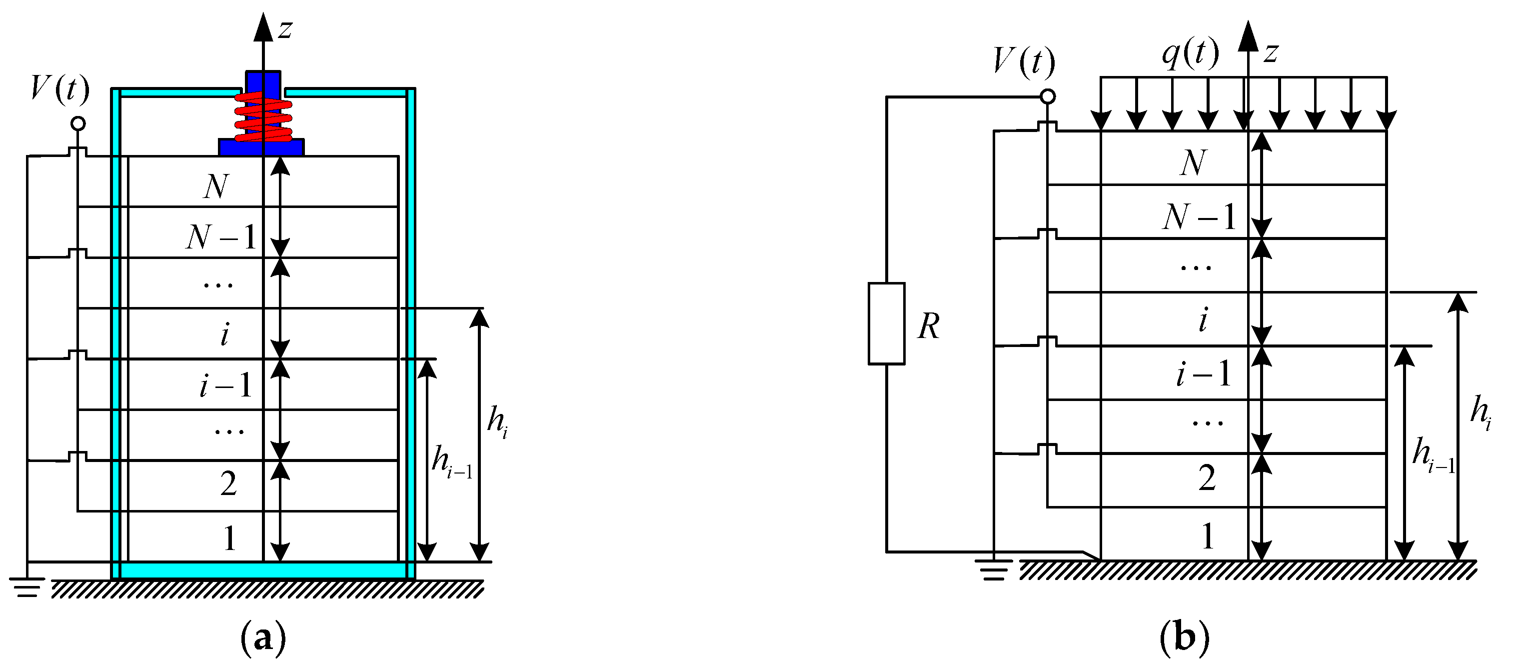
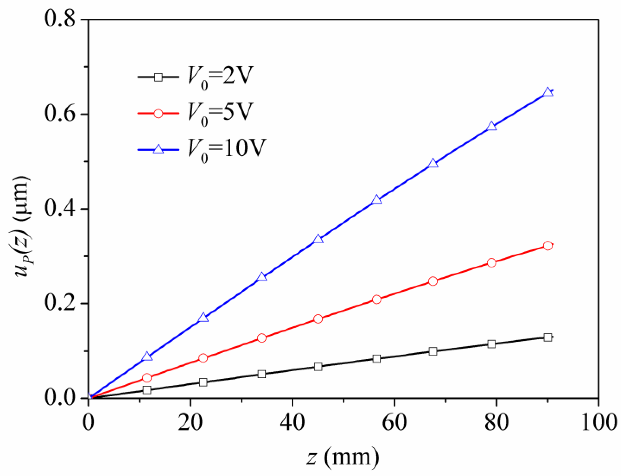
3.1. Model A: Piezoelectric Stack Subjected to a Voltage Load

Figure 1a is the schematic of a piezoelectric stack subjected to a voltage load. The mechanical and electrical boundary conditions and continuous conditions can be written as follows:
{ u P 1 | z = 0 = 0 σ z P N | z = h N = 1 S Z e x t u P N t  
{ ϕ i | z = h i 1 = 0 ,    ϕ i | z = h i = V ( t )     ( i = 1 , 3 , 5 , ) ϕ i | z = h i 1 = V ( t ) ,    ϕ i | z = h i = 0     ( i = 2 , 4 , 6 , )  
{ u P i | z = h i + = u P ( i + 1 ) | z = h i σ z P i | z = h i + = σ z P ( i + 1 ) | z = h i  
where Z e x t is the external impedance acting on the stack. The external impedance Z e x t can be expressed as [40]:
Z e x t = k s ω j + c s + m s j ω + m r o d j ω  
where k s , c s , m s are the equivalent spring stiffness, damping, and mass; and m r o d is the mass of the output rod. Combining Equations (6) and (8), the constant B P 1 in the first piezoelectric layer can be found as:
B P 1 = 0  
Combining Equations (6), (7), (9), and (10) gives:
{ A P i sin k P h i + B P i cos k P h i = A P ( i + 1 ) sin k P h i + B P ( i + 1 ) cos k P h i p P ( A P i cos k P h i B P i sin k P h i ) + e 33 2 κ 33 ε C 1 i = p P ( A P ( i + 1 ) cos k P h i B P ( i + 1 ) sin k P h i ) + e 33 2 κ 33 ε C 1 ( i + 1 )  
{ | e 33 | κ 33 ε ( A P i sin k P h i + B P i cos k P h i + C 1 i h i + C 0 i ) = V 0 ( i = 1 , 3 , 5 , ) | e 33 | κ 33 ε ( A P i sin k P h i 1 + B P i cos k P h i 1 + C 1 i h i 1 + C 0 i ) = 0 ( i = 1 , 3 , 5 , ) | e 33 | κ 33 ε ( A P i sin k P h i + B P i cos k P h i + C 1 i h i + C 0 i ) = 0 ( i = 2 , 4 , 6 , ) | e 33 | κ 33 ε ( A P i sin k P h i 1 + B P i cos k P h i 1 + C 1 i h i 1 + C 0 i ) = V 0 ( i = 2 , 4 , 6 , )
By solving Equations (13a,b), the following equations can be obtained:
{ A P i = δ i 1 A P 1 + λ i 1 V 0 B P i = δ i 2 A P 1 + λ i 2 V 0  
C 1 i = a i 1 A P i + b i 1 B P i + V i 1 V 0  
{ C 0 i = ( A P i sin k P h i 1 + B P i cos k P h i 1 + C 1 i h i 1 ) ( i = 1 , 3 , 5 , ) C 0 i = ( A P i sin k P h i + B P i cos k P h i + C 1 i h i ) ( i = 2 , 4 , 6 , )  
where
{ δ 1 1 = 1 δ 1 2 = 0 δ i + 1 1 = a i 6 δ i 1 + b i 6 δ i 2 δ i + 1 2 = a i 7 δ i 1 + b i 7 δ i 2 ,    { λ 1 1 = 0 λ 1 2 = 0 λ i + 1 1 = a i 6 λ i 1 + b i 6 λ i 2 + V i 4 λ i + 1 2 = a i 7 λ i 1 + b i 7 λ i 2 + V i 5  
{ a = e 33 2 p P κ 33 ε a i 1 = sin k P h i sin k P h i 1 h i h i 1 b i 1 = cos k P h i cos k P h i 1 h i h i 1 V i 1 = κ 33 ε | e 33 | ( h i h i 1 )  
{ a i 2 = 1 + a a i + 1 1 cos k P h i b i 2 = a b i + 1 1 cos k P h i a i 3 = 1 + a a i 1 cos k P h i b i 3 = a b i 1 cos k P h i V i 2 = a cos k P h i ( V i 1 V i + 1 1 )  
{ a i 4 = a a i + 1 1 sin k P h i b i 4 = 1 a b i + 1 1 sin k P h i a i 5 = a a i 1 sin k P h i b i 5 = 1 a b i 1 sin k P h i V i 3 = a sin k P h i ( V i + 1 1 V i 1 )  
{ H i 1 = a i 2 b i 4 b i 2 a i 4 a i 6 = ( a i 3 b i 4 a i 5 b i 2 ) / H i 1 b i 6 = ( b i 3 b i 4 b i 5 b i 2 ) / H i 1 V i 4 = ( V i 2 b i 4 V i 3 b i 2 ) / H i 1 a i 7 = ( a i 3 a i 4 a i 5 a i 2 ) / H i 1 b i 7 = ( b i 3 a i 4 b i 5 a i 2 ) / H i 1 V i 5 = ( V i 2 a i 4 V i 3 a i 2 ) / H i 1  
Substituting Equations (6), (7), (14), and (15) into Equation (8), A P 1 can be determined as:
A P 1 = d 0 V 0 d  
where
{ d 0 = ( 1 S Z e x t j ω λ N 1 λ N 2 p P ) sin k P h N + ( 1 S Z e x t j ω λ N 2 + λ N 1 p P ) cos k P h N     + e 33 2 κ 33 ε ( a N 1 λ N 1 + b N 1 λ N 2 + V N 1 ) d = ( 1 S Z e x t j ω δ N 1 δ N 2 p P ) sin k P h N + ( 1 S Z e x t j ω δ N 2 + δ N 1 p P ) cos k P h N     + e 33 2 κ 33 ε ( a N 1 δ N 1 + b N 1 δ N 2 )  
For Model A, the electrical admittance Y can be expressed as:
Y = 1 Z = I t o t a l V 0  
where Z is the electrical impedance and I t o t a l = j ω S | e 33 | i = 1 N C 1 i .

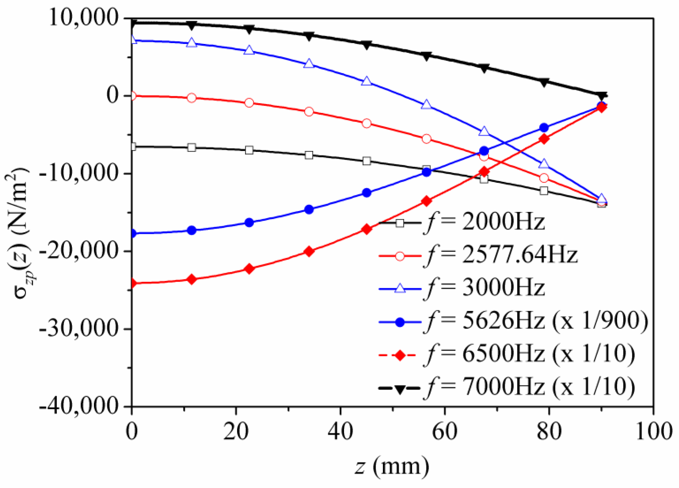
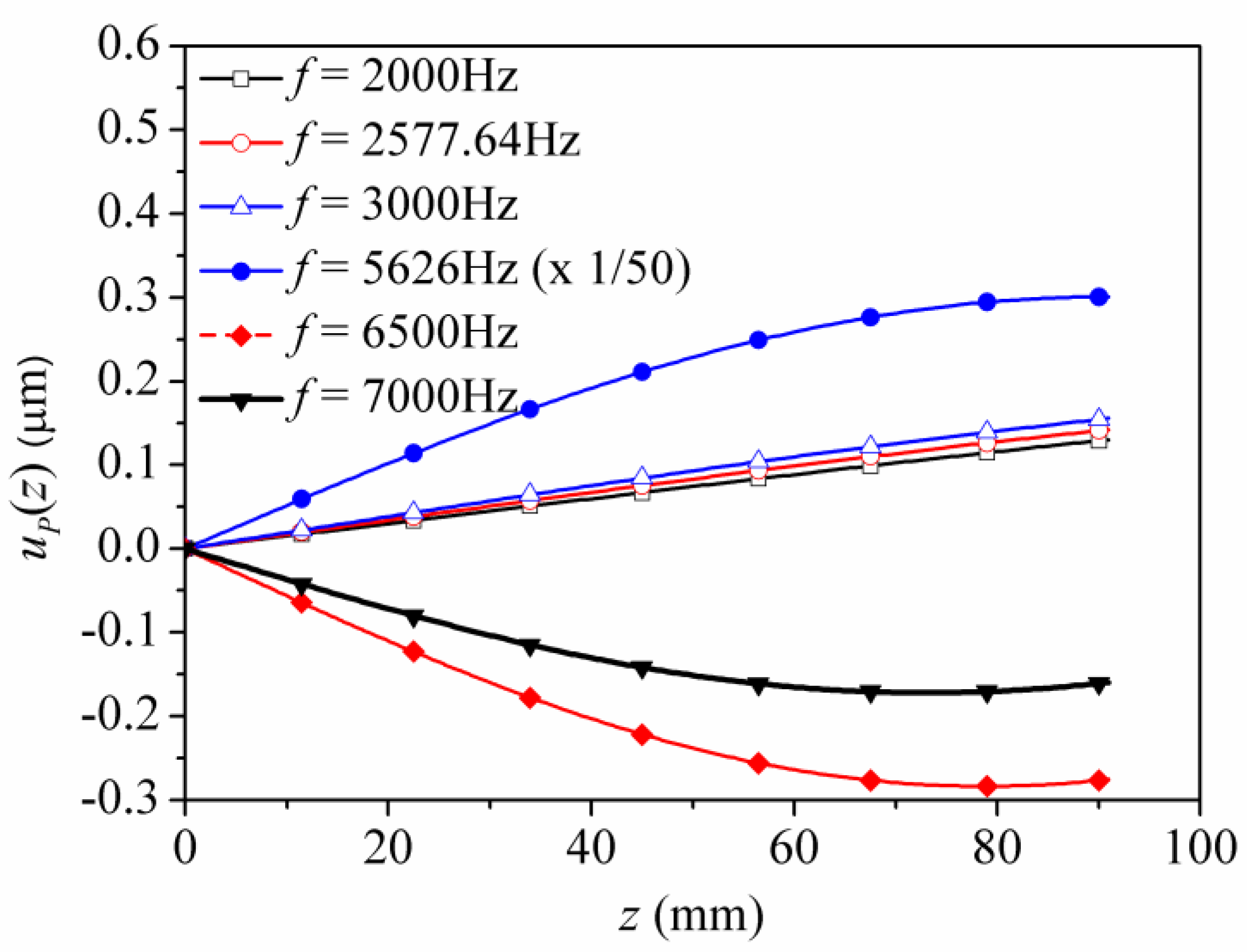
3.2. Model B: Piezoelectric Stack Subjected to a Uniformly Distributed Load

Figure 1b shows the configuration of a piezoelectric stack subjected to a uniformly distributed load. It should be noted that Equations (8), (9), (10), and (12)–(21) for Model A are still valid for Model B.
The mechanical and electrical boundary conditions in Model B can be given as:
σ z P N | z = h N = q ( t )  
V ( t ) = j R ω S | e 33 | i = 1 N C 1 i e j ω t = V 0 e j ω t  
where
V 0 = j R ω S | e 33 | i = 1 N C 1 i  
Combining Equations (14), (15), and (27), C 1 i can be obtained:
C 1 i = c i A P 1  
where c i can be determined using the following set of equations:
c i ( a i 1 λ i 1 + b i 1 λ i 2 + V i 1 ) j R ω S | e 33 | i = 1 N c i = a i 1 δ i 1 + b i 1 δ i 2    ( i = 1 , 2 , 3 , , N )  
Substituting Equations (7), (14), (27), and (28) into Equation (25), A P 1 can be determined to be:
A P 1 = q 0 d 1  
where
d 1 = p P [ ( δ N 1 + λ N 1 j R ω S | e 33 | i = 1 N c i ) cos k P h N     ( δ N 2 + λ N 2 j R ω S | e 33 | i = 1 N c i ) sin k P h N ] + e 33 2 κ 33 ε c N

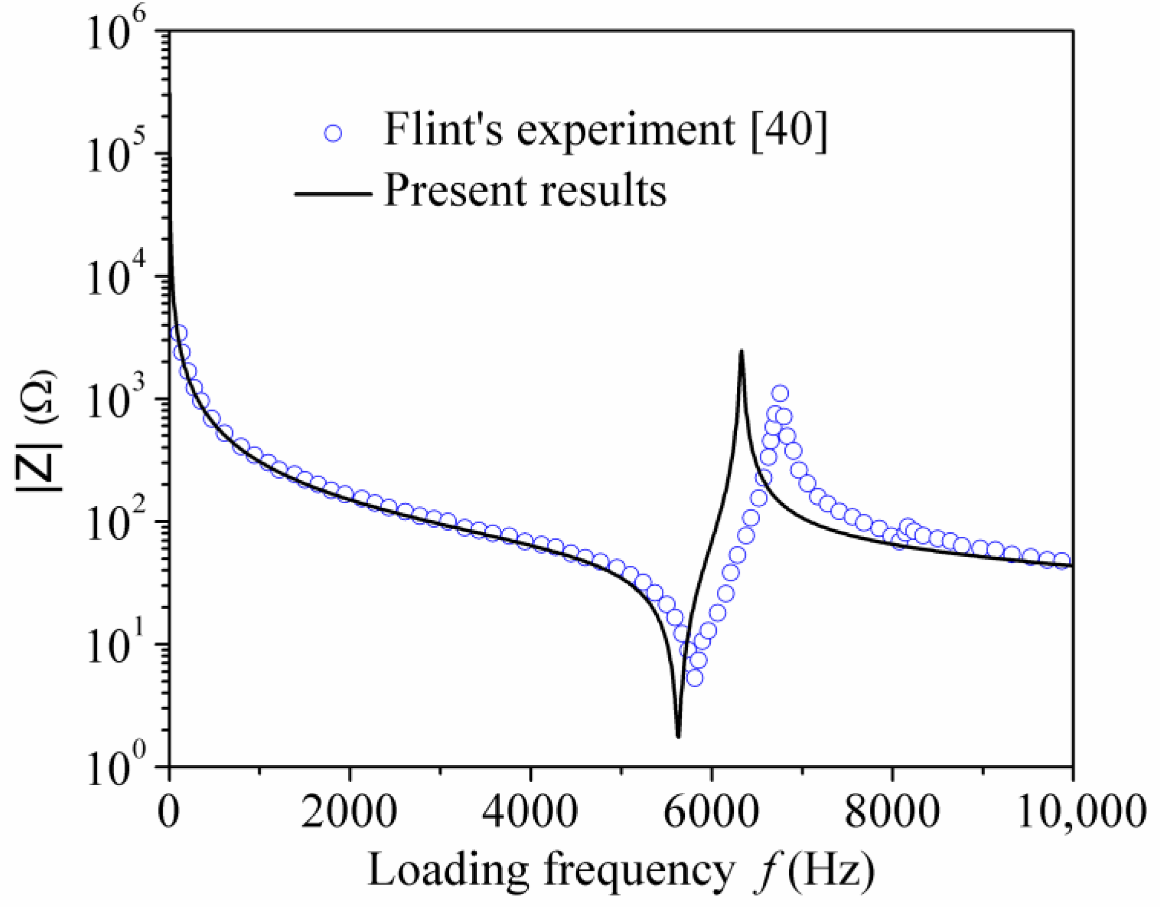
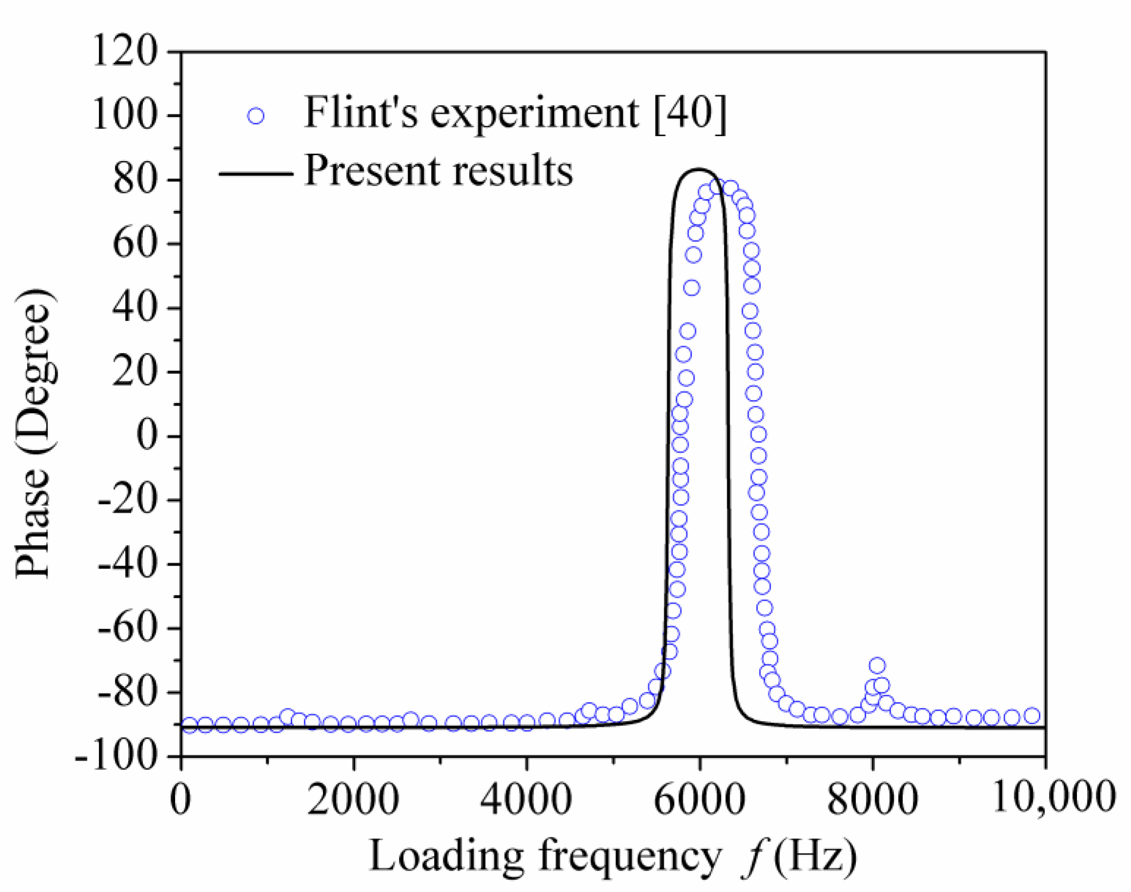
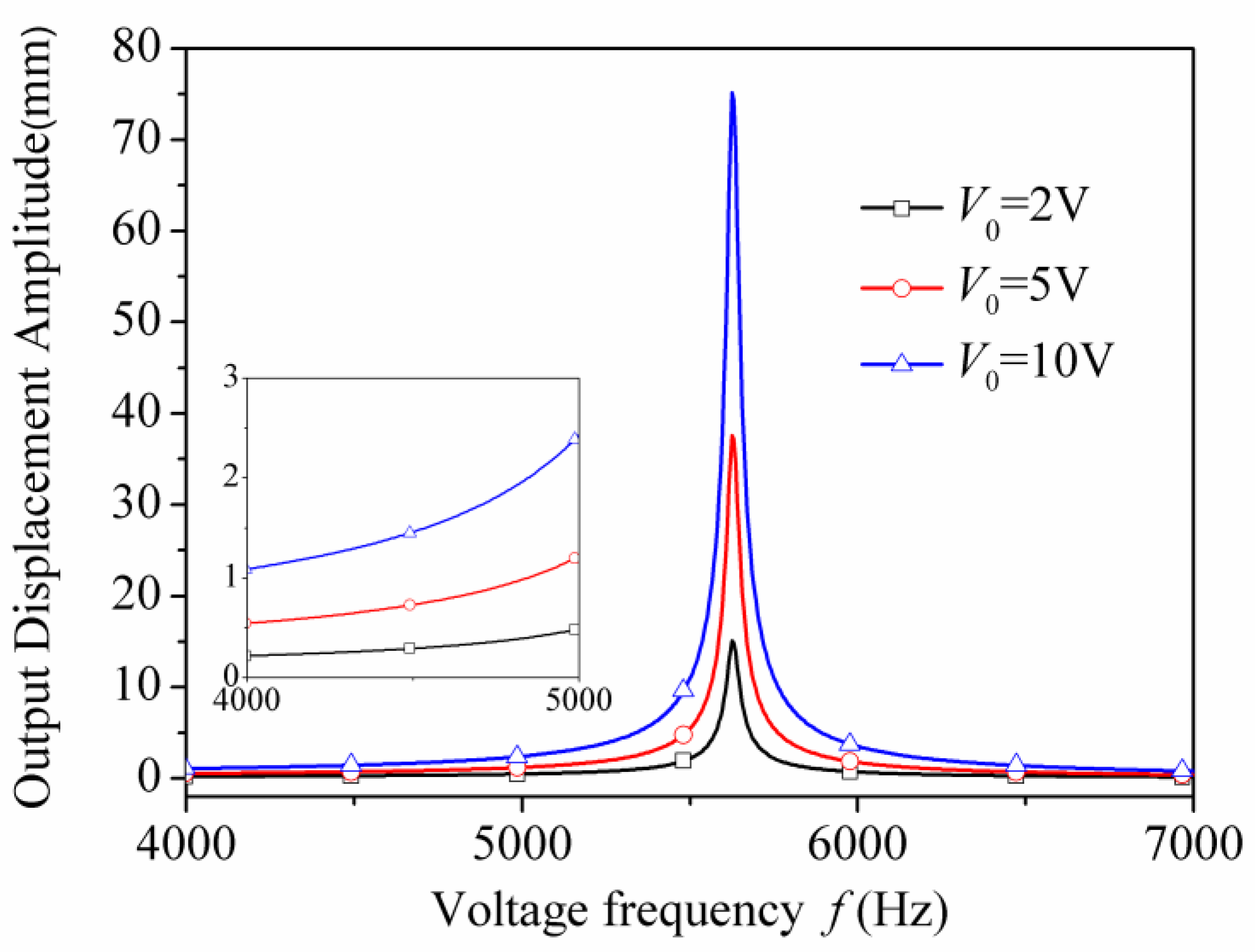
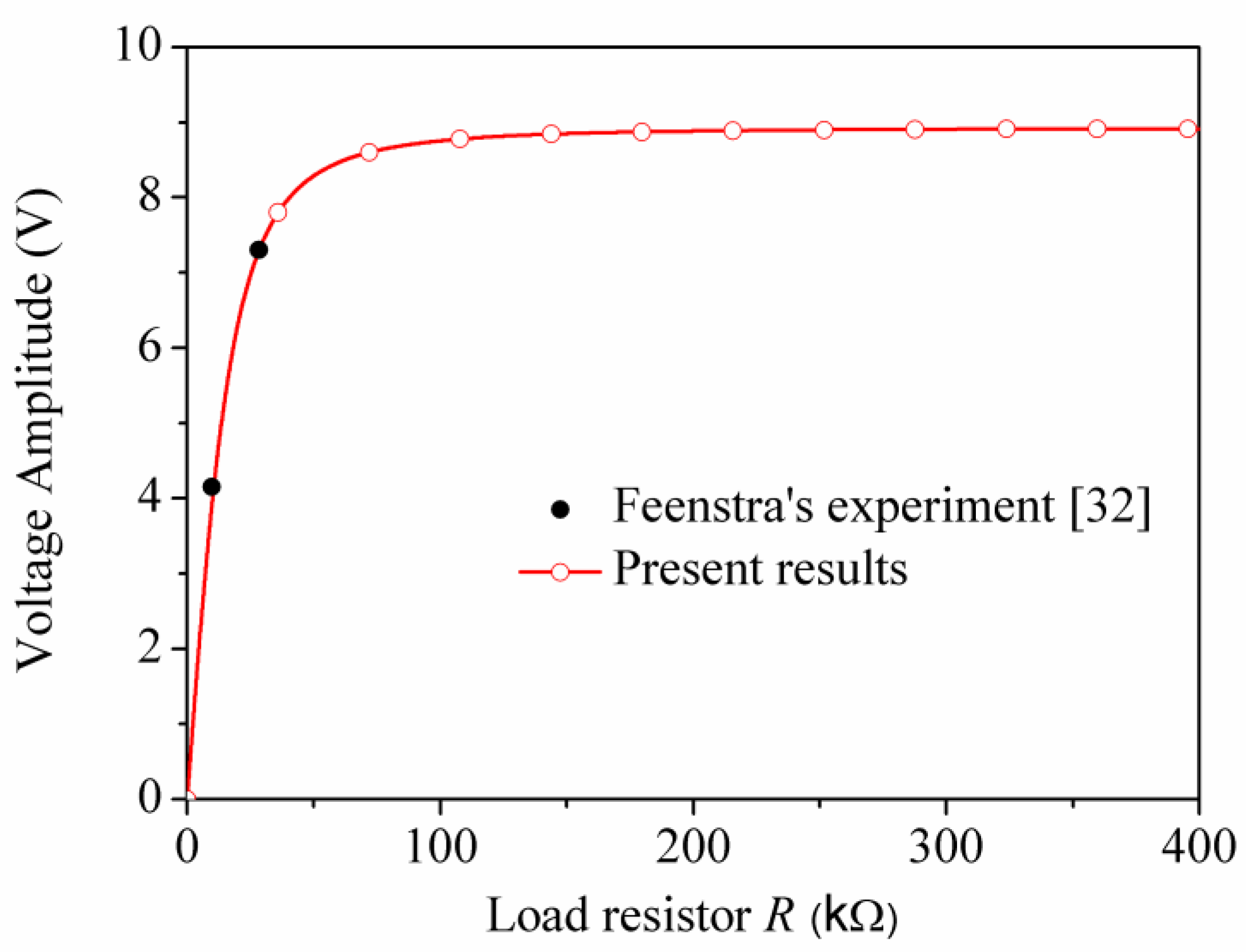
4. Comparison and Discussion

In the previous sections, the exact solutions of the mechanical components and electric components of piezoelectric stacks were obtained. In order to gain a comprehensive understanding, the present theoretical results are compared with experimental results from other investigations.
First, comparisons between the present theoretical results and experimental findings for a piezoelectric stack subjected to a voltage load were conducted. Flint et al. [40] conducted an experimental study on the electric-mechanical behavior of piezoelectric stack actuators. In their investigation, the Physik Instrumente P-245.70 type stack actuator was adopted, whose geometry information and material parameters can be found in Table 1. The number of total layers and the thickness of each layer in the stack are 182 and 0.5 mm, respectively. In the present analysis, the analytical model and the parameters of the stack used by Flint et al. [40] were adopted. Figure 2 and Figure 3 give the magnitude and phase of the coupled impedance changing with the loading frequency, respectively. In the calculation, the elastic constant C 33 P and the dielectric constant κ 33 σ are replaced with their complex forms, i.e., C 33 P * = C 33 P ( 1 + η m j ) and κ 33 σ * = κ 33 σ ( 1 + η e j ) , to take into account the mechanical and dielectric losses. Here, η m and η e are the mechanical and dielectric loss factors, as listed in Table 1. From Figure 2 and Figure 3, it can be found that the present analytical results match well with the experimental results for both the magnitude and phase of the coupled impedance. The difference is that the predicted resonance and anti-resonance frequencies are slightly lower than in the experimental data. Figure 4 gives the relationship between the output displacement amplitude and the external voltage frequency for different voltage amplitudes. It is obvious that the resonance frequency corresponds well with the above findings. In addition, the output displacement amplitude increases linearly with the increase of the external voltage amplitude.
When an external voltage with amplitude V 0 = 2   V is applied, Figure 5 and Figure 6 give the influence of the external voltage frequency on the distribution of stress σ z P ( z ) and displacement u P ( z ) along the axial direction, respectively. Here, it should be noted that when the voltage frequency is far from the resonance frequency, the mechanical loss, dielectric loss, as well as the spring damping can be neglected because their effects are very limited. Such an analysis is simpler and clearer for exhibiting the above mechanical components. However, when the voltage frequency is near the resonance frequency (fr = 5626 Hz), these factors need to be considered to avoid the singularity condition. In this case, the amplitudes of stress σ z P ( z ) and displacement u P ( z ) are addressed. In addition, some data are scaled down in these figures to better present the results within one graph. Figure 5 shows that the individual layers are either all compressed or all stretched at some frequencies. At some special frequencies, however, such as 3000 Hz, one part is compressed and the other is stretched. These two parts are divided by a nodal point, which is approximately z = 52 mm. Figure 6 shows that the individual layers can generate either all positive or all negative displacement u P ( z ) at some frequencies. In addition, from Figure 5 and Figure 6, it also can be found that the amplitudes of the stress σ z P ( z ) and displacement u P ( z ) will reach the maximum values near the resonance frequency. Figure 7 shows the influence of the voltage amplitude on the distribution of the displacement u P ( z ) along the axial direction with an external voltage frequency of f = 2000   Hz . It is clear that the displacement u P ( z ) changes linearly along the axial direction.
Second, comparisons between the present analytical results and the experimental results for a piezoelectric stack subjected to a uniformly distributed load were conducted. Feenstra et al. [32] performed experimental testing on the energy harvesting performance of a 130-layer mechanically amplified piezoelectric stack, whose geometric and material parameters can also be found in Table 1. The cross-section and total thickness of the stack are 25 mm2 and 16 mm, respectively. Figure 8 shows the voltage amplitude changing with the load resistor where the load frequency f = 5 Hz. It can be seen from Figure 8 that the present theoretical results correspond well with the experimental results of the voltage amplitude. Figure 8 also shows that as the load resistor increases, the voltage amplitude approaches a constant value. This constant is the open circuit voltage amplitude. Figure 9 shows the average power changing with the load resistor. It can be seen from Figure 9 that for a given load frequency, a matching load resistor can be determined whose value corresponds to the maximum average power. The matching load resistor decreases as the load frequency increases.

5. Conclusions

Based on the linear piezo-elasticity theory, an exact theoretical analysis for two different kinds of piezoelectric stacks was conducted, and the dynamic analytical solutions were derived using the displacement method. The present solutions were verified with other related experimental results in special cases. The present solutions can be used for the synthetical analysis of the mechanical behaviors and electrical characteristics of piezoelectric stack actuators and generators. Some conclusions can be drawn as follows:
For the piezoelectric stack actuator, it was found that: (1) the output displacement amplitude increases linearly with the increase of the external voltage amplitude; (2) the individual layers are either all compressed or all stretched at some frequencies, while at some special frequencies there is a nodal point that divides the actuator into the compressed and stretched parts; and (3) the individual layers can generate either all positive or all negative displacement u P ( z ) at some frequencies. In addition, the generated amplitudes of stress σ z P ( z ) and displacement u P ( z ) can reach the maximum values near the resonance frequency.
For the piezoelectric stack generator, it was found that: (1) the voltage amplitude approaches the open circuit voltage amplitude with the increase of the load resistor; (2) the matching load resistor can be determined to be the resistance corresponding to the maximum average power, and the matching load resistor decreases as the load frequency increases.

Author Contributions

Original work (J.W. and X.L.); J.W. and X.L. established the modeling and performed the numerical analysis; J.W. and X.L. wrote the paper; W.L. edited and polished the paper; J.W., X.L., and W.L. carried out the revision.

Funding

This work is supported by the National Natural Science Foundation of China (51708025) and the Fundamental Research Funds for the Central Universities (FRF-TP-16-069A1).

Conflicts of Interest

The authors declare no conflict of interest.

References

  1. Dubus, B.; Haw, G.; Granger, C.; Ledez, O. Characterization of multilayered piezoelectric ceramics for high power transducers. Ultrasonics 2002, 40, 903–906. [Google Scholar] [CrossRef]
  2. Yao, K.; Uchino, K.; Xu, Y.; Dong, S.; Lim, L.C. Compact piezoelectric stacked actuators for high power applications. IEEE Trans. Ultrason. Ferroelectr. Freq. Control 2000, 47, 819–825. [Google Scholar] [PubMed]
  3. Sasaki, Y.; Umeda, M.; Takahashi, S.; Yamamoto, M.; Ochi, A.; Inoue, T. High-power characteristics of multilayer piezoelectric ceramic transducers. Jpn. J. Appl. Phys. 2001, 40, 5743–5746. [Google Scholar] [CrossRef]
  4. Xiang, H.J.; Shi, Z.F. Static analysis for multi-layered piezoelectric cantilevers. Int. J. Solids Struct. 2008, 45, 113–128. [Google Scholar] [CrossRef]
  5. Yang, Z.T.; Yang, J.S. Connected vibrating piezoelectric bimorph beams as a wide-band piezoelectric power harvester. J. Intell. Mater. Syst. Struct. 2009, 20, 569–574. [Google Scholar] [CrossRef]
  6. Xiang, H.J.; Shi, Z.F. Static analysis of a multilayer piezoelectric actuator with bonding layers and electrodes. Smart Struct. Syst. 2009, 5, 547–564. [Google Scholar] [CrossRef]
  7. Tang, L.; Yang, Y. A multiple-degree-of-freedom piezoelectric energy harvesting model. J. Intell. Mater. Syst. Struct. 2012, 23, 1631–1647. [Google Scholar] [CrossRef]
  8. Tang, L.; Zhao, L.; Yang, Y.; Lefeuvre, E. Equivalent circuit representation and analysis of galloping-based wind energy harvesting. IEEE/ASME Trans. Mechatron. 2014, 20, 834–844. [Google Scholar] [CrossRef]
  9. Yang, Y.; Zhao, L.; Tang, L. Comparative study of tip cross-sections for efficient galloping energy harvesting. Appl. Phys. Lett. 2013, 102, 064105. [Google Scholar] [CrossRef]
  10. Lim, C.W.; Chen, W.Q.; Zeng, Q.C. Exact solution for thick, laminated piezoelectric beams. Mech. Adv. Mater. Struct. 2007, 14, 81–87. [Google Scholar] [CrossRef]
  11. Shi, Z.F.; Zhao, S. The resonance frequency of laminated piezoelectric rectangular plates. IEEE Trans. Ultrason. Ferroelectr. Freq. Control 2011, 58, 623–628. [Google Scholar] [PubMed]
  12. Cheng, Z.Q.; Lim, C.W.; Kitipornchai, S. Three-dimensional asymptotic approach to inhomogeneous and laminated piezoelectric plates. Int. J. Solids Struct. 2000, 37, 3153–3175. [Google Scholar] [CrossRef]
  13. Xu, D.Y.; Cheng, X.; Huang, S.F.; Jiang, M.H. Electromechanical properties of 2-2 cement based piezoelectric composite. Curr. Appl. Phys. 2009, 9, 816–819. [Google Scholar] [CrossRef]
  14. Xu, D.Y.; Cheng, X.; Huang, S.F.; Jiang, M.H. Effect of cement matrix and composite thickness on properties of 2-2 type cement-based piezoelectric composites. J. Compos. Mater. 2011, 45, 2083–2089. [Google Scholar]
  15. Zhang, T.T. Theoretical analyses for a 2-2 cement-based piezoelectric curved composite with electrode layers. Smart Struct. Syst. 2014, 14, 961–980. [Google Scholar] [CrossRef]
  16. Zhang, T.T.; Dong, S.; Liu, W. The dynamic characteristics of 2-2 cement-based piezoelectric composite with electrode layers. Mater. Res. Innov. 2015, 19. S9-181-S189-186. [Google Scholar] [CrossRef]
  17. Zhang, T.T.; Liao, Y.; Zhang, K.; Chen, J. Theoretical analysis of the dynamic properties of a 2-2 cement-based piezoelectric dual-layer stacked sensor under impact load. Sensors 2017, 17, 1019. [Google Scholar] [CrossRef] [PubMed]
  18. Zhang, T.T.; Zhang, K.; Liu, W.; Liao, Y. Impact mechanical response of a 2-2 cement-based piezoelectric sensor considering the electrode layer effect. Sensors 2017, 17, 2035. [Google Scholar] [CrossRef]
  19. Wang, L.; Qin, L.; Li, W.; Zhang, B.; Lu, Y.; Li, G. Analysis on radial vibration of a stack of piezoelectric shells. Ceram. Int. 2015, 41, S856–S860. [Google Scholar] [CrossRef]
  20. Wang, J.J.; Wei, P.; Qin, L.; Tang, L. Modeling and analysis of multilayer piezoelectric-elastic spherical transducers. J. Intell. Mater. Syst. Struct. 2018, 29, 2437–2455. [Google Scholar] [CrossRef]
  21. Lee, D.G.; Or, S.W.; Carman, G.P. Design of a piezoelectric-hydraulic pump with active valves. J. Intell. Mater. Syst. Struct. 2004, 15, 107–115. [Google Scholar] [CrossRef]
  22. Li, J.; Sedaghati, R.; Dargahi, J.; Waechter, D. Design and development of a new piezoelectric linear inchworm® actuator. Mechatronics 2005, 15, 651–681. [Google Scholar] [CrossRef]
  23. Tolliver, L.; Xu, T.B.; Jiang, X. Finite element analysis of the piezoelectric stacked-hybats transducer. Smart Mater. Struct. 2013, 22, 035015. [Google Scholar] [CrossRef]
  24. Liu, J.; Liu, Y.; Zhao, L.; Xu, D.; Chen, W.; Deng, J. Design and experiments of a single-foot linear piezoelectric actuator operated in stepping mode. IEEE Trans. Ind. Electron. 2018, 65, 8063–8071. [Google Scholar] [CrossRef]
  25. Liu, Y.; Yan, J.; Xu, D.; Chen, W.; Yang, X.; Tian, X. An i-shape linear piezoelectric actuator using resonant type longitudinal vibration transducers. Mechatronics 2016, 40, 87–95. [Google Scholar] [CrossRef]
  26. Shao, S.; Shi, S.; Chen, W.; Liu, J.; Liu, Y. Research on a linear piezoelectric actuator using t-shape transducer to realize high mechanical output. Appl. Sci. 2016, 6, 103. [Google Scholar] [CrossRef]
  27. Zhao, S.; Erturk, A. Deterministic and band-limited stochastic energy harvesting from uniaxial excitation of a multilayer piezoelectric stack. Sens. Actuators A 2014, 214, 58–65. [Google Scholar] [CrossRef]
  28. Zhao, S.; Erturk, A. Energy harvesting from harmonic and noise excitation of multilayer piezoelectric stacks: Modeling and experiment. Act. Passive Electron. Compon. 2013, 8688, 86881Q. [Google Scholar]
  29. Sun, C.; Shang, G.; Zhu, X.; Tao, Y.; Li, Z. Modeling for Piezoelectric Stacks in Series and Parallel. In Proceedings of the 2013 Third International Conference on Intelligent System Design and Engineering Applications (ISDEA), Hongkong, China, 16–18 January 2013; IEEE: Piscataway, NJ, USA, 2013; pp. 954–957. [Google Scholar]
  30. Xu, T.B.; Siochi, E.J.; Kang, J.H.; Zuo, L.; Zhou, W.; Tang, X.; Jiang, X. Energy harvesting using a PZT ceramic multilayer stack. Smart Mater. Struct. 2013, 22, 065015. [Google Scholar] [CrossRef]
  31. Lee, A.J.; Wang, Y.; Inman, D.J. Energy harvesting of piezoelectric stack actuator from a shock event. J. Vib. Acoust. 2014, 136, 011016. [Google Scholar] [CrossRef]
  32. Feenstra, J.; Granstrom, J.; Sodano, H.A. Energy harvesting through a backpack employing a mechanically amplified piezoelectric stack. Mech. Syst. Signal Process. 2008, 22, 721–734. [Google Scholar] [CrossRef]
  33. Platt, S.R.; Farritor, S.; Haider, H. On low-frequency electric power generation with PZT ceramics. IEEE/ASME Trans. Mechatron. 2005, 10, 240–252. [Google Scholar] [CrossRef]
  34. Almouahed, S.; Gouriou, M.; Hamitouche, C.; Stindel, E.; Roux, C. The use of piezoceramics as electrical energy harvesters within instrumented knee implant during walking. IEEE/ASME Trans. Mech. 2011, 16, 799–807. [Google Scholar] [CrossRef]
  35. Zhang, Y.K.; Lu, T.F.; Peng, Y. Three-port equivalent circuit of multi-layer piezoelectric stack. Sens. Actuators A 2015, 236, 92–97. [Google Scholar] [CrossRef]
  36. Lin, S.; Xu, J. Effect of the matching circuit on the electromechanical characteristics of sandwiched piezoelectric transducers. Sensors 2017, 17, 329. [Google Scholar] [CrossRef] [PubMed]
  37. Lin, S. Study on the parallel electric matching of high power piezoelectric transducers. Acta Acust. United Acust. 2017, 103, 385–391. [Google Scholar] [CrossRef]
  38. Lin, S. Effect of electric load impedances on the performance of sandwich piezoelectric transducers. IEEE Trans. Ultrason. Ferroelectr. Freq. Control 2004, 51, 1280–1286. [Google Scholar] [PubMed]
  39. Kim, S. Low Power Energy Harvesting with Piezoelectric Generators. Ph.D. Thesis, University of Pittsburgh, Pittsburgh, PA, USA, 2002. [Google Scholar]
  40. Flint, E.M.; Liang, C.; Rogers, C.A. Electromechanical analysis of piezoelectric stack active member power consumption. J. Intell. Mater. Syst. Struct. 1995, 6, 117–124. [Google Scholar] [CrossRef]
  41. Zhang, Y.K.; Lu, T.F.; Al-Sarawi, S. Formulation of a simple distributed-parameter model of multilayer piezoelectric actuators. J. Intell. Mater. Syst. Struct. 2016, 27, 1485–1491. [Google Scholar] [CrossRef]
  42. Zhang, Y.K.; Tu, Z.; Lu, T.F.; Al-Sarawi, S. A simplified transfer matrix of multi-layer piezoelectric stack. J. Intell. Mater. Syst. Struct. 2017, 28, 595–603. [Google Scholar] [CrossRef]
  43. Qian, F.; Xu, T.B.; Zuo, L. Design, optimization, modeling and testing of a piezoelectric footwear energy harvester. Energy Convers. Manag. 2018, 171, 1352–1364. [Google Scholar] [CrossRef]
  44. Wang, J.J.; Shi, Z.F.; Xiang, H.J.; Song, G. Modeling on energy harvesting from a railway system using piezoelectric transducers. Smart Mater. Struct. 2015, 24, 105017. [Google Scholar] [CrossRef]
  45. Jiang, X.; Li, Y.; Li, J.; Wang, J.; Yao, J. Piezoelectric energy harvesting from traffic-induced pavement vibrations. J. Renew. Sustain. Energy 2014, 6, 043110. [Google Scholar] [CrossRef] [Green Version]
  46. Senousy, M.; Li, F.; Mumford, D.; Gadala, M.; Rajapakse, N. Thermo-electro-mechanical performance of piezoelectric stack actuators for fuel injector applications. J. Intell. Mater. Syst. Struct. 2008, 20, 387–399. [Google Scholar] [CrossRef]
  47. Senousy, M.S.; Rajapakse, R.K.N.D.; Mumford, D.; Gadala, M.S. Self-heat generation in piezoelectric stack actuators used in fuel injectors. Smart Mater. Struct. 2009, 18, 045008. [Google Scholar] [CrossRef]
  48. Arnold, F.J.; Bravo-Roger, L.L.; Gonçalves, M.S.; Grilo, M. Characterization of sandwiched piezoelectric transducers-a complement for teaching electric circuits. Lat. Am. J. Phys. Educ. 2012, 6, 216–220. [Google Scholar]
  49. Arnold, F.J.; Mühlen, S.S. The resonance frequencies on mechanically pre-stressed ultrasonic piezotransducers. Ultrasonics 2001, 39, 1–5. [Google Scholar] [CrossRef]
  50. Arnold, F.J.; Mühlen, S.S. The mechanical pre-stressing in ultrasonic piezotransducers. Ultrasonics 2001, 39, 7–11. [Google Scholar] [CrossRef]
  51. Zhang, T.T.; Shi, Z.F. Two-dimensional exact analysis for piezoelectric curved actuators. J. Micromech. Microeng. 2006, 16, 640–647. [Google Scholar] [CrossRef]
  52. Zhang, T.T.; Shi, Z.F. Bending behavior of 2-2 multi-layered piezoelectric curved actuators. Smart Mater. Struct. 2007, 16, 634–641. [Google Scholar] [CrossRef]
  53. Zhang, T.T.; Shi, Z.F. Exact analysis of the dynamic properties of a 2-2 cement based piezoelectric transducer. Smart Mater. Struct. 2011, 20, 085017. [Google Scholar] [CrossRef]
  54. Huang, D.J.; Ding, H.J.; Chen, W.Q. Piezoelasticity solutions for functionally graded piezoelectric beams. Smart Mater. Struct. 2007, 16, 687–695. [Google Scholar] [CrossRef]
  55. Huang, D.J.; Ding, H.J.; Chen, W.Q. Analysis of functionally graded and laminated piezoelectric cantilever actuators subjected to constant voltage. Smart Mater. Struct. 2008, 17, 065002. [Google Scholar] [CrossRef]
  56. Chen, W.Q.; Ding, H.J.; Xu, R.Q. Three-dimensional static analysis of multi-layered piezoelectric hollow spheres via the state space method. Int. J. Solids Struct. 2001, 38, 4921–4936. [Google Scholar] [CrossRef]
  57. Duggen, L.; Willatzen, M.; Lassen, B. Crystal orientation effects on the piezoelectric field of strained zinc-blende quantum-well structures. Phys. Rev. B 2008, 78, 205323. [Google Scholar] [CrossRef]
  58. Auld, B.A. Acoustic Fields and Waves in Solids; Wiley: New York, NY, USA, 1973. [Google Scholar]
  59. Duggen, L.; Willatzen, M. Crystal orientation effects on wurtzite quantum well electromechanical fields. Phys. Rev. B 2010, 82, 205303. [Google Scholar] [CrossRef]
  60. Duggen, L.; Willatzen, M. Acousto-optical phonon excitation in piezoelectric wurtzite slabs and crystal growth orientation effects. Semicond. Sci. Technol. 2017, 32, 064001. [Google Scholar] [CrossRef]
  61. Duggen, L.; Willatzen, M. Acousto-optical phonon excitation in cubic piezoelectric slabs and crystal growth orientation effects. Phys. Rev. B 2017, 95, 035310. [Google Scholar] [CrossRef]
Figure 1. Schematic of the piezoelectric stack: (a) under a voltage load (Model A) and (b) under a uniformly distributed load (Model B).
Applsci 08 01779 g001
Figure 2. Magnitude of coupled impedance versus loading frequency.
Applsci 08 01779 g002
Figure 3. Phase of coupled impedance versus loading frequency.
Applsci 08 01779 g003
Figure 4. Relationship between the voltage frequency and the output displacement amplitude for different voltage amplitudes.
Applsci 08 01779 g004
Figure 5. Influence of the voltage frequency on the distribution of stress σ z P ( z ) along the axial direction with V 0 = 2   V .
Applsci 08 01779 g005
Figure 6. Influence of the voltage frequency on the distribution of displacement u P ( z ) along the axial direction with V 0 = 2   V .
Applsci 08 01779 g006
Figure 7. Influence of the voltage amplitude on the distribution of displacement u P ( z ) along the axial direction with voltage frequency f = 2000   Hz .
Applsci 08 01779 g007
Figure 8. The voltage amplitude changes with the load resistor.
Applsci 08 01779 g008
Figure 9. The average power changes with the load resistor.
Applsci 08 01779 g009
Table 1. Geometric and material parameters of the piezoelectric stack.
ParametersSymbolActuator [40]Generator [32]
Elastic constant (elastic modulus) C 33 P   ( × 10 9 N / m 2 ) 32.744
Piezoelectric constant d 33   ( × 10 12 C / N ) 427650
Dielectric constant κ 33 σ / ε 0 (nF/m)22036802
Density ρ P (kg/m2)78005750
Number of layersN182130
Layer thickness h P (mm)0.50.123
Stack areaS (mm2)78.525
Stack lengthL (mm)9116
Spring stiffness k s ( × 10 6 N / m 2 ) 9.66~
Spring damping c s 0.01~
Spring mass m s (g)7.3~
Output rod mass m r o d (g)0.4~
Mechanical loss factor η m 8.33 × 10⁻³~
Dielectric loss factor η e 15 × 10−3~
ε 0 = 8.85 × 10 12 F / m , permittivity of free space.

