Electrically Tunable Hydrogen-Bonded Liquid Crystal Phase Control Device

Abstract
:1. Introduction
2. Materials and Methods
3. Results and Discussions
4. Conclusions
Author Contributions
Funding
Conflicts of Interest
References
- Tonouchi, M. Cutting-edge terahertz technology. Nat. Photonics 2007, 1, 97–105. [Google Scholar] [CrossRef]
- Scherger, B.; Jördens, C.; Koch, M. Variable-focus terahertz lens. Opt. Express 2011, 19, 4528–4535. [Google Scholar] [CrossRef] [PubMed]
- Monnai, Y.; Altmann, K.; Jansen, C.; Hillmer, H.; Koch, M.; Shinoda, H. Terahertz beam steering and variable focusing using programmable diffraction gratings. Opt. Express 2013, 21, 2347–2354. [Google Scholar] [CrossRef] [PubMed]
- Shalaby, M.; Peccianti, M.; Ozturk, Y.; Clerici, M.; Al-Naib, I.; Razzari, L.; Ozaki, T.; Mazhorova, A.; Skorobogatiy, M.; Morandotti, R. Terahertz Faraday rotation in a magnetic liquid: High magneto-optical figure of merit and broadband operation in a ferrofluid. Appl. Phys. Lett. 2012, 100, 241107. [Google Scholar] [CrossRef]
- Ma, F.; Lin, Y.-S.; Zhang, X.; Lee, C. Tunable multiband terahertz metamaterials using a reconfigurable electric split-ring resonator array. Light Sci. Appl. 2014, 3, e171. [Google Scholar] [CrossRef]
- Bludov, Y.V.; Vasilevskiy, M.I.; Peres, N.M.R. Tunable graphene-based polarizer. J. Appl. Phys. 2012, 112, 084320. [Google Scholar] [CrossRef] [Green Version]
- Busch, S.F.; Schumann, S.; Jansen, C.; Scheller, M.; Koch, M.; Fischer, B.M. Optically gated tunable terahertz filters. Appl. Phys. Lett. 2012, 100, 261109. [Google Scholar] [CrossRef]
- Nose, T.; Sato, S.; Mizuno, K.; Bae, J.; Nozokido, T. Refractive index of nematic liquid crystals in the submillimeter wave region. Appl. Opt. 1997, 36, 6383–6387. [Google Scholar] [CrossRef]
- Turchinovich, D.; Knobloch, P.; Luessem, G.; Koch, M. THz time-domain spectroscopy on 4-(trans-4′-pentylcyclohexyl)-benzonitril. In Liquid Crystals V; International Society for Optics and Photonics: Bellingham, WA, USA, 2001; Volume 4463, pp. 65–71. [Google Scholar]
- Wilk, R.; Vieweg, N.; Kopschinski, O.; Hasek, T.; Koch, M. THz Spectroscopy of Liquid Crystals from the CB Family. J. Infrared Millim. Terahertz Waves 2009, 30, 1139–1147. [Google Scholar] [CrossRef]
- Vieweg, N.; Koch, M. Terahertz properties of liquid crystals with negative dielectric anisotropy. Appl. Opt. 2010, 49, 5764–5767. [Google Scholar] [CrossRef] [PubMed]
- Vieweg, N.; Shakfa, M.K.; Koch, M. BL037: A nematic mixture with high terahertz birefringence. Opt. Commun. 2011, 284, 1887–1889. [Google Scholar] [CrossRef]
- Vieweg, N.; Fischer, B.M.; Reuter, M.; Kula, P.; Dabrowski, R.; Celik, M.A.; Frenking, G.; Koch, M.; Jepsen, P.U. Ultrabroadband terahertz spectroscopy of a liquid crystal. Opt. Express 2012, 20, 28249–28256. [Google Scholar] [CrossRef] [Green Version]
- Reuter, M.; Vieweg, N.; Fischer, B.M.; Mikulicz, M.; Koch, M.; Garbat, K.; Dąbrowski, R. Highly birefringent, low-loss liquid crystals for terahertz applications. APL Mater. 2013, 1, 012107. [Google Scholar] [CrossRef] [Green Version]
- Wilk, R.; Vieweg, N.; Kopschinski, O.; Koch, M. Liquid crystal based electrically switchable Bragg structure for THz waves. Opt. Express 2009, 17, 7377–7382. [Google Scholar] [CrossRef] [PubMed]
- Vieweg, N.; Born, N.; Al-Naib, I.; Koch, M. Electrically Tunable Terahertz Notch Filters. J. Infrared Millim. Terahertz Waves 2012, 33, 327–332. [Google Scholar] [CrossRef]
- Altmann, K.; Reuter, M.; Garbat, K.; Koch, M.; Dabrowski, R.; Dierking, I. Polymer stabilized liquid crystal phase shifter for terahertz waves. Opt. Express 2013, 21, 12395–12400. [Google Scholar] [CrossRef] [PubMed]
- Tsai, T.-R.; Chen, C.-Y.; Pan, C.-L.; Pan, R.-P.; Zhang, X.-C. Terahertz time-domain spectroscopy studies of the optical constants of the nematic liquid crystal 5CB. Appl. Opt. 2003, 42, 2372–2376. [Google Scholar] [CrossRef]
- Pan, R.-P.; Tsai, T.-R.; Chen, C.-Y.; Wang, C.-H.; Pan, C.-L. The Refractive Indices of Nematic Liquid Crystal 4′-n-pentyl-4-cyanobiphenyl in the THz Frequency Range. Mol. Cryst. Liq. Cryst. 2004, 409, 137–144. [Google Scholar] [CrossRef]
- Pan, R.-P.; Hsieh, C.-F.; Pan, C.-L.; Chen, C.-Y. Temperature-dependent optical constants and birefringence of nematic liquid crystal 5CB in the terahertz frequency range. J. Appl. Phys. 2008, 103, 093523. [Google Scholar] [CrossRef]
- Tang, T.-T.; Pan, R.-P.; Wang, Y.-C.; Pan, C.-L. THz Time-Domain Spectroscopic Studies of a Ferroelectric Liquid Crystal in the SmA* and SmC* Phases. Ferroelectrics 2008, 364, 72–77. [Google Scholar] [CrossRef]
- Yang, C.-S.; Lin, C.-J.; Pan, R.-P.; Que, C.T.; Yamamoto, K.; Tani, M.; Pan, C.-L. The complex refractive indices of the liquid crystal mixture E7 in the terahertz frequency range. J. Opt. Soc. Am. B 2010, 27, 1866–1873. [Google Scholar] [CrossRef]
- Chen, C.-Y.; Tsai, T.-R.; Pan, C.-L.; Pan, R.-P. Room temperature terahertz phase shifter based on magnetically controlled birefringence in liquid crystals. Appl. Phys. Lett. 2003, 83, 4497–4499. [Google Scholar] [CrossRef]
- Chen, C.-Y.; Hsieh, C.-F.; Lin, Y.-F.; Pan, R.-P.; Pan, C.-L. Magnetically tunable room-temperature 2π liquid crystal terahertz phase shifter. Opt. Express 2004, 12, 2625–2630. [Google Scholar] [CrossRef] [PubMed]
- Hsieh, C.-F.; Pan, R.-P.; Tang, T.-T.; Chen, H.-L.; Pan, C.-L. Voltage-controlled liquid-crystal terahertz phase shifter and quarter-wave plate. Opt. Lett. 2006, 31, 1112–1114. [Google Scholar] [CrossRef] [PubMed]
- Ho, I.-C.; Pan, C.-L.; Hsieh, C.-F.; Pan, R.-P. Liquid-crystal-based terahertz tunable Solc filter. Opt. Lett. 2008, 33, 1401–1403. [Google Scholar] [CrossRef] [PubMed]
- Lin, C.-J.; Li, Y.-T.; Hsieh, C.-F.; Pan, R.-P.; Pan, C.-L. Manipulating terahertz wave by a magnetically tunable liquid crystal phase grating. Opt. Express 2008, 16, 2995–3001. [Google Scholar] [CrossRef] [PubMed]
- Yang, C.-S.; Tang, T.-T.; Chen, P.-H.; Pan, R.-P.; Yu, P.; Pan, C.-L. Voltage-controlled liquid-crystal terahertz phase shifter with indium–tin–oxide nanowhiskers as transparent electrodes. Opt. Lett. 2014, 39, 2511–2513. [Google Scholar] [CrossRef] [PubMed]
- Wang, L.; Lin, X.-W.; Hu, W.; Shao, G.-H.; Chen, P.; Liang, L.-J.; Jin, B.-B.; Wu, P.-H.; Qian, H.; Lu, Y.-N.; et al. Broadband tunable liquid crystal terahertz waveplates driven with porous graphene electrodes. Light Sci. Appl. 2015, 4, e253. [Google Scholar] [CrossRef]
- OSA. Tunable Reflective Liquid Crystal Terahertz Waveplates. Available online: https://www.osapublishing.org/ome/abstract.cfm?uri=ome-7-6-2023 (accessed on 13 November 2018).
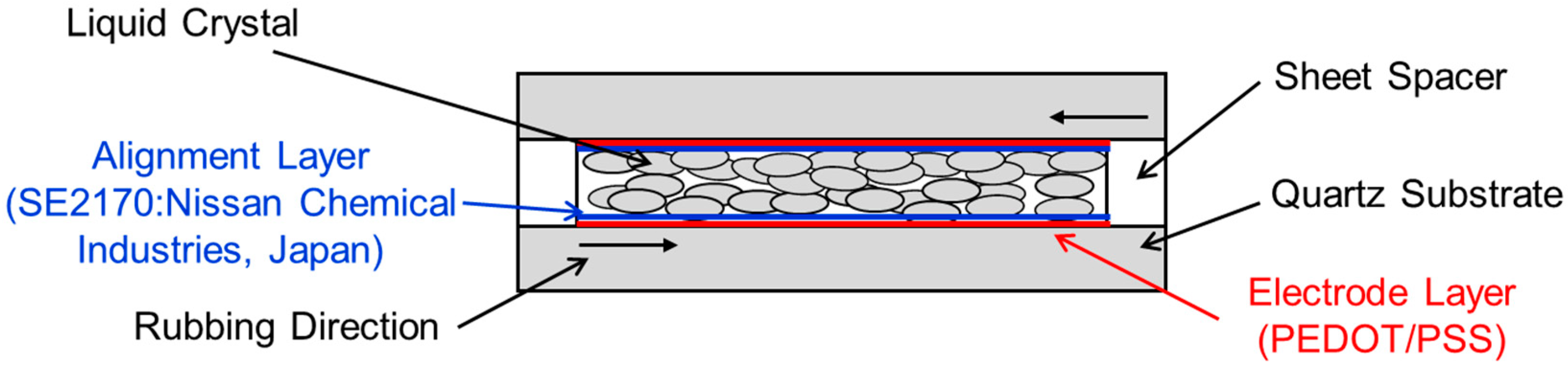
- Duong, T.Q.; Kobayashi, H.; Inoue, Y.; Moritake, H. Improved response time of thick liquid crystal device by using electrospun nanofiber. Jpn. J. Appl. Phys. 2017, 56, 061701. [Google Scholar] [CrossRef]
- Wang, L.; Lin, X.; Liang, X.; Wu, J.; Hu, W.; Zheng, Z.; Jin, B.; Qin, Y.; Lu, Y. Large birefringence liquid crystal material in terahertz range. Opt. Mater. Express 2012, 2, 1314–1319. [Google Scholar] [CrossRef]
- Ito, R.; Takahashi, T.; Honma, M.; Nose, T. Introduction of Liquid Crystal Device into THz Phase Imaging. In Terahertz, RF, Millimeter, and Submillimeter-Wave Technology and Applications VIII; Sadwick, L.P., Yang, T., Eds.; International Society for Optics and Photonics: San Francisco, CA, USA, 2015; p. 93620K. [Google Scholar]
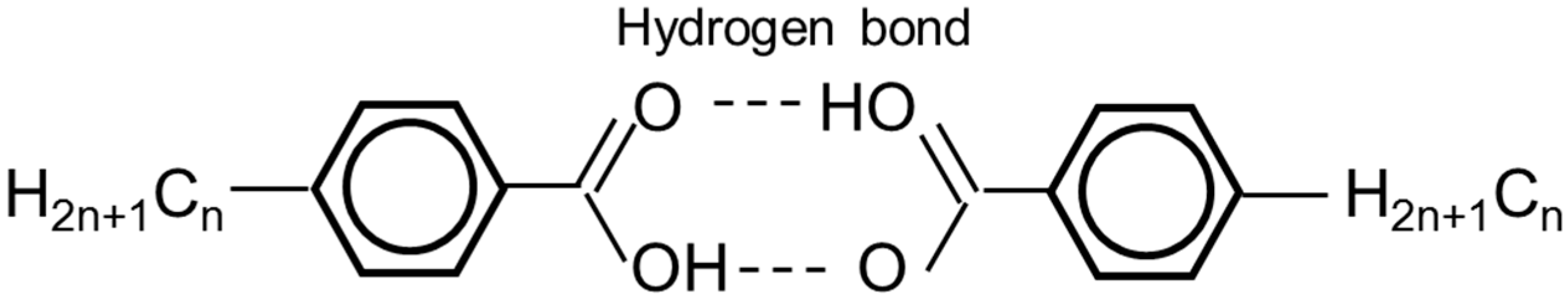
- Kato, T.; Frechet, J.M.J. A new approach to mesophase stabilization through hydrogen bonding molecular interactions in binary mixtures. J. Am. Chem. Soc. 1989, 111, 8533–8534. [Google Scholar] [CrossRef]
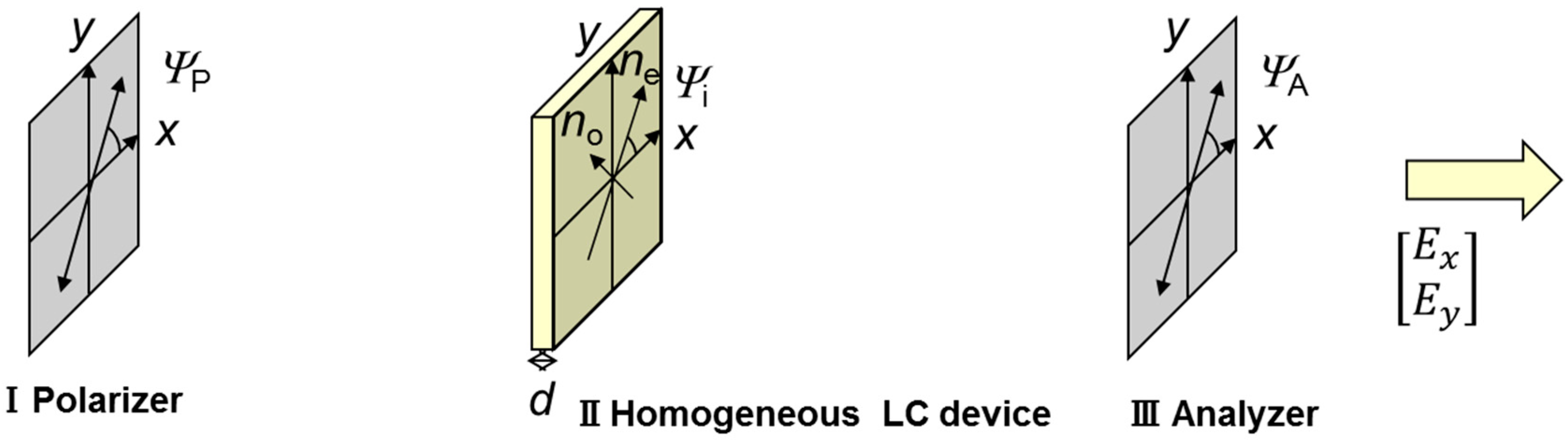
- Jones, R.C. A New Calculus for the Treatment of Optical SystemsI. Description and Discussion of the Calculus. J. Opt. Soc. Am. 1941, 31, 488–493. [Google Scholar] [CrossRef]
- Grischkowsky, D.; Keiding, S.; van Exter, M.; Fattinger, C. Far-infrared time-domain spectroscopy with terahertz beams of dielectrics and semiconductors. J. Opt. Soc. Am. B 1990, 7, 2006–2015. [Google Scholar] [CrossRef]


| Liquid Crystal | f (THz) | Δn | αe (cm−1) | αo (cm−1) | Δε6 | ||
|---|---|---|---|---|---|---|---|
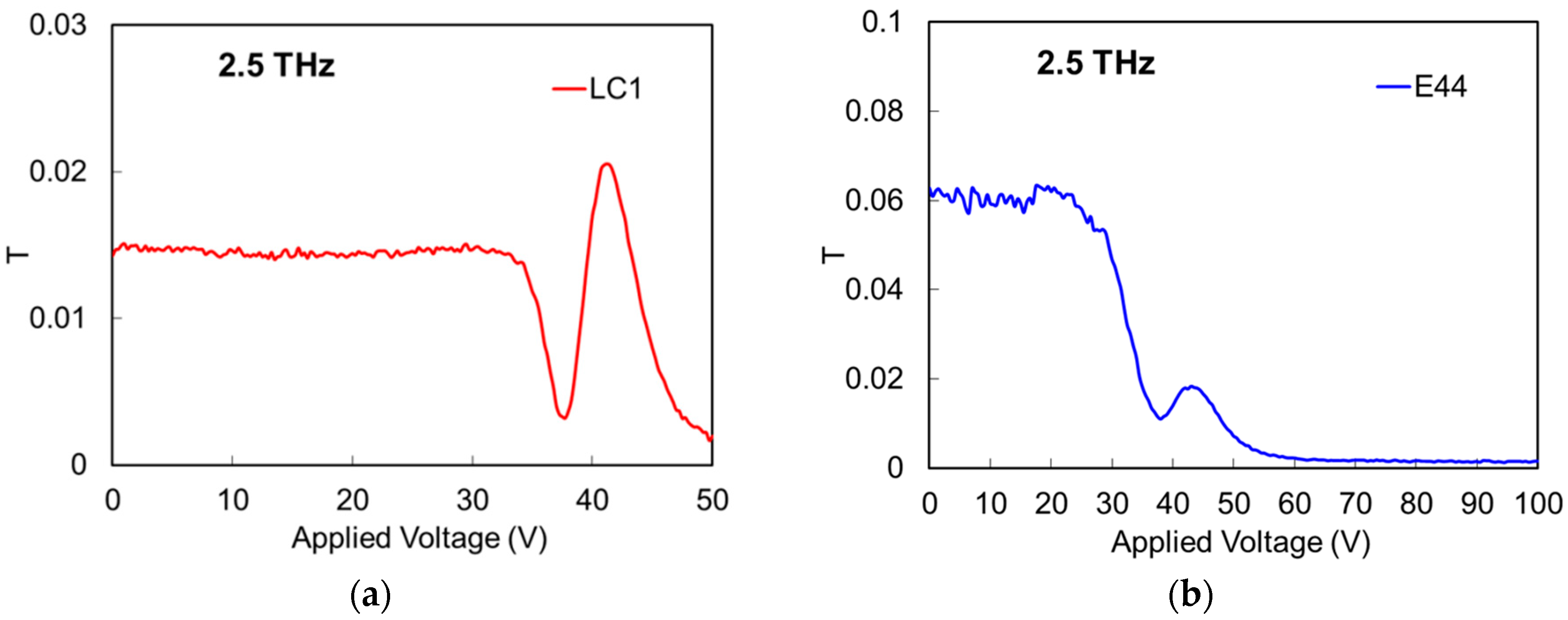
| LC1 | 2.5 | 0.17 | 0.035 | 37 | 0.035 | 37 | 0.6 (1 kHz) |
| E44 1 | 2.5 | 0.2 | 0.022 | 23.5 | 0.06 | 64.1 | 16.8 (1 kHz) |
| K15 2 | 2.5 | 0.165 | 0.0159 | 16.9 | 0.0379 | 40.4 | 20.07 (1 kHz) |
| E7 3 | 1 | 0.14 | 0.015 | 3 | 0.035 | 7 | 13.8 (1 kHz) |
| NJU-LDn-4 4 | 1.6 | 0.314 | 0.0526 | 12 | 0.0352 | 18 | 6.01 (1 kHz) |
| 1825 5 | 2.5 | 0.371 | 0.0363 | 19 | 0.0262 | 13.7 | 17.0 (1.5 kHz) |
© 2018 by the authors. Licensee MDPI, Basel, Switzerland. This article is an open access article distributed under the terms and conditions of the Creative Commons Attribution (CC BY) license (http://creativecommons.org/licenses/by/4.0/).
Share and Cite
Ito, R.; Honma, M.; Nose, T. Electrically Tunable Hydrogen-Bonded Liquid Crystal Phase Control Device. Appl. Sci. 2018, 8, 2478. https://doi.org/10.3390/app8122478
Ito R, Honma M, Nose T. Electrically Tunable Hydrogen-Bonded Liquid Crystal Phase Control Device. Applied Sciences. 2018; 8(12):2478. https://doi.org/10.3390/app8122478
Chicago/Turabian StyleIto, Ryota, Michinori Honma, and Toshiaki Nose. 2018. "Electrically Tunable Hydrogen-Bonded Liquid Crystal Phase Control Device" Applied Sciences 8, no. 12: 2478. https://doi.org/10.3390/app8122478