Article

Enhancing Heat Transfer Efficiency in Permanent Magnet Machines through Innovative Thermal Design of Stator Windings

1
Department of Mechanical and Construction Engineering, Northumbria University, Newcastle upon Tyne NE1 8ST, UK
2
School of Engineering, Newcastle University, Newcastle upon Tyne NE1 7RU, UK
*
Author to whom correspondence should be addressed.
Appl. Sci. 2024, 14(6), 2658; https://doi.org/10.3390/app14062658
Submission received: 29 February 2024 / Revised: 15 March 2024 / Accepted: 16 March 2024 / Published: 21 March 2024

Abstract

:

Featured Application

The work specifically targets the enhancement of cooling mechanisms in high-power permanent magnet electrical machines, with a direct application in improving the thermal management of stator windings in such devices. This advancement can significantly benefit sectors like aerospace, where the efficiency, reliability, and longevity of electrical machines are critical.

Abstract

This paper investigates innovative methods for enhancing heat transfer efficiency in high-power permanent magnet electrical machines. The objectives are to quantify the effects of increasing the air speed, increasing the turbulence intensity, and introducing the spacing between windings on cooling performance. The cooling of stator windings is studied through experimental wind tunnel testing and Computational Fluid Dynamics (CFD) modelling. The CFD model is validated against wind tunnel measurements to within 4 Kelvin (K). The results demonstrate that each enhancement method significantly improves the cooling capability. Increasing the air speed from 10 m/s to 40 m/s reduces the winding hotspot temperature by 34%. Introducing a high turbulence intensity of 40% leads to a 21% lower hotspot temperature compared to 0.5% turbulence intensity. Creating a 1.5 mm spacing between coils also substantially improves convection and conduction heat transfer. Overall, combining these optimised design parameters yields over a 40% reduction in hotspot temperature compared to the original design. This research provides practical guidance for maximising heat transfer efficiency in high-power permanent magnet machines, without increasing complexity. The findings will lead to higher machine efficiency, reliability, and longevity for aerospace and other applications.

1. Introduction

Over the past fifty years, civil aviation has experienced a remarkable growth rate of 9% per annum, which has inevitably led to an increase in the production of greenhouse gases, and is currently responsible for approximately 2.5% of global CO2 emissions [1]. The current gas turbine technology possesses limited potential for further emission reductions, and yet the industry has committed to ambitious targets, including reductions of up to 70% in carbon dioxide, 80% in oxynitride, and 70 dB in noise [2]. These stringent emission targets have spurred extensive research into the development of Hybrid Electric Aircraft (HEA).
Electric propulsion systems for HEA necessitate electrical machines with exceptional power density and efficiency [3]. Moreover, these machines must endure extreme operating conditions, such as high air speeds, low ambient temperatures, and low atmospheric pressure. Effective thermal management is crucial for the successful implementation of a high-power-density motor design. Historically, thermal design has often been considered secondary to electromagnetic performance within this field [4]. However, the generation of high power at high efficiency with minimal size and mass is heavily reliant upon high electric loading, rendering thermal design a critical factor. Furthermore, a reduction in the operating temperature can significantly extend the machine’s lifetime, as an increase of 10 °C can halve the insulation life [5]. Consequently, it is essential to employ effective thermal management strategies to minimise internal temperatures and thermal cycling.
Thermal management is a persistent challenge in high-power-density electrical machines, with inefficient heat dissipation potentially limiting their performance and lifespan [6,7]. Stator windings, integral to machine function, are particularly receptive to thermal stress [8]. Permanent magnet (PM) motors, known for their efficiency, face additional thermal concerns due to the sensitivity of the magnets to high temperatures [9]. Diverse thermal management strategies have been explored, including conventional air cooling, liquid cooling, and emerging techniques with phase-change materials [10]. While air cooling offers simplicity, optimising airflow and heat transfer within complex winding geometries remains an active research area [11].
Direct air cooling is a compelling alternative to liquid cooling systems, which often introduce complexity and potential failure points. One key parameter for optimising air-cooling efficiency is freestream turbulence intensity. Studies in turbine blade film cooling have demonstrated that increasing the turbulence intensity can significantly improve cooling effectiveness [12,13,14]. The mechanisms of film cooling, where injected air forms a protective layer, share similarities with convective cooling over complex surfaces such as stator windings. This suggests that turbulence intensity may offer similar benefits within electrical machines. This concept has been subsequently applied to the cooling performance of natural wind on solar PV panels, resulting in a substantial 40% enhancement by merely increasing the freestream turbulence intensity [15,16]. These successes make it worthwhile to investigate the potential benefits of freestream turbulence intensity on the cooling of newly designed winding configurations.
Computational Fluid Dynamics (CFD) plays a vital role in understanding thermal behaviour and designing effective cooling solutions [17,18]. Modelling advancements now enable detailed simulation of stator windings and their complex geometries, improving accuracy and design iteration speed. Despite progress, challenges remain in accurately capturing conjugate heat transfer, interfacial effects, and the influence of intricate winding features on airflow patterns. In prior research on Computational Fluid Dynamics (CFD) concerning the thermal efficiency of electrical motors, significant challenges have been identified. These encompass the implementation of conjugate heat transfer principles, especially in relation to the utilisation of slot liners and the refinement of mesh structures; the detailed representation and computational analysis of stator windings, with a particular emphasis on the terminal windings; and the precision of numerical outcomes derived from CFD simulations, as discussed in [19].
This study addresses these ongoing challenges by focusing on stator winding thermal management in permanent magnet motors. Concentrating on the thermal management of stator windings within aerospace electrical systems, our investigation evaluates three critical elements influencing the thermal regulation of these windings. The aim is to discover a practical strategy for improving the thermal management of stator windings, thereby enhancing their cooling efficiency without introducing complicated supplementary mechanisms.
The paper is structured into several core sections following this introduction. The Modelling Description section outlines the technical specifications and simulation assumptions of the permanent magnet machine. Within this, Approximation of Stator Windings and Description of CFD Simulations detail the modelling approaches for simulating stator winding thermal dynamics. Wind Tunnel Validation for CFD Simulations presents an empirical validation of the CFD model, ensuring its accuracy. Thermal Design Investigations with the Validated CFD Model examines the impacts of airflow velocity, turbulence intensity, and winding spacing on cooling efficiency, highlighting effective thermal management strategies. Section 5 summarises the study’s key findings, underscoring the enhanced heat transfer efficiency in high-power permanent magnet motors and offering practical industrial applications.

2. Modelling Description

The choice of a permanent magnet (PM) machine as the focal point of this study stems from its notable power-to-weight ratio and high efficiency. Design parameters of the PM machine are described in Table 1. Only copper loss is considered in the simulations, as electromagnetic calculations indicate that it dominates the thermal performance of the stator, accounting for the majority of the heat generation within the windings.
The analysed machine design assumes unrestricted airflow into the machine body (stator/winding/rotor). This is achieved by employing an open-frame arrangement, which differs from traditional closed-frame designs by allowing unrestricted airflow into the machine body. The endcaps used in this design are similar to those employed in the Siemens motor developed for aircraft propulsion [20]. In this initial study, the effect of endcaps on the mass and heat transfer are neglected. The simulations of the forced air cooling are based on an open-ended inlet, which is inspired and simplified from the industrial lightweight design of the end shield by Airbus, Rolls-Royce, and Siemens [20]. This reduces the weight of the machine and leaves more space for air channels to increase the air mass flow rate, leading to improved heat convection performance with direct air cooling. The simulated machine is presented in Figure 1a, and a unit of the machine’s active part is extracted to conduct the simulations, as shown in Figure 1b.

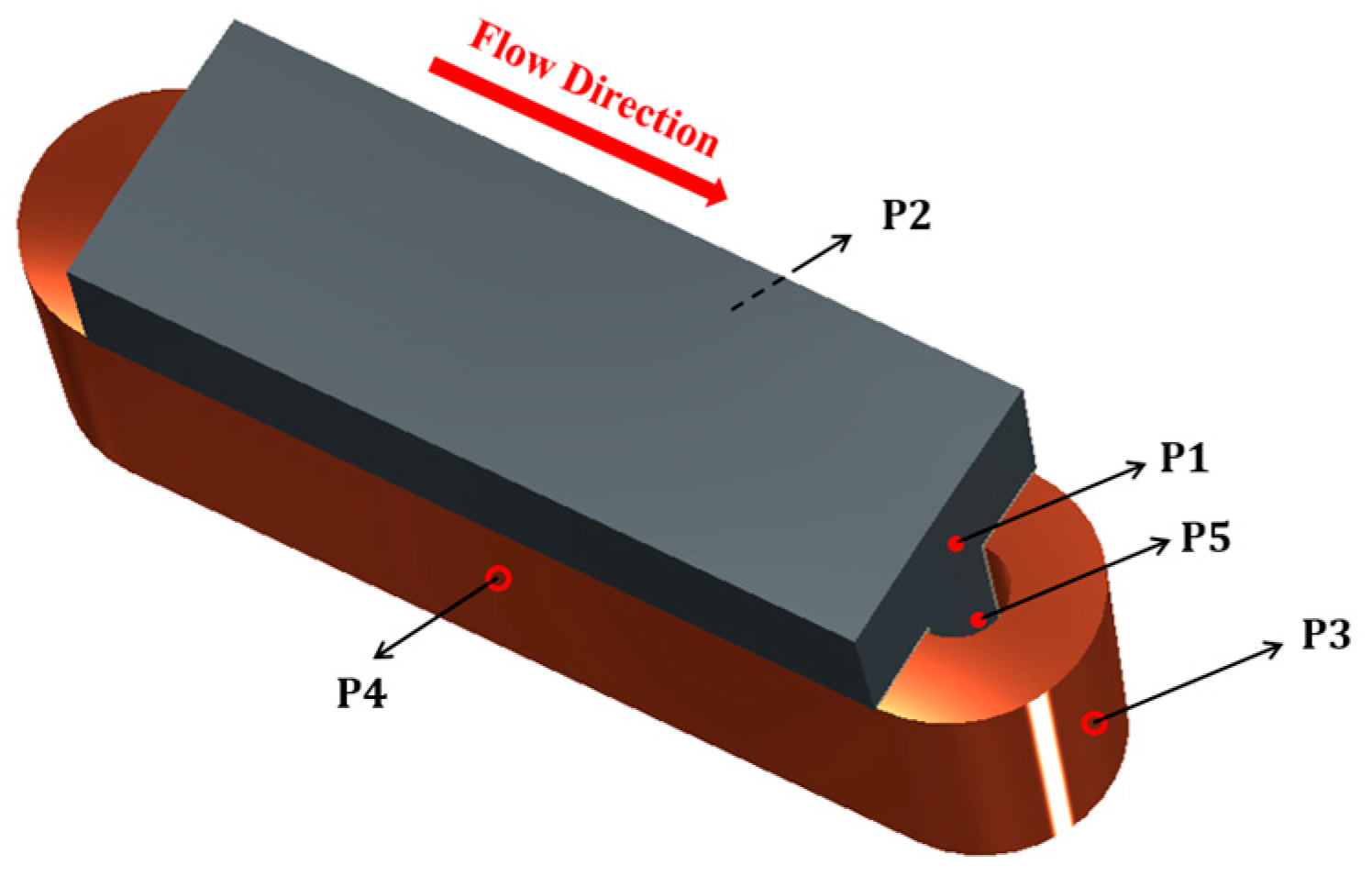
2.1. Approximation of Stator Windings

To streamline the thermal analysis and to diminish computational demands, the simulations employ an approximated representation of stator windings using an anisotropic lumped material model. This approach simulates the combined effects of the composite coils, restricting airflow solely to the windings’ exterior surfaces, thereby eliminating airflow between individual conductors. The lumped material model represents a composition comprising copper, enamel, and an impregnating agent (varnish, in this instance). It acknowledges that in a realistic scenario, the thermal resistance is affected by the presence of air pockets, a consequence of manufacturing variations. Additionally, the model incorporates a slot liner to reflect the application of Nomex paper in the model, measuring 0.25 mm in thickness.
In representing the copper loss within the windings, a loss density value of 106 W/m3 is used, correlating to an equivalent current density of about 12.0 ampere/mm2. The winding exhibits anisotropic thermal characteristics, defined along axes parallel and perpendicular to the conductors. The equivalent anisotropic thermal conductivity values ( k x , k y , k z ) are determined in Cartesian coordinates, aligning with the principal directions ( e x , e y , e z ) . The conductivity matrix is formulated as follows:
k i j = k x e x i e x j + k y e y i e y j + k z e z i e z j
This method, however, does not adequately account for the unique geometry of the end windings, whose curved structure introduces additional complexities in the simulation. To address these challenges, the model adopts a local cylindrical coordinate system, aligning the system’s axis with the central axis of the end winding on either side. Within this framework, the equivalent anisotropic thermal conductivity is recalibrated to reflect radial, tangential, and axial orientations, with the adaptations detailed in Figure 2.

2.2. Description of CFD Simulations

CFD simulations emerge as a vital complementary technique to traditional thermal experimental testing, offering significant advantages in terms of cost and time efficiency for thermal management strategies. The computational domain for these simulations is illustrated in Figure 3. To accurately follow the true geometric conditions of the model while conserving computational resources, periodic boundary conditions are applied to the side planes of the domain. The model uses both fluid and solid meshes created in Ansys ICEM CFD, specifically designed to address the conjugate heat transfer problem. This includes a refined proximity mesh around the unit to particularly model heat dissipation. The mesh’s total size is approximately one million cells, a figure determined after verifying that the simulation results are mesh-independent. The defined computational domain employs a velocity inlet and a pressure outlet, facilitating the process of air-cooling simulations and allowing for a comprehensive analysis of thermal management within the system.
The CFD simulations are conducted in a commercial fluid simulation software ANSYS Fluent 2020, using an iterative solver with a convergence criterion of 1 × 10⁻⁶ for both energy and momentum equations. The simulations are considered converged when the residuals for all equations drop below the specified criterion and remain stable. The k-epsilon turbulence model with the scalable wall function is used to provide an accurate solution to the turbulence modelling. Moreover, a wall function is needed because the standard k-epsilon turbulence model often fails to predict flow separations. Here, the scalable wall function is selected due to the local y+ of the boundary layer. For grids designed with a y+ < 11.225, this wall function virtually displaces the local y+ of the boundary layer to approximately 11.225, and for those with a y+ > 11.225, the scalable wall function provides identical results to the standard wall function. The y+ of the current case ranges from 10 to 15, hence the scalable wall function is an appropriate wall function to apply to the turbulence model. The unit of temperature is set to Kelvin, denoted as K.

3. Wind Tunnel Validation for CFD Simulations

Prior to advancing with additional numerical analyses, it is essential to validate the CFD simulation model against empirical data. In this study, wind tunnel experiments were performed on a constructed stator winding prototype to assess its thermal behaviour under specific airflow conditions. For this, the experimental setup was divided into three segments, including two lateral sections that offered structural integrity and enclosed the central testing segment, which mirrors the genuine stator winding arrangement, as shown in Figure 4. The lateral segments were fabricated using high-temperature resin, chosen for its thermal resistance of up to 238 °C, ensuring the model’s durability under high temperatures.
The central testing section employed materials that closely simulate those found in the actual machinery, including iron teeth and copper windings, to achieve a realistic representation. This section was composed of five iron teeth units and three copper winding units, supplemented by two 3D-printed winding blocks designed to minimise thermal leakage at the sides. The configuration of the middle section meticulously aligned with that of the original simulation design, incorporating slot liners but omitting impregnation to mirror the simulated conditions as accurately as possible.
It is noteworthy that the rotor was excluded from the CFD model as well as from the experimental framework, based on the premise that rotor-associated losses are not under consideration for this particular analysis. This decision ensures that the CFD simulation model directly corresponds with the experimental setup, focusing solely on the stator’s thermal performance for validation purposes.
Our experimental investigation was performed within an open-return wind tunnel. The dimensions of the tunnel’s test section were specified as 350 mm in height, 450 mm in width, and 3000 mm in length. Depending on the Reynolds number, the turbulence intensity (TI) within this section ranged from 0.4% to 0.6%, and the airflow velocity could be adjusted up to 35 m/s. The setup of this experimental arrangement is detailed in Figure 5, utilising the generated data to corroborate the numerical simulations and to refine the model as needed. Through this calibration process, the model is enhanced for more accurate CFD analyses concerning the motor assembly.
Five Type-K plug-in thermocouples were used in temperature monitoring within the experiment, strategically placed at five distinct locations to capture temperature variations accurately. These positions are illustrated in Figure 6, and ensured that all end-winding measurement sites were positioned on the downstream side to prevent any disturbance to airflow. Precision in the temperature measurements was optimised by situating all sensors at the central unit of each tooth and winding assembly. Additionally, ambient temperature readings were collected to establish temperature differentials across all five designated points. A prerequisite for data collection required the wind tunnel’s operation for a minimum duration of 60 min, ensuring the establishment of a steady-state condition prior to logging any measurements.
Upon conducting the experiments at an airflow speed of 10 m/s and a turbulence intensity of 0.5%, temperature increases across various locations were recorded, with findings detailed in Figure 7. In response to these empirical outcomes, simulation parameters were fine-tuned to align with the experimental conditions, facilitating a direct comparison between the simulated and actual temperature rises, as illustrated in the same Figure.
The strategy of employing an equivalent anisotropic lumped material to simulate the composite coils within the CFD framework demonstrated remarkable effectiveness. This approximation method successfully mirrored the thermal behaviour observed in the experiments, especially in predicting temperature rises on the surface of both middle and end windings. This comparison underscores the validity of the simulation approach, highlighting its potential as a reliable predictor of thermal dynamics in practical applications. The close match between the simulated results and experimental data reinforces the accuracy of the CFD model, suggesting that the simplifications made for the simulation did not significantly compromise the integrity of its predictions regarding thermal performance.
The CFD results slightly overestimated the temperature of the stator at Position 1 and Position 5, but generally provide a good match. The small overestimation indicates that the heat transferred through conduction (winding → slot liner → stator) in the experiment is less than that in the CFD simulation, as Positions 1 and 5 are in the stator rather than the winding. The reduced conducted heat in the experiment is due to the unavoidable existence of air pockets inside and around the windings in the experimental coil. These air pockets introduce extra thermal resistance to the winding block, reducing the thermal conductivity between the winding and the slot liner/stator and hence leading to a lower temperature in the stator compared to the CFD simulations. Other reasons should also be considered, such as the errors introduced by simulating heat transfer between different materials, including lumped winding blocks, slot liners, and stator tooth units, and the accuracy of the measuring positions due to the small size of the tooth.
It is noted that the reduced thermal conductivity due to the existence of air pockets should result in overestimated temperature values in the winding in the experimental testing, whilst the CFD results match the experimental measurements quite well at Positions 2, 3, and 4. This is possibly due to the factors such as the roughness of the winding surface and effective contact surface area between the winding and the air. In real life, the winding surfaces are formed through many turns of the copper wire. The surfaces are hence not flat, but rather full of surface irregularities introduced by the individual conductors. These “local bumps” effectively increase the roughness of the winding surface, as well as the contact area with the airflow, leading to higher heat transfer coefficients and hence a lower temperature value in the winding in the experiment testing. This underestimation counteracts the overestimation due to the air pockets, resulting in matching results at the winding position.
The CFD simulation model receives robust validation from the wind tunnel experiments across all five monitored positions, once stable temperature increments are realised experimentally. The differences observed between the empirical findings and the numerical predictions remain within a narrow margin of 4 K for each of the monitored locations. Additionally, the data illustrated in Figure 6 suggest that steady-state conditions within this experimental setup are attained roughly after a 20 min period. This revelation is crucial for understanding the dynamics of thermal performance and the effectiveness of the simulation model in capturing these dynamics over time. The consistency in achieving steady-state conditions in a relatively short time frame enhances the confidence in the experimental setup and the simulation model, providing a solid foundation for further analysis and validation efforts.

4. Thermal Design Investigations with the Validated CFD Model

In this section, we discuss the subsequent numerical simulations that were conducted considering three distinct air velocities and two levels of turbulence intensity. The influence of varying the air channel within the windings on cooling effectiveness is examined. For this, a representative model of the rotor geometry, intended to simulate the air gap between the rotor and stator, was implemented into the simulations. Additionally, an Iso-Surface spanning the X–Z plane was generated to observe temperature fluctuations within the aggregated windings, as illustrated in Figure 8.

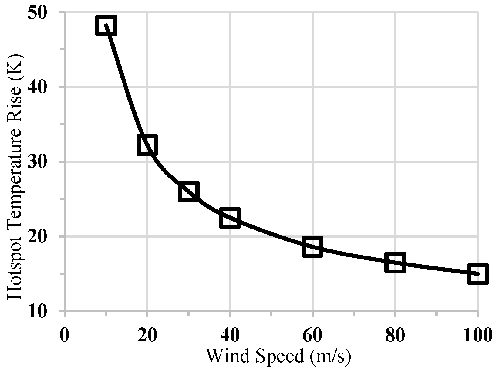
4.1. Effects of Airflow Velocity

Air velocity plays a crucial role in the efficiency of air-cooling systems. In the conducted simulations, air speeds from 10 to 100 m/s were tested. The conditions for the ambient temperature and turbulence intensity were standardised at 288 K (15 °C) and 0.5%, respectively. The temperature variation of maximum temperature increments across the range of air speeds is presented in Figure 9. Generally, the increment in hotspot temperature relative to the ambient temperature decreased as the air speed increased. However, the rate of the temperature change relative to the air speed diminished at higher air velocities.
It is noted that in all instances the temperature at the upstream end of the winding is marginally cooler than at the downstream end, attributed to the influence of airflow. This temperature differential becomes less pronounced with higher air speeds, owing to the diminished temperature increase.

4.2. Effects of Turbulence Intensity

Turbulent flow, characterised by chaotic changes in the pressure and flow velocity, significantly enhances the mixing of fluid particles, thereby improving heat transfer rates from the motor components to the cooling medium. Forced convection, a mechanism through which fluid motion is generated by an external source (such as fans or pumps), further augments this effect by actively removing heat from the surface of the stator windings. This concerted action of turbulent flow and forced convection ensures the efficient dissipation of heat, crucial for maintaining the operational integrity and extending the lifespan of permanent magnet motors. Recognising the complexity and importance of these thermal dynamics, we highlight their application in the thermal design of stator windings, presenting a more detailed understanding of the strategies that can be employed to enhance cooling performance in electrical machines.
Prior studies [21,22] have shown that an increase in turbulence intensity enhances the heat transfer coefficient, thereby improving cooling effectiveness on surfaces such as plates or cylinders. Building on this foundation, in our study, an investigation into the effect of freestream turbulence intensity on heat transfer across stator windings surfaces was conducted. Figure 10 illustrates the surface temperature distributions on the stator windings under conditions of low turbulence (0.5%), moderate turbulence (10%), and high turbulence (40%), at a wind speed of 10 m/s.
The findings highlight the significant role of freestream turbulence intensity on localised heat transfer. With a constant air speed of 10 m/s, the maximum surface temperature on the upwind-side end winding with a turbulence intensity of 0.5% is found to be 12 K higher than at a turbulence intensity of 40%, and 9 K higher on the downwind-side end winding. In the low-turbulence scenario, it is noted that laminar flow separation occurs prominently above the stator tooth, creating a large separation area above the stator core back. This separation hinders the airflow from efficiently dissipating heat away from the stator, thus lowering the heat transfer coefficient on the surface and resulting in suboptimal cooling performance. As the turbulence intensity increases to 10%, the previously open flow separation zones on the core back and beneath the rotor transform into closed separation areas, known as laminar separation bubbles in fluid dynamics, markedly affecting the thermodynamic and aerodynamic efficiency [23]. With a turbulence intensity of 40%, the adverse-pressure-gradient induced flow separation is minimised due to a more energetic flow, resulting in extensive areas of attached flow on both the upper and lower surfaces. The reduction in the separation bubble’s size and its shift towards the very leading edge of the stator and rotor enhance the surface heat transfer coefficients, thus significantly improving the cooling efficiency.
Increasing the turbulence intensity to apply this effect is comparatively straightforward. Globally, inflow turbulence can be induced upstream of the heat source by employing turbulence grids, while controlling the overall turbulence intensity through varying the grid sizes. Additionally, local effects can be adjusted by altering the local turbulence intensity, potentially through the implementation of micro vortex-generators [24] or by modifying the local surface curvature [25].

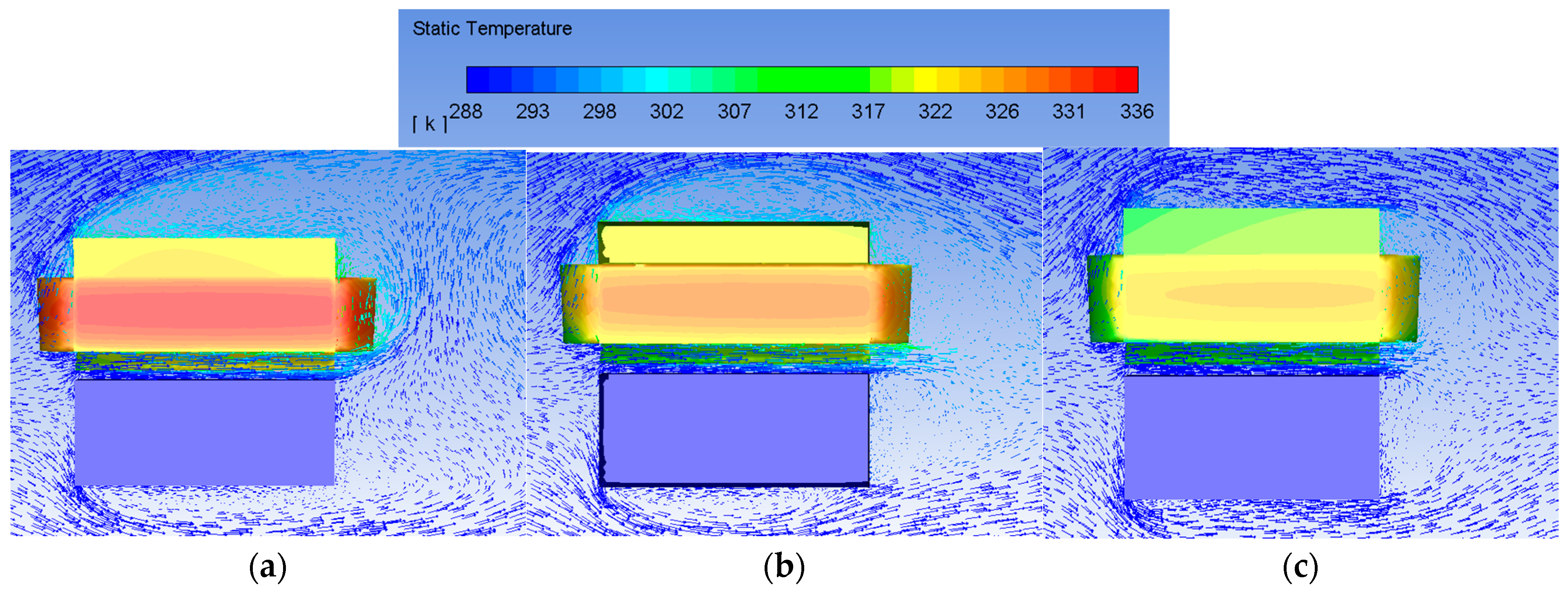
4.3. Effects of Spacing between Windings

The strategy to enhance heat transfer involves adjusting the spacing between individual winding coils while preserving the same magneto-motive force (MMF). This adjustment can be realised by increasing the coil fill factor (CFF), reducing the slot fill factor (SFF), or implementing both modifications. Initially, the windings exhibit an average circumferential width of 5.0 mm, with a coil fill factor (CFF) of 0.548 and a slot fill factor (SFF) of 0.434, denoting a standard winding configuration.
This analysis focuses on two distinct approaches to augment the spacing between windings:
  • Concept 1: Keeping the SFF constant while augmenting the CFF. This adjustment maintains the copper cross-sectional area as the inter-coil channel expands, enhancing the thermal conductivity of the coil without altering the coil’s loss for a given MMF.
  • Concept 2: Preserving the CFF constant and diminishing the SFF, achievable through reducing the wire diameter. This maintains the thermal conductivity of the winding constant while increasing the loss density in the copper for a constant MMF.
For this, a 0.25 mm thick Nomex-410 slot liner, with a thermal conductivity of 0.139 W/m/K, was utilised. In certain machines, the slot liner encases each coil entirely and is therefore positioned near the slot’s centre. Here, the significance of the slot liner’s presence between the windings was assessed regarding its effect on heat transfer, especially when cooling is facilitated via airflow down the slot’s centre. At an air speed of 10 m/s and a turbulence intensity of 0.5%, eliminating the slot liners between the windings resulted in a temperature decrease of 12 K inside the winding and 10 K at the tooth tip, equating to improvements of 25% and 20.8%, respectively. This enhancement is attributed to the Nomex paper’s extremely low thermal conductivity, which limits conductive heat transfer from the copper losses and obstructs convective heat transfer between the winding and the cooling medium. Consequently, the Nomex layers between the windings are omitted in further analyses, establishing a 0.5 mm air channel (comprising two 0.25 mm layers) as the baseline for subsequent investigations.
Figure 11 illustrates how varying the width of the inter-coil air channel influences the cooling efficiency at an air speed of 10 m/s and a turbulence intensity of 0.5%. A comparison of the results achieved with a 0 mm channel and those achieved with a 0.5 mm channel—representing windings with and without slot liners, respectively—shows identical temperature rises at these channel sizes, marking the “true” initial condition from a 0.5 mm channel width.
In the scenario where the SFF is constant and the CFF is increased, as the channel width enlarges, there is a corresponding change in the equivalent anisotropic thermal conductivities due to the altered slot composition. Consequently, as the air channel widens, the thermal conductivity and coil surface cooling improve, leading to a temperature decrease. Interestingly, beyond a 1.5 mm width, no substantial further reduction in temperature is observed, indicating a limit to the benefits of increased compression. The most significant temperature rise reduction of the hotspot, 28.7 K, is 19.3 K lower than in the original uncompressed windings with slot liners, and 8.9 K lower than in the uncompressed windings without slot liners, showcasing improvements of 40% and 24%, respectively. These improvements are attributed to an enhanced conductive heat transfer from the increased thermal conductivity of the combined winding blocks and improved convective heat transfer from the greater air channel widths.
Alternatively, maintaining a constant CFF results in the coil retaining anisotropic thermal conductivities equivalent to those of the original winding, since the copper percentage remains unchanged. Here, convective heat transfer emerges as the primary differential in cooling performance. However, maintaining the same coil MMF necessitates an increase in the current density as the copper volume diminishes, leading to a rapid increase in energy loss density as the channel widens, which counteracts the benefits of the improved convective heat transfer. The optimal channel width identified in this case is 1.5 mm, yielding a 33.7 K temperature rise of the hotspot, marking a 30% and 10.4% improvement over the original design with and without slot liners, respectively. When the channel width extends beyond 1.5 mm, the temperature rises significantly due to the escalating loss density.
Clearly, the first approach, maintaining the SFF while increasing the CFF, results in lower temperature rises for all channel widths. It is important to note, though, that practically increasing the CFF while maintaining the SFF (Concept 1) poses technical challenges, whereas decreasing the SFF while keeping the CFF constant (Concept 2) is more straightforward. Notably, effective cooling does not necessitate wide channels between coils. A 1.5 mm channel width, accounting for approximately 14% of the slot width, suffices for maximal effect in both scenarios. For research purposes, the first concept, which shows superior performance, is chosen for further investigation.
Figure 12 presents the variation in area-weighted average surface heat transfer coefficients with increasing channel widths. The removal of the slot liners between the windings resulted in a mean surface heat transfer coefficient of 52 W/m2/K, which rose to approximately 77 W/m2/K when the air channel width between the windings increased to 1.5 mm. No significant change can be observed when the channel width is beyond 1.5 mm, consistent with the variation in the hotspot temperature rise. Further expanding the air channel beyond this point is not recommended, as there is no significant thermal improvement.
The distribution of the surface heat transfer coefficients is presented in Figure 13, with the typical winding–winding channel widths ranging from 0.5 mm to 1.5 mm. It can be observed that, in terms of the 0.5 mm channel width, the winding surface towards the downwind-side end windings presents much worse heat transfer coefficients than that near the upwind-side end windings. The highest heat transfer coefficient at the upwind side is more than 100 W/m2/K, while the lowest near the downwind side is less than 10 W/m2/K. This is because the air slows down as it flows axially down the narrow 0.5 mm channel. The improvement is significant when increasing the winding–winding channel width to 1.0 mm and 1.5 mm. Generally, the lower part of the winding has a better heat transfer coefficient than the higher part, due to the airflow adjacent to the stator tooth tip.
The turbulence intensity has a significant impact on cooling performance, as presented in Section 4.2. At the wind speed of 10 m/s and with the 1.5 mm optimal winding–winding channel width, the variation in surface heat transfer coefficients at a turbulence intensity of 40% is compared with that at a turbulence intensity of 0.5%. The significant improvements due to the higher turbulence intensity appear near the upwind-side end winding. It can be observed that the heat transfer coefficients near the upwind-side end winding at the 40% turbulence intensity are almost doubled compared to those at the turbulence intensity of 0.5%, leading to an area-weighted average surface heat transfer coefficient of 85 W/m2/K, which is 10% higher than that of the case at 0.5% turbulence intensity.

4.4. Overall Improvement Analysis

Following the insights detailed in the preceding sections, adjustments were implemented in the initial design to enhance its performance. By increasing the coil fill factor while keeping the slot fill factor constant and introducing a 1.5 mm separation between the coils, along with a turbulence intensity of 40%, the revised model is evaluated against the standard design. It is crucial to note that any performance enhancements must be assessed at a consistent airflow velocity to accurately highlight the design’s benefits. In the enhanced design, the peak temperature is reduced by 21 K compared to the original model, resulting in a 44% improvement. This enhancement is attributed to the increased efficiency in both the convective and conductive heat transfer. Importantly, these advancements are achieved without the need for complex modifications and are maintained at a consistent MMF.
In the context of industrial design, understanding the intricacies of heat transfer mechanisms, specifically conduction and convection, is of paramount importance. To facilitate this comprehension, a thermal equivalent circuit has been distilled from the optimised design, which is explained in Figure 14. In this representation, the variables P (W), R (K/W), and T (K) signify the user-defined heat power, equivalent thermal resistance, and local temperature, respectively. Furthermore, the subscripts W, S, and A correspond to the winding, stator, and ambient conditions, respectively. It should be noted that RS encompasses the thermal resistance attributable to conduction within the stator, inclusive of slot liners. The thermal resistances RSA and RWA are indicative of the convective heat transfer from the stator laminations to the ambient environment and from the winding to the ambient environment, respectively. These resistances are modifiable through the manipulation of convective parameters such as air velocity and turbulence intensity. Quantification of these thermal resistances can be achieved through the employment of mean heat transfer coefficients.
In the simplified thermal equivalent circuit, the transfer of the input heat power is divided into two routes: one is the convection route, which is through the winding surface to the ambient, and the other is the conduction route, which is through the winding to the stator and subsequently to the ambient. The total surface heat flux through the convection route is presented in Figure 15. The upwind side of the winding presents a total surface heat flux higher than 3000 W/m2, while the downwind side only shows that the heat flux can be lower than 1000 W/m2 in the area where the velocity of the air is extremely low.
The transferred heat power through the conduction and convection routes can be determined by integrating the corresponding total surface heat flux. For this specific case, 63% of the transferred heat power is mitigated through the convection route and 37% is mitigated through the conduction route.

5. Conclusions

This study provides critical insights into pioneering strategies to boost the heat transfer efficiency in the stator windings of high-power permanent magnet motors. Through wind tunnel experimental tests and the calibration of a Computational Fluid Dynamics (CFD) model, this research examined how increased air velocity, enhanced turbulence intensity, and the implementation of air channels between the windings impact cooling efficacy. The results indicated that each of these variables can individually enhance the heat transfer efficiency by over 25%. This study investigated the importance of maintaining spacing between coils, presenting two viable solutions that can serve as practical design guidelines for industrial usage. It was shown that, at a consistent air velocity, the synergistic effect of a heightened turbulence intensity and an optimal spacing between the windings can lead to a 44% reduction in the peak temperature. Additionally, this research introduced a thermal equivalent circuit model to demonstrate the heat transfer dynamics in the optimised design, revealing that 63% of the heat loss is mitigated through convection between the windings and the air.
This investigation not only deepens the understanding of thermal management within electrical machines, but also provides actionable recommendations for enhancing the cooling efficiency of high-power permanent magnet motors. Such advancements promise to improve the efficiency, reliability, and service life of these systems in practical applications, marking a significant contribution to the field.

Author Contributions

Conceptualization, X.S. and B.M.; methodology, X.S., X.D., B.M. and R.W. (Rafal Wrobel); software, X.S.; validation, X.D., B.M., R.W. (Rafal Wrobel) and R.W. (Richard Whalley); formal analysis, X.S.; investigation, X.S., X.D. and B.M.; resources, B.M. and R.W. (Richard Whalley); data curation, X.S.; writing—original draft preparation, X.S.; writing—review and editing, X.D.; visualization, X.S.; supervision, B.M.; project administration, X.S.; funding acquisition, B.M. All authors have read and agreed to the published version of the manuscript.

Funding

This research received no external funding.

Institutional Review Board Statement

Not applicable.

Informed Consent Statement

Not applicable.

Data Availability Statement

Data is contained within the article.

Conflicts of Interest

The authors declare no conflicts of interest.

References

  1. Larsson, J.; Elofsson, A.; Sterner, T.; Åkerman, J. International and national climate policies for aviation: A review. Clim. Policy 2019, 19, 787–799. [Google Scholar] [CrossRef]
  2. Greitzer, E.M.; Bonnefoy, P.; De la Rosa Blanco, E.; Dorbian, C.; Drela, M.; Hall, D.; Hansman, R.; Hileman, J.; Liebeck, R.; Lovegren, J. N+ 3 Aircraft Concept Designs and Trade Studies, Final Report; Nasa cr-2010-216794/vol2; NASA Glenn Research Center: Cleveland, OH, USA, 2010. [Google Scholar]
  3. Mecrow, B.C.; Bennett, J.W.; Jack, A.G.; Atkinson, D.J.; Freeman, A.J. Drive topologies for solar-powered aircraft. IEEE Trans. Ind. Electron. 2009, 57, 457–464. [Google Scholar] [CrossRef]
  4. Jordan, S.; Baker, N.J. Design and build of a mass critical, air-cooled transverse flux machine for aerospace. In Proceedings of the 2016 XXII International Conference on Electrical Machines (ICEM), Lausanne, Switzerland, 4–7 September 2016; pp. 1453–1458. [Google Scholar]
  5. Simpson, N.; Wrobel, R.; Mellor, P.H. Estimation of equivalent thermal parameters of impregnated electrical windings. IEEE Trans. Ind. Appl. 2013, 49, 2505–2515. [Google Scholar] [CrossRef]
  6. Yang, Y.; Bilgin, B.; Kasprzak, M.; Nalakath, S.; Sadek, H.; Preindl, M.; Cotton, J.; Schofield, N.; Emadi, A. Thermal management of electric machines. IET Electr. Syst. Transp. 2017, 7, 104–116. [Google Scholar] [CrossRef]
  7. Nishanth, F.; Johnson, M.; Severson, E.L. A review of thermal analysis and management of power dense electric machines. In Proceedings of the 2021 IEEE International Electric Machines & Drives Conference (IEMDC), Hartford, CT, USA, 17–20 May 2021; pp. 1–8. [Google Scholar]
  8. Boglietti, A.; Cavagnino, A.; Staton, D.; Shanel, M.; Mueller, M.; Mejuto, C. Evolution and modern approaches for thermal analysis of electrical machines. IEEE Trans. Ind. Electron. 2009, 56, 871–882. [Google Scholar] [CrossRef]
  9. Gerada, D.; Mebarki, A.; Mokhadkar, R.; Brown, N.; Gerada, C. Design issues of high-speed permanent magnet machines for high-temperature applications. In Proceedings of the 2009 IEEE International Electric Machines and Drives Conference, Miami, FL, USA, 3–6 May 2009; pp. 1036–1042. [Google Scholar]
  10. Wang, X.; Li, B.; Gerada, D.; Huang, K.; Stone, I.; Worrall, S.; Yan, Y. A critical review on thermal management technologies for motors in electric cars. Appl. Therm. Eng. 2022, 201, 117758. [Google Scholar] [CrossRef]
  11. Estenlund, S. Air Cooling of an Emsm Field Winding. Licentiate Thesis, Lund University, Lund, Sweden, 2018. [Google Scholar]
  12. Cheng, L.; Zhu, H.; Jiang, R.; Fu, Z.; Xu, W. The effect of turbulence intensity on full coverage film cooling for a turbine guide vane. In Proceedings of the 2018 Joint Propulsion Conference, Cincinnati, OH, USA, 9–11 July 2018; p. 4523. [Google Scholar]
  13. Wright, L.M.; McClain, S.T.; Clemenson, M.D. Effect of freestream turbulence intensity on film cooling jet structure and surface effectiveness using PIV and PSP. J. Turbomach. 2011, 133, 041023. [Google Scholar] [CrossRef]
  14. Bogard, D.G.; Thole, K.A. Gas turbine film cooling. J. Propuls. Power 2006, 22, 249–270. [Google Scholar] [CrossRef]
  15. Fouladi, F.; Henshaw, P.; Ting, D.S.-K.; Ray, S. Wind turbulence impact on solar energy harvesting. Heat Transf. Eng. 2020, 41, 407–417. [Google Scholar] [CrossRef]
  16. Iakovidis, F.; Ting, D.S.-K. Effect of Free Stream Turbulence on Air Cooling of a Surrogate PV Panel. Proceedings the of ASME 2014 International Mechanical Engineering Congress and Exposition, Montreal, QC, Canada, 14–20 November 2014; Volume 46521, p. V06BT07A001. [Google Scholar]
  17. Zhao, C.-J.; Han, J.-W.; Yang, X.-T.; Qian, J.-P.; Fan, B.-L. A review of computational fluid dynamics for forced-air cooling process. Appl. Energy 2016, 168, 314–331. [Google Scholar] [CrossRef]
  18. Banjac, M.J. Application of Computational Fluid Dynamics in cooling systems design for special purpose objects. FME Trans. 2014, 42, 26–33. [Google Scholar] [CrossRef]
  19. Shen, X.; Mecrow, B.; Deng, X.; Donaghy-Spargo, C.; Whalley, R.; Chakraborty, N. Direct Air Cooling of High-Power Permanent Magnet Machines. In Proceedings of the 2019 IEEE Energy Conversion Congress and Exposition (ECCE), Baltimore, MD, USA, 29 September–3 October 2019; pp. 5637–5644. [Google Scholar]
  20. Economou, J.T.; Tsourdos, A.; Wang, S. Design of a Distributed Hybrid Electric Propulsion System for a Light Aircraft based on genetic algorithm. In Proceedings of the AIAA Propulsion and Energy 2019 Forum, Indianapolis, IN, USA, 19–22 August 2019; p. 4305. [Google Scholar]
  21. Kondjoyan, A.; Daudin, J. Effects of free stream turbulence intensity on heat and mass transfers at the surface of a circular cylinder and an elliptical cylinder, axis ratio 4. Int. J. Heat Mass Transf. 1995, 38, 1735–1749. [Google Scholar] [CrossRef]
  22. Kondjoyan, A.; Péneau, F.; Boisson, H.-C. Effect of high free stream turbulence on heat transfer between plates and air flows: A review of existing experimental results. Int. J. Therm. Sci. 2002, 41, 1–16. [Google Scholar] [CrossRef]
  23. Shen, X.; Avital, E.; Zhao, Q.; Gao, J.; Li, X.; Paul, G.; Korakianitis, T. Surface curvature effects on the tonal noise performance of a low Reynolds number aerofoil. Appl. Acoust. 2017, 125, 34–40. [Google Scholar] [CrossRef]
  24. Heffron, A.P.; Williams, J.J.; Avital, E. Numerical and Experimental Study of Microvortex Generators. J. Aircr. 2018, 55, 2256–2266. [Google Scholar] [CrossRef]
  25. Shen, X.; Avital, E.; Paul, G.; Rezaienia, M.A.; Wen, P.; Korakianitis, T. Experimental study of surface curvature effects on aerodynamic performance of a low Reynolds number airfoil for use in small wind turbines. J. Renew. Sustain. Energy 2016, 8, 053303. [Google Scholar] [CrossRef]
Figure 1. (a) Demonstration of the active part of the PM machine. (b) An extracted unit used in the simulation, including the stator core back, end winding, slot liner, and rotor. Red solid lines in (a) highlight the unit extracted from the entirety of the active area for focused simulation analysis.
Applsci 14 02658 g001
Figure 2. Local cylindrical coordinates for the end windings and Cartesian coordinates for the mid windings.
Applsci 14 02658 g002
Figure 3. The CFD simulation domain with boundary conditions.
Applsci 14 02658 g003
Figure 4. Schematic illustration of the experimental setup and the assembled model for wind tunnel testing, which serves as a basis for the CFD simulation domain and boundary conditions.
Applsci 14 02658 g004
Figure 5. The testing setup and configuration of the wind tunnel experiment. The solid arrowhead represents the direction of airflow within the wind tunnel, while hollow arrowheads function as indicators, pointing to and labelling specific experimental instruments.
Applsci 14 02658 g005
Figure 6. Thermal monitoring positions demonstrated in an extracted unit. Position 2 (P2) is at the symmetrical position of Position 1 (P1). Hollow circles indicate the positions where the surface temperature is monitored, while solid circles denote the positions where the temperature is monitored 5 mm below the surface.
Applsci 14 02658 g006
Figure 7. Comparison of experimental and numerical results at five monitoring positions.
Applsci 14 02658 g007
Figure 8. An Iso-Surface created across the stator windings.
Applsci 14 02658 g008
Figure 9. Rise in temperature of winding hotspot at air speeds ranging from 10 m/s to 100m/s. The ambient air temperature is 288 K.
Applsci 14 02658 g009
Figure 10. Winding temperature distributions at airflow speed of 10 m/s with an inflow turbulence intensity of (a) 0.5%, (b) 10%, or (c) 40%. The flow direction is from left to right in all of the cases.
Applsci 14 02658 g010
Figure 11. Effects of increasing the air channel width between windings upon the hotspot, maintaining either a constant slot fill factor or a constant conductor fill factor.
Applsci 14 02658 g011
Figure 12. Area-weighted average surface heat transfer coefficients varying with increasing air channel widths.
Applsci 14 02658 g012
Figure 13. Contours of surface heat transfer coefficients with the channel widths of (a) 0.5 mm, (b) 1.0 mm, and (c) 1.5 mm at a wind speed of 10 m/s and 0.5% turbulence intensity. The flow direction is from left to right.
Applsci 14 02658 g013
Figure 14. An equivalent thermal circuit of the optimised design.
Applsci 14 02658 g014
Figure 15. Total surface heat flux distributions through the conduction route in the optimised design. The flow direction is from left to right.
Applsci 14 02658 g015
Table 1. Technical details of the selected PM machine.
Rated PowerNumber of Stator Teeth Slot Fill FactorStator LengthStator ODRotor IDStator Slot AreaWinding Length
250 kW7243.4%50 mm404.4 mm300 mm193 mm263.4 mm
Disclaimer/Publisher’s Note: The statements, opinions and data contained in all publications are solely those of the individual author(s) and contributor(s) and not of MDPI and/or the editor(s). MDPI and/or the editor(s) disclaim responsibility for any injury to people or property resulting from any ideas, methods, instructions or products referred to in the content.

