1. Introduction
Ionic liquids as high-tech technical fluids have been in practical use in various fields of technology for several years. Ionic liquids are applied in the field of Technology as additives, solvents, electrolytes, catalysts, reagents, lubricants and heat transfer and storage fluids, etc. In addition, they are also used in the areas of heating, ventilation and air conditioning (HVAC), as a sealing fluid, as a cutting fluid designed specifically for metalworking processes, e.g., for cutting and drilling, and as operating fluids in different technical systems, they are referred to by a unified term: ionic engineering fluid. Therefore, their applications cover many diverse technical fields, and even megatrends like mobility, health and the green economy.
Due to their excellent lubricating and other physicochemical properties, they have also made their way into the field of Hydraulic Drive Technology. In most of the mentioned cases of using ionic liquids, they only need to provide one, or maybe two or three good physicochemical properties. In the case of use as a hydraulic fluid, an ionic liquid must have several excellent properties at the same time, of ten or more. Therefore, the development of ionic liquids appropriate for hydraulic systems took more than a decade. The development included the identification of material properties important for their use as a hydraulic fluid, extensive pre-selection processes and the laboratory testing of suitable ionic liquids, as well as long-term testing using real hydraulic components under real operating conditions [
1]. Now, we can talk about a completely new type of hydraulic fluid, ionic hydraulic fluid—HIL.
Ionic hydraulic fluids are (for) now being considered alternative hydraulic fluids. This is similar to the use of water, or water-based fluid, as a hydraulic fluid, except that, in this case, it is necessary to compensate for or adapt to the shortcomings of the use of water by using special materials or coatings [
2,
3,
4]. Today, ionic hydraulic fluids are suitable for use mainly in hydraulic applications in areas where classic hydraulic fluids cannot solve the problem satisfactorily, or the challenge of the application, or cannot solve it at all. Compared to classic hydraulic fluids, ionic hydraulic fluids have excellent individual physicochemical properties, and, due to their properties, cover the field of both highly additive mineral hydraulic oils and non-flammable and more environmentally friendly classic hydraulic fluids simultaneously.
Before a new type of hydraulic fluid is used in a hydraulic system, it is absolutely necessary to check the impact of the new fluid on individual components and their materials. In particular. the compatibility of the fluid with all the materials incorporated in the component is definitely an extremely important aspect. This concerns the compatibility of metallic materials (e.g., valve housings, pumps, filters and cylinders, as well as hydraulic pipes and fittings), as well as non-metallic materials such as flexible pipes, the corrosion protection of component surfaces (including the painting of the tank, especially the interior), and, of course, all the seals. This is particularly important, as seals are a key element that ensures flawless operation of the system, where we use a whole range of different materials for different seals.
2. Function, Types, Shapes and Hydraulic-Seal Materials
The general function of a seal built in between two surfaces in a component is to seal an area of higher pressure against an area of lower pressure, of either liquid or gas. This generalised definition applies both to the sealing of two stationary surfaces or a combination of a stationary and a moving surface. Seal effectiveness is measured in terms of leakage. A leak-free seal through the contact surfaces must be ensured over the entire range of operating parameters, which is achieved both with the appropriate shape and material of the seal.
The form of seals has developed gradually from the earliest forms of seals, just some space between two surfaces filled with sealing material, to today’s more efficient forms of seals. The first advance in sealing technology was the development of V-shaped and U-shaped sealing rings (called U-Cups). These forms of seals are relatively effective, but they already require changes in the design of the sealing space. Additionally, a sealing effect is only in one direction of movement, and is only activated when a pressure is present. Thus, two seals are needed to seal in both directions. Apart from that, the operating pressure was also limited—in the case of U-Cups, to around 100 bar, and in the case of V-rings, to approx. 140 bar, which is a fairly low operating pressure for today’s hydraulic systems. it was necessary to install a package, e.g., three or more V-seals, which requires a larger installation space for the seals.
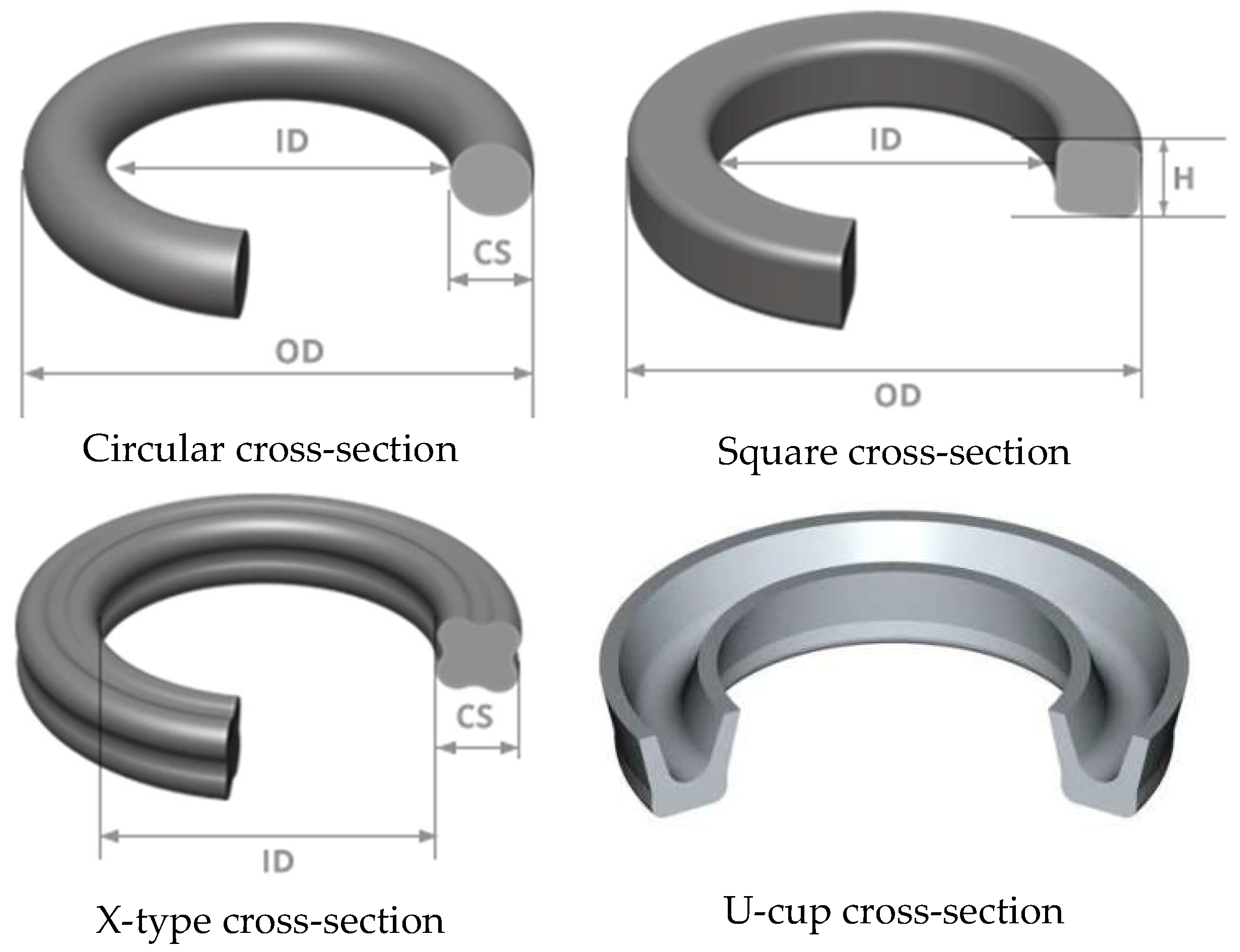
Further development in the field of seals led to ring-shaped seals, in the case of the most commonly used circular cross-section, called O-rings. Apart from the circular cross-section, as in the case of O-rings, ring-shaped seals also have other cross-sectional shapes: square rings, D-rings, X-rings, T-seals and cup seals—
Figure 1. Due to their simple shape, standardisation of dimensions, and their simplicity and effectiveness in sealing, ring-shaped seals are indispensable today too, used for sealing stationary surfaces or at the low-movement speed of one surface—s.c. static seals.
Although the O-ring has been the most popular design for static seals, square rings are more effective static seals because they provide a wider seal-contact area and thus a more effective seal effect; plus, they do not twist and roll when moving. However, due to the larger contact surface, greater friction occurs during movement, which is reduced by the other mentioned forms of ring seals.
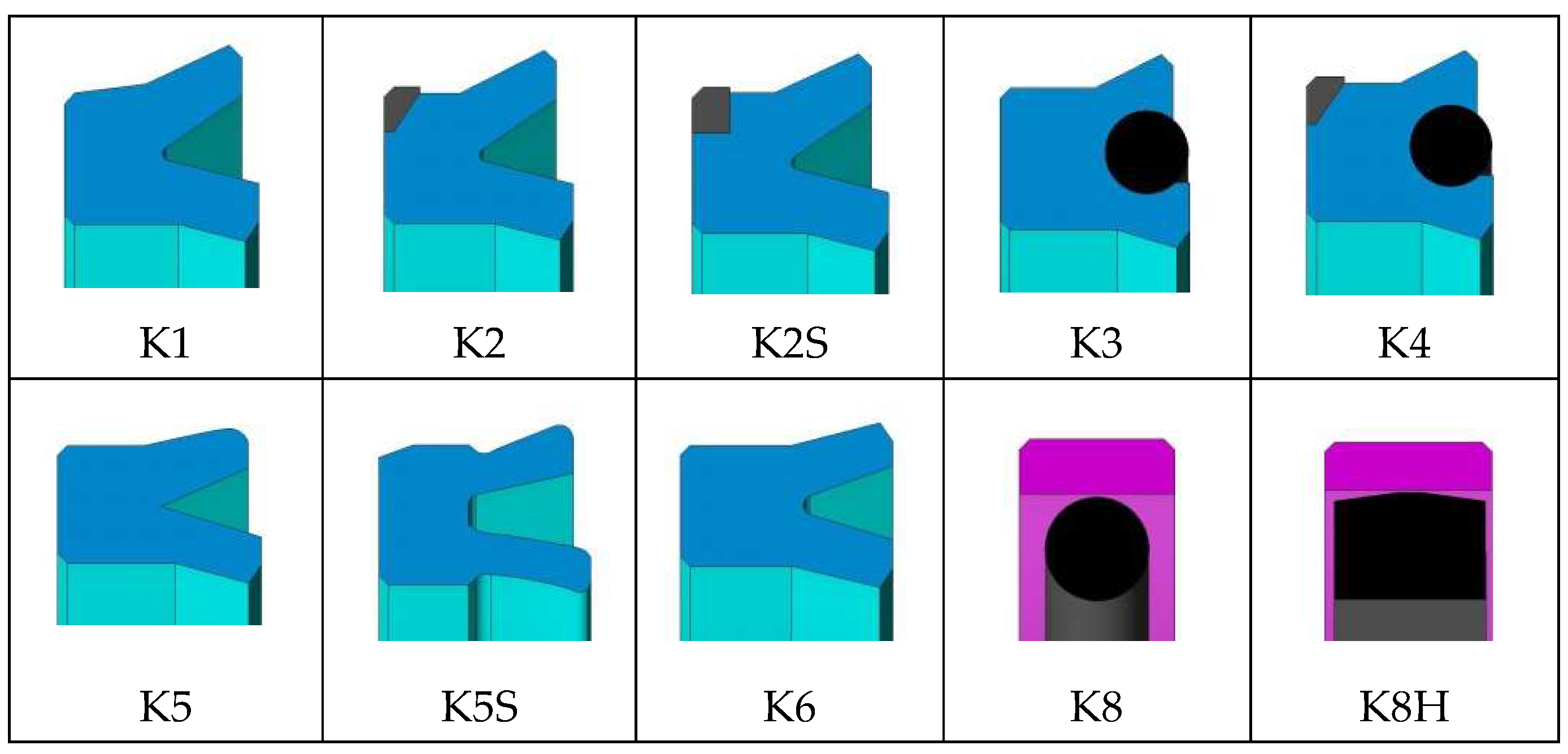
In the case where one surface moves relative to another, it is necessary to use a more suitable shape that ensures both good sealing and low friction. In this case, it is a question of dynamic seals, which, depending on the place of installation and, thus, the size, can be further divided into seals suitable for sealing pistons and piston-rod seals, as is the case with hydraulic cylinders. In the area of fluid power technology, different profiled seals are implemented in regard to application. These are mainly different forms of U-cup seals, in the version without or with a support ring, generally known as lip seals. Some examples of the usually very wide range and variety of different piston-seal designs as produced by specialist seal manufacturers are shown in
Figure 2.
In order to achieve an effective seal, not only is the shape of the seal important, but so is the material of the seal. Here, the compatibility of various seal materials with hydraulic fluids is at the forefront of this paper. The earliest seals were nothing more than stuffing boxes packed with waxed string or cord, leather strips, pieces of rubber, cotton, wool, or even paper. Later, rubber was used in the case of the O-ring.
In these early examples of materials, there was no emphasis on material compatibility, as the fluid used was first water, and, later, mineral-based hydraulic oil. With the use of different types of hydraulic fluids, oil additives and new seal materials, the issue of compatibility has become extremely important, especially in cases where it is not a matter of using a conventional, well-known type of hydraulic fluid, but a completely new fluid, such as ionic hydraulic fluids.
Several materials are used for today’s seals. These are polyurethane (HPU), elastomers such as nitrile (NBR), fluorocarbon and elastomers based on fluororubber (FPM/ FKM), also known as Viton® (the registered trade name of Du Pont), ethylene propylene (EPR, EPDM), chloroprene (CR), urethane (AU, EU), plastomers such as polyacetal (POM), polyamide (PA), polytetrafluoroethylene (PTFE or known as the trade name Teflon®), polyethylene (PE), Polyetheretherketone (PEEK), an organic thermoplastic polymer and silicone (MVQ) and are the most commonly used materials for industrial applications. Certain materials for seals and their characteristics have been known for a long time (NBR and EPDM, for example, since 1955), but, of course, new materials appear, as seals are still a subject of development. With regard to the continuous development of materials, the same applies to hydraulic fluids.
In any case, when using either a new sealing material or a new type of hydraulic fluid, it is necessary to test the compatibility of both materials, the sealing material with a certain fluid, or vice versa.
3. Seal-Material Compatibility Testing
Seal manufacturers are searching constantly for the perfect seal design and material to cover all possible operating conditions. In fact, quite a few compromises have been made in the development of seals, with which we want to achieve the maximum benefit with the least disadvantages. Most of the physical properties of elastomeric sealing materials are unfortunately interrelated, and improving one property by adjusting the formulation and/or processing of the material will usually change one or all of the others to some extent. Similar interdependencies are also present in the development of new or better hydraulic fluids.
The suitability and quality of the new sealing material can only be confirmed through practical use over a certain period of time and under realistic operating conditions. In order to obtain adequate results in this way, such an approach requires several years of practical use before we can offer the sealing material for wider use. For this purpose, it makes sense to use faster, accelerated test procedures, which, in a much shorter time, e.g., 70 h or more, lead to about the same conclusion. For this purpose, we may use more demanding test conditions than the seal will be exposed to during normal use, for example, testing at an elevated temperature. However, in this case of suitability, it is still unknown how the degraded fluid affects the gasket material, since fresh fluid is normally used in the test.
3.1. Test Methods
Accelerated tests thus provide a basis for selecting the most suitable candidates from a wide range of seal material compounds. To a person with some experience in sealing technology, such testing can give a good enough indication of how well a seal made of or from the tested rubber material or similar compound will actually perform in use when in contact with the fluid being tested and/or the fluid used later.
For the purpose of testing the compatibility of seal materials, there are quite a few tests that can also be performed fairly easily. In order to achieve credible and comparable results, it is definitely reasonable to use standardised testing methods. For this purpose, there are several Standards, e.g., ASTM D471, ASTM D4289, ASTM D1414 and ASTM D2240, etc. (e.g., [
5,
6,
7,
8]), where the testing procedures, and also the necessary equipment, are defined precisely. Brief descriptions of the testing procedures for individual properties can also be found in the relevant professional literature, e.g., [
9], on the basis of which it is easier to decide on the suitability of a certain test. The results obtained after testing are certainly helpful in assessing the use of a particular seal material in combination with a liquid and for a specific application.
Also, the fluid must be the same as that used in the actual system, and the test temperature must be the highest temperature to which the seal will be exposed during operation. Test samples should be analysed after different testing times, e.g., 24, 70, 100, 250, 500 and 1000 h, to assess the compatibility of the seal over the minimum service life of the fluid. The test is concluded when the property changes exceed the established limits [
9].
Also, the shape of the seal test sample should correspond in shape to the actual seals used. Thus, samples close to the actual sizes of O-seals are used as shapes, e.g., 2-021, -120, -214 or -320 to Standard AS568 [
10], which is the specification that defines the actual sizes of O-rings. The most commonly used test specimens have an approximate inside diameter of 1 inch, which is the most common dimension used in industrial systems. Test specimens must be made of the same compound as the actual seal.
3.2. Test Parameters and Significant Changes in Seal Properties
Testing involves measuring the change in hardness, volume swell and shrinkage and the percentage change in tensile strength, elongation, and work function change when it is immersed in a specified test fluid, for a specified time, at a specified temperature.
As an example of the scope of testing of an individual parameter, the determination of the change in the volume of the seal due to the swelling or shrinkage of the material and the change in hardness will be used as baseline tests for further judgements about the compatibility of the material. The evaluation of the change in all three dimensions of the seal is obtained on the basis of measurements of the mass of the seal before and after testing.
Before testing, each test specimen must be weighed in air,
M1, (and the value rounded to the nearest 1 mg) and then immersed (as Mohr–Westphal balance) in water,
M2, at room temperature. This is followed by the thermal loading of the sample in the test liquid at a certain temperature (±1 °C) and for a certain time (24, 70, 100 h and more), after which, after cooling, the sample is re-weighed in air,
M3, and in water,
M4. At the end, the volume change is calculated according to Equation (1):
wherein:
M1 = the initial mass of the specimen in air [g];
M2 = the initial mass of the specimen in water [g];
M3 = the mass of the specimen in air after immersion [g];
M4 = the mass of the specimen in water after immersion [g];
The same specimen that was used for the volume-swelling test may also be used for the shrinkage test, provided that this specimen has not been used before for any other mechanical test, e.g., stress and strain tests.
The shrinkage test is performed similarly to the swelling test, and has a similar range of measurements. Also, the change in volume due to shrinkage is calculated in a similar way—Equation (2):
wherein:
M3 = the initial mass of the volume-swell specimen in air [g];
M4 = the initial mass of the volume-swell specimen in water [g];
M5 = the mass of the specimen in air after drying out [g];
M6 = the mass of the specimen in water after drying out [g];
Apart from the tests of the change in the volume of the gasket due to swelling or shrinkage, the test of the change in the hardness of the seal material is the next important basic test. Hardness is measured in accordance with the ASTM D1414 Standard using a micro-hardness meter, whereby measurements must be made before and after the exposure of the seal material to the influence of the fluid. The change in hardness is calculated according to Equation (3):
where ∆
H is the hardness change,
H1 is the hardness before fluid exposure, and
H2 is the hardness after fluid exposure. The units are given as Shore A points.
The differences between the original properties and the properties obtained after testing the sample in the test fluid are usually expressed as percentage changes, although both the percentage change and the actual values are often included in the test report. Typically, testing, including ageing testing, is performed at a higher temperature than the gasket will be exposed to during service.
In order to evaluate the obtained result, it is definitely necessary to know the values of the permitted changes. After all, this is the only way we can judge whether the values obtained after measurements are within some suitable limits. Thus, in the literature, it is possible to find several references to the value—for an example [
6,
9,
11,
12,
13]:
Volume swell: 0 to +15%;
Shrinkage after swell test: −4%, maximum;
Hardness change: ±8 pts;
Tensile strength change: ±20%;
Elongation change: ±20%;
Work function change: ±12%.
The mentioned limit values do not reveal the length of the testing time or the testing temperature. For an effective assessment, it makes sense to know the size of the changes in relation to the time of testing, as the values do not necessarily deteriorate proportionally. As an example,
Table 1 shows the change in the value of an individual parameter, depending on the duration of the test at a certain temperature.
If all the changes are within these limits, the seal material should be considered compatible. Based on experience, we can draw sufficiently high-quality conclusions regarding compatibility in the case of longer testing times, e.g., 70 h and more.
4. Tested Seal Materials and Tested Fluids
The seal’s material compatibility testing included the most commonly used materials in the field of Hydraulic Components and Systems. Hydraulic cylinders are at the forefront of the discussion, as they contain both static and dynamic seals made of various materials. From the point of view of the operation and the type of movement, hydraulic cylinders are also highly loaded components. Compatibility testing was performed for various ionic liquids, and the results were compared with results typical of a hydraulic mineral-oil application. Testing was conducted in accordance with the stated Standards and procedures.
4.1. Tested Seal Materials
As seal materials, materials that are used today for modern seals operating under demanding operating conditions were used: FPM/FKM, POM, HPU Franc, NBR, HPU USI, EPDM, MVQ and PTFE I. Five samples of each material were made to ensure the reproducibility of the test results.
Fluorocarbon FPM/FKM (FPM designation according to ISO Standard, and FKM according to ASTM). The base material is the same in both cases: fluoro rubber, also known as Viton®. This material it is used for U-shaped seals (lip seals), for wipers on piston rods and for other special seals. FPM/FKM is highly resistant to high temperatures and many chemicals and is suitable for use in various weather conditions. Regarding hydraulic fluids, it is compatible with sulphur-containing mineral oils and HFD-type hydraulic fluids, and almost with all phosphate esters and chlorinated hydrocarbons. According to the manufacturers, it is not resistant to anhydrous ammonia, amines, ketones, esters, hot water and low-molecular organic acids, which is good to know when using new types of hydraulic fluids.
Polyoxymethylene POM is a polymer of extremely high strength, suitable for use in bearings, bushings and support rings and other applications in a wide range of engineering. POM is characterized by high strength, hardness, good sliding properties with low friction and the retention of dimensions down to very low temperatures (−40 °C). It is characterized by a very stable crystal structure that enables high heat resistance, as well as excellent wear and solvent resistance. In the field of hydraulics, it is therefore used in hydraulic cylinders for support and guide rings.
The thermoplastic polyurethane elastomer HPU® has a high resistance to hydrolysis, which makes it stable in water and in mineral oil. For this reason, it is used for both water-based hydraulic fluids used in mining, tunnelling equipment and presses (HFA- and HFB-type fluids). It is also suitable for use in cases of faster degradable hydraulic fluids of the HE type (vegetable oils and synthetic esters) and for equipment in the food industry.
Nitrile butadiene rubber NBR is very popular and is also the most widely used elastomer for the manufacture of seals due to its excellent resistance to petroleum derivatives and its ability to be used in a wide temperature range. It is actually a complex family of unsaturated synthetic rubber copolymers of acrylonitrile (ACN) and butadiene, with both physical and chemical properties depending on the percentage of acrylonitrile in the base polymer. From the point of view of hydraulic fluids, NBR is generally suitable for use with all types of hydraulic fluids, for hydraulic mineral oils, fire-resistant fluids of the HFA, HFB and HFC types, silicone oils, oils of animal and vegetable origin and also for water, both hot and cold.
Ethylene Propylene Rubber EPDM is an elastomer based on ethylene-propylene-diene rubber, which is used for various forms of seals in the field of hydraulics, mainly for static seals, but also as dynamic seals, but less often. It has good durability in the case of using hydraulic fluids based on phosphate ester and hydraulic fluids based on water. However, it is not resistant to mineral oils and other non-polar liquids. EPDM is suitable for use in an extremely wide temperature range of operating temperatures.
Methyl vinyl silicone rubber MVQ is commonly known as silicone. It has otherwise poor mechanical properties and is therefore used mainly in static applications. It is basically a silicone rubber-based elastomer and is a popular choice of material for seals, gaskets and O-rings for applications in the food and beverage, pharmaceutical and chemical industries. It is highly resistant to weathering and ageing, and is used for applications in contact with foodstuff, hot air and mineral oils.
Polytetrafluoroethylene PTFE is an elastomer with excellent chemical and thermal properties, along with good wear resistance and excellent sliding properties. It is commonly known by the brand name Teflon®. It is practically resistant to all types of hydraulic fluids and is suitable for dynamic applications and high operating pressures (approx. 400 bar).
The basic description of the listed materials for seals in the hydraulics of the tested ones is given clearly in
Table 2.
The test specimens were also made from these materials. The specimens had a ring-like form with a square cross-section with the dimensions OD × ID × H: 25 × 20 × 5 mm, as shown in
Figure 1.
The tested seal form refers to the shape and dimensions specified in the Standard, but it is the sectional square shape (and not the circular one) which is closer to the forms of dynamic seals used today within the field of Higher Operating Pressures. A basic description of the tested seal materials is summarised in
Table 2, with the material number used as the first digit of the two-digit code system (the second digit refers to the tested fluid). The testing procedure used was based on ASTM Standard D1414, which otherwise refers to classic rubber O-rings, and describes procedures for determining the physical properties of O-rings and changes in these properties due to ageing [
7].
4.2. Tested Fluids
The compatibility of the seal materials listed in
Table 2 was tested with five different hydraulic fluids: mineral-based hydraulic oil HLP-Type (Hydrolubric
® VG46 manufactured by the company OLMA d.o.o., Ljubljana, Slovenia) and four different dialkylimidazolium-based ionic liquids (manufactured by the company proionic GmbH, Grambach, Austria), a classical ionic liquid EMIM-EtSO
4, and HIL B2001
®, HIL B2002a
® and HIL B2002b
® appropriate for use within hydraulic systems. Fresh fluid samples were used for the compatibility tests.
The HIL fluids used were selected on the basis of a very long-lasting and extensive pre-selection process of suitable candidates. More details on the testing of all the important physicochemical properties of an ionic liquid suitable for use as an ionic hydraulic fluid are available in the literature, where only this issue is described explicitly. In the discussed case of compatibility, only those types of ionic liquids are listed that have proven to be the most suitable for use as a hydraulic fluid [
14]. The basic characteristics of the tested fluids are given in
Table 3.
The focus of this paper is the compatibility of seal materials with ionic (hydraulic) fluids. Hydraulic mineral oil is listed for comparison purposes only, as it is still the most common and widely used type of hydraulic fluid.
4.3. Tested Combinations of Seal Materials and Fluids
Due to the relatively large number of combinations (material–fluid) and the better transparency of test results, individual combinations are indicated by two code numbers–given in
Table 4. The first number refers to the seal material tested (numbers 1 to 8—
Table 2) and the second one to the fluid used (1 to 5—
Table 3).
5. Testing Scope and Results
The form of the seal to be tested is a torus of a square cross-section, and it deviates somewhat in that respect from the prescribed shape in the Standard that provides for the use of the O-ring. The dimensions are near to the prescribed O-ring, and only the cross-section is square. In this way, we get closer to the shape of the seals used in today’s hydraulic systems—lip seals and X seals, suitable for higher pressures, which are in the role of dynamic seals (unlike O-rings, which are more intended for sealing fixed parts of components (static seals)).
The test temperature was set to 90 °C, as this is the temperature that normally occurs in hydraulic components during the operation of the device.
Due to the test rationalisation in view of test extension and cost management, the following test-duration times were selected, according to the recommendations within Standard ASTM D1414: 70 h, 250 h and 500 h.
Volume swell and shrinkage, as two very important parameters when testing the compatibility of specified seal materials with specified fluids, were obtained indirectly by measuring the change in mass. The change in volume in respect of volume swell was calculated according to Equation (1), and in respect of volume shrinkage according to Equation (2). The change in hardness was determined based on Equation (3).
The following shows a summary and the extent of individual measurements for each combination of seal material and fluid:
Measurements of masses:
M1 = the initial mass of the specimen in air [g];
M2 = the initial mass of the specimen in water [g];
M3 = the mass of the specimen in air after immersion [g];
M4 = the mass of the specimen in water after immersion [g];
M5 = the mass of the specimen in air after drying out [g];
M6 = the mass of the specimen in water after drying out [g].
Measurements of hardness:
All the parameters mentioned above were measured for the following test duration times:
t0 = before the testing;
t70 = after 70 h of thermal loading;
t250 = after 250 h of thermal loading;
t500 = after 500 h of thermal loading.
Fresh fluid was used to perform the tests, whereby, after 70 h of thermal loading, the same fluid was used for a further testing phase (up to a total of 250 h, and up to a total of 500 h). The results of seal-testing at 90 °C in durations of 70, 250 and 500 h, are summarised in
Table 5,
Table 6,
Table 7,
Table 8,
Table 9 and
Table 10. The test results are shown for those test specimens that have withstood 500 h of thermal stress. Some specimens, e.g., those made of materials such as HPU Franc and HPU USI, were already so degraded after 70 h that it was not possible or reasonable to continue testing in the next phase.
In
Table 5, the orientation limit values of the changes that apply to conventional mineral oils are given at the beginning. For easier transparency of the results, values that deviate from the recommended limits are written in red. Additionally, the fluids used for testing are also listed fully, while, in the following Tables, only their designations are given.
Based on the obtained results, we can give a first assessment that there is no unified behaviour regarding the compatibility of materials with ionic liquids. As can be seen from
Table 5, in the case of FPM/FKM, the compatibility with the classical ionic liquid EMIM EtSO4 is poor, while in the case of other HILs it is better. The HIL B2002a stands out here since changes in swell, shrinkage and hardness deviate minimally from the given limit values. At the same time, it should be added that the limit values listed in the tables are given on the basis of various recommendations given in the literature (see
Section 3.2 and the cited sources) and apply mainly to the most commonly used mineral oil. The latter was also taken as a starting point and the HIL values were compared with them. It is also evident that the properties deteriorate with the length of the thermal load, even in the case of mineral oil. In the case of using the POM material (
Table 6), the compatibility with all tested fluids is good. Thus, even in the case of ionic hydraulic fluids, there is no other option than to check each type of fluid for compatibility with the seal materials.
6. Discussion and Conclusions
An effective seal built into the hydraulic component ensures reliable, long-lasting, and energy-saving operation, not only of the component itself, but of the entire hydraulic system. That is why seal designers and manufacturers are constantly looking for ever new, better seal materials that would cover most of the possible operating conditions and also be compatible with different types of fluids used. A new challenge arises when either new seal materials or modified formulations of a known type of fluid (e.g., a new additive package) appear, and especially when a completely new type of hydraulic fluid appears. Such a challenge arose in the case of using a completely new type of hydraulic fluids, ionic hydraulic fluids.
The decision on the most suitable sealing material in the case of using ionic hydraulic fluid followed the requirement that the material must also be suitable for mineral hydraulic oils, which are the most common medium in today’s hydraulic systems. In this case, the mineral oil could be replaced with an ionic hydraulic fluid in the existing hydraulic system. At the forefront of the assessment were materials suitable for both static and dynamic seals—the sealing of moving parts (e.g., pistons and piston rings).
The material-compatibility test was carried out in accordance with the Standard ASTM D1414, which specifies the method and conditions of testing in more detail. Eight of the most commonly used seal materials, FPM/FKM, POM, HPU Franc, NBR, HPU Usi, EPDM, MVQ and PTFE, were tested in combination with four ionic liquids, and, for comparison, with conventional hydraulic mineral oil. The emphasis of the test was on changes in basic parameters, such as the swelling and shrinking of the seal volume, as well as changes in the hardness of the seal. These parameters are primarily of decisive importance for a reliable seal.
Based on the results of material-compatibility testing with ionic hydraulic fluids, the following materials would be considered for seals: FPM/FKM (1), POM (2), NBR (4), EPDM (6) and PTFE I (8). MVQ (7) caused excessive material shrinkage, which caused the cylinder to leak due to inefficient sealing, and the seals from both HPU materials collapsed in contact with the ionic liquids. If we rely only on the numerical values of the performed tests, the most suitable material would definitely be PTFE, both for the use of mineral hydraulic oils, as well as the considered ionic hydraulic fluids. The test results additionally revealed that even the tested HLP quality oil has certain weaknesses, especially in terms of the shrinking or swelling of the seal.
Based on the basic properties and suitability of the materials listed in point 4.1, as well as the recommendations of material manufacturers and the practical experience of seal manufacturers and hydraulic cylinder repairers, FPM/FKM and NBR are the most suitable materials for dynamic seals, even though they did not show the best results in testing. POM, EPDM and PTFE materials have proven to be excellent in the material compatibility test, but, due to their hardness, they are more suitable for use as wear rings than as elastic seals.
The above-mentioned insights, obtained on the basis of the compatibility test of various seal materials and the selected most suitable ionic hydraulic fluids, are an excellent guide for the first choice of a suitable seal material. To confirm the choice, it would be reasonable to consider the experience gained in the actual, practical use of a particular seal material in combination with a particular ionic hydraulic fluid under real operating conditions.


