

Safety Control Technology and Monitoring Analysis for Shield-Tunnel-Stacked Underpass High-Speed Rail Bridge Excavation
Abstract
:1. Introduction
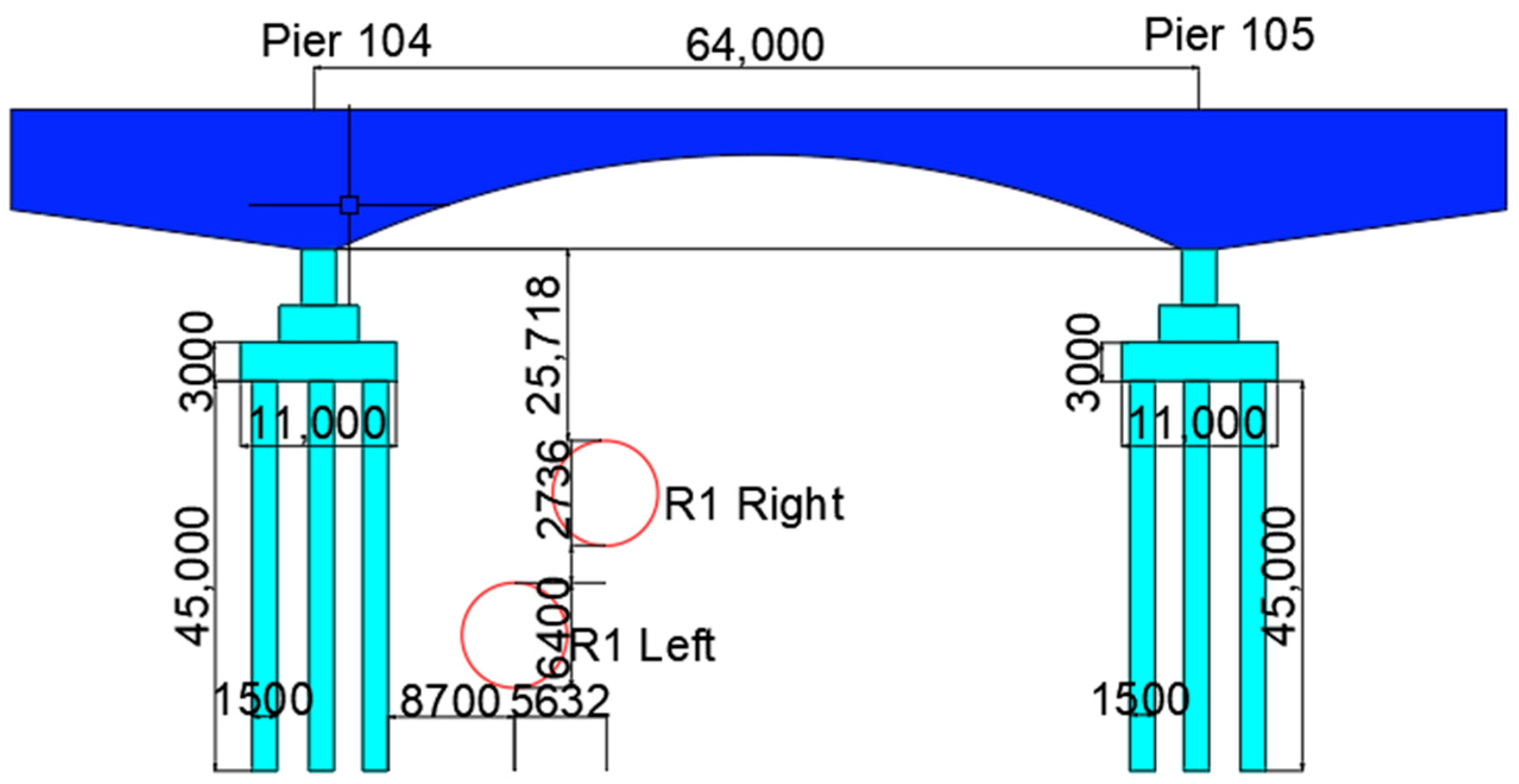
2. Project Overview
3. Mechanism of Disturbance and Deformation in the Stratum of Shield Tunnels Undercrossing High-Speed Rail Bridges
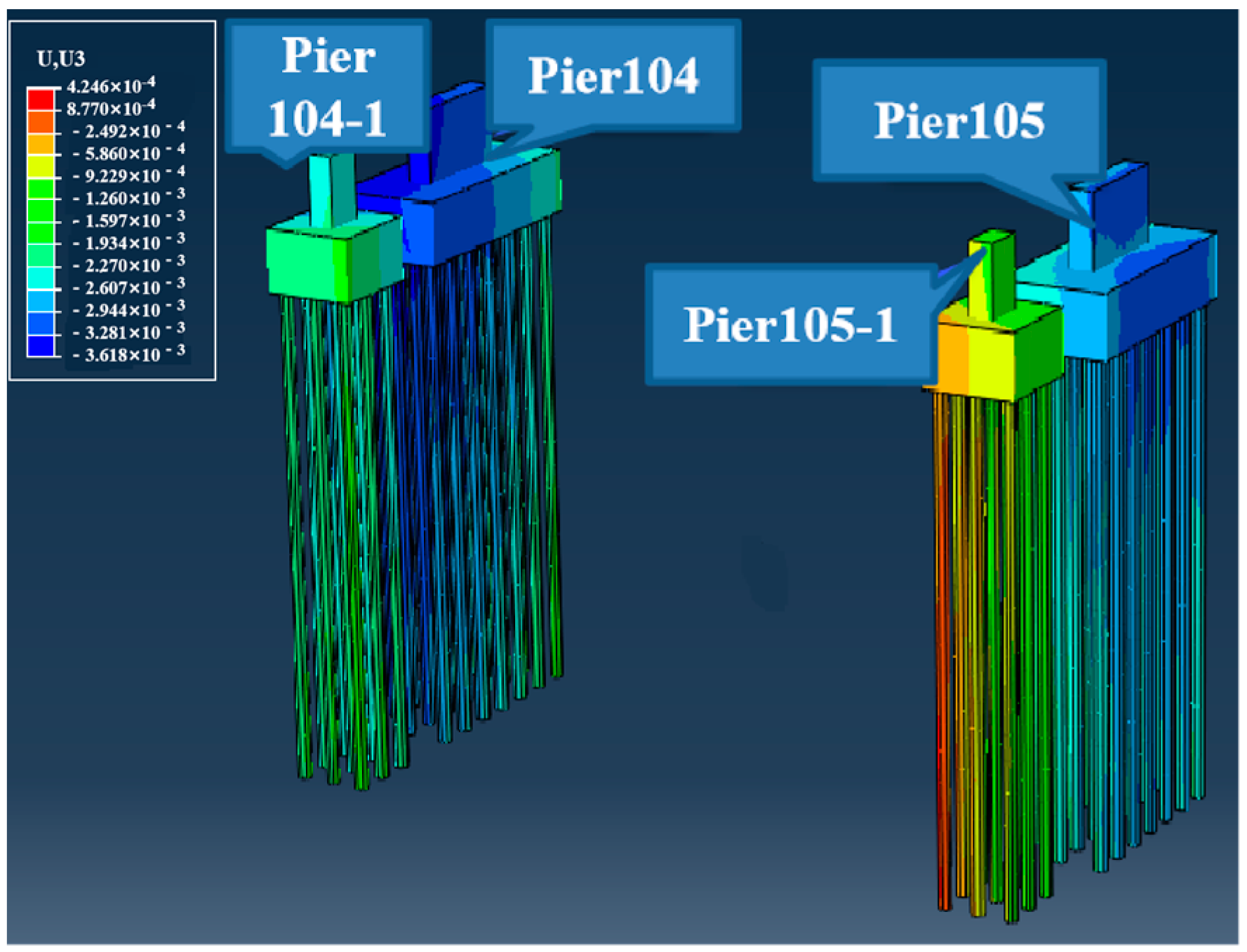
3.1. Model Establishment
3.2. Disturbance Simulation under Normal Excavation Conditions
3.3. Mechanism of Pile–Soil Interaction during Shield Tunneling under Bridge Construction
3.4. Construction Factors Affecting Building Settlement
3.4.1. Soil Warehouse Pressure
3.4.2. Shield Tunneling Parameters
3.5. Safety Control Standards for High-Speed Railway Bridges
3.6. Construction Safety Control Technology
3.6.1. Setting up Isolation Piles and Sleeve Valve Pipes
- To ensure the safety of the Beijing–Shanghai high-speed railway during the construction and operation of shield tunnels, a pile foundation is installed between the bridge foundation of the Beijing–Shanghai high-speed railway and the shield tunnel (Φ 800@1000). Isolation and protection of drilled cast-in-place piles. The minimum distance between the isolation pile and the pile foundation of the existing Beijing–Shanghai high-speed railway bridge is 8.7 m, as shown in Figure 7. Considering the operational safety of the Beijing–Shanghai high-speed railway and the actual construction clearance on site, the drilling and grouting piles are selected to be drilled using a positive circulation drilling rig. The positive circulation drilling rig is 6 m high, with the most unfavorable position located under the bridge on the north side of the high-speed railway as an example. The drilling rig is 3.4 m away from the bottom of the beam, which does not pose a safety hazard to the crane. The pile foundation is drilled using manual lifting of steel cages, which are made in eight sections with a single section length of 5 m. The concrete pouring is carried out using the conduit method, which does not pose any safety hazards to the driver.
- Sleeve valve pipe construction. Sleeve valve pipes are used for grouting reinforcement in areas where drilling and grouting piles cannot be constructed due to pipelines. A rigid sleeve valve pipe with a diameter of 40 mm and a backward segmented grouting method were adopted. The grouting spacing between sleeve valve pipes is 1.2 m, and the grouting material within the reinforcement range is cement and water glass double liquid slurry. The sleeve valve pipe is drilled using a drilling rig, with two on the south side and a height of 5 m. The construction location is on the outside of the bridge and the west side of the high-voltage line, which does not pose a safety hazard to the driver.
3.6.2. Optimization and Control of Shield Tunneling Parameters
3.6.3. Grouting Control Technology
- (1)
- Synchronous grouting
- (2)
- Secondary grouting
3.6.4. Vehicle Support Technology
4. Analysis of On-Site Monitoring Results of Shield Tunneling under High-Speed Railway Bridges
4.1. Monitoring Plan
4.2. Analysis of Monitoring Results
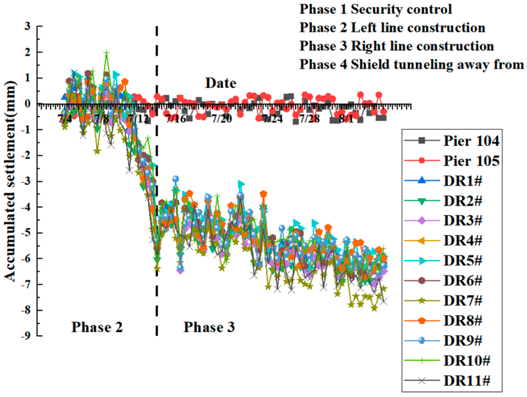
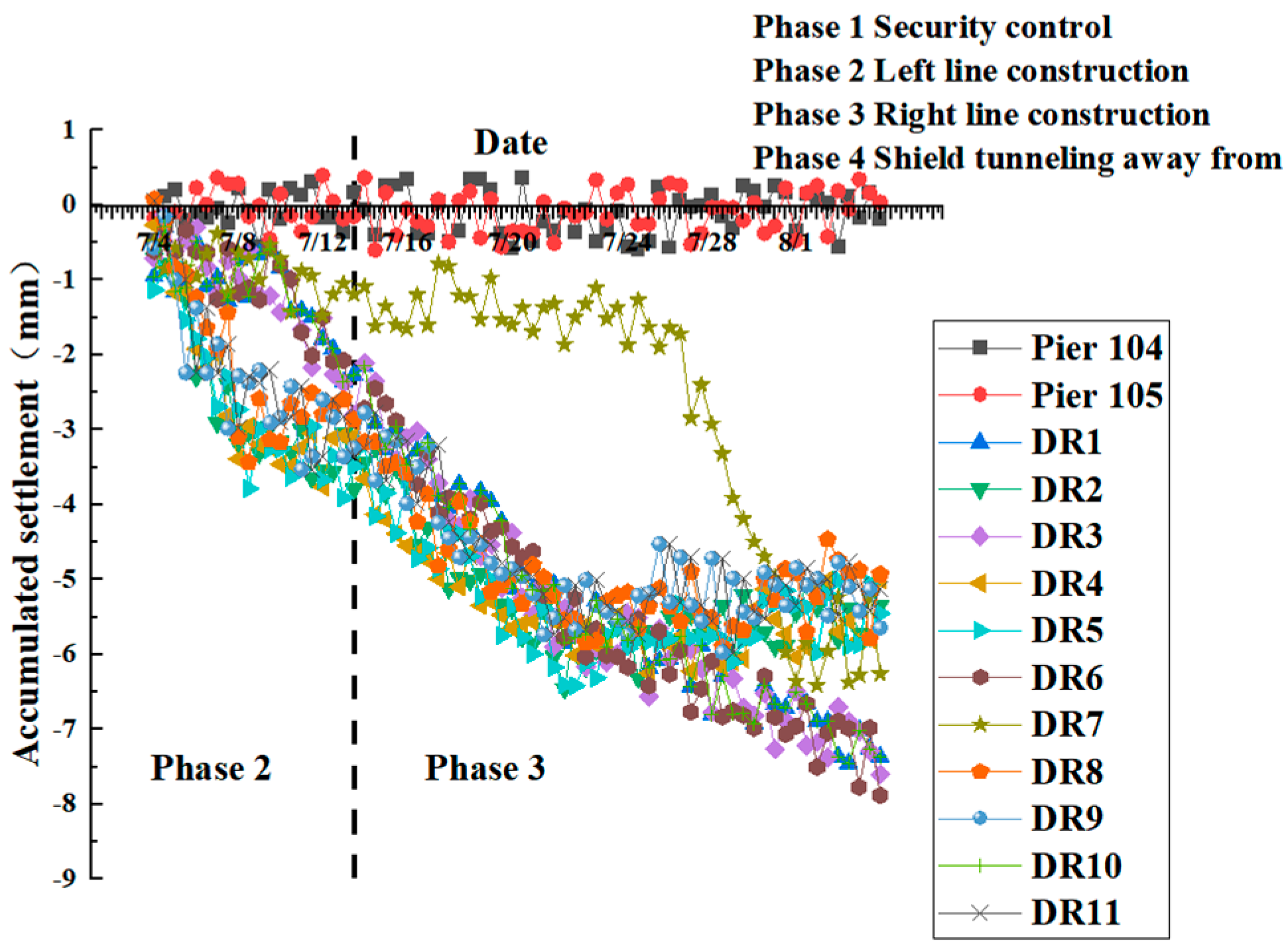
4.2.1. Analysis of Surface Subsidence Monitoring Results
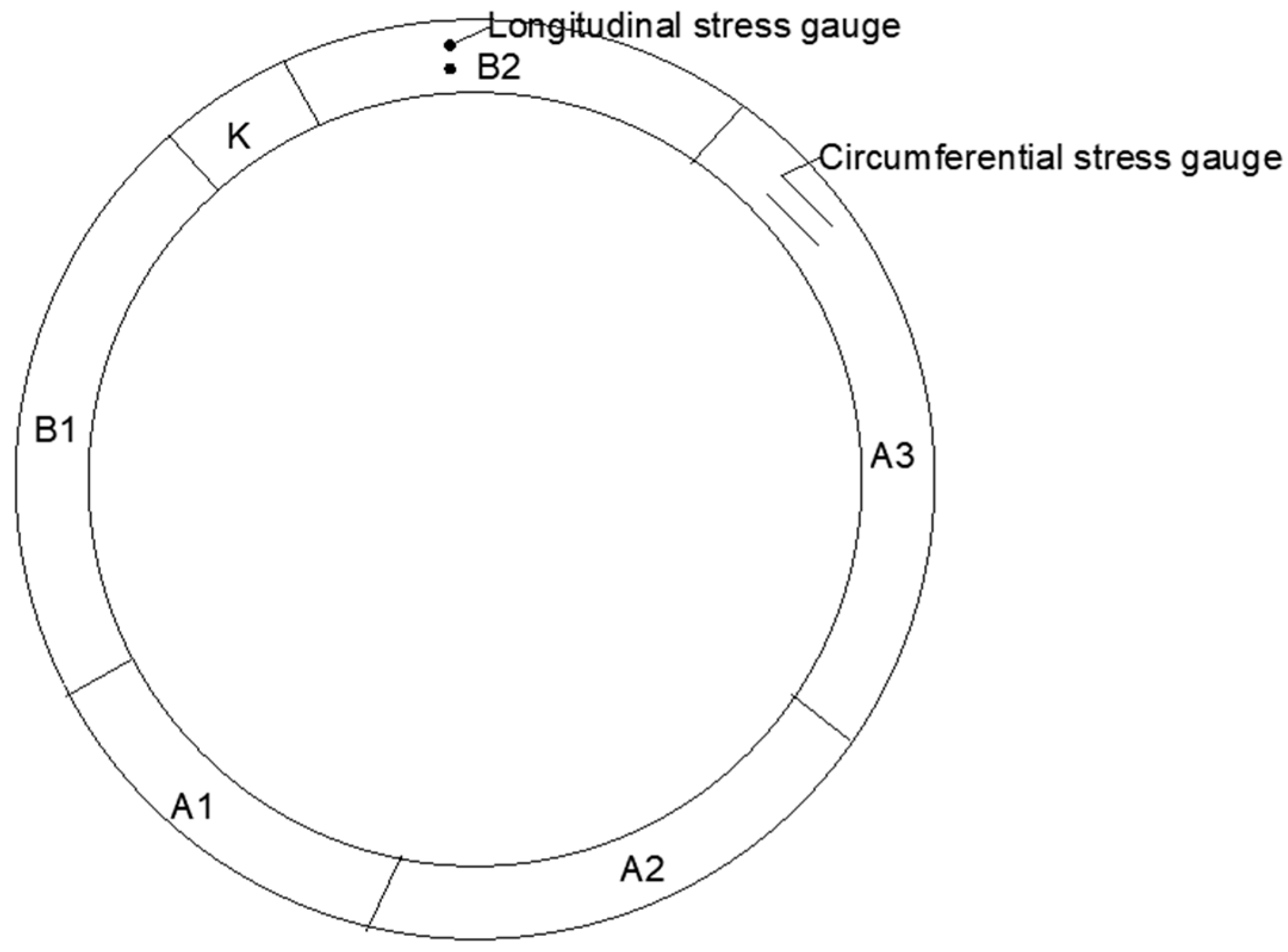
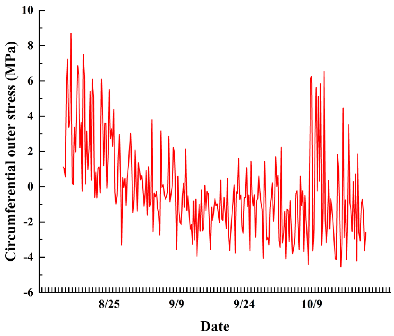
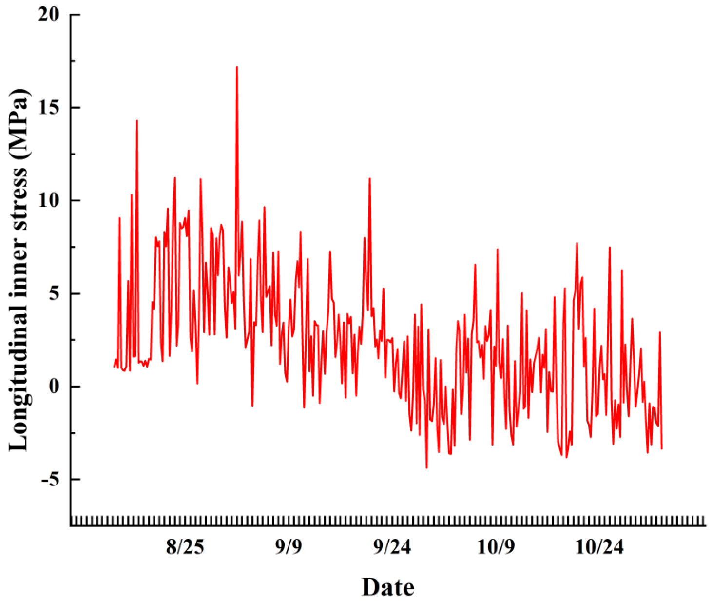
4.2.2. Analysis of Stress Monitoring Results for Pipe Segments
4.2.3. Analysis of Soil Pressure Monitoring Results
5. Conclusions
- Through disturbance simulation under normal excavation conditions, it was found that as the shield tunneling construction continued to advance, the cumulative settlement value of the bridge piers eventually exceeded the warning value by 1 mm. Security control measures must be taken.
- The settlement variation law of bridges is closely related to the spatial position of bridges and tunnels. In the area close to the tunnel, there is a significant change in surface settlement during the shield tunneling construction phase, and the force fluctuations on the pipe segments are significant. At this stage, the proportion of changes in surface settlement on the mainland to total settlement is relatively high. In areas far from the tunnel, significant changes in settlement occur during the tunneling phase of shield tunneling construction. The settlement variation during this stage accounts for a relatively high proportion of the total settlement.
- The monitoring results of shield tunneling through elevated bridges after implementing safety control measures show that the deformation of the bridge and surface settlement are significantly reduced. The stress situation of the pipe segments is within the allowable range and meets the safety control standards. Verified the effectiveness of security control measures.
- During construction, the grouting method can adopt a sequential hole pattern, and it is best to use the grouting construction method of interval jumping holes, gradual constraint, and first from bottom to top. During grouting construction, 3–5 leveling observation points should be set up on the surface for monitoring, and cracks and uplift are not allowed to occur on the ground. Once cracks and uplift occur on the ground, the grouting pressure and amount must be adjusted in a timely manner.
Author Contributions
Funding
Institutional Review Board Statement
Informed Consent Statement
Data Availability Statement
Conflicts of Interest
References
- Zhang, Z.Q.; He, C. Research on key technique of shield tunnel construction beneath adjacent existing highway tunnel. Rock Soil Mech. 2005, 26, 20–25. [Google Scholar]
- Fan, H.B. A study of the influence of shield tunnelling on surrounding environment based on the overlay model. Chin. J. Rock Mech. Eng. 2005, 1092. [Google Scholar] [CrossRef]
- Wang, M.Q.; Chen, S.H. 3-Dimensional non-linear finite element simulation of tunnel structure for moving-forward shield. Chin. J. Rock Mech. Eng. 2002, 21, 228–232. [Google Scholar] [CrossRef]
- Zhao, X.F.; Wang, C.M.; Sun, J.L.; Kong, X.L. Analysis of mechanical action of shield driving for approaching excavation. Rock Soil Mech. 2007, 21, 409–414. [Google Scholar]
- He, C.; Su, Z.X.; Zeng, D.Y. Influence of metro shield tunneling on existing tunnel directly above. China Civ. Eng. J. 2008, 91–98. [Google Scholar]
- Peck, R.B. Deep Excavation and Tunnelling in Soft Ground. State of the Art Report. In Proceedings of the 7th International Conference on Soil Mechanics and Foundation Engineering (Mexico), Mexico City, Mexico, 25–29 August 1969; pp. 225–290. [Google Scholar]
- Chen, C.L.; Zhao, C.L.; Wei, G.; Ding, Z. Prediction of soil settlement induced by double-line shield tunnel based on Peck formula. Rock Soil Mech. 2014, 35, 2212–2218. [Google Scholar]
- Lu, C.; Zhang, X.; Shi, B.; Jiang, J.; Lin, Z. Deformation in settlement and grouting remediation of thickened larger-diameter metro shield tunnel in soft soil: A case study. Case Stud. Constr. Mater. 2024, 20, e02736. [Google Scholar] [CrossRef]
- Wang, Q.; Xie, X.Y.; Huang, Z.H.; Qi, Y. Study of settlement troughs over quadruple-tube parallel shield tunnels crossing railway tracks. Chin. J. Rock Mech. Eng. 2017, S2, 4235–4243. [Google Scholar]
- Osman, A.S.; Mair, R.J.; Bolton, M.D. On the kinematics of 2D tunnel collapse in undrained clay. Geotechnique 2006, 56, 585–595. [Google Scholar] [CrossRef]
- Osman, A.S. Stability of unlined twin tunnels in undrained clay. Tunn. Undergr. Space Technol. 2010, 25, 290–296. [Google Scholar] [CrossRef]
- Wei, G. Research on theoretical calculation of long-term ground settlement caused by shield tunneling. Chin. J. Rock Mech. Eng. 2008, 27, 2960. [Google Scholar]
- Wei, X.J.; Zhang, J.J.; Zhang, S.M. Grope for shield tunnel construction induced ground maximal settlement. Rock Soil Mech. 2008, 29, 161–164. [Google Scholar]
- Wang, F.; Miu, L.C.; Li, C.L. Numerical analysis of shield tunnel settlement considering construction process. Chin. J. Rock Mech. Eng. 2013, z1. [Google Scholar] [CrossRef]
- Teng, L.; Zhang, H. Meso-macro analysis of surface settlement characteristics during shield tunneling in sandy cobble ground. Rock Soil Mech. 2012, 33, 186–195+205. [Google Scholar]
- Takahashi, K.; Fukazawa, N.; Hagiwara, T. Observational control of slurry shield tunnels with super close spacing under the nearby bridge abutments loads. Tunn. Undergr. Space Technol. 2004, 19, 390. [Google Scholar]
- Sirivachiraporn, A.; Phienwej, N. Ground movements in EPB shield tunneling of Bangkok subway project and impacts on adjacent buildings. Tunn. Undergr. Space Technol. Inc. Trenchless Technol. Res. 2012, 30, 10–24. [Google Scholar] [CrossRef]
- Basile, F. Effects of tunnelling on pile foundations. Soils Found. 2014, 54, 280–295. [Google Scholar] [CrossRef]
- Jongpradist, P.; Kaewsri, T.; Sawatparnich, A.; Suwansawat, S.; Youwai, S.; Kongkitkul, W.; Sunitsakul, J. Development of tunneling influence zones for adjacent pile foundations by numerical analyses. Tunn. Undergr. Space Technol. Inc. Trenchless Technol. Res. 2013, 34, 96–109. [Google Scholar] [CrossRef]
- Loganathan, N.; Poulos, H.G.; Stewart, D.P. Centrifuge model testing of tunneling-induced ground and pile deformations. Géotechnique 2000, 50, 283–294. [Google Scholar] [CrossRef]
- Leung, C.F.; Lim, J.K.; Shen, R.F.; Chow, Y.K. Behavior of Pile Groups Subject to Excavation-Induced Soil Movement. J. Geotech. Geoenviron. Eng. 2003, 129, 58–65. [Google Scholar] [CrossRef]
- Ong, D.E.L.; Leung, C.F.; Chow, Y.K. Behavior of Pile Groups Subject to Excavation-Induced Soil Movement in Very Soft Clay. J. Geotech. Geoenviron. Eng. 2009, 135, 1462–1474. [Google Scholar] [CrossRef]


| Rock Soil Stratification | Soil Thickness (m) | Modulus of Elasticity (MPa) | Poisson Ratio | Severe (kN/m3) | Internal Friction Angle (/°) | Cohesive Strength (kPa) |
|---|---|---|---|---|---|---|
| Miscellaneous fill ①1 | 5.9 | 4.3 | 0.35 | 18.5 | 18.3 | 20 |
| Fine sand ⑦ | 4.1 | 18 | 0.29 | 20.8 | 20 | 0 |
| Loess ⑦ | 9.8 | 5.6 | 0.26 | 19.1 | 23 | 43 |
| Silty clay ⑧ | 12.7 | 6.5 | 0.23 | 19.4 | 22 | 47 |
| Silty clay ⑩ | 10.3 | 7.8 | 0.25 | 19.2 | 24 | 50 |
| Pebble ⑩1 | 8.5 | 40 | 0.23 | 21.0 | 35 | 0 |
| Silty clay ⑪ | 13 | 8.1 | 0.28 | 19.4 | 24 | 52 |
| Pebble ⑪1 | 15.7 | 45 | 0.23 | 21.2 | 40 | 0 |
| Title | Severe (kN/m3) | Elastic Modulus (GPa) | Poisson’s Ratio | Outside Diameter (m) | Inner Diameter (m) | Thickness (m) |
|---|---|---|---|---|---|---|
| Tunnel lining | 30 | 40 | 0.3 | 6.4 | 6 | 0.2 |
| Isogenerational layer | 20 | 0.03 | 0.25 | 6.4 | 6.475 | 0.075 |
| Shielding | 80 | 210 | 0.3 | 6.4 | 6 | 0.2 |
| Bridge piers and piles foundations | 30 | 35 | 0.3 | / | / | / |
| Monitoring Projects | Yellow Alert | Orange Alert | Red Alert | Limit | ||||
|---|---|---|---|---|---|---|---|---|
| Change Rate (mm/Day) | Accumulated Settlement (mm) | Change Rate (mm/Day) | Accumulated Settlement (mm) | Change Rate (mm/Day) | Accumulated Settlement (mm) | Change Rate (mm/Day) | Accumulated Settlement (mm) | |
| Bridge pier settlement | ±0.36 | ±0.5 | ±0.45 | ±0.75 | ±0.54 | ±0.9 | ±0.9 | ±1.0 |
| Surface subsidence | ±5 | ±10 | ±8 | ±15 | ±10 | ±18 | ±15 | ±20.0 |
| Parameter | Trial excavation standards |
| Soil pressure | Upper soil pressure 1.5~2.0 bar |
| Total thrust | 800~2000 T |
| Knife disc torque | 1000~2500 KN·m |
| Advance speed | 30~50 mm/min |
| Knife disc speed | 0.8~1.0 rpm |
| Synchronous grouting pressure | 0.1~0.3 MPa |
| Synchronous grouting volume | 5.2 m3 |
| Excavated quantity | Not more than 56 m3 |
Disclaimer/Publisher’s Note: The statements, opinions and data contained in all publications are solely those of the individual author(s) and contributor(s) and not of MDPI and/or the editor(s). MDPI and/or the editor(s) disclaim responsibility for any injury to people or property resulting from any ideas, methods, instructions or products referred to in the content. |
© 2024 by the authors. Licensee MDPI, Basel, Switzerland. This article is an open access article distributed under the terms and conditions of the Creative Commons Attribution (CC BY) license (https://creativecommons.org/licenses/by/4.0/).
Share and Cite
Yang, T.; Peng, X.; Huang, X.; Liu, B.; Li, K.; Zhang, J.; Li, Y.; Wen, T. Safety Control Technology and Monitoring Analysis for Shield-Tunnel-Stacked Underpass High-Speed Rail Bridge Excavation. Appl. Sci. 2024, 14, 1699. https://doi.org/10.3390/app14051699
Yang T, Peng X, Huang X, Liu B, Li K, Zhang J, Li Y, Wen T. Safety Control Technology and Monitoring Analysis for Shield-Tunnel-Stacked Underpass High-Speed Rail Bridge Excavation. Applied Sciences. 2024; 14(5):1699. https://doi.org/10.3390/app14051699
Chicago/Turabian StyleYang, Taihua, Xiaoxiang Peng, Xing Huang, Bin Liu, Kejin Li, Jianyong Zhang, Yixiang Li, and Tian Wen. 2024. "Safety Control Technology and Monitoring Analysis for Shield-Tunnel-Stacked Underpass High-Speed Rail Bridge Excavation" Applied Sciences 14, no. 5: 1699. https://doi.org/10.3390/app14051699