Article

Building an Information Modeling-Based System for Automatically Generating the Assembly Sequence of Precast Concrete Components Using a Genetic Algorithm

1
Department of Architectural Engineering, Ajou University, Suwon 16499, Republic of Korea
2
Department of Construction Management, Dalian University of Technology, Dalian 116024, China
*
Author to whom correspondence should be addressed.
Appl. Sci. 2024, 14(4), 1358; https://doi.org/10.3390/app14041358
Submission received: 11 January 2024 / Revised: 1 February 2024 / Accepted: 2 February 2024 / Published: 7 February 2024

Abstract

:
Facing a significant decrease in economic working processes, Off-Site Construction (OSC) methods have been frequently adopted in response to challenges such as declining productivity and labor shortages in the construction industry. Currently, in most OSC applications, the assembly phase is traditionally managed based on the personal experience and judgment of the site managers. This approach can lead to inaccuracies or omissions, particularly when dealing with a large amount of information on large, complex construction sites. Additionally, there are limitations in exploring more efficient and productive alternatives for rapidly adapting to changing on-site conditions. Given that the assembly phase significantly affects the OSC productivity, a systematic management approach is crucial for expanding OSC methods. Some initial studies used computer algorithms to determine the optimal assembly sequences. However, these studies often focused on geometrical characteristics, such as component weight or spatial occupancy, neglecting crucial factors in actual site planning, such as the work radius and component installation status. Moreover, these studies tended to prioritize the generation of initial assembly sequences rather than providing alternatives for adapting to evolving on-site conditions. In response to these limitations, this study presents a systematic framework utilizing a Building Information Modeling (BIM)–Genetic Algorithm (GA) approach to generate Precast Concrete (PC) component installation sequences. The developed system employs Genetic Algorithms to objectively explore diverse assembly plans, emphasizing the flexibility of accommodating evolving on-site conditions. Real on-site scenarios were simulated using this framework to explore multiple assembly plan alternatives and validate their applicability. Comprehensive interviews were conducted to validate the research and confirm the system’s potential contributions, especially at just-in-time-focused PC sites. Acknowledging a broader range of variables such as equipment and manpower, this study anticipates fostering more systematic on-site management within the context of a digitized construction environment. The proposed algorithm contributes to improving both productivity and sustainability of the construction industry by optimizing the management process of the off-site construction projects.

1. Introduction

The construction industry faces multifaceted challenges, notably declining productivity and labor shortages, prompting a shift towards Off-Site Construction (OSC) methodologies. OSC methods, which encompass factory production and on-site assembly, have attracted attention for their potential to mitigate challenges by enhancing productivity and reducing labor demands [1,2]. Within this domain, Prefabricated Prefinished Volumetric Construction and Prefabricated Concrete structures have emerged as promising solutions for diverse architectural needs [3,4].
The effective management of processes, component supply chains, and material resources is crucial for boosting productivity in OSC projects and contributing to achieving the UN Sustainability Development Goals (SDGs) [5,6]. Assembly planning at PC sites is a key factor that directly influences productivity [7]. Failure to consider prefabricated building characteristics and adopting impractical schedules can lead to project delays and increased costs [8]. In prefabricated building projects, determining the assembly sequence of the components is crucial for optimizing plans and efficiently coordinating equipment [9]. A comprehensive consideration of on-site variables is essential for adapting to these conditions [10]. For instance, in Reinforced Concrete (RC) composite construction sites, variations in the RC process owing to weather, unregulated concrete quantities, cement shortages, and same-day concrete delivery cancellations often lead to adjustments in the initially planned PC assembly sequence.
The traditional approach for determining assembly sequences relies heavily on the practical knowledge of on-site managers and often lacks standardized evaluation criteria [9]. However, the complexities of larger and more intricate construction sites increase the likelihood of information mishandling, highlighting the need for a structured approach. Building Information Modeling (BIM) is useful in systematically managing a variety of project information [11]. Using Artificial Intelligence (AI) technology, the information of the building elements can be effectively visualized in the BIM model. This enhanced technology can allow project participants to manage the actual status of the building on a real-time basis [12]. This study aims to provide objective decision-making support for planning assemblies on evolving PC sites. It seeks to move away from subjective methods and envision adaptable assembly plans suitable for dynamic construction environments. Previous research has mainly focused on identifying the factors that cause delays in component assembly at construction sites. For instance, Wuni et al. (2022) [13] highlighted weather conditions and communication gaps among stakeholders as contributors to assembly delays at modular construction sites. Despite numerous studies examining the overall construction progress in prefabricated settings, there remains a noticeable gap in research that specifically investigates on-site assembly factors.
Historically, scheduling methods such as the Critical Path Method (CPM) and Program Evaluation and Review Technique (PERT) have been crucial; however, they face limitations owing to resource constraints, requiring subsequent optimization for practical use [14,15]. Recent explorations of metaheuristic algorithms, notably Genetic Algorithms (GA), have shown promise in prefabricated construction. These algorithms automate assembly planning and reduce the construction complexity [16,17]. However, current research mainly focuses on generating initial schedules and overlooks adaptation to on-site conditions, thereby limiting its applicability in real-world scenarios.
On the other hand, in a current situation where a sustainability issue is emphasized, the construction practice requires a reduction in the resources required for the project. As a result, resource efficiency in the construction can have a significant impact on the sustainable future [18,19].
This study addresses the challenges present in larger construction sites by creating a systematic methodology for generating and managing assembly sequences using site-specific information with the aim of avoiding gaps and errors. To fill this research gap, this study aimed to provide alternative assembly plans tailored specifically to on-site conditions, easing adaptation to ever-changing dynamics. The hypotheses formulated here, which focus on utilizing Genetic Algorithms and developing a visualized system for assembly planning, are intended for validation through the exploration of critical factors in assembly planning within actual construction sites. Constructing a comprehensive system built upon insights gathered from in-depth interviews with a diverse array of on-site stakeholders is the cornerstone of this study’s methodology for deriving optimal assembly sequences ready for practical implementation.

1.1. Literature Review

1.1.1. Assembly Phase Considerations in the OSC Environment

This study undertook an extensive literature review to identify the essential elements and potential risks inherent in the assembly phase, which is critical for developing assembly sequences that ensure minimal interference and optimal workflow at building sites. This phase of prefabricated construction is largely concerned with the installation of various components, primarily concentrated on crucial equipment, such as cranes. Consequently, effective resource allocation, including equipment and labor, is vital [15].
Gong et al. (2019) [20] employed Social Network Analysis to identify the constraints within prefabricated construction assemblies, effectively establishing a model to illuminate the intricate interrelationships among these constraints. The risks identified during on-site assembly include communication errors, improper installation planning, and spatial interference among workers and spaces. In particular, the absence of an optimal installation plan significantly hampers the derivation of efficient assembly sequences. Ji et al. (2018) [21] utilized a Decision-Making Trial and Evaluation Laboratory model alongside the Analytic Network Process technique to discern and prioritize delay factors in prefabricated construction. Their findings underscored the profound impact of inappropriate construction planning, transportation errors, and communication discrepancies between stakeholders during the assembly phase. Combining these influential studies highlights the crucial role of defining assembly sequences. This underscores the necessity for comprehensive planning that integrates both manpower and equipment allocation, while managing spatial interference to create efficient assembly sequences. This alignment is pivotal for optimizing the assembly phase, ultimately improving workflow efficiency and reducing potential disruptions at construction sites.

1.1.2. Methodology for On-Site Construction Planning Automation and Optimization

To investigate the methods related to creating assembly sequence plans, this study examined the algorithms and approaches used for automating scheduling and optimization in construction. Traditional methods such as the CPM and PERT acknowledge the precedence relationships between activities but face challenges in integrating constraints such as limited labor and equipment [15].
Recent research has highlighted the efficacy of algorithms for automated scheduling optimization. Zhu et al. (2023) [16] innovatively leveraged a game engine to create a reconfigurable assembly simulator by deploying Deep Reinforced Learning for automated assembly plans using robots on robot-based construction sites. Hong et al. (2023) [22] employed a Graph-Based Automated Scheduling method, rearranging construction schedules by extracting activity characteristics to maximize efficiency in terms of cost and time. Moreover, Building Information Modeling (BIM) serves as a pivotal tool for extracting inter-component relationships and determining optimal assembly schedules, as demonstrated by Liu et al. (2014) [23]. Additionally, metaheuristic algorithms such as Ant Colony Optimization (ACO), Particle Swarm Optimization (PSO), and GA play significant roles in schedule optimization within the construction environment [24]. ACO mimics the food-searching behavior of ants by leaving pheromones on efficient paths, effectively modeling the time–cost relationship in construction optimization [25]. PSO, inspired by the social behavior of birds, amalgamates evolutionary optimization techniques to find optimal solutions by amalgamating information from various sources [26]. These methods perform iterative calculations within specified constraints and generate multiple alternatives that mirror the intricate nature of construction environments to derive optimal schedules. However, the obtained optimal values tend to converge prematurely, leading to local optimal points [27].

1.1.3. Genetic Algorithm-Based Automated Assembly Planning

The GA is a widely applied construction methodology that aims to optimize costs and time [28,29,30]. It showcases efficiency in swiftly attaining optimal solutions by utilizing objective functions for straightforward problem-solving [31]. Moreover, the versatility of the GA enables the exploration of diverse solutions and addresses multi-objective construction scheduling problems through various search strategies [32,33]. Derived from natural selection principles, the GA involves stages of selection, crossover, and mutation, driving the iterative evolution of initially random genes towards a form best suited for the defined objective function [17,24]. The selection process typically employs the roulette-wheel method, favoring individuals with higher fitness as potential parents [9]. The essence of the GA lies in explicitly defining the objective function of the problem, allowing for the gradual evolution of genes to align with the intended optimization objective.
As stated in Section 1.1.2, GA emerged prominently within metaheuristic methods for optimizing schedules, particularly in determining optimal assembly sequences for components. Faghihi et al. (2014) [17] based their methodology on BIM, extracted information from the model, and defined a Matrix of Structurability Constraints. They employed a GA to automatically generate sequences, ensuring that the prefabricated components were installed in a structurally stable order. Wang et al. (2018) [7] investigated this domain by combining BIM with a novel technique called the Improved Genetic Algorithm, which was specifically designed to improve Assembly Sequence Planning. They envisioned each precast concrete component as a gene in the algorithm, focusing on precast concrete components. They generated ideal assembly sequences by methodically analyzing geometric properties such as weight, spatial occupancy, and inter-component interference, and then presented visual results via the BIM model. Similarly, Huang et al. (2022) [34] explored optimization strategies by employing a Multilevel Elitist Genetic Algorithm. Their focus extended beyond rectifying geometric characteristics to resolve the interference in paths related to precast components. Their method aimed to minimize assembly disruptions by intricately refining pathways and geometric attributes using sophisticated genetic algorithmic techniques. Acknowledging the inherent limitations of the GA in converging toward suboptimal solutions in specific scenarios, Liu et al. (2023) [9] introduced an annealing algorithm, which is a strategic enhancement for refining assembly sequences. This augmentation aims to mitigate the convergence issues observed in GA applications, thereby further optimizing the assembly sequence.

1.2. Limitations of Previous Studies

Previous research primarily focused on determining the optimal assembly sequences for individual components to minimize construction challenges using BIM and GA. However, these studies were confined to generating assembly sequences based on physical characteristics, such as component weight and spatial occupancy, overlooking critical considerations for on-site assembly planning, such as the working radius and task interference. Consequently, their practical implementation faces challenges, and experiments typically involve a limited number of components. Moreover, most studies have focused on creating initial assembly sequences and have overlooked the necessity of adapting these sequences to dynamic on-site conditions. In this study, a combination of BIM and GA was employed to develop a system that incorporates on-site assembly requirements, going beyond the scope of planning initial assembly sequences during the construction phase. The objective was to create a system capable of adjusting to evolving on-site conditions and visualizing the final application in the field. It is assumed that all the components required for assembly are readily available, and the specific details regarding hoisting, except for the tower crane’s location information, are not addressed. This research focused on generating assembly plans, emphasizing the sequence of assembly rather than determining the initial components of the hoist.

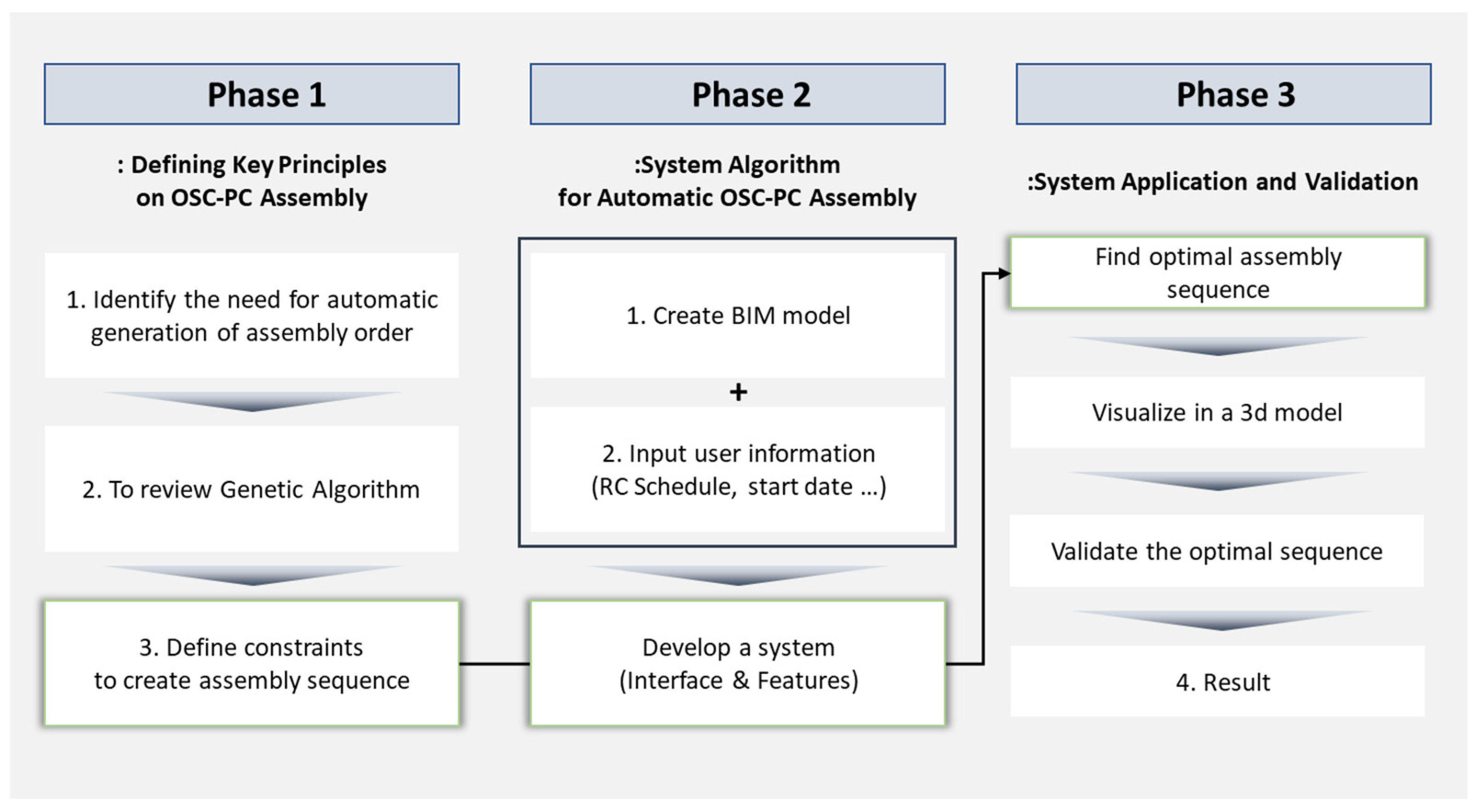
2. Materials and Methods

An in-depth interview was conducted in a construction jobsite of K construction company, located in Seoul, Korea. The interviewees were requested to provide key influence factors in the PC assembly phase. They were also equipped with drawings and project manuals. Then, the real case project was selected and rigorously studied by generating a Building Information Modeling (BIM) model. Subsequently, the relevant information of all the PC elements was extracted using Dynamo 2.19.3 software. The developed algorithm was then applied to this dataset to validate the results and assess the feasibility of the proposed method. This study adopted a sequential framework consisting of three key stages to comprehensively address the development and implementation of assembly sequences for PC components using the BIM-GA approach. The three phases are:
  • Establishment of Principles for Assembly Sequence Generation: This initial phase focuses on developing a comprehensive system framework integrating BIM and GA. The objective of this study is to understand the influence of various complex constraints and principles on the assembly sequence generation process.
  • Development of an on-site assembly sequence automation interface: The second phase involves the development of a system interface tailored for practical on-site applications. This includes the creation of software applications, definition of system functionalities, and integration of relevant aspects to facilitate real-time utilization.
  • Validation and Adaptability Assessment in On-site Applications: In the final phase, the research outcomes were applied in real on-site scenarios to validate the efficacy and versatility of the automated assembly sequence system. This involves the exploration of diverse assembly sequences and simulations to determine the adaptability of the system to evolving on-site conditions.
Figure 1 shows an overview of each phase. Detailed explanations of each phase are provided in the following sections.

3. Results

3.1. Phase I: Defining PC On-site Assembly Optimization Principles via BIM-GA Hybrid System

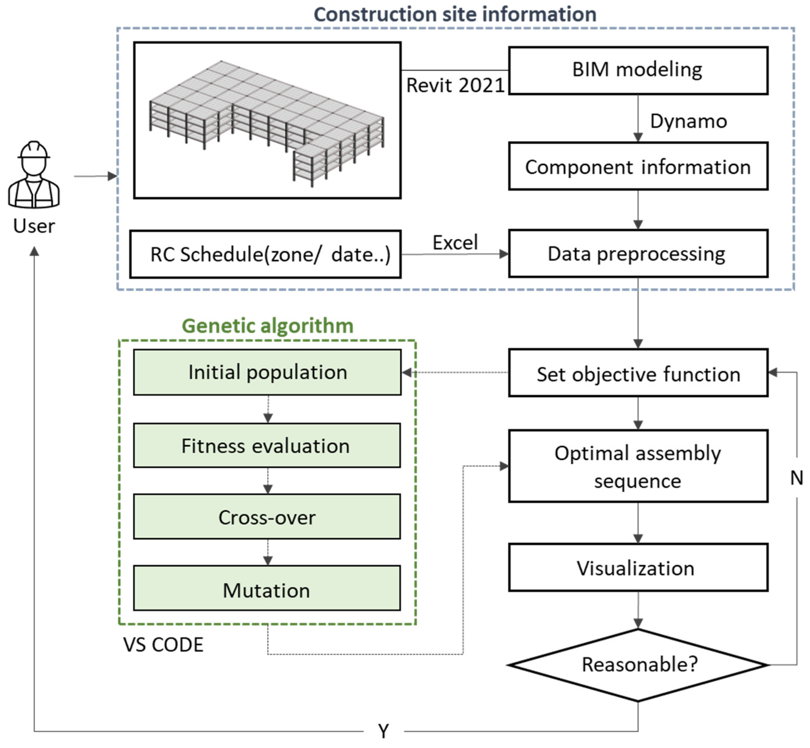
3.1.1. System Framework

The proposed system framework, depicted in Figure 2, integrates two key input types: BIM information for the site and schedules of concurrent construction processes (e.g., RC processes). When BIM information is inserted, the Dynamo add-in program in Revit is employed to extract information for each PC component. The extracted details include information such as the zone, level, and coordinates (x, y, z) of each component, which are directly utilized to generate the assembly sequence. To generate an assembly sequence for PC components, it is essential to consider not only PC processes but also to check for interference with other on-site construction processes, such as RC processes. For this purpose, information containing schedules and location details of other construction processes (RC) must be inserted. Once these two types of on-site information are inputted, a data preprocessing stage is performed for algorithm utilization. The GA is then executed according to a defined objective function to obtain an optimal assembly sequence. The resulting optimal assembly sequence is visualized, allowing for an assessment of its applicability on site and optimizing structured data as a basis for decision-making for on-site managers regarding assembly plans.

3.1.2. Constraints of Optimizing Assembly Sequence

To improve productivity in construction, effective control of influencing factors such as labor and equipment is essential [35]. In practical construction settings, assembly plans are developed based on specific considerations to enhance operational efficiency. To gain insight into the specific considerations of real sites, interviews were conducted with stakeholders at a PC construction site. The interviewees, including three construction engineers, one administrative team leader, and one site management director, provided insights into the considerations during component assembly and identified the factors contributing to delays. Focus group interviews were conducted both on site in February 2023 and through subsequent email exchanges in June, unveiling the critical factors influencing assembly sequences:
  • Time-Efficient Sequencing: Sequential installation of similar components, typically in the order of columns, beams, and slabs within specific zones, optimizing workflow dependencies.
  • Minimized delays and movement: Adjacent components within the work area are prioritized to save waiting times and unnecessary equipment and labor movements, ensuring efficient installation. The validation of component adjacency within a feasible radius is pivotal.
  • External Factors and Coordination: Weather fluctuations and other external elements can disrupt project schedules. Daily coordination in precast concrete assemblies, particularly during crane activity, is critical. Factors such as component damage, delivery delays, and on-site hindrances must be considered.
Based on the findings from a Focus Group Interview (FGI), this study aimed to derive an assembly sequence considering the following factors influencing the on-site workflow: 1, Complexity of tasks; 2, Adjacency within the working radius; and 3, Interference with other construction activities. Typically, planning is conducted by floor levels, so as a result, this study restricts the scope to creating assembly plans within the same floor while considering these three constraints. The generated assembly sequence verifies the compliance of each item for consecutive components. If violations occur, penalty scores are assigned to minimize these scores and derive the most efficient assembly sequence (Figure 3). Further details on each item are outlined below.

3.1.3. Complexity of Works

In construction projects with repetitive tasks, streamlining the work duration involves performing identical tasks consecutively and expediting time-consuming activities [9]. PC construction sites tend to install identical components consecutively to ensure workspace clearance and to prevent collisions. However, installing different component types results in longer waiting times because of the additional tasks associated with each component type. Therefore, in such situations, streamlining the work pattern to enhance the overall work speed can be achieved by prioritizing the installation of column components, which involves time-consuming tasks owing to the abundance of additional tasks before and after installation. Thus, in this study, the installation of elements of the same type was considered to determine whether the same type of component was installed repeatedly. Additionally, the study evaluates which component precedes another, assigns a complexity score of 0 if the same task is consecutive, and scores of 1, 2, and 3 for column, beam, and slab precedences, respectively, based on the time each component type takes. The sum of these Cps values is further formalized as A, representing the total Complexity Penalty Score.
A = i = 1 n 1 C p s i , i + 1
Cps i , i + 1 = 0 , when   ith   and i + 1 th   are   same   element   type 1 , when   ith   is   column   and i + 1 th   is   beam   or   slab 2 , when   ith   is   beam   and i + 1 th   is   column   or   slab 3 , when   ith   is   slab   and i + 1 th   is   column   or   beam
  • A = sum of penalty score of complexity
  • C p s i , i + 1 = complexity penalty score between ith and i + 1th components of the assembly sequence
  • n = the number of components

3.1.4. Adjacency of Works

Construction plans that reflect the working radius and workflow of workers enhance the efficiency of the construction progress [17]. When planning an assembly sequence of elements, it is crucial to determine whether these aspects have a rational assembly order. Therefore, it is reasonable to recognize the level of adjacency of the subsequent PC elements, based on the precedent PC element. In this study, the distances between the elements are utilized to prioritize the installation of adjacent elements. Using the Euclidean method to calculate distances based on the centroids of the elements in the BIM, both the horizontal and diagonal distances are considered. The extracted positional information of the elements is then used to assign a penalty value of zero when the distance between consecutive elements decreases or remains constant. When the distance increases, the penalty value is assigned as the ratio of the distance, defined as the Adjacency Penalty Score. The sum of these Aps values is further formalized as B, representing the total Adjacency Penalty Score. This approach enhances the workflow by ensuring that the adjacent elements are installed from the closest ones, as expressed in (2).
B = i = 1 n 2 A p s i , i + 1  
A p s i , i + 1 = {     0 ,                                   d i + 1 d i       d i + 1 d i ,                         d i + 1 > d i
  • B = sum of penalty score of adjacency
  • A p s i , i + 1 = adjacency penalty score between ith and i + 1th component in the assembly sequence
  • d i =distance between ith and i + 1th component in the assembly sequence
  • n = the number of components

3.1.5. Interference of Works

Construction projects, which are characterized by the simultaneous and consecutive execution of numerous tasks within a limited time and space, face a high probability of temporal and spatial interference among the tasks (Kang et al., 2001) [36]. This interference is the primary cause of reduced productivity at construction sites (Vaux et al., 2018) [37]. Hence, it is imperative to minimize the interference in the workspace to ensure efficient construction progress (Moon, 2014) [38]. Furthermore, various challenges such as delays in element delivery or damage often render the installation of scheduled elements unfeasible because of non-compliance with quality standards. This study aimed to comprehensively assess such situations to determine the feasibility of element installation.
To evaluate the feasibility of element installation at sites conducting composite construction, including the RC process, essential information such as installation dates and location details for each PC element is crucial. In addition, the schedule of the RC process must be incorporated into the analysis. By setting the assembly schedule based on the sequence of the PC element assembly, potential time–space conflicts are identified by considering the RC process’s time and location information. In cases in which interference with other processes occurs, a penalty score of 1 is assigned; otherwise, a score of 0 is assigned, defined as the Interference Penalty Score (IPS). The sum of the Ips values is formalized as C, representing the total Interference Penalty Score, as expressed in Formula 3.
C = i = 1 n I p s i
I p s i = { 1 ,                             w h e n   i t h   c o m p o n e n t   i s   i n t e r f e r e d   0 ,               w h e n   i t h   c o m p o n e n t   i s   n o t   i n t e r f e r e d
  • C = sum of penalty score of interference
  • I p s i = interference penalty score per component in the assembly sequence
  • n = the number of components
Finally, the assembly sequence is designed to optimize the overall workflow by minimizing the combined penalty scores associated with the three factors mentioned above, as expressed in Equation (5). However, considering the different scales of penalty scores, there may be a potential bias in prioritizing constraints (Kim et al., 2021) [39]. Additionally, the fitness calculations in Equation (5) could not accommodate a value of zero. To address this issue, a strategy is employed using cumulative distribution functions with averages and standard deviations from the A, B, and C values. This transformation aims to standardize and assess the deviation of each value from its mean. Subsequently, these values are represented in terms of A′, B′, C′. Finally, specific weights α, β, γ are assigned to each constraint in Equation (4) to allow constraint prioritization based on the specific conditions of the construction site.
P = α A + β B + γ C = α i = 1 n 1 C p s i , i + 1 + β i = 1 n 2 A p s i , i + 1 + γ i = 1 n I p s i  
  • P = composite penalty score of all PC components
  • α = weight of complexity (constraint 1)
  • β = weight of adjacency (constraint 2)
  • γ = weight of interference (constraint 3)
  • n = The number of components
F i t n e s s = 1 / P   ( P 0 )
  • P = composite penalty score of all PC components

3.2. Phase II: Development of an Automatic Assembly Sequence Generation System Based on the PC Construction Site

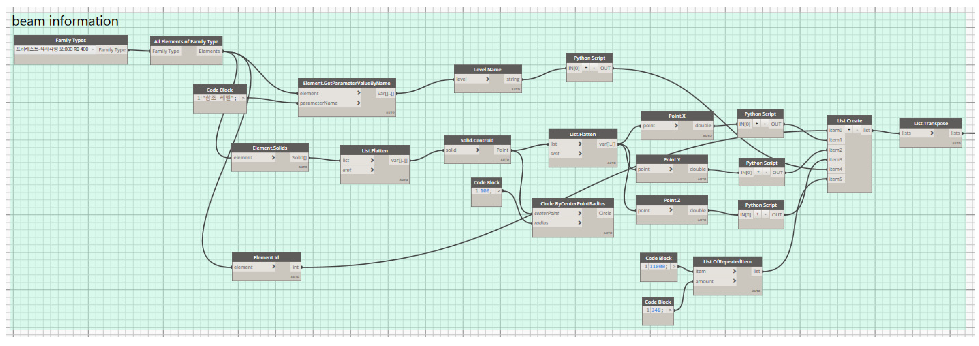
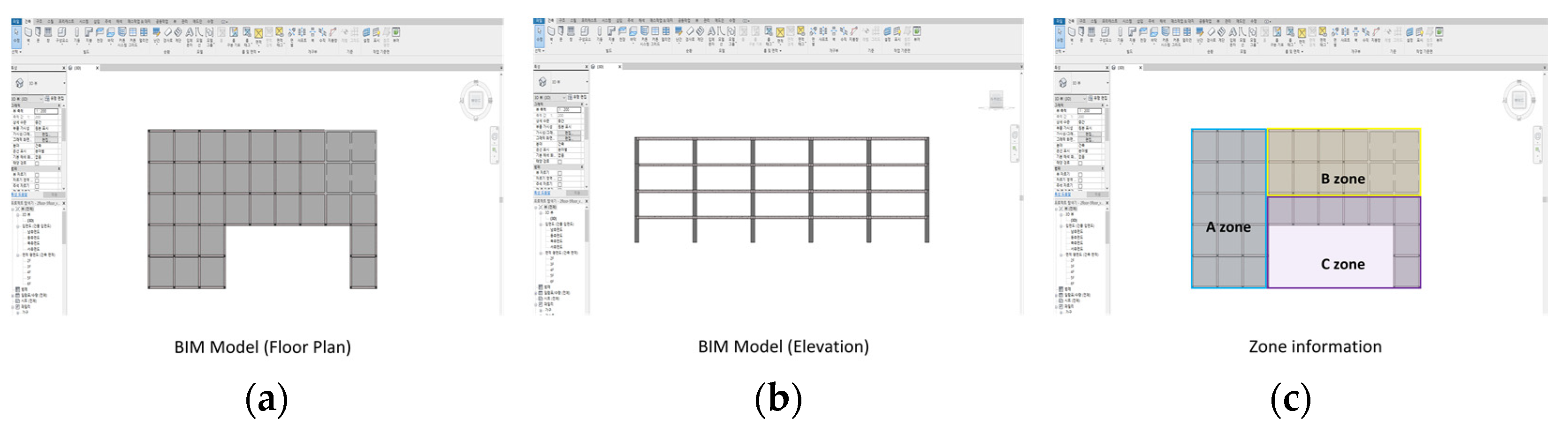
3.2.1. PC Site Modeling and Component Information Extraction

The research overview, as depicted in Figure 1, was initiated by creating a BIM representation of the PC construction site. A comprehensive BIM (Figure 4a) was created using Revit 2021. Subsequently, Dynamo, an add-in program, facilitated the identification of the centroids for the columns, beams, and slabs, thereby extracting precise coordinate information. The visualization as shown in Figure 4b showcases the centroids highlighted for each component.
Figure 5 illustrates the systematic process employed to extract component information. Dynamo employs nodes interconnected by wires to build a programming script. Beginning with the ‘family type’ node located in the top-left corner of Figure 5, all modeled beam objects were extracted. This was followed by establishing centroids for each object by sequentially connecting the ‘solid’ node and then linking the ‘solid.centroid’ node. Further nodes, ‘x’, ‘y’, and ‘z’, were connected to extract precise x, y, and z coordinates for each component’s centroid.
After this process was performed for the columns, beams, and slabs, the information for each object comprising the 3D model was extracted. The extracted information was formatted as an Excel file. Additionally, to discern the assembly sequence for the components, the zone information necessary for each assembly was included in Excel to build the component-specific data. An example of the extracted information is presented in Table 1, encompassing the component ID, x, y, and z coordinates, and floor information.
This research not only aimed to determine the initial sequence for assembling the construction elements but also intended to adapt to changes in the construction site. To achieve this adaptability, a method is required to select elements for which assembly sequences require determination among all the elements constituting the building. Elements marked with an ‘Installation’ column value of 0 in the information table (Table 1) were identified as not yet installed. Thus, the assembly sequence was generated specifically for these elements with an installation value of 0. By assigning 0 to certain elements, the model represents changes in the construction conditions. It is important to note that in this process, it was assumed that all the necessary elements for the task were already available on site, focusing solely on the assembly stage.

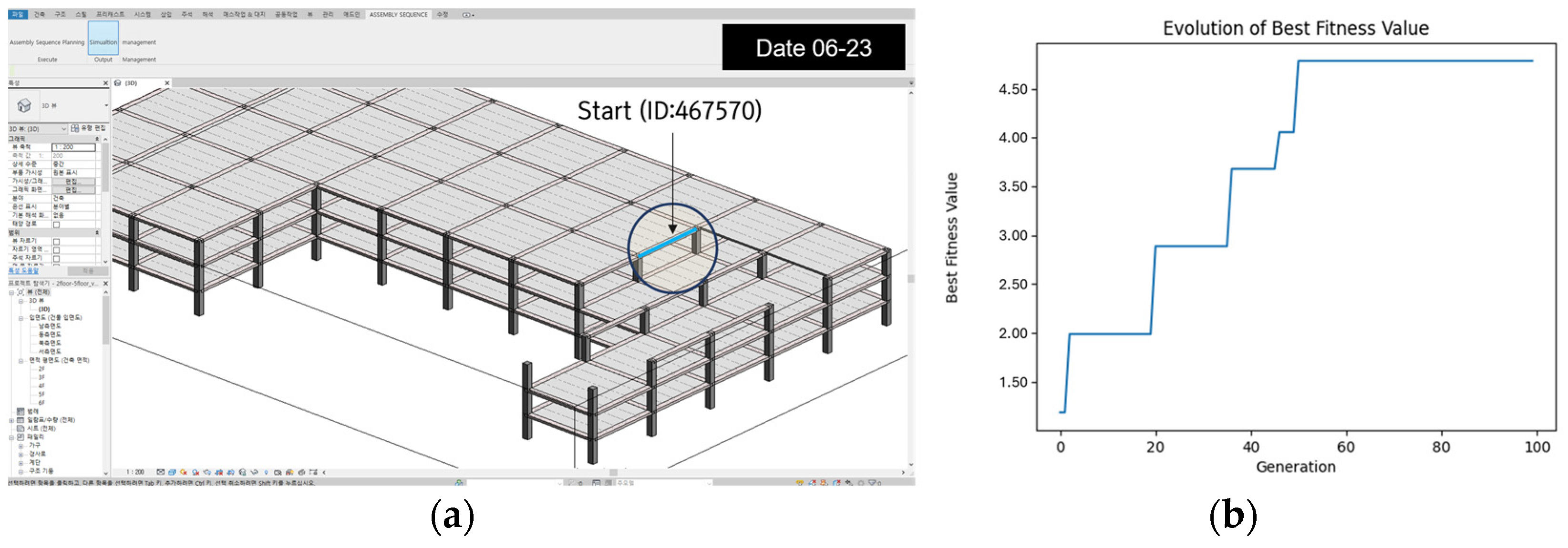
3.2.2. Application of Genetic Algorithm

The crucial encoding process of GAs involves genes (representing PC elements) and chromosomes (representing assembly sequences). Initially, elements marked with an “installation” value of 0 were used as genes for generating assembly sequences. These were combined into an initial chromosome to ensure the unique selection of each ID without overlap. Considering the task complexity, working radius adjacency, and installation feasibility, a penalty score calculation function was developed as the objective function. The roulette-wheel method was employed to select higher-fitness parent chromosomes, paving the way for crossover and mutation processes to generate offspring chromosomes. Figure 6 provides a detailed outline of the crossover and mutation procedures. In crossover, the parent chromosomes are blended at a defined division point to generate offspring, whereas mutations introduce alterations in a single gene within the offspring chromosome.
The implementation of the genetic algorithm involved a meticulous coding process utilizing Visual Studio Code and Python. The initial phase entailed a comprehensive analysis of task intricacies, particularly focusing on consecutive task types and establishing precedent components. The tasks were systematically categorized into distinct entities: columns, beams, and slabs. When consecutive components differ in type, penalty scores are assigned based on the type of the preceding component, as outlined in Section 3.2. In the algorithm, ‘Prev_type’ and ‘current_type’ represent the types of two consecutive components. For example, if a column is followed by a beam, ‘prev_type’ would be a column, and ‘current_type’ would be a beam, resulting in a penalty score of 1 due to the difference in component types. Conversely, when consecutive components are of the same type, such as two consecutive columns, no penalty score is incurred (Algorithm 1).
Algorithm 1 Type penalty
 
# complexity penalty
  for i in range(start_index,n):
     prev_component = result_uninstalled.iloc[individual[i−1]]
     current_component = result_uninstalled.iloc[individual[i]]
 
     prev_type = prev_component['installation time']
     current_type = current_component['installation time']
 
     if prev_type == current_type:
       penalty1 = 0
 
      else:
     if prev_type == 'column':
       penalty1 = 1
     elif prev_type == 'beam':
       penalty1 = 2
     elif prev_type == 'slab':
       penalty1 = 3
 
   penalty_matrix.append(penalties1)
To satisfy the second criterion of adjacency within the working radius, the adjacency penalty score was calculated based on the proximity of the surrounding elements to the reference element. The penalty score was determined by the ratio of the distance values between consecutive elements, and efforts were made to minimize the sum of these penalty scores. This was performed to prioritize the installation of adjacent elements (refer to Algorithm 2).
Algorithm 2 Distance penalty
 
#adjacency penalty
   for i in range(start_index,n):
     prev_component = result_uninstalled.iloc[individual[i−1]]
     current_component = result_uninstalled.iloc[individual[i]]
     diff = np.sqrt((current_component['x coordinate'] - prev_component['x coordinate'])**2 +
           (current_component['y coordinate'] - prev_component['y coordinate'])**2 +
           (current_component['z coordinate'] - prev_component['z coordinate'])**2)
 
     if i > start_index and diff > prev_diff:
       penalty2 = diff/prev_diff
       penalties2.append(penalty2)
     else:
       penalty2 = 0
       penalties2.append(penalty2)
 
     prev_diff = diff
 
     penalties2.append(penalty2)
 
 
   penalty_matrix.append(penalties2)
Regarding the assignment of penalty scores related to the third criterion, assessing the feasibility of the element installation involved considering the schedule and location information within the assembly sequence of each PC element. A penalty score of 1 was assigned when there was a time–space conflict with the initial input schedule of the RC process. To facilitate this, users are required to provide an RC process schedule, including the date and location specifics for each activity (refer to Algorithm 3 for detailed guidance).
Algorithm 3 Interference penalty
 
   #interference penalty
   for i in range(start_index,n):
     prev_component = result_uninstalled.iloc[individual[i−1]]
     current_component = result_uninstalled.iloc[individual[i]]
 
 
     for rc_index in range(len(rc_activities)):
       if (current_member_x == rc_x[rc_index] and
          current_member_y == rc_y[rc_index]) and
          current_member_z == rc_z[rc_index])and
          current_date == rc_date[rc_index]):
         interference_count += 1
 
     penalty3 = interference_count
     print(interference_count)
     penalties3.append(penalty3)
 
   penalty_matrix.append(penalties3)
The assignment of dates to PC elements based on the assembly sequence involved setting a starting date for the sequence generation. The dates were allocated based on the daily capacity of 15 elements. If interference occurred in the RC process schedule based on the user’s input date and location information, a penalty score of 1 was assigned. This process ensures efficient scheduling by preventing time–space conflicts (Algorithm 4).
Algorithm 4 Assigning Data Date
start_date = pd.Timestamp(“23 June 2023)
 
installation_date = start_date + pd.Timedelta(days=installation_date_count // 15)
     if installation_date_count % 15 == 0 and installation_date_count != 0:
       installation_date += pd.Timedelta(days=1)
 
     current_date = installation_date.date()
 
     installation_dates[member_index] = current_date
 
     installation_date_count += 1
Ultimately, the objective is to minimize the cumulative penalty scores from these three constraints, aiming for an assembly sequence with optimal fitness, thereby reducing interference in the construction process (refer to Algorithm 5).
Algorithm 5 Evaluation
def evaluate_fitness(individual):
   penalty = calculate_total_penalty(individual)
   fitness = 1/(penalty)
 
   return fitness,

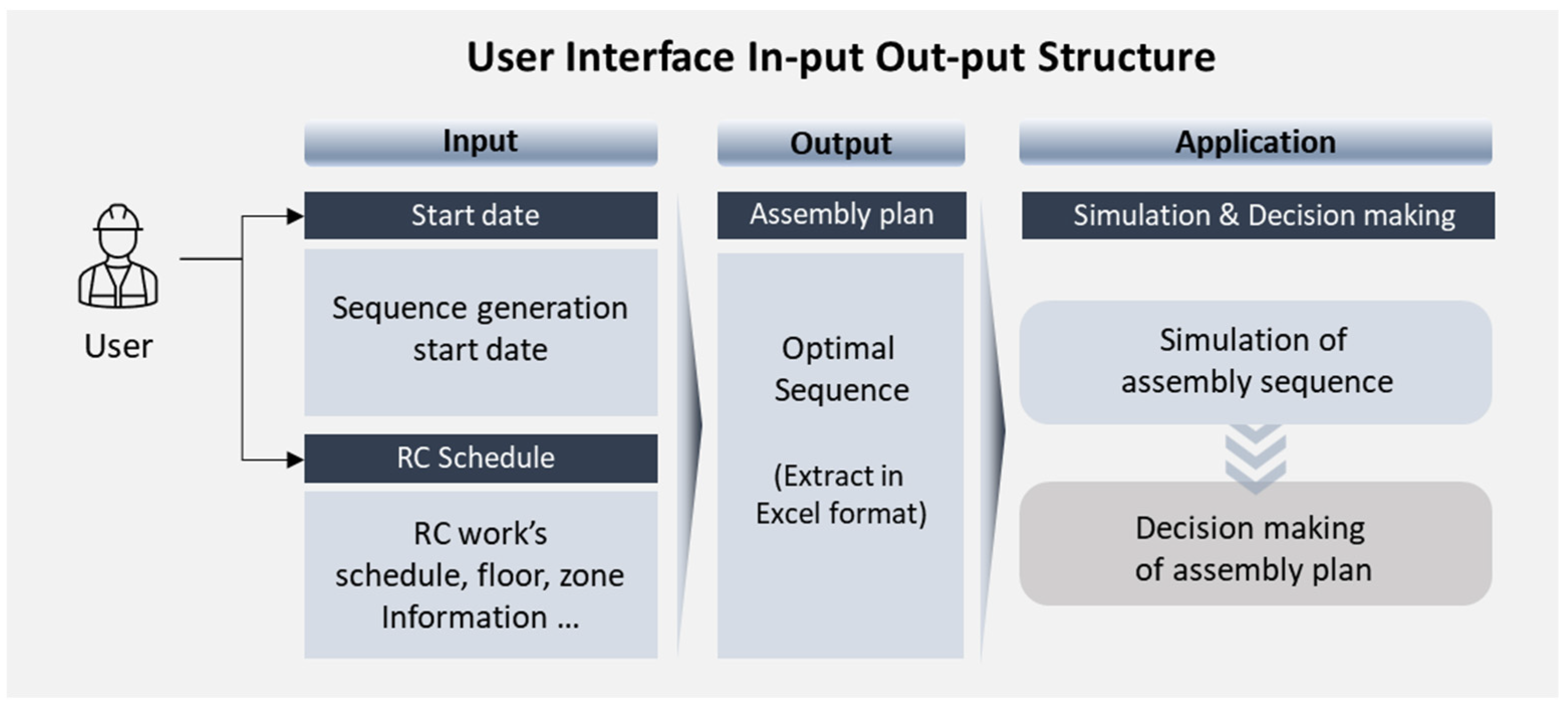
3.2.3. Development of Graphic User Interface (GUI)

A pivotal aspect of implementing the assembly sequence approach is the creation of an intuitive GUI that enables effective data input and result validation. Figure 7 illustrates the system framework, which includes sections for user data input, simulating results based on this input, and managing overall outcomes.
Within this framework (Figure 7), users initiate the process by inputting the preferred commencement date for assembling the PC components along with the RC schedule. The selection of dates can be facilitated by using a calendar interface, visually represented in Figure 8a. The RC schedule, as depicted on the right-hand side of Figure 8b, was integrated. This schedule should encompass specific details of RC activities, including work location, dates, and other relevant details. For example, activities such as topping concrete require details regarding the number of floors, work zones, and scheduled dates. After entering this crucial information, the system generates an optimal assembly sequence based on the concepts outlined in Section 4.
The resulting assembly sequence was stored in an Excel file and simulated using the Revit API. Within the developed Revit API, two critical buttons streamline this process, as shown in Figure 9. First, the assembly sequence planning button organizes the component data according to the generated assembly sequence and conceals them within the model. Secondly, the ‘Simulation’ button enables users to visualize the sequential installation of these concealed components. This installation sequence prioritizes the consecutive placement of similar components aligned with the column beam–slab progression. However, manual intervention may be required if complete structural integrity is not ensured, considering the interconnections between the PC components. Users, relying on the simulation results from button 2, should review the assembly sequence and finalize the plan through manual adjustments if structural stability is not met.

3.3. Phase III: Application and Validation of the Automatic Assembly Sequence Generation System Based on the PC Construction Site

To validate the feasibility of the proposed system, a comprehensive case study was conducted at an actual PC construction site (Figure 10). Table 2 lists the specifics of the chosen site, which served as the primary source for 3D modeling and extracting component details.
The 3D modeling stage was concentrated on a designated space covering floors 2–6 (as depicted in Figure 11), which resulted in 208 columns, 340 beams, and 700 slabs. Each floor accommodated 52 columns, 85 beams, and 175 slabs, all of which were obtained using the procedures detailed in Section 3.2.1. Zoning was uniformly allocated across floors, aligned with the site’s master plan, and is depicted on the right side of Figure 11.
An examination of 208 columns using the extracted data (see Table 3) and the subsequent collection of similar information for beams and slabs were employed in the evaluation conducted using the GA.
When applying the GA to generate assembly sequences, standardization was performed for each constraint to prevent prioritization based on differences in the score scales of task complexity, proximity of work radius, and feasibility of component installation. Subsequently, adaptable weights were applied to these constraints and customized to specific on-site conditions for dynamic prioritization. Through extensive Interview FGIs, it became evident that the most frequent adjustments in assembly plans revolved around component installation feasibility, leading to the assignment of a weight (γ) of 0.5 to this aspect. Acknowledging the substantial impact of work radius adjacency during disruptions or plan alterations, a weight (β) of 0.3 was designated accordingly. Furthermore, task complexity was attributed a weight (α) of 0.2, completing the comprehensive weight assignment process.
Instead of focusing solely on generating initial assembly sequences, we conducted simulations to envision practical scenarios and generated assembly sequences capable of addressing the interference in actual site situations. In the current scenario, the assembly process progresses along the direction of the arrow, as shown in Figure 12a. A situation arose in which some components on the right side of the 4th floor remained uninstalled, starting from 23 June 2023, causing interference with the RC process on 24 June for the highlighted beams and slabs shown in blue in Figure 12b. Examination of the simulation results from these scenarios was aimed at understanding how assembly sequences are generated to effectively address interference.
Through interviews, it was discovered that in situations similar to this case study, a common alternative strategy on PC construction sites involves temporarily postponing sections prone to interference and proceeding with column tasks from the upper-left corner following the work cycle. Using this strategy, the system-generated assembly sequence results were examined. The assembly sequence generation was set for 23 June with a population size of 200 and 100 generations, a crossover probability of 0.2, and a mutation probability of 0.05. The A, B, and C values generated for each of the 200 sequences were normalized to each constraint to prevent varying degrees of constraint dominance across scales. Subsequently, the weights for each constraint were applied, resulting in the determination of the composite penalty score (P) for each assembly sequence. The fitness history count (N) in the table indicates the number of fitness histories calculated for this case study, and P represents the composite penalty score (Table 4).
The analysis identified an assembly sequence that significantly minimized penalties across the three constraints. This specific sequence, commencing with component ID 467570, demonstrates a total penalty value of 0.215, as shown in Figure 13a. A graphical representation of this, shown in Figure 13b, illustrates a converged fitness value of 4.69 for this sequence. The breakdown of penalty scores for this case includes 19 points attributed to task complexity, 34.58 points related to the adjacency of the work radius, and 0 points associated with the feasibility of component installation.
The simulation of this assembly sequence using the Revit API is illustrated in Figure 14, in which the predominant factor shaping the assembly sequence is the feasibility of the components. On the expected date of 24 June, where the interference was foreseen, no components were installed at the designated location. Images 1 and 2 in Figure 14 show a sequence of consecutive beam installations near the initial component. Image 4 in Figure 14 illustrates the process of generating the assembly sequence as of June 24th. In this situation, components strategically avoid installation in the highlighted red areas to prevent interference, prioritizing column installations on the upper levels. Following the procedure outlined in Image 5 of Figure 14, where the adjacency criteria of the work radius are satisfied, nearby column components take precedence in installation. The remaining components were installed at nonconflicting points on subsequent dates, as shown in Figure 6. This outcome demonstrates that by applying the conditions of task complexity, work radius adjacency, and component feasibility, an assembly sequence can be generated to meet the specified constraints. That sequence prioritizes component installation based on feasibility, starting with those in close proximity, while ensuring consecutive installations of the same type of work in nonconflicted situations. As mentioned in Section 3.2.3, users must verify their structural satisfaction after understanding the assembly sequence through simulation. Most assembly sequences have structural stability. Image 3 in Figure 14 shows an instance in which two slabs were installed before all four beams. In such cases, users can actively modify the assembly sequence by adjusting the timing of slab installations to validate and finalize the assembly order.
The analysis of converging results from the graph identified four distinct assembly plan tendencies:
  • Commencing on 23 June, the first strategy involved prioritizing the installation of components in areas expected to face interference, aiming to prevent clashes. However, while emphasizing installation in interference-prone zones without violating the component installation feasibility (Constraint 3), additional penalties for adjacency were incurred.
  • Another strategy commenced by placing the column components in the upper-left corner and postponing the areas susceptible to interference. This sequence aligned with the component installation feasibility but resulted in higher penalties (Constraint 3), primarily because the initial component placement did not meet specific conditions.
  • The third strategy begins with the installation of the upper-left column component, followed by the immediate installation of interference-related components post-overlapping dates. Although this approach prioritizes component feasibility (constraint 3), it incurs penalties for task complexity and adjacency.
  • The fourth approach outlined an assembly plan that deviated from the feasibility of component installation (Constraint 3). In real-world scenarios, construction cannot proceed without timely delivery of PC components. Moreover, in instances where interference with other construction activities occurs, prioritizing PC installations is imperative. Consequently, this assembly plan was excluded because of its impracticality in meeting essential construction requirements.
During the interviews, it was noted that, generally, when on-site situations similar to the one described above occur, the usual practice involves temporarily deferring the conflicting area and proceeding with the initial cycle work on the next floor. However, this study leveraged the developed system to effectively manage on-site conditions, enabling a broader exploration of assembly plan alternatives. Upon comparison with experience-based plans, it was noted that the penalty values for the alternatives did not differ significantly. This suggests the potential for considering a more varied range of on-site plans. Although this study focused on three constraints, future studies could encompass a wider range of constraints, fostering a more systematic and diversified exploration of assembly plans.

4. Validation and Discussion

To validate the practicality and assess the effectiveness of the proposed assembly sequences derived from the defined constraints, thorough interviews were conducted with the site manager who oversaw the PC construction site. Before gathering comprehensive opinions on the developed system, it was confirmed whether the established constraints (task complexity, adjacency of the work radius, and feasibility of component installation) were factors considered at the actual PC construction site during component assembly. Given the characteristics of the PC structure, particularly the öm structure, where columns, beams, and slabs require continuous installation to maintain the structure, it was acknowledged that prioritizing the installation of nearby components in consideration of the workflow is appropriate. It was also noted that adjustments and replanning of assembly sequences are occasionally made by considering the feasibility of component installation.
Subsequently, a comprehensive opinion of the advantages and limitations of the developed system was obtained. Although the system shows promise for systematic on-site management and aligns with digitization trends in the construction industry, further consideration is needed because of the reliance of construction sites on human resources. To ensure seamless adoption, a more diverse array of information should be factored. In addition, the manager highlighted the potential of utilizing the optimal assembly sequence generated by the research results to coordinate with the import schedule, which is a critical aspect of the precast concrete method. However, beyond the constraints addressed in this study, it is essential to incorporate information related to equipment and labor. Furthermore, the manager suggested that the inclusion of a process to verify whether relevant information was appropriately applied and reflected, considering various on-site variables, would enhance the system’s utility in on-site management (Table 5).

5. Conclusions

To address challenges, such as declining productivity in the domestic construction industry, the use of off-site construction methods has become increasingly prevalent. The crucial phase that directly affects the OSC productivity is the on-site assembly process, which is typically subjectively managed. Assembly plans developed based on the subjective experience of on-site managers lack objective validation, making it difficult to determine their true optimality. Moreover, limitations could be identified in swiftly exploring various assembly plans in dynamic construction sites, and the process of considering diverse information and situations at large-scale sites may result in information gaps and errors.
From this standpoint, this study aims to develop a system for generating PC component installation sequences and explore quantitative and objective alternatives for assembly plans to enhance the on-site management efficiency. The goal of this study was to make the system applicable to decision-making regarding assembly plans in real-world scenarios, shifting from subjective reliance on the experience and judgment of on-site managers to a computer algorithmic environment for assembly sequence derivation. To achieve this, factors to be considered during on-site assembly planning and execution such as task complexity, adjacency of the work radius, and feasibility of component installation were objectively evaluated and scored to assess the assembly sequence of the components. A Genetic Algorithm was utilized to generate assembly plan alternatives, minimize constraint violations, and enhance the workflow. The validation process involved in-depth interviews with PC site managers, considering the characteristics of the site that involved additional information related to labor, equipment, and the ability of managers to incorporate changes in on-site conditions. Although suggestions were made for additional functionalities, the basic operational principles and flow of the research results were well reviewed, emphasizing the need for such research in the context of digitizing the construction industry.
This study aims to shift from subjective to systematic on-site management using computer algorithms, thereby contributing to enhanced construction site productivity. Moreover, it identifies direct assembly-phase factors at PC construction sites and seeks to define the assembly-phase mechanism. The study operated under three defined constraints, prioritizing the assembly in the sequence of the column–beam–slab, starting with the closest component. However, it acknowledges a limitation owing to the oversight of component connection relationships, necessitating active user intervention to ensure structural stability. Therefore, future research should include the interconnection relationships among the components to generate more rational assembly plans. This study, in summary, establishes a systematic approach to OSC-based construction assembly sequences, providing a foundation for future research. It is noteworthy that the integration of time–cost analysis into the proposed approach can provide a more comprehensive perspective on both the feasibility and efficiency of a construction practice. In addition, the exploration of the environmental impact and sustainability of assembly sequences responds to the industry’s growing concerns about the sustainability issue in construction.

Author Contributions

Conceptualization, H.C. and S.J.; methodology, S.B.; software, S.B.; validation, S.B. and H.C.; formal analysis, S.B.; investigation, S.B.; resources, H.C.; data curation, S.B.; writing—original draft preparation, S.B.; writing—review and editing, H.C. and S.J.; visualization, S.B.; supervision, H.C.; project administration, S.B.; funding acquisition, H.C. All authors have read and agreed to the published version of the manuscript.

Funding

This research was supported by the Korea Agency for Infrastructure Technology Advancement (KAIA), grant-funded by the Ministry of Land, Infrastructure and Transport (Grant 22ORPS-B158109-03) This work was also supported by the Ajou University research fund.

Institutional Review Board Statement

Not applicable.

Informed Consent Statement

Not applicable.

Data Availability Statement

The data presented in this study are available in article.

Conflicts of Interest

The authors declare no conflicts of interest.

References

  1. Goodier, C.; Gibb, A. Future opportunities for offsite in the UK. Constr. Manag. Econ. 2007, 25, 585–595. [Google Scholar] [CrossRef]
  2. Hwang, B.-G.; Shan, M.; Looi, K.-Y. Knowledge-based decision support system for prefabricated prefinished volumetric construction. Autom. Constr. 2018, 94, 168–178. [Google Scholar] [CrossRef]
  3. Hwang, B.-G.; Shan, M.; Looi, K.-Y. Key constraints and mitigation strategies for prefabricated prefinished volumetric construction. J. Clean. Prod. 2018, 183, 183–193. [Google Scholar] [CrossRef]
  4. Liu, D.; Li, X.; Chen, J.; Jin, R. Real-time optimization of precast concrete component transportation and storage. Adv. Civ. Eng. 2020, 2020, 5714910. [Google Scholar] [CrossRef]
  5. Weber-Lewerenz, B.C. Accents of Added Value in Construction 4.0; Springer Fachmedien: Wiesbaden, Germany, 2022. [Google Scholar] [CrossRef]
  6. Weber-Lewerenz, B.C.; Traverso, M. Innovation Empowerment in Construction 4.0 by the Corporate Digital Responsibility (CDR)—Approach. A New Field of Scientific Research for the Digital Breakthrough. J. Archit. Environ. Struct. Eng. Res. 2023, 6, 41–64. [Google Scholar] [CrossRef]
  7. Wang, Y.; Yuan, Z.; Sun, C. Research on assembly sequence planning and optimization of precast concrete buildings. J. Civ. Eng. Manag. 2018, 24, 106–115. [Google Scholar] [CrossRef]
  8. Arashpour, M.; Wakefield, R.; Lee, E.; Chan, R.; Hosseini, M.R. Analysis of interacting uncertainties in on-site and off-site activities: Implications for hybrid construction. Int. J. Proj. Manag. 2016, 34, 1393–1402. [Google Scholar] [CrossRef]
  9. Liu, C.; Zhang, F.; Zhang, H.; Shi, Z.; Zhu, H. Optimization of assembly sequence of building components based on simulated annealing genetic algorithm. Alex. Eng. J. 2023, 62, 257–268. [Google Scholar] [CrossRef]
  10. Huang, Y.; Shi, Q.; Zuo, J.; Pena-Mora, F.; Chen, J. Research status and challenges of data-driven construction project management in the big data context. Adv. Civ. Eng. 2021, 2021, 6674980. [Google Scholar] [CrossRef]
  11. Agostinelli, S.; Cumo, F.; Marzo, R.; Muzi, F. Digital Construction Strategy for Project Management Optimization in a Building Renovation Site: Machine Learning and Big Data Analysis; Lecture Notes in Civil Engineering; Springer International Publishing: Cham, Switzerland, 2022. [Google Scholar] [CrossRef]
  12. Piras, G.; Agostinelli, S.; Muzi, F. Digital Twin Framework for Built Environment: A Review of Key Enablers. Energies 2024, 17, 436. [Google Scholar] [CrossRef]
  13. Wuni, I.Y.; Shen, G.Q.; Saka, A.B. Computing the severities of critical onsite assembly risk factors for modular integrated construction projects. Eng. Constr. Archit. Manag. 2022, 30, 1864–1882. [Google Scholar] [CrossRef]
  14. Jain, V.; Sethi, P.; Arya, S.; Verma, R.; Chawla, C. Project Evaluation Using Critical Path Method & Project Evaluation Review Technique. Wesley. J. Res. 2020, 13, 1–9. [Google Scholar]
  15. Xie, L.; Chen, Y.; Chang, R. Scheduling optimization of prefabricated construction projects by genetic algorithm. Appl. Sci. 2021, 11, 5531. [Google Scholar] [CrossRef]
  16. Zhu, A.; Dai, T.; Xu, G.; Pauwels, P.; De Vries, B.; Fang, M. Deep Reinforcement Learning for Real-Time Assembly Planning in Robot-Based Prefabricated Construction. IEEE Trans. Autom. Sci. Eng. 2023, 20, 1515–1526. [Google Scholar] [CrossRef]
  17. Faghihi, V.; Reinschmidt, K.F.; Kang, J.H. Construction scheduling using genetic algorithm based on building information model. Expert Syst. Appl. 2014, 41, 7565–7578. [Google Scholar] [CrossRef]
  18. Oltra-Badenes, R.; Guerola-Navarro, V.; Gil-Gómez, J.-A.; Botella-Carrubi, D. Design and Implementation of Teaching–Learning Activities Focused on Improving the Knowledge, the Awareness and the Perception of the Relationship between the SDGs and the Future Profession of University Students. Sustainability 2023, 15, 5324. [Google Scholar] [CrossRef]
  19. Cavallo, M.A.; Ledesma, A.B.; Diaz, L.P.; Facco, S.M.d.L.; Benzi, C.S.; Schmidt Strano, E. Convergencia ODS-universidad. Una propuesta para conocer las expectativas y percepciones de la comunidad académica acerca de la agenda 2030. Inf. Investig. IIATA 2020, 5, 69–81. [Google Scholar] [CrossRef]
  20. Gong, P.; Teng, Y.; Li, X.; Luo, L. Modeling constraints for the on-site assembly process of prefabrication housing production: A social network analysis. Sustainability 2019, 11, 1387. [Google Scholar] [CrossRef]
  21. Ji, Y.; Qi, L.; Liu, Y.; Liu, X.; Li, H.X.; Li, Y. Assessing and prioritising delay factors of prefabricated concrete building projects in China. Appl. Sci. 2018, 8, 2324. [Google Scholar] [CrossRef]
  22. Hong, Y.; Xie, H.; Agapaki, E.; Brilakis, I. Graph-Based Automated Construction Scheduling without the Use of BIM. J. Constr. Eng. Manag. 2023, 149, 05022020. [Google Scholar] [CrossRef]
  23. Liu, H.; Lei, Z.; Li, H.X.; Al-Hussein, M. An automatic scheduling approach: Building information modeling-based onsite scheduling for panelized construction. In Proceedings of the Construction Research Congress 2014: Construction in a Global Network, Atlanta, Georgia, 19–21 May 2014. [Google Scholar] [CrossRef]
  24. Zhou, J.; Love, P.E.D.; Wang, X.; Teo, K.L.; Irani, Z. A review of methods and algorithms for optimizing construction scheduling. J. Oper. Res. Soc. 2013, 64, 1091–1105. [Google Scholar] [CrossRef]
  25. Ng, S.T.; Zhang, Y. Optimizing construction time and cost using ant colony optimization approach. J. Constr. Eng. Manag. 2008, 134, 721–728. [Google Scholar] [CrossRef]
  26. Zhang, H.; Li, H.; Tam, C. Particle swarm optimization for resource-constrained project scheduling. Int. J. Proj. Manag. 2006, 24, 83–92. [Google Scholar] [CrossRef]
  27. Moon, H.; Kim, H.; Kamat, V.R.; Kang, L. BIM-based construction scheduling method using optimization theory for reducing activity overlaps. J. Comput. Civ. Eng. 2015, 29, 04014048. [Google Scholar] [CrossRef]
  28. Nusen, P.; Boonyung, W.; Nusen, S.; Panuwatwanich, K.; Champrasert, P.; Kaewmoracharoen, M. Construction planning and scheduling of a renovation project using BIM-based multi-objective genetic algorithm. Appl. Sci. 2021, 11, 4716. [Google Scholar] [CrossRef]
  29. Anvari, B.; Angeloudis, P.; Ochieng, W. A multi-objective GA-based optimisation for holistic Manufacturing, transportation and Assembly of precast construction. Autom. Constr. 2016, 71, 226–241. [Google Scholar] [CrossRef]
  30. Gonçalves, J.F.; Mendes, J.; Resende, M. A genetic algorithm for the resource constrained multi-project scheduling problem. Eur. J. Oper. Res. 2008, 189, 1171–1190. [Google Scholar] [CrossRef]
  31. Al-Tabtabai, H.; Alex, A.P. Using genetic algorithms to solve optimization problems in construction. Eng. Constr. Archit. Manag. 1999, 6, 121–132. [Google Scholar] [CrossRef]
  32. Essam, N.; Khodeir, L.; Fathy, F. Approaches for BIM-based multi-objective optimization in construction scheduling. Ain Shams Eng. J. 2023, 14, 102114. [Google Scholar] [CrossRef]
  33. Faghihi, V.; Nejat, A.; Reinschmidt, K.F.; Kang, J.H. Automation in construction scheduling: A review of the literature. Int. J. Adv. Manuf. Technol. 2015, 81, 1845–1856. [Google Scholar] [CrossRef]
  34. Huang, L.; Pradhan, R.; Dutta, S.; Cai, Y. BIM4D-based scheduling for assembling and lifting in precast-enabled construction. Autom. Constr. 2022, 133, 103999. [Google Scholar] [CrossRef]
  35. Shehata, M.E.; El-Gohary, K.M. Towards improving construction labor productivity and projects’ performance. Alex. Eng. J. 2011, 50, 321–330. [Google Scholar] [CrossRef]
  36. Kang, L.S.; Park, I.C.; Lee, B.H. Optimal schedule planning for multiple, repetitive construction process. J. Constr. Eng. Manag. 2001, 127, 382–390. [Google Scholar] [CrossRef]
  37. Vaux, J.S.; Kirk, W.M. Relationship conflict in construction management: Performance and productivity problem. J. Constr. Eng. Management 2018, 144, 04018032. [Google Scholar] [CrossRef]
  38. Moon, H.; Dawood, N.; Kang, L. Development of workspace conflict visualization system using 4D object of work schedule. Adv. Eng. Inform. 2014, 28, 50–65. [Google Scholar] [CrossRef]
  39. Kim, S.I.; Noh, Y.; Kang, Y.J.; Park, S.; Ahn, B. Fault classification model based on time domain feature extraction of vibration data. J. Comput. Struct. Eng. Inst. Korea 2021, 34, 25–33. [Google Scholar] [CrossRef]
Figure 1. Research methodology. (Source: own elaboration).
Applsci 14 01358 g001
Figure 2. System framework. (Source: own elaboration).
Applsci 14 01358 g002
Figure 3. Process of generating optimal assembly sequence. (Source: own elaboration).
Applsci 14 01358 g003
Figure 4. 3D modeling and extracting centroid of PC components. (a) Comprehensive BIM model. (b) Highlighted centroids for each component. (Source: own elaboration).
Applsci 14 01358 g004
Figure 5. Extracting information of PC components. (Source: own elaboration).
Applsci 14 01358 g005
Figure 6. Cross-over and mutation of assembly sequence. (Source: own elaboration).
Applsci 14 01358 g006
Figure 7. User interface input–output structure. (Source: own elaboration).
Applsci 14 01358 g007
Figure 8. GUI of information input part. (a) Calendar interface. (b) RC schedule file. (Source: own elaboration).
Applsci 14 01358 g008
Figure 9. Development of Revit API. (Source: own elaboration).
Applsci 14 01358 g009
Figure 10. Case study project. (Source: k construction company).
Applsci 14 01358 g010
Figure 11. Integrated BIM representation of the construction site. (a) Floor Plan. (b) Elevation. (c) Zone information. (Source: own elaboration).
Applsci 14 01358 g011
Figure 12. Current status information. (a) Current situation. (b) Components with interference. (Source: own elaboration).
Applsci 14 01358 g012
Figure 13. Result of the case study. (a) Starting component ID and location. (b) Converged fitness value. (Source: own elaboration).
Applsci 14 01358 g013
Figure 14. Simulation of the result using Revit API. (Source: own elaboration).
Applsci 14 01358 g014
Table 1. Example of PC component information. (Source: own elaboration).
No.IDxyzLevelZoneInstallation
0442407−43,609−112,33338003A1
1442452−32,609−112,33338003B1
2442559−21,609−112,33338003A0
3442636−10,609−112,33338003B0
4442687390−112,33338003A0
Table 2. Overview of the construction site. (Source: own elaboration).
Project NameP knowledge Industry Center
Period2022~2024
StructurePrecast concrete
PurposeKnowledge industry center
Site area 7414   m 2
Building area 5170   m 2
Floor area 48 , 535   m 2
No. of FloorsB1~10F
Table 3. Information of PC column. (Source: own elaboration).
No.IDxyzLevelZoneInstallation
0442407−43,609−112,23338002A1
1442452−32,609−112,23338002A1
2442559−390−112,23338002A1
206471581390−161,85315,8505B0
20747189644,390−150,83315,8505B0
20847194121,609−150,83315,8505B0
Table 4. Result of the simulation. (Source: own elaboration).
No.Assembly Sequence (Component ID)Penalty Score
1467570, 467680, 468432, 467598, 470266, 467678, 468567, 470268, 470279, 468477, 469197, 470288, 470297, …0.215
2467650, 467670, 467676, 469242, 468522, 470278, 467572, 467652, 467648, 467570, 467554, 467598, 467668, 470257,…0.229
3470297, 469242, 469197, 467678, 470278, 470265, 470268, 470264, 470259, 467572, 467570, …0.284
4470279, 470269, 470257, 470266, 470276, 467648, 470265, 467590, 467606, 470297, 467650, …0.409
5467676, 470278, 470287, 467678, 467648, 467570, 468567, 470279, 470288, 470259, 470297, 467552, …0.232
6469242, 467668, 468477, 470269, 467598, 470277, 470266, 470303, 467590, 470265, 470268, 470257, …0.573
7467598, 467646, 467570, 467590, 467674, 467668, 467676, 470276, 470264, 467652, 470297, …0.308
18470257, 467674, 467552, 467676, 467606, 470276, 470266, 470259, 468477, 467680, 467648, …0.349
19470266, 470279, 470269, 470259, 470287, 470257, 467606, 467676, 468522, 470276, 467588, 467650, …0.487
20470258, 470276, 467646, 467570, 467588, 467676, 470297, 467670, 470303, 467678, 467606, …0.490
NNth Assembly sequenceP
Table 5. Evaluation of research. (Source: own elaboration).
TypeNo.Evaluation
Advantage1In digitized construction sites, such management approaches are essential, and they are expected to aid in systematic on-site management.
2When undertaking construction projects with PC structures in urban or similar areas, the scarcity of space for PC component storage necessitates a thorough assembly and delivery plan. Considering this, the study is anticipated to contribute by identifying the optimal assembly sequence to address these challenges.
3A system that verifies the anticipated assembly sequence through simulation proves highly beneficial for on-site management.
Limitation1Consideration of additional variables occurring on site is essential. Developing an assembly plan that comprehensively integrates factors such as weather, manpower, and equipment would contribute to a more systematic assembly plan.
2As construction sites continue to heavily depend on manpower, a successful application of this methodology requires a comprehensive management system, encompassing not only the construction phase but also information from all preceding stages, including transportation and delivery, to enhance feasibility.
Disclaimer/Publisher’s Note: The statements, opinions and data contained in all publications are solely those of the individual author(s) and contributor(s) and not of MDPI and/or the editor(s). MDPI and/or the editor(s) disclaim responsibility for any injury to people or property resulting from any ideas, methods, instructions or products referred to in the content.

