Article

LR-MPIBS: A LoRa-Based Maritime Position-Indicating Beacon System

College of Ocean Science and Engineering, Shandong University of Science and Technology, Qingdao 266590, China
*
Author to whom correspondence should be addressed.
Appl. Sci. 2024, 14(3), 1231; https://doi.org/10.3390/app14031231
Submission received: 30 December 2023 / Revised: 28 January 2024 / Accepted: 31 January 2024 / Published: 1 February 2024
(This article belongs to the Special Issue Advances in Internet of Things and Computer Vision)

Abstract

:
Human marine activities are becoming increasingly frequent. The adverse marine environment has led to an increase in man overboard incidents, resulting in significant losses of life and property. After a drowning accident, the accurate location information of the drowning victim can help improve the success rate of rescue. In this paper, we explore a LoRa-based Maritime Position-Indicating Beacon System (LR-MPIBS). A low-power drowning detection circuit is designed in LR-MPIBS to detect drowning accidents in a timely manner after a person falls into the water. The instantaneous high current of the LoRa RF can lower the supply voltage and cause other modules to work abnormally. A fast current transient response circuit is proposed to solve the problem. LR-MPIBS includes a power ripple suppression circuit that can reduce the measurement errors and operational abnormalities caused by power ripple interference. We explore the impedance matching law of LoRa RF circuits through simulation experiments to improve the quality of LoRa communication. A data processing algorithm for personnel drift trajectory is proposed to alleviate the challenges caused by the raw positioning data with large deviations and high communication cost. The experimental results show that LR-MPIBS can automatically start and actively alarm within 3 s after a person falls into the water. The positioning cold start time is less than 50 s. The performance of communication distance is more than 5 km. The endurance of LR-MPIBS is 25 h (with a 30 s communication cycle).

1. Introduction

The ocean plays an important role in national strategy and is an integral component of economic development. Human activities on the ocean have also increased year by year. The harsh marine environment increases the risk of man overboard, which poses a serious threat to life, property, and the safety of offshore operators. The maritime incidents of man overboard have the characteristics of suddenness, urgency, concealment, and short warning time. These factors collectively lead to many challenges in rescuing drowning personnel in distress [1]. The timely acquisition of accurate location information of drowning personnel by rescue teams can improve the efficiency of emergency rescue. In response to this, researchers have developed the Position Indication Beacon System (PIBS) and achieved some results in two main areas: radio measurement [2] and satellite navigation [3].
Wang designed a drowning alarm system, which includes two parts: the base station and the user terminal. The base station employs a time division multiplexing method to poll each user terminal every 5 s, and evaluate personnel drowning events based on the response information from the user terminals or a lack of response [4]. This can detect incidents of personnel falling into the water, but a high false alarm rate is reflected in situations of communication interference or terminal shutdown. Zhao designed a beacon system that integrates On-Off Keying (OOK) technology and interferometer orientation technology [5], with a performance of orientation measurement accuracy within 10 degrees. Interferometer orientation technology was also used by the Royal Navy of the United Kingdom to design the Sea Marshall personnel search and positioning system. The developments based on wireless directional measurement technology have the problem of low measurement accuracy [6,7], as wireless transmission at sea is subject to interference.
With the vigorous development of satellite navigation technology, researchers integrate satellite navigation technology into the research of PIBS [8,9,10,11]. Huang designed a lifesaving terminal based on BeiDou positioning and BeiDou short message technology [12]. During emergency rescue, terminal equipment sends distress messages to nearby ships and coastal bases at regular intervals (1 min to 30 min). This utilizes Beidou short message technology to solve the problem of limited distance in commonly used communication methods, but due to the directional constraints of Beidou antenna communication, the communication success rate is relatively low. Zhao designed personal and maritime AIS-EPIRB, which combines AIS technology with satellite navigation technology [13]. This system can send the location information of a drowning person to ships or shore-based facilities equipped with AIS systems within a range of 5 nautical miles. The AIS system has not achieved full coverage of ships at sea, which limits the convenient deployment of the beacon system [14,15,16]. Hu designed an automatic alarm system for falling into the sea, which integrates ShockBurst technology and BeiDou navigation technology [17], and provides a falling detection scheme. The system detects man overboard accidents by fusing data from three sensors: an acceleration sensor, a pressure sensor, and a humidity sensor. This method improves the accuracy of accident detection, but sacrifices the operational lifespan of the system. The beacon system designed with satellite navigation technology achieves a positioning accuracy better than 10 m. Nevertheless, the convenience of beacon system deployment and the endurance of the system still have substantial room for improvement.
In this paper, we design a LoRa-based Maritime Position-Indicating Beacon System (LR-MPIBS), which integrates LoRa technology [18,19,20] and BeiDou satellite navigation technology to address the challenges faced by existing PIBS in terms of endurance, false alarm rate, and deployment convenience. The LR-MPIBS helps to further maintain the safety of ship navigation, especially for ships with difficulties in searching and rescuing personnel who have fallen into the sea.

2. Materials and Methods

2.1. Overall System Design

2.1.1. Function Analysis

Rapid alarm and positioning are the keys to efficient rescue, especially in the emergency rescue process of personnel falling into the water. Considering actual rescue scenarios and methods, the LR-MPIBS should meet the following requirements:
(1)
The automatic detection function of man overboard is an important guarantee for improving the alarm rate in such emergency situations. The height from the ship deck to the sea surface is generally greater than 3 m, and the drowning person may lose consciousness or go into shock, making it difficult to manually operate the alarm. It is necessary to implement the automatic detection of such incidents. This will improve the timeliness of the alarm.
(2)
Accurately locating people overboard is the basis of efficient marine rescue. Rescue teams can use accurate location information to make reasonable rescue decisions [21]. The LR-MPIBS is required to provide accurate global positioning information for a person in distress overboard.
(3)
The timely acquisition of rescue information is the core of man overboard rescue. Rescue teams need to obtain position information and identify people in distress as early as possible. LR-MPIBS can utilize long-distance wireless communication to reliably and securely transmit location information to rescue teams.
(4)
The important function of the beacon system is to display the operating status of the equipment in a prominent and clear manner. Drowning people are prone to negative emotions such as fear, anxiety, and despair. They use the visual indicators to check the system status and external rescue information, which helps to stabilize their emotions.

2.1.2. System Architectural Design

Based on the above analysis, the core functions of the position-indicating beacon system should include personnel drowning detection, automatic alarm, global positioning, wireless communication, and indicator lights. The LR-MPIBS consists of a ship-mounted base station (SMBS) and position-indicating terminal (PIT). The application scenario and workflow are shown in Figure 1. SMBS is installed on the rescue ship, with the antenna located on a relatively open and high place on the ship. Each crew member is equipped with a PIT. When the crew falls into the sea, the PIT can automatically detect and power on. During the rescue process, the PIT regularly collects BeiDou positioning information and transmits it to the SMBS through LoRa communication. The rescue ship can obtain information about the drowning person and carry out rescue operations.
The overall architecture of the LR-MPIBS developed in this paper is shown in Figure 2. It includes three layers: a system-hardware layer, a communication-protocol layer, and a data-processing layer.
(1)
System-Hardware Layer: This is the hardware foundation of LR-MPIBS. The system-hardware layer is divided into PIT and SMBS parts. The main control module of the PIT implements data acquisition, wireless communication, light indication, and other control functions. The Falling Water Detection (FWD) module monitors the situation of personnel falling into the water in real time, and automatically turns on the PIT after the crew falls into the water. The Beidou positioning module is used to realize the precise positioning of the drowning person. The wireless communication module uses LoRa technology to transmit data between the PIT and the SMBS under the harsh marine environment. The button and indicator module are used for switching the operation mode of the PIT and displaying the operation and rescue status to personnel in distress. The power-management module is responsible for voltage conversion and supplying power to the equipment. The master control module, wireless communication module, and power-management module of the SMBS have similar functions as their counterparts in the PIT. The computer communication module of the SMBS forwards valid rescue information from the PIT to the rescue team.
(2)
Communication Protocol Layer: This defines the communication protocol format of each module within the LR-MPIBS to ensure safe and accurate data transmission. The Beidou communication protocol of the PIT allows the positioning module to transmit NMEA-0813 messages to the main control module. The LoRa wireless communication protocol includes the rescue information protocol of PIT and the response information protocol of SMBS. The rescue information protocol is used to encapsulate basic rescue information such as personnel identifiers and locations, while the response information protocol is used to encapsulate communication responses and base station numbers. The SMBS drowning rescue data transmission protocol forwards distress rescue information to rescue teams.
(3)
Data-Processing Layer: It processes positioning and rescue data to ensure the validity and reliability of communication data. The verification of the validity of positioning data is used to filter data with large deviations. The extracting of key positioning data is used to extract key turning points in the trajectory of individuals drifting at sea. The compression of positioning data is used to compress key positioning data in wireless communication cycles and reduce communication traffic. The verification of SMBS rescue information is used to verify the integrity of rescue information.

2.2. Design and Implementation of System Hardware

2.2.1. Main Control Module

The main control module needs to process and transmit data from various functional modules, and needs to have high performance. The STM32F1 series microcontroller (designed by Italian semiconductor) is used as the control core in this design. Its main frequency is 72 MHz, and the current in standby mode is microampere. The main control module of the SMBS employs the same microcontroller.

2.2.2. Falling-Water-Detection (FWD) Module of the Position-Indicating Terminal

The FWD module uses the conductive properties of seawater to detect drowning persons. The charging interface pins and FWD detection pins are exposed outside the PIT protective casing and come into contact with seawater. If the positive pole of the power supply is selected as the detection pin, it can form a cascaded circuit with the charging interface and generate interference current when a person falls into the water. Meanwhile, the power supply voltage fluctuates due to electromagnetic interference from seawater. The negative pole of the power supply is used as a detect pin instead of the positive pole, which can avoid the issues mentioned above. According to Kirchhoff’s Voltage Law, seawater is a conductive medium that participates in the circuit’s voltage division, resulting in an increased reference voltage in the detection circuit. Additionally, this voltage varies with different marine areas. The PIT trigger’s automatic startup needs the voltage to drop below 0.85 V for more than 3 s. Therefore, randomness exists in using the negative pole as the detect pin for automatic startup in the FWD module. The FWD circuit shown in Figure 3 is designed to solve this randomness problem. After personnel fall into the water, the output voltage of U1 is controlled to a low level, and PIT triggers an automatic start. At the moment of startup completion, the output voltage of U1 is constantly controlled at a high level to ensure the stable operation of PIT.
The emitter terminal (FWDP1) of transistor Q1 and the negative pole of power supply are selected as the trigger pins of FWD. During the immersion detection process, FWDP1 and GND will conduct and control Q1 to a saturation state [22]. The Q1 collector reference voltage exhibits instability due to changes in sea salinity values, meaning it cannot be directly used as a trigger pin. The voltage comparator (U1) is connected to the Q1 post stage to ensure that the output voltage of the control U1 (TAS) is always below 0.85 V in the Q1 saturation state.
The switch transistor Q3 is added to the front stage of Q1 to prevent the frequent triggering of the automatic startup signal caused by personnel floating on the sea surface. After the start of PIT, Q3 enters a saturation state and controls Q1 to a cutoff state to ensure that the output voltage of U1 remains constant at a high level during the running of PIT.
Equation (1) is used to calculate the circuit running current:
I R = 3.3 U b e 3 R 20 + V B A T U c e 3 R 12 + R 25 + 10
Ube3 is the Q3 base–emitter conduction voltage drop, which has a value of 0.65 V. Uce3 is the Q3 collector–emitter saturation voltage drop, which has a value of 0.6 V. The resistance values of R25, R20, and R12 are in the range of 30–60 kΩ, and the operating current of U1 is 10 µA. The operating current of the FWD (IR) is 90 µA. In the PIT shutdown state, the current consumption of FWD is the cut-off current Icbo of Q3 and the operating current of U1, with a value of 10.1 µA.

2.2.3. Wireless Communication Module

Wireless communication on the sea surface is affected by complex marine electromagnetic noise interference, resulting in the attenuation and distortion of radio frequency signals during transmission [23,24]. LoRa technology adopts a unique Chirp modulation scheme and spread spectrum communication technology, which establishes the advantages of strong anti-interference ability, high network capacity, and flexible deployment in LoRa communication. The LoRa chip also has low power consumption and an LBT (Listen Before Talk) mechanism [25], which helps in the low-power and stable communication design of LB-PIBS. In this paper, we select SX1268 as the communication chip of LR-MPIBS, and set its transmission power to 22 dBm and communication frequency to 433 MHz.
LoRa RF signals suffer from transmission and reflection losses during hardware circuit transmission. The reflected signal is prone to mixing with the original signal, resulting in signal distortion. The reasonable design of RF transmission-line impedance can reduce transmission loss [26,27]. The transmission-line impedance-matching value is simulated through SI9000. Its relationship with the communication performance is shown in Table 1. When the transmission line width is 6.5 mil, the simulated impedance value is 66.91 Ω and the communication distance is just 28 m. With increasing line width, the impedance value decreases, and the communication distance is greatly improved. The communication performance is optimal when the RF transmission line width is adjusted to 21.71 mils, with an impedance value of 50 Ω. Its communication success rate can reach 95% within a distance of 3.5 km in open areas.
Antenna selection is another key problem in the design of the wireless communication module. The performance of the antenna directly affects the signal gain, directionality, anti-jamming, and stability of the working band [28]. We promote the screening research of the antennas for the PIT and the SMBS. A large suction cup, an omnidirectional copper pillar antenna with a gain of 8 dBi, was installed as the communication antenna for SMBT in the open area at a high altitude on the ship. The antenna selection for the PIT took into account the small size of the equipment, waterproof sealing, and electromagnetic interference. A built-in PCB patch antenna with a gain of 5 dBi was chosen.

2.2.4. Power-Management Module of the Position-Indicating Terminal

The design of the power-management module of the PIT focused on the power-supply and voltage-regulator circuit. The PIT integrates Beidou positioning and LoRa RF circuits. The power management module should have good ripple suppression capability to reduce the impact of power-supply-ripple interference on the stability and reliability of RF communication. The stable working current of PIT is about 50 mA, and the transient peak current of communication will reach 156 mA. A high transient current can cause a decrease in power supply voltage and lead to PIT shutdown. Therefore, we design a highly reliable power supply circuit to improve the source ripple suppression and transient response capability of the power supply.
The selection of power supply batteries in this paper focuses on their transient response capability, output voltage, and battery capacity. Its transient peak output current should exceed three times the transient operating current of PIT. Its output voltage range is between 3.6 V and 4.2 V, meeting the working voltage requirement of 3.3 V for each module. A lithium battery has a higher energy density and longer lifespan compared to other types of battery, so we prefer lithium batteries. The voltage of a typical small lithium battery is 3.7 V, and the discharge rate (C) is 1. We can calculate based, on Formula (2), that the battery capacity needs to be greater than 486 mA, taking into account the transient response requirements of the battery.
I = M × C n
The power supply battery used in this paper is a 3.7 V lithium battery with a capacity of 1500 mAh and a discharge rate of 1C. This means that the maximum transient current the power supply can deliver is 1500 mA.
The power-management circuit is shown in Figure 4. This circuit is used to regulate the power-supply voltage to the 3.3 V required for each functional module. The electrolytic capacitor CT112 in the ripple-filter circuit is used to absorb instantaneous current transients caused by power-supply voltage fluctuations during RF communication. The range of its capacitance value is 10–100 μF. Ceramic capacitors C114 and C116 are used for the main ripple filter capacitance: C114 is a low-frequency filter with a value range of 1.0–4.7 μF. C116 is a high-frequency filter with a value range of 10–100 nF. The TLV757P-3.3 regulator chip (U5) from Texas Instruments is used to regulate voltage. It has a maximum transient load capacity of 1 A. The 1 μF ceramic capacitor C115 is used to ensure that the output voltage ripple is below 45 mV.

2.3. Workflow and Data-Processing Algorithm

2.3.1. Workflow of the LR-MPIBS System

The basic workflow of the LR-MPIBS is shown in Figure 5. PIT starts and initializes each functional modules when it detects someone falling into the water or long pressing the power button for 3 s. The microcontroller receives the NMEA-0813 message sent by the Beidou module, and then analyzes and processes the positioning data in it. The LoRa communication module sends rescue information packets encapsulated according to the rescue information protocol, which contain information such as personnel numbers and positioning data. When SMBS receives rescue data packets, it verifies and analyzes them. After successful verification, SMBS sends a response packet to PIT and forwards the rescue information to the backend server. This is a complete process for the reliable transmission of rescue information. LR-MPIBS operates in a loop according to the above process until PIT stops sending.

2.3.2. The Positioning Data Processing Algorithm of PIT

The positioning data received by the PIT Beidou module at a frequency of 1 Hz may have large deviations or errors due to interference from the sea-surface environment [29]. The existing position indicator system only sends the latest positioning point information within the alarm message transmission cycle (>30 s), and the available positioning data in the background are limited. This transmission method affects the accurate judgment of the position of the drowning personnel and the prediction of drift trajectories, reducing rescue efficiency. In this paper, we design a positioning data processing algorithm for the PIT. During the receiving cycle, the algorithm evaluates the validity of each positioning datum in real time, extracts key point coordinates, and caches them to an array ( a r r a y K P D ). Finally, the key point dataset is compressed and encapsulated into packets for transmission. This algorithm increases the accuracy and quantity of positioning data obtained in the background while ensuring energy consumption, effectively improving rescue efficiency.
(1)
Verify The Positioning Data Validity: A maximum distance estimation model for drowning drift is designed to test the effectiveness of the positioning data obtained during the receiving cycle, discarding large deviation data. The maximum drift distance ( t h r e _ e r r ) estimation formula is
t h r e _ e r r = k e r r × v m a x × Δ t + 2 × l o c a e r r
where k e r r is the estimation coefficient, v m a x 1.0 ,   2.5   m / s is the maximum value of sea-surface horizontal drift velocity [30], Δt is the time interval from the latest historical valid positioning data acquisition time to current, and l o c a e r r is the maximum random measurement deviation of the Beidou module. d i s _ p p represents the distance difference between the current collected positioning data and the latest historical valid positioning data. The d i s _ p p can be calculated using Formula (4) as follows:
d i s _ p p = R × arccos ( cos ( w p l a s × π 180 ) × cos ( w p p r e × π 180 ) × cos ( j p l a s × π 180 j p p r e × π 180 ) + sin ( w p l a s × π 180 ) × sin ( w p p r e × π 180 ) )
where R = 6371 km is the radius of the earth, and j p l a s , w p l a s , j p p r e , and w p p r e , respectively, denote the longitude and latitude of the current and previous positioning data.
The d i s _ p p and t h r e _ e r r are obtained using Formulas (3) and (4). If d i s _ p p is less than t h r e _ e r r , the previously retained valid positioning data will be saved to P p r e and the current positioning data will be retained to P l a s u for subsequent key data extraction. Otherwise, the current positioning data will be discarded. This operation improves the effectiveness and accuracy of the positioning data to be sent.
(2)
Extract The Key Positioning Data: The positioning data collection frequency of LR-MPIBS is 1 Hz, and the minimum alarm transmission cycle is 30 s. If all valid data within the cycle are encapsulated and sent, there is a large amount of redundant information in the rescue information packet. Long data packets can lead to increased energy consumption and may reduce the success rate of data transmission [31]. We design a Key Positioning Data Extraction Algorithm (KPDEA) for the drift trajectory of personnel on the sea surface, which extracts key positioning data and stores it in the arrayKPD. These data are used for subsequent compression and encapsulation.
The drift trajectory can be divided into three categories: relatively static, wide-angle turning, and small-angle turning. These features are used in the design of KPDEA.
First, the position of the person may have a small range of movement or they may be static, the drift distance is within a certain range. The following can thus be used to identify movement over a small range in the positioning data:
t h r e _ m i n = k min × v min + 2 × l o c a e r r
where k m i n is the model estimation coefficient and v m i n 0.0 0.5 m / s is the minimum value of the sea-surface horizontal drift velocity. If d i s _ p p is less than t h r e _ m i n , this indicates that the personnel drift range is small, and the previously stored key point information can be used to replace the current location information, discarding the current location information. Otherwise, we use the subsequent feature recognition methods.
Secondly, we extract a key positioning point for the drift trajectory of drowning personnel through a wide-angle turning feature. We establish tow vectors of the latest drift trajectory direction vector P p r e P l a s u and the last historical drift trajectory direction vector P o r i P d i r of the personnel. The key positioning points P o r i and P d i r denote the starting and ending coordinates of the last historical drift trajectory direction vector, respectively. The valid positioning data P p r e and P l a s u denote the starting and ending coordinates of the latest drift trajectory direction vector, respectively. The trajectory pinch-angle θ l a s is calculated between this two vectors. The algorithm extracts key positioning points by comparing θ l a s with the angle threshold θ t h r e set by the system. The method for extracting key positioning data from wide angles feature is as follows:
The original positioning data obtained by Beidou are mapped onto the WGS-84 coordinate system, which causes the setting of θ t h r e to vary according to different geographic locations. In this paper, the θ t h r e setting is simplified by projecting the trajectory vector into an xy coordinate system. Taking the vector P p r e P l a s u as an example, the latitude and longitude coordinates of P l a s u are projected to the xy coordinate system with P p r e as the origin, using
x l a s u = 111 × cos ( w P p r e × π 180 ) × ( j P l a s u j P p r e ) × 1000 y l a s u = 111 × ( w P l a s u w P p r e ) × 1000
where x l a s u   and y l a s u denote the actual offset distance (m) of P l a s u relative to P p r e in the longitude and latitude directions, respectively. The coordinate representation of vector P p r e P l a s u is ( x l a s u , y l a s u ) .
The trajectory pinch-angle calculation formula is
θ l a s = P p r e P l a s u , P o r i P d i r = arccos ( x l a s u × x d i r + y l a s u × y d i r x l a s u 2 + y l a s u 2 × x d i r 2 + y d i r 2 )
where x d i r   and y d i r denote the actual offset distance (m) of P d i r relative to P o r i in the longitude and latitude directions, respectively. If θ l a s is larger than θ t h r e , this indicates the occurrence of a wide-angle turning feature. P p r e are the key positioning data, which are stored in the a r r a y K P D of key positioning data. Otherwise, one must further extract key positioning data through the small-angle turning feature.
Third, we extract key positioning data for the drift trajectory of drowning personnel through a small-angle turning feature. The vertical distance d l a s from P l a s u to the historical drift trajectory is calculated in the X-Y coordinate system. The algorithm extracts key positioning data by comparing d l a s with the distance threshold d t h r e set by the system. The method for extracting key positioning data from small angles is as follows:
In the x-y coordinate system centered on P o r i , the expression for the latest historical drift trajectory is
f ( x t r a ) = ( y d i r x d i r ) x t r a
The shortest actual offset distance from P l a s u to f ( x t r a ) in this coordinate system is expressed as
d l a s = k x P l a s u y P l a s u 1 + k 2
where k is the slope of f ( x t r a ) , and x P l a s u and y P l a s u denote the actual offset distance of P l a s u relative to P o r i in the longitude and latitude directions, respectively. If d l a s is larger than d t h r e , this indicates the occurrence of small-angle turning features. P p r e are the key positioning data, which are stored in the a r r a y K P D of key positioning data. Otherwise, they will be discarded.
(3)
Compress The Key Positioning Data: arrayKPD contains multiple key positioning data, which are calculated and stored using floating-point data types. This article focuses on the continuous features of key positioning data in spatial distribution and designs an improved differential encoding method to reduce the space occupied by key positioning data. The compression method is as shown in Formula (10).
j p i w p i = j p i + 1 w p i + 1 j p i w p i × 10 7
where j p i and w p i represent the latitude and longitude of the ith key positioning data stored in the current cycle, while Δ j p i and Δ w p i represent the latitude and longitude increment information of the ith key positioning data, and i increases by 1 in each cycle.
At the time of communication cycle arrival, the main control unit sequentially calculates the adjacent increment of key positioning data in longitude and latitude, and converts the increment information into the short data type for storage. It is worth noting that the incremental information of the latest key positioning data is obtained through calculating of the latest effective positioning data and the latest key positioning data. This encoding method can compress 50% of the storage space of key positioning data while ensuring the accuracy of positioning data.

2.3.3. Design of Wireless Communication Protocol

(1)
Rescue Information Protocol for PIT: The frame format of the rescue information protocol of the PIT is shown in Table 2. This includes the header, message length, message body, check digit, and tail. The header and the tail are 0xEF and 0xFE, respectively. These are used to separate and identify the information. The message length helps the message content to be correctly parsed. The message body is the main object of transmission, and it includes the information required for emergency rescue. The CRC16 algorithm is employed for the check digit, which is used to detect whether the information has been tampered with, and the algorithm’s polynomials are
g ( x ) = x 15 + x 12 + x 5 + 1
Table 2. Rescue information packet structure.
Message HeadMessage LengthMessage BodyCheck DigitMessage Tail
0xEF4 × i + 25Basic rescue informationContent validation0xFE
The content of the message body is shown in Table 3. This includes number information, the current latest valid positioning data, latitude/longitude increment information of key positioning data, and functional information. The numbering information includes the base-station number and personnel number, which are each composed of eight characters and are used to associate the marine operators and rescue vessels. The current latest valid positioning data are the data stored at the time of the alarm of the PIT. These are stored as float type data. The key positioning information comprises the key data points within the drift trajectory of the person in distress during the corresponding cycle, and it is stored as short type data. The key positioning functional information is used to transmit the battery information of the PIT, and its value is 0x23 when the voltage is lower than 3.45 V, which warns the rescue team to give priority to rescue.
(2)
Response Information Protocol for SMBS: The content of the SMBS response information is shown in Table 4. This includes ID information and function information. The ID information contains the base-station ID and personnel ID, which each consist of eight characters. The function information is used to convey the current status of the rescue team to the person in distress; a value of 0x11 indicates that the rescue operation has started and the indicator light of the PIT will be switched to white to pacify the person in distress.

3. Results and Discussion

The physical configuration of LR-MPIBS is illustrated in Figure 6. SMBS is shown in Figure 6a, with its upper and lower interface connected to the LoRa communication antenna and the backend data management center, respectively. PIT is shown in Figure 6b; with overall dimensions of 87 × 60 × 22 mm, it is worn on the operator’s shoulder during usage.
In order to verify the operational performance of LR-MPIBS, the following experiments are conducted in this paper: a falling water detection function test, positioning function cold start time test, wireless communication performance test, key positioning data recognition rate simulation, and endurance time test. The performance of LR-MPIBS is verified through comprehensive testing in Tangdao Bay.

3.1. Falling-Water-Detection Module Test of PIT

The FWD module is used to high salinity seawater environments. We verified its hardware performance by analyzing the waveform of the detection pin using a Tektronix digital oscilloscope. In the waveform shown in Figure 7, Channel 2 (blue waveform) and Channel 4 (green waveform) display the waveforms of the TAS pin and FWDP1 pin (as shown in Figure 3), respectively. Channel 3 (pink waveform) is the output waveform of the power management module (operating voltage 3.3 V).
At the moment the device falls into the water, the potential of the FWDP1 pin switches to a low level. At the same time, the TAS pin produces an automatic start-up trigger voltage (less than 0.85 V). After PIT startup, the TAS pin remains high and the FWDP1 pin remains low. This waveform is consistent with the theoretical analysis.
The electrical conductivity of water of different salinities will be different [32]. In this paper, automatic start-up performance tests of the equipment are carried out under different levels of salinity.
The test process was as follows. A total of 100 mL of tap water was poured into a container, and its salinity was measured by a multi-parameter salinometer, which was 0.05‰. The salinity value was then adjusted by adding salt. At the same time, the voltage of the difference between the FWDP1 pin and the power-supply ground, and the difference between the negative and positive terminals of the U1, were observed using an oscilloscope. The test results are shown in Figure 8; the red curve represents the voltage difference between the FWDP1 pin and the GND under different salinity values. This decreased rapidly from 2.670 to 1.4 V when the salinity value was 0–15‰, and it stabilized at 1.3 to 1.4 V when the salinity value was 15–40‰. As indicated by the blue curve, when the salinity value was in the range of 0.05–40.00%, the voltage difference between the negative and positive terminals of the Ul was consistently greater than 1.4 V (as shown by the black curve), meeting the condition for the U1 to output a low level. Therefore, this module can operate reliably under seawater conditions with salinity greater than 20‰.

3.2. Initial Satellite-Search Performance Test of PIT

The time from the moment of man overboard to the sending of the first accurate positioning data is key to efficient rescue. This includes the time of falling into the water and searching for satellites. In this work, a cold start time of satellite search comparison testing of self-developed PIT and commercially available beacon device PL01 (designed by Panco Intelligence) was conducted in urban, mountaintop, and sea-surface environments. The experimental results are shown in Figure 9.
It was found that the PIT developed in this work is able to stably complete accurate positioning within 60 s in all kinds of environments. The average time of satellite search, no more than 50 s, is comparable to commercially available products. In addition, excellent repeatability was found in the satellite search time of the PIT.

3.3. Communication Performance Test of LR-MPIBS

The communication performance of the LR-MPIBS was tested in vehicle-filled city roads, the more open seashore, and the sea surface near Qingdao Tangdao Bay (shown in Figure 10). The communication antenna of the SMBS was mounted at a distance of 2.3 m from the ground. The testers carrying the position-indicating terminal conducted communication performance tests at intervals of 500 m within the range of 0–5 km. During the communication success rate test, PIT sent rescue messages to SMBS 100 times, with a rescue information capacity of 200 bytes and a communication frequency of 1 Hz. SMBS counted the amount of valid rescue information. The experimental results are shown in Figure 11.
(1)
Urban Roadway Environment: Frequent occlusion by vehicles, trees, pedestrians, and buildings led to poorer communication success rates. Specifically, at a distance of 2000 m, the communication success rate was 18% higher than that at 1500 m, reflecting the fact that the communication performance was more affected when encountering strong occlusions.
(2)
Seashore Environment: In the seashore environment, there was less occlusion, and the communication success rate plummeted to 80% at 500 m where there was occlusion by a tall building in close proximity. However, in the process of getting farther away from this high-rise building, the communication quality gradually increased to 99%. Within a range of 3500 to 5000 m, there was a cattle island obstructing the communication of LR-MPIBS, but it still had a communication success rate of over 86%. This indicates that the communication system possesses excellent diffraction performance.
(3)
Sea-Surface Environment: A situation in which the PIT is floating on the sea surface with a man in distress was simulated. The sea surface had fewer strong obstructions, but there was periodic wave interference. A communication success rate of greater than 83% was demonstrated in all distance segments within 5000 m. At distances from 4000 to 5000 m, even in the presence of island occlusions, there was still an 85% communication success rate.
(4)
Summary: These experimental results show that the LR-MPIBS is able to transmit rescue information stably within 5 km.

3.4. Validation of Extracting of Key Positioning Data

This paper verifies the key positioning data extracting algorithm based on test data obtained from actual sea trials, and the results are shown in Figure 12. The green region illustrates the algorithm’s identification of positioning data of relative static, and the pink region demonstrates the specific process of small-angle turning recognition. The simulation results showed that 83.72% of key positioning data could be identified through wide-angle turning features. Combining the analysis of small-angle turning features, the recognition rate of drifting trajectory turning key positioning data reached 97.67%. Utilizing these data facilitates the rescue team in predicting the drift trajectories of distressed individuals [33].

3.5. Endurance Test of PIT

The endurance time of the PIT was evaluated by setting the communication cycle to 1 s, 10 s, and 30 s, respectively, and recording the duration of PIT power supply voltage consumption from full voltage to below 3.4 V. The experimental results are shown in Figure 13. In the case of a communication cycle of 30 s, the running time was about 25 h, which meets the design requirements of the signaling system.

3.6. Marine Comprehensive Testing of LR-MPIBS

During the actual operation of LR-MPIBS, MPIBS is installed in the cockpit of the ship and its antenna is deployed at a relatively open and high place on the ship. PIT is worn on the shoulders of ship operators or on their life jackets (as shown in Figure 14). During the simulation comprehensive testing process, SMBS was installed on the anti-corrosion wooden guardrail at the seaside, and its antenna deployment height was about 1.5 m high (coordinate: Lng: 120.20499689436119, Lat: 35.94699749237201). PIT was installed on the life jacket (as shown in Figure 14), and rescue messages were sent to SMBS every 30 s after startup. The drift trajectory of PIT at sea was monitored in real-time through our research group’s self-developed search and rescue management system. We conducted comprehensive testing on LR-MPIBS as follows:
(1)
Man Overboard Detection Stage: We simulated the scene of personnel wearing equipment falling into the water and threw two PITs (named 13312 and 13568) onto the sea surface. After PIT fell into the water for 15 s and 13 s, respectively, SMBS received rescue information (without accurate positioning data). About 60 s after PIT fell into the water, SMBS received rescue information with accurate positioning data, as shown in Figure 15.
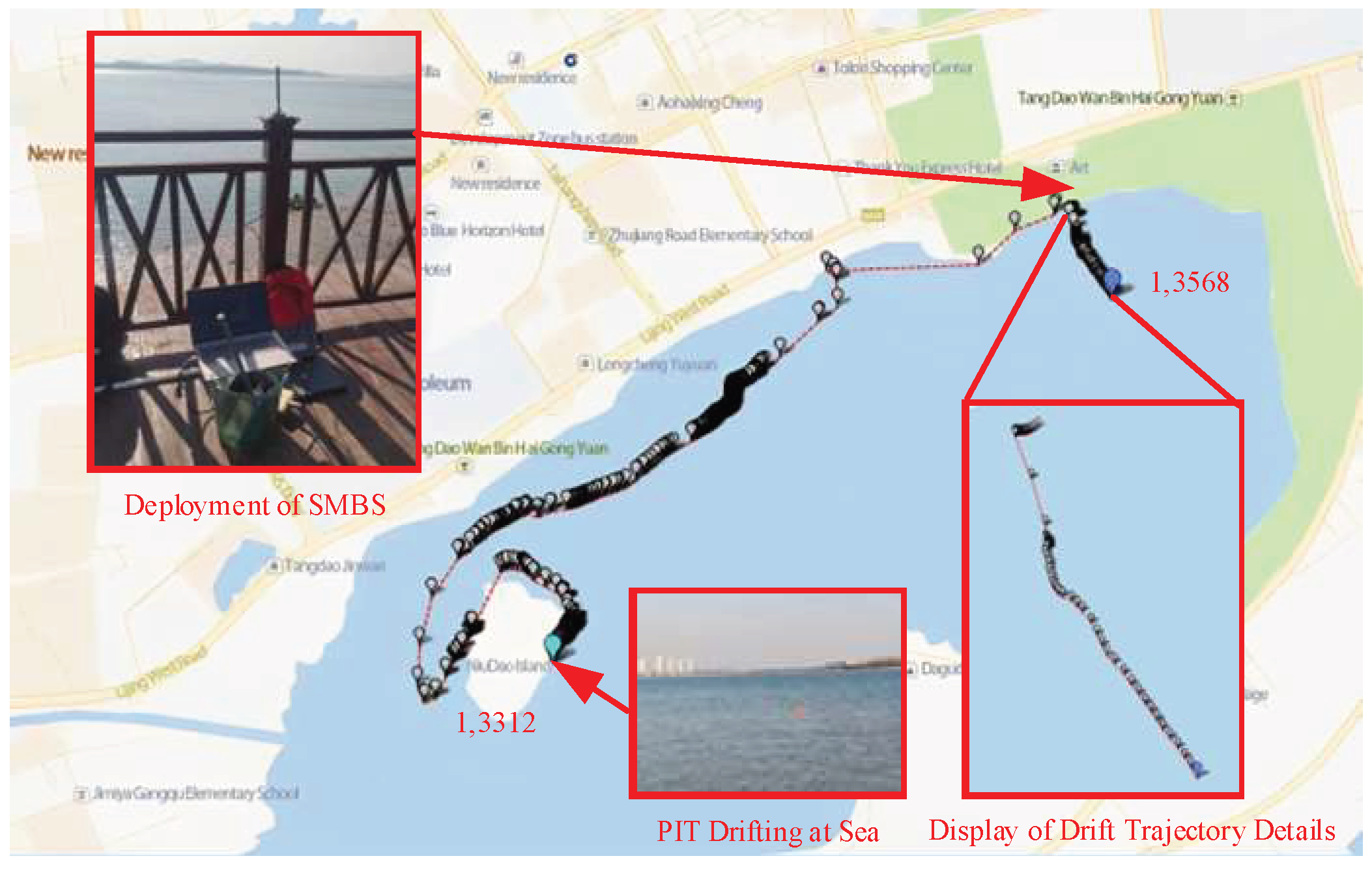
(2)
Rescue Information Transmission Stage: The 13568 was placed on the sea for free drifting, simulating a static drifting scene of a drowning person. The 13312 was dragged and moved by a speedboat, simulating the scene of a drowning person drifting with the waves. The drift trajectory of the sea comprehensive test is shown in Figure 16: the 13568 drifted freely at sea for 1 h, receiving a total of 120 alarm messages. The farthest communication distance was about 661.4 m, and the communication success rate was 100%. The 13312 drifted dynamically at sea for two hours (average speed: 3.7 m/s), receiving a total of 213 messages, with a maximum communication distance of approximately 3267.5 m and a communication success rate of 88.75%. During the process of towing 13312, the speedboat changed its course multiple times, and PIT was able to track and extract key positioning information in a timely manner and send it to SMBS.
(3)
Emergency Search and Rescue Phase: The rescue team carried out rescue PIT work based on the positioning data received by SMBS, and the rescue site is shown in Figure 17.
The results of the comprehensive maritime experiments show that LR-MPIBS can quickly detect incidents of personnel wearing PITs accidentally falling into the sea, and send rescue information to SMBS. About one minute after a person falls into the sea, PIT locates the location information of the person and prompts the rescue team to quickly rescue the person in distress. SMBS has a good dynamic and static positioning performance (positioning deviation less than 10 m), and the success rate of rescue information transmission exceeds 88.75%. The above data demonstrate the practicality of LR-MPIBS in quickly rescuing drowning personnel over short distances.

3.7. Performance Comparison

The performance of the LR-MPIBS designed in this paper is compared with the MPIBS from existing products and research institutions, as shown in Table 5. According to the table analysis, the endurance of LR-MPIBS exceeds 25 h, and the communication alarm cycle is 30 s. Compared to other MPIBS with alarm cycles exceeding 60 s, LR-MPIBS provides higher position transmission frequency while increasing endurance. It is worth noting that the battery capacity of LR-MPIBS is 1500 mAh, which is one-third of the battery capacity of other comparative systems. Therefore, LR-MPIBS can achieve smaller and more portable designs. LR-MPIBS can provide rescue teams with rescue information for drowning personnel within a 5 km range (with a success rate of over 85%). Key positioning data for the drifting trajectory of drowning personnel (with an accuracy of over 10 m) are also compressed into rescue information, which helps rescue teams improve the accuracy of predicting the drifting trajectory of drowning personnel.
Overall, LR-MPIBS can achieve rapid alarm for personnel falling into the water, which helps to improve the efficiency of rescue operations for personnel falling into the water at sea.

4. Conclusions

This paper describes in detail the design of a LoRa-based position-indicating beacon system with the objectives of rapid alarm, low power consumption, stable communication, and high reliability. The main results can be summarized as follows.
(1)
The design principles and methods of the falling water detection module are detailed, and the reliability of the circuit operation was tested. The FWD module can automatically detect and trigger startup after 3 s of falling into the water. Its current consumption during equipment shutdown is 10.1 µA, and its current consumption during water detection is less than 90 µA.
(2)
We analyzed the impact of the LoRa RF path impedance value on communication performance, and designed it to be 50 Ω through software simulation. The LoRa wireless communication protocol was designed, which includes the rescue protocol of PIT and the response protocol of SMBS. This aims to achieve reliable communication between personnel in distress and rescue teams.
(3)
The interference of power-supply ripple on RF was analyzed, along with the instabilities in the power-supply voltage caused by the sudden change in current during RF communication. In this study, we designed a power management module that can withstand a maximum transient current of 1 A, and its output voltage ripple is below 45 mV.
(4)
We designed positioning data processing algorithms, including those for verifying the effectiveness of positioning data, extracting key positioning data, and compressing key positioning data. The recognition rate of key positioning data was 97.67% and its compression rate was 50%.
(5)
The experimental results show that the system can automatically detect and sound the alarm for personnel drowning incidents. After the PIT is turned on, the search time for satellites does not exceed 50 s, the effective communication distance is no less than 5 km, and the battery life is 25 h during continuous operation. The experimental results are stable and reproducible. The marine comprehensive testing results of LR-MPIBS further demonstrate its practicality in the rescue process.

Author Contributions

Conceptualization, Z.L. and J.D.; data curation, Z.L. and J.D.; formal analysis, Z.L. and L.D.; funding acquisition, Z.L. and L.D.; investigation, Z.L. and J.D.; methodology, Z.L., J.D. and L.D.; project administration, Z.L.; resources, Z.L.; software, Z.L., J.D. and N.S.; supervision, Z.L. and L.D.; validation, Z.L., J.D. and Y.L.; visualization, Z.L. and J.D.; writing—original draft, Z.L. and J.D.; writing—review and editing, Z.L. and J.D. All authors have read and agreed to the published version of the manuscript.

Funding

This research was funded by the Qingdao Municipal Bureau of Science and Technology (grant number 22-3-3-hygg-3-hy).

Institutional Review Board Statement

Not applicable.

Informed Consent Statement

Not applicable.

Data Availability Statement

The data presented in this study are available on request from the authors. The data are not publicly available due to privacy.

Conflicts of Interest

The authors declare no conflicts of interest.

References

  1. Su, Z.; Liu, X.; Zheng, G.; Zhou, K.; Gao, S. Serviceability of the IAMSAR standard man overboard recovery maneuvers: A case-study of full-scale sea trials. Appl. Ocean Res. 2021, 114, 102782. [Google Scholar] [CrossRef]
  2. Armeniakos, C.K.; Nikolaidis, V.; Tsekenis, V.; Maliatsos, K.; Bithas, P.S.; Kanatas, A.G. Human fall detection using mmWaveradars: A cluster-assisted experimental approach. J. Ambient. Intell. Humaniz. Comput. 2023, 14, 11657–11669. [Google Scholar] [CrossRef]
  3. Zhang, J.; Wang, K.; Zhang, Y.; Gao, J. Design of underwater emergency positioning system based on BD/GPS. Foreign Electron. Meas. Technol. 2021, 40, 87–93. [Google Scholar] [CrossRef]
  4. Lin, W. Design and Realisation of Alarm Device for People Overboard; Dalian Maritime University: Dalian, China, 2011. [Google Scholar]
  5. Bing, Z. Research and Design of Maritime Search and Rescue System; Fudan University: Shanghai, China, 2013. [Google Scholar]
  6. Li, X.; Song, H.; Liu, C. Path loss modeling for wireless network deployment in water surface environments. IEEE Antennas Wirel. Propag. Lett. 2022, 21, 1090–1094. [Google Scholar] [CrossRef]
  7. El Agroudy, N.; Georgiades, G.; Joram, N.; Ellinger, F. RSSI overboard localization system for safe evacuation of large passengers ships. In Proceedings of the 13th Conference on Ph.D. Research in Microelectronics and Electronics, Taormina, Italy, 12–15 June 2017; Volume 2017, pp. 177–180. [Google Scholar] [CrossRef]
  8. Sheu, B.-H.; Yang, T.-C.; Yang, T.-M.; Huang, C.-I.; Chen, W.-P. Real-time Alarm, Dynamic GPS Tracking, and Monitoring System for Man Overboard. Sens. Mater. 2020, 32, 197. [Google Scholar] [CrossRef]
  9. Mao, X.; Liu, X.; Feng, T.; Chen, K. A communication protocol of man overboard system based on BeiDou. In Proceedings of the 17th International IEEE Conference on Intelligent Transportation Systems (ITSC), Qingdao, China, 8–11 October 2014; pp. 1910–1911. [Google Scholar] [CrossRef]
  10. Xiang, S.; Peiren, W.U. Maritime emergency SAR system based on BeiDou satellite navigation system. Command Control Simul. 2018, 40, 43–49. [Google Scholar]
  11. Gürüler, H.; Altun, M.; Khan, F.; Whangbo, T. Man overboard detection system using iot for navigation model. Comput. Mater. Contin. 2022, 71, 4955–4969. [Google Scholar] [CrossRef]
  12. Huang, P.-F.; Du, Z.-X.; Cheng, C.-F.; Chen, J.-H. The design and development of man overboard alarm and rescue terminal. J. Discret. Math. Sci. Cryptogr. 2016, 19, 649–661. [Google Scholar] [CrossRef]
  13. Dong, Z. Design and Implementation of the Miniature, Personal and Nautical AIS-EPIRB; Xi’an University of Electronic Science and Technology: Xi’an, China, 2014. [Google Scholar]
  14. Huanhuan, H. Study Emergency Position Indicating Radio Beacon on AIS; Dalian Maritime University: Dalian, China, 2011. [Google Scholar]
  15. Li, Y.; Chung, K.L.; Xie, S.; Yang, Y.; Wang, M.; Geng, X. An improved design of automatic-identification-system-based man overboard device: A multidisciplinary product. IEEE Access 2018, 6, 25220–25229. [Google Scholar] [CrossRef]
  16. Wu, H.-T. The design discussion of a self-powered automatic identification system sensor. IEEE Sens. J. 2023, 23, 20766–20772. [Google Scholar] [CrossRef]
  17. Hu, B. Research of Maritime Fallen Overboard Automatic Alarm System Based on Beidou; Shanghai Ocean University: Shanghai, China, 2016. [Google Scholar]
  18. Horstmann, T.; Michael, R.; Marco, R.; Simon, W. Evaluation of LoRa in a Real-World Smart City: Selected Insights and Findings. Mobile Communication—Technologies and Applications. In Proceedings of the 27th ITG-Symposium, Osnabrück, Germany, 10–11 May 2023; pp. 91–96. [Google Scholar]
  19. Yang, Y.J. Design and research of low-power wireless water quality sensor based on LoRa. China New Commun. 2021, 23, 10–11. [Google Scholar]
  20. Patriti, T.; Mirri, S.; Girau, R. A LoRa-mesh based system for marine Social IoT. In Proceedings of the IEEE 20th Consumer Communications & Networking Conference (CCNC), Las Vegas, NV, USA, 8–11 January 2023; Volume 2023, pp. 329–332. [Google Scholar] [CrossRef]
  21. Zhou, F.; Chen, H.; Zhang, P. Performance evaluation of maritime search and rescue missions using automatic identification system data. J. Navig. 2020, 73, 1237–1246. [Google Scholar] [CrossRef]
  22. Brojdo, S. Characteristics of the dielectric diode and triode at very high frequencies. Solid State Electron. 1963, 6, 611–629. [Google Scholar] [CrossRef]
  23. Sevin, A.; Bayilmiş, C.; Ertürk, I.; Ekiz, H.; Karaca, A. Design and implementation of a man-overboard emergency discovery system based on wireless sensor networks. Turk. J. Electr. Eng. Comp. Sci. 2016, 24, 762–773. [Google Scholar] [CrossRef]
  24. Satheesh, J.; Nair, A.P.; Devipriya, M.; Chithra, A.; Mahesh, G.; Jayasree, P.R. Wireless communication-based water surface cleaning boat. In Proceedings of the 4th International Conference on Trends in Electronics and Informatics (ICOEI), Tirunelveli, India, 15–17 June 2020; Volume 48184, pp. 716–720. [Google Scholar]
  25. Hoang, Q.L.; Jung, W.-S.; Yoon, T.; Yoo, D.; Oh, H. A real-time LoRa protocol for industrial monitoring and control systems. IEEE Access 2020, 8, 44727–44738. [Google Scholar] [CrossRef]
  26. Kang, E.; Min, W.; Choo, H. Stretchable helical antenna with an inverted-F feeding structure for man overboard devices. IEEE Antennas Wirel. Propag. Lett. 2021, 20, 2220–2224. [Google Scholar] [CrossRef]
  27. Kaur, M.; Kakar, S.; Mandal, D. Electromagnetic interference. In Proceedings of the 3rd International Conference on Electronics Computer Technology, Kanyakumari, India, 8–10 April 2011; pp. 1–5. [Google Scholar] [CrossRef]
  28. Dala, A.; Arslan, T. Design, implementation, and measurement procedure of underwater and water surface antenna for LoRa communication. Sensors 2021, 21, 1337. [Google Scholar] [CrossRef] [PubMed]
  29. Liu, Y.Y.; Dang, Y.M.; Xue, S.Q. Preliminary discussion of multipath effect model on the sea. J.Surv. Mapp. Sci. 2013, 1, 122–124. [Google Scholar]
  30. Yang, X.; Haas, K.A.; Fritz, H.M.; French, S.P.; Shi, X.; Neary, V.S.; Gunawan, B. National geodatabase of ocean current power resource in USA. Renew. Sustain. Energy Rev. 2015, 44, 496–507. [Google Scholar] [CrossRef]
  31. Zhao, H. On the link quality measurement in wireless sensor network. J. Northeast. Univ. Nat. Sci. Ed. 2008, 2, 193–196. [Google Scholar]
  32. Millero, F.J.; Feistel, R.; Wright, D.G.; McDougall, T.J. The composition of Standard Seawater and the definition of the Reference-Composition Salinity Scale. Deep Sea Res. Part I 2008, 55, 50–72. [Google Scholar] [CrossRef]
  33. Wu, J.; Cheng, L.; Chu, S. Modeling the leeway drift characteristics of persons-in-water at a sea-area scale in the seas of China. Ocean Eng. 2023, 270, 113444. [Google Scholar] [CrossRef]
  34. Qu, J.; Wang, J. A design and implementation of beidou beacon technology for therescue of the drowning personnel at sea. Electron. Meas. Technol. 2019, 42, 63–68. [Google Scholar] [CrossRef]
Figure 1. Application scenario of the LR-MPIBS.
Applsci 14 01231 g001
Figure 2. Architecture of the LR-MPIBS.
Applsci 14 01231 g002
Figure 3. Falling-water-detection module circuit.
Applsci 14 01231 g003
Figure 4. Power-management module circuit.
Applsci 14 01231 g004
Figure 5. Basic workflow of the LR-MPIBS.
Applsci 14 01231 g005
Figure 6. Physical devices of the LR-MPIBS. (a) Ship-mounted base station. (b) Position-indicating terminal.
Applsci 14 01231 g006
Figure 7. Analysis of the waveforms from the FWD module.
Applsci 14 01231 g007
Figure 8. Conductivity tests result.
Applsci 14 01231 g008
Figure 9. Beidou initial satellite-search performance results.
Applsci 14 01231 g009
Figure 10. Communication performance test environment.
Applsci 14 01231 g010
Figure 11. Communication performance tests result of LR-MPIBS.
Applsci 14 01231 g011
Figure 12. Test of the extracting of key positioning data.
Applsci 14 01231 g012
Figure 13. Results of the endurance test of PIT.
Applsci 14 01231 g013
Figure 14. Display of PIT wearing methods.
Applsci 14 01231 g014
Figure 15. Simulate man overboard and throwing PIT onto the sea surface to trigger activation.
Applsci 14 01231 g015
Figure 16. Drift trajectories recorded during sea trials.
Applsci 14 01231 g016
Figure 17. Rescue PIT.
Applsci 14 01231 g017
Table 1. Relationship between transmission line impedance value and communication distance.
RF transmission line width (mil)6.57.510.512.521.71
Simulated value of RF transmission line impedance (Ω)66.9164.7559.857.3650
Communication distance (m)28113128931263631
Table 3. Message body contents.
Field NameContentData TypeLength (Bytes)
Number informationBase-station numberChar16
Personnel numberChar
Latest valid positioning dataLongitude dataFloat8
Latitude dataFloat
(m)th key positioning informationLongitude incrementShort4
Latitude incrementShort
(m − 1)th key positioning informationLongitude incrementShort4
Latitude incrementsShort
Short
Short
(1)th key location informationLongitude incrementsShort4
Latitude incrementShort
Functional information0x22/0x23Char1
Table 4. Response information content.
Field NameContentsData TypeLength (Bytes)
ID informationPersonnel IDChar8
Base-station IDChar8
Functional information0x10/0x11Char1
Table 5. Performance comparison of LR-MPIBS with MPIBS from existing products and research institutions.
InstituteThis WorkGD Panco Co., Ltd.XING YU Co., Ltd.Dalian Scientific Test Inst [34]XIDIAN UNIVERSITY [13]NUC [3]
Communication/Positioning MethodsLoRa/BDSRSMC/BDSRSMC/BDSLoRa/BDSAIS/GPSGPRS/GPS
Startup Time For Man
Overboard Detection
3 s5 s5 s>60 s-4~5 s
RNSS Cold Start50 s≤60 s≤40 s≤-27 s≤60 s≤
Positioning Error10 m<5 m<5 m<10 m<10 m<10 m<
Rescue Information
Transmission Cycle
30 s60 s60 s60 s60 s300 s
Communication Distance≥5 KmThe Coverage Area Of BDS≥3 Km≥9 Km-
Communication Success Rate≥85%≥95%≥95%--≥98%
Key Information Extraction
Of Drift Trajectory
YeaNoNoNoNoNo
Endurance≥25 H≥30 H≥17 H-≥48 H≥8 H
Volume (mm)87 × 60 × 22101 × 62 × 2595 × 59 × 23---
ADDR Guangdong, ChinaNanjing, ChinaDalian, ChinaXi’an, ChinaShanxi, China
Disclaimer/Publisher’s Note: The statements, opinions and data contained in all publications are solely those of the individual author(s) and contributor(s) and not of MDPI and/or the editor(s). MDPI and/or the editor(s) disclaim responsibility for any injury to people or property resulting from any ideas, methods, instructions or products referred to in the content.

