1. Introduction
Soft soil is widely distributed close to lakes and the middle and lower reaches of rivers all over the world. The Pearl River Delta, located on the southeast coast of China, serves as one example of such an area. The physical and mechanical properties of soft soils are highly intricate, characterized by low strength, high moisture content, high compressibility, and high sensitivity to external disturbances [
1]. Improper treatment of the soft soil base can result in a range of practical engineering issues, including uneven ground settlement and large post-work settlement over a longer period. These issues can impact the structural stability and long-term safety of various buildings constructed on such soil [
2,
3]. Hence, it is imperative to improve soft soil conditions before utilizing it as a foundation for any building. Vacuum preloading, surcharge preloading, and combined preloading are commonly used practical methods to enhance soft soil conditions [
4,
5,
6,
7,
8].
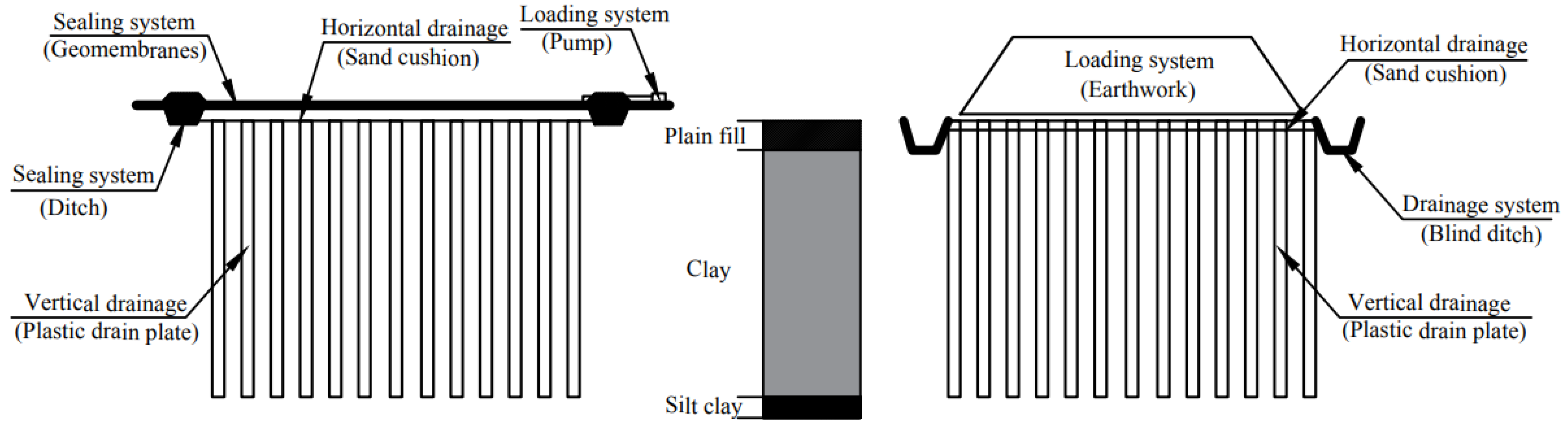
Figure 1 illustrates the schematics of vacuum preloading and surcharge preloading methods. These methods aim to drain the pore water from the ground through a pre-loaded vertical and horizontal drainage system, and as the pore water dissipates, the pore volume of the soil then decreases, consolidation and settlement of the foundation occurs, and the effective stress and strength of the foundation soil gradually increases. The drainage consolidation models of the ground by preloading are presented [
9,
10,
11,
12,
13].
Some innovations are provided to improve the vacuum preloading method. For example, the expansion of dissolved gas in water, thermal preloading, and prefabricated boosters are used to accelerate water drainage [
6,
7,
14,
15]. The optimal surcharge preloading rate minimizes the lateral displacement [
16], and the sealing membrane with clay reduces the total cost by replacement [
17].
Some case studies have shown that vacuum preloading resulted in more consolidation degree and less consolidation settlement than surcharge preloading [
18,
19,
20,
21]. The consolidation settlement is composed of immediate, primary, and secondary consolidation settlements [
5,
22]. The immediate and primary consolidation settlements of the ground are mostly completed during the preloading stage. However, during the service stage, when the ground is used as a foundation for buildings, secondary consolidation settlements continue to occur due to soft soil creep under the additional stress. The uneven secondary consolidation settlement in the service stage will reduce the safety of the building on the ground and will even destroy the building. Therefore, it is necessary to investigate the impact of vacuum and surcharge preloading on the immediate, primary, and secondary consolidation settlement of ground to minimize the detrimental effects of uneven secondary consolidation settlement on the building [
19,
23]. However, such effects have not been thoroughly studied.
This study outlines an improvement project for soft soil ground in Zhuhai City and conducts a case comparative study to investigate the diversity of primary and secondary consolidation settlement resulting from ground improvement by vacuum preloading and surcharge preloading, including the effects of excess pore water pressure, horizontal displacement, and soil strength.
2. Site Condition
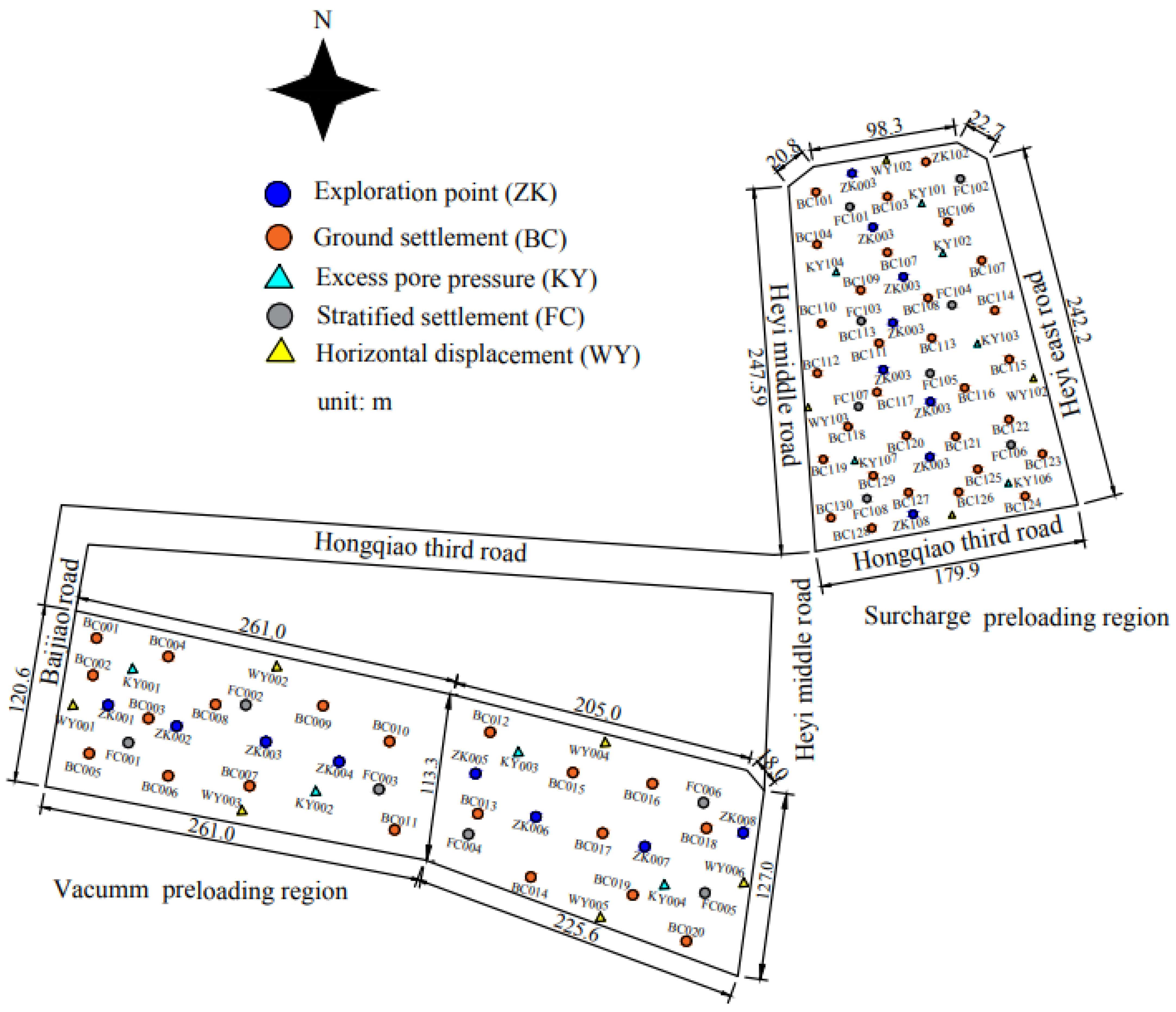
This improvement project is located in Zhuhai City, Guangdong Province, between Heyi East Road and Heyi West Road. This project has an L-shaped site with a total area of 128,000 m² and is divided into a vacuum preloading region and a surcharged preloading region with an area of 53,000 m² and 75,000 m², respectively, as depicted in
Figure 2.
Table 1 tabulates the profile of the strata and the mechanical parameters of each soil stratum at the site. The table reveals that the site is primarily composed of a soft soil stratum, which has a thickness of 19.24 m below ground level, as determined by geotechnical investigation. The layout of exploratory holes from the geotechnical investigation is illustrated in
Figure 2. The groundwater table is situated at a depth of 1.37 m from ground level.
3. Construction Processes
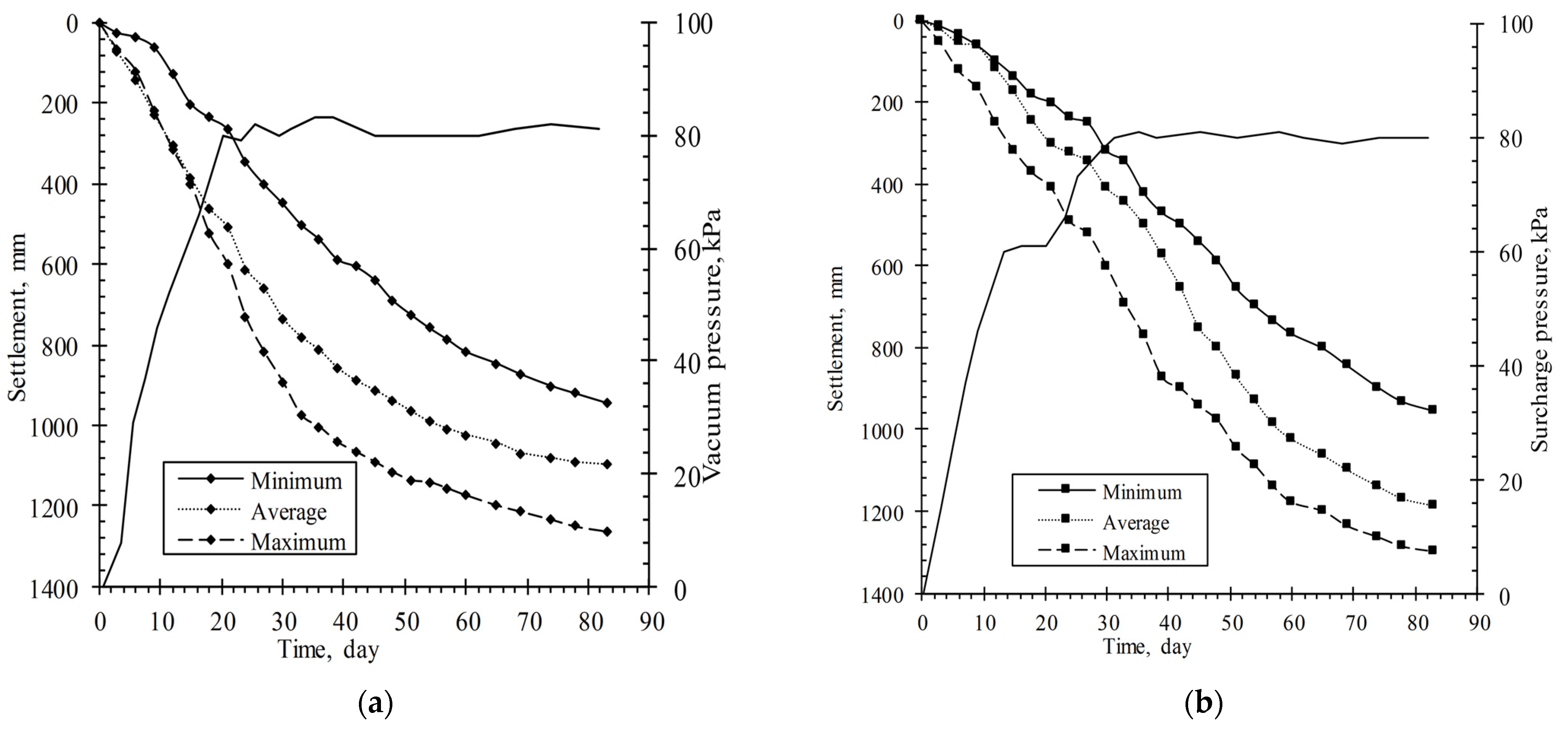
Before the implementation of improvements, the length of the PVDs and the total pressures of surcharge preloading and vacuum preloading were fixed at 21.0 m and 80 kPa, respectively. According to the Code for Foundation Treatment, the PVDs were a cross-section of 100 mm × 4 mm with an equivalent diameter of 66 mm, and they were designed to be installed in a triangular pattern at a spacing of 1.2 m in the two improving regions. Secondly, a 0.5 m thick sand cushion was laid on the two regions. In the vacuum preloading region, the vertical draining pipe, vacuum pump, horizontal draining pipe, sealing membrane (geo-members), and sealing ditch were successively installed by on-scene operation. The vacuum pump was then started, and the vacuum pressure under the membranes achieved −80 kPa on the 20th day, and this was maintained for 63 days. The total period of vacuum preloading was 83 days, and in the surcharge preloading region, the water collection well, sealing membrane, blind ditch, and surcharge load were also successively applied by on-scene operation. The surcharge load material was selected to be clay soil with a unit weight of 17.8 kN/m3, and the surcharge fill was constructed up to 4.5 m heigh with an equivalent pressure of 80.1 kPa in 30 days, which then lasted for 53 days.
During the total period of vacuum preloading and surcharge preloading, various parameters were monitored in the two regions targeted for improvement, including ground settlement, stratified settlement, horizontal displacement, and excess pore water pressure. The number and sequence of monitoring points and holes are tabulated in
Table 2, and the layout of monitoring points and holes is plotted in
Figure 2. In order to monitor the settlement amount and settlement process of each soil layer and to grasp the deformation of each soil layer under vacuum, ground vertical settlement and horizontal displacement were monitored using a LeicaNA730 balance level with an accuracy of 1.2 mm/km and a LeicaTZ08 total station with an accuracy of 1 s, respectively. In order to monitor the settlement amount and settlement process of each soil layer and to grasp the deformation of each soil layer under vacuum pre-pressure and mound pre-pressure, eight CJY-7090 high-precision stratified settlement gauges with a measurement accuracy of 1 mm were fixed at intervals of 3.0 m in a 24 m stratified settlement tube, respectively, and the stratified settlement of the soil was obtained by monitoring the synchronous sinking amount of the magnetic settlement ring fixed on the settlement tube with the settlement of the foundation. It is worth mentioning that the accuracy of the measurement results is greatly influenced by the selection of the reference point, and it is necessary to ensure that the settlement tube enters the soil-bearing layer, otherwise, the compression and settlement of the soil at the bottom of the tube produces relatively large measurement errors.
The pore water pressure was monitored using a KXR-3030 vibrating wire pore water pressure transducer, buried at the monitoring location in a one-hole multi-point pattern. The KXR-3030 vibrating wire pore water pressure transducer has a resolving power of ≤0.08% F.S (Full scale) and a combined error of ≤ 1.5% F.S. It mainly consists of a probe, a frequency reading instrument, and a cable, which translates the change in pore water pressure by measuring the frequency change of the internal steel string. Seven vibrating wire pore water pressure transducers were buried at 3.0 m intervals in each excess pore water pressure hole from a depth of 3 m to 21 m.
The shear strength of the soil is related to the stability of the foundation, and the direct shear test is a common method to determine the shear strength of the soil, with the advantages of simple operation and high-test efficiency. The static load test is currently one of the most intuitive and reliable testing methods to determine the bearing capacity [
24,
25,
26]. Most foundations should be tested for bearing capacity using static load tests. In this case, after improvement, soil strength and pile friction resistance of improved soil was presented by direct shear test and field static load test, respectively.
4. Calculation of Primary and Secondary Settlement
Based on the mechanics of soil consolidation, the ground settlement is composed of instant settlement
(), primary consolidation settlement
(), and secondary consolidation settlement (
) caused by creep. Therefore, the final settlement by the consolidation method is presented. The final settlements (
) of two improved regions are also analyzed by the consolidation model method proposed by:
where
is average ground and strata consolidation settlement at time of
, and
and
are the primary consolidation settlement and secondary consolidation settlement caused by creep at time
.
During the primary consolidation settlement stage,
is very small and is therefore ignored. Then:
The primary consolidation settlement and its rate are written as:
where
and
are the primary consolidation settlement and its rate, respectively.
is the average of consolidation degree by
, where
is the loading rate of 80/20 and 80/30 kPa/d for vacuum and surcharging preloading, respectively;
is the cumulative loads (80 kPa); and
and
are the start time and end time for load No.1, respectively. When the conditions of vertical and inward radial drainage are applied,
,
, where
,
.
and
are the horizontal and vertical consolidation coefficients (cm
2/s), respectively.
, where
k,
e,
and
are listed in
Table 1. In the paper,
.
Substituting
in Equation (3), the following can be obtained:
Equation (4) is the first order differential equation of
, proposed by Asaoka [
27]. Then, substituting
in Equation (4) with Equation (2), the following is obtained:
Equation (5) shows that the average ground settlement rates () is liner to the with the slope () and intercept ( fitted by least square method.
Where
,
is the sum of
and
, and is denoted as
.
is calculated by:
and based on the measured settlement,
is also rewritten as:
so
was deduced and calculated by:
Then,
is presented by:
During the secondary consolidation settlement stage, the increment of
is very small and keeps a constant of
, then:
The
is analyzed by the Voigt–Kelvin model [
23], and is presented by:
where
is the secondary settlement rate;
and
is the elastic model of spring and viscosity coefficient of Newton dashpot in the Voigt–Kelvin model; and
is loading on the ground.
So, during the secondary consolidation stage, the relationship between consolidation settlement rate and the consolidation settlement is also a line with the slope
() and intercept (
), and
and
are fitted by the least square method. The final consolidation settlement is presented by:
Equation (11) is solved by:
So , . When t = 83 d, .
5. Results and Discussions
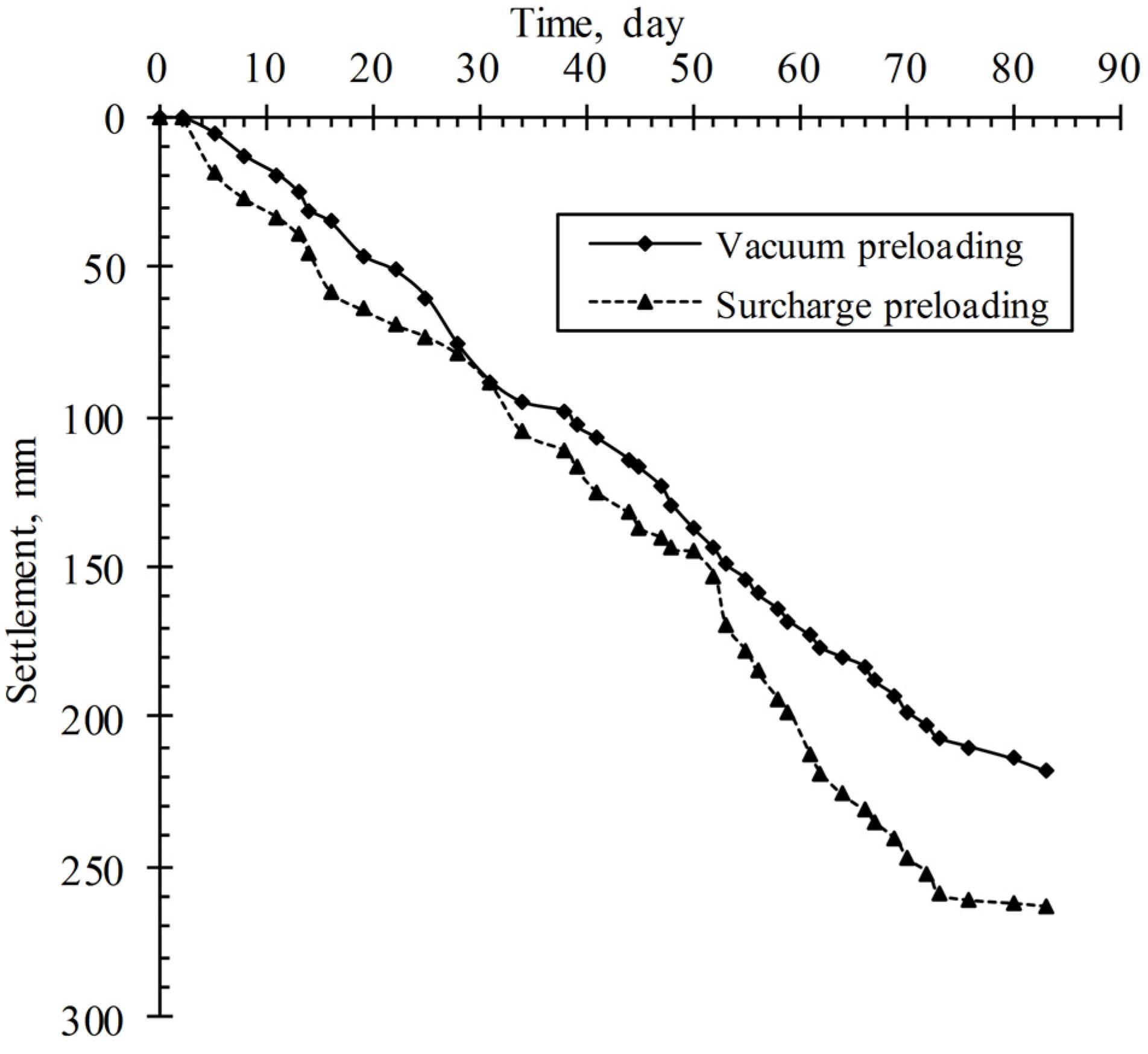
5.1. Measured Settlements
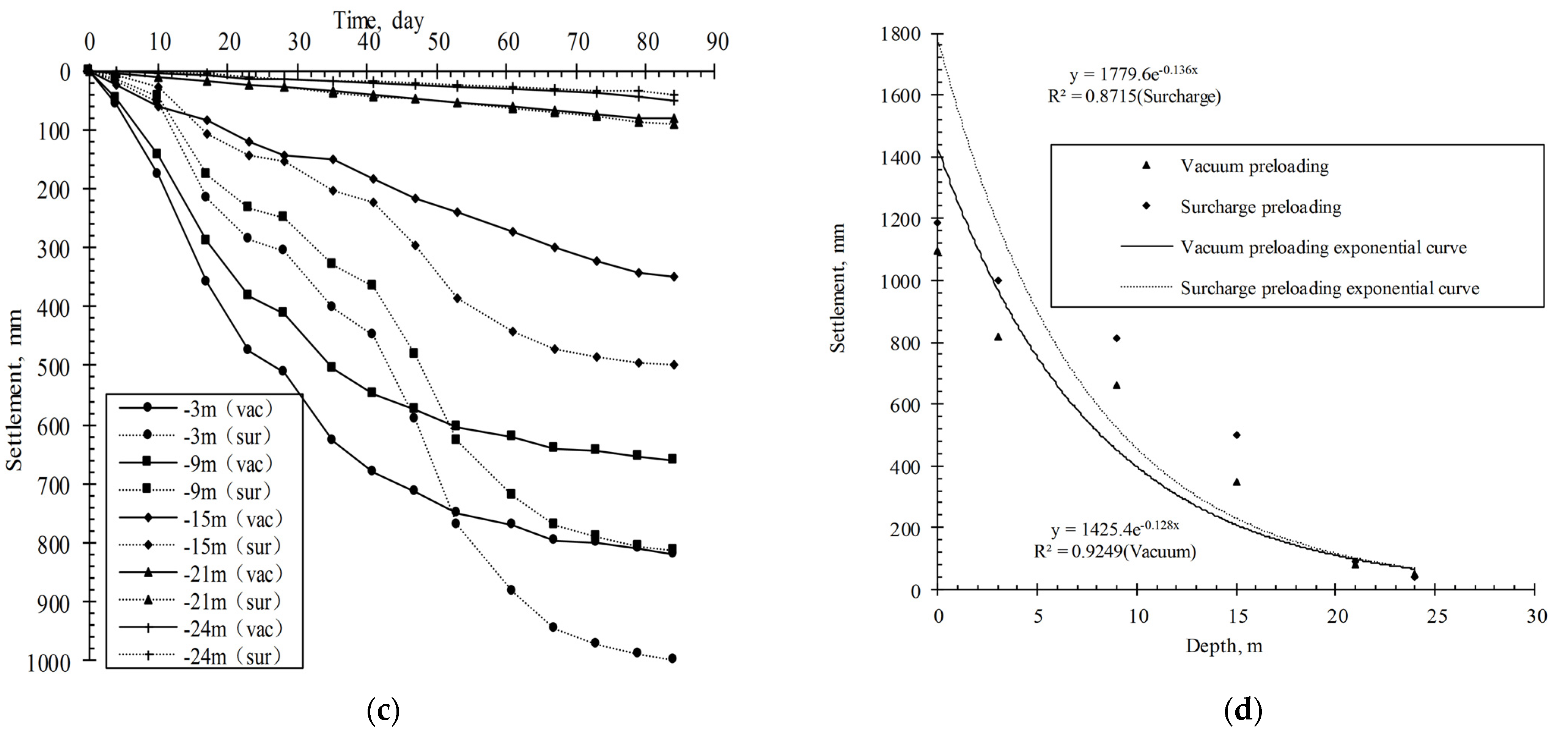
Figure 3 and
Table 3 show the ground settlements (
) and the stratified settlements (
) in the vacuum and surcharge preloading regions. As shown in
Figure 3 and
Table 3, on the 83rd day, the central
and
in the vacuum preloading region are 0.7 to 0.93 times that in the surcharge preloading region.
These ratios belong in the range from 0.8 to 1.0 provided by Chai [
28].
Figure 3 also shows that
reduce along depth and have a good fitness by negative exponential function with correlation coefficients of 0.93 and 0.87, respectively.
The consolidation degree,
, is calculated by the ratio of
to the final average settlements of ground and strata (
), predicted by the hyperbolic method with the formulas
and
.
is the measured ground and stratified settlement (mm) on the 20th day and 30th day for vacuum and surcharge preloading with 80 kPa, respectively;
and
are constants.
and
are tabulated in
Table 3.
Table 3 shows that
of foundation depth from 0 m to 15 m by the vacuum preloading is 1% greater than the one of surcharge preloading, while the
of vacuum at a depth of 15–21 m is 3% to 5% smaller than the one of surcharge.
Figure 3c shows the curves of the stratified settlements. In contrast to surcharge preloading, vacuum preloading reinforcement of soft foundations exhibits an accelerated increase in soil strength during the initial stages, followed by a deceleration in the later stages of reinforcement. Conversely, surcharge preloading demonstrates a more gradual increase in soil strength throughout the reinforcement process [
29]. This distinction is attributed to the disparate reinforcement mechanisms inherent to each preloading method.
Vacuum preloading employs an impermeable plastic film and geotextile sealing to strengthen soft ground foundations. By generating negative pressure within the soil, vacuum pumps facilitate the gradual extraction of soil pore water and air, leading to a continuous decrease in pore water pressure and an increase in the foundation’s effective stress. The vacuum pressure’s direct action on the fluid within the soil pores and indirect action on the soil skeleton via the pore fluid approximates an isotropic isobaric situation, enabling immediate application of the set load value. Consequently, a larger initial settlement is attained, and ground settlement remains relatively uniform [
22,
30].
In contrast, surcharge preloading applies the external load directly to the soil skeleton or particles, necessitating a stepwise loading process that precludes a one-time application of the set load value. Moreover, trapped air bubbles within the soil cannot be discharged during the extrusion process, potentially obstructing the pores and reducing soil permeability. This effect decelerates the consolidation process, resulting in a consolidation rate inferior to that of vacuum preloading.
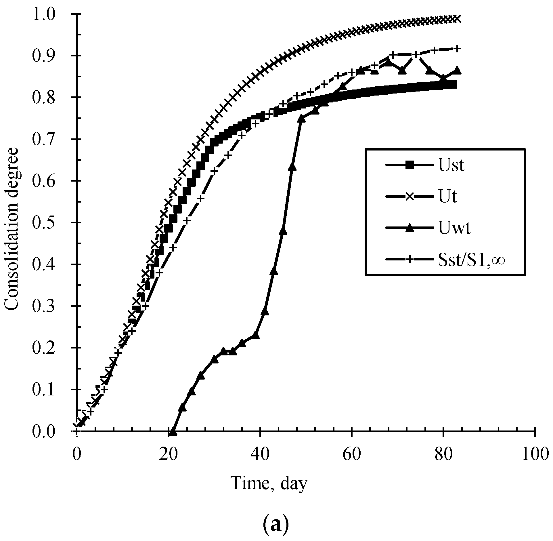
5.2. Primary and Secondary Settlement Analysis
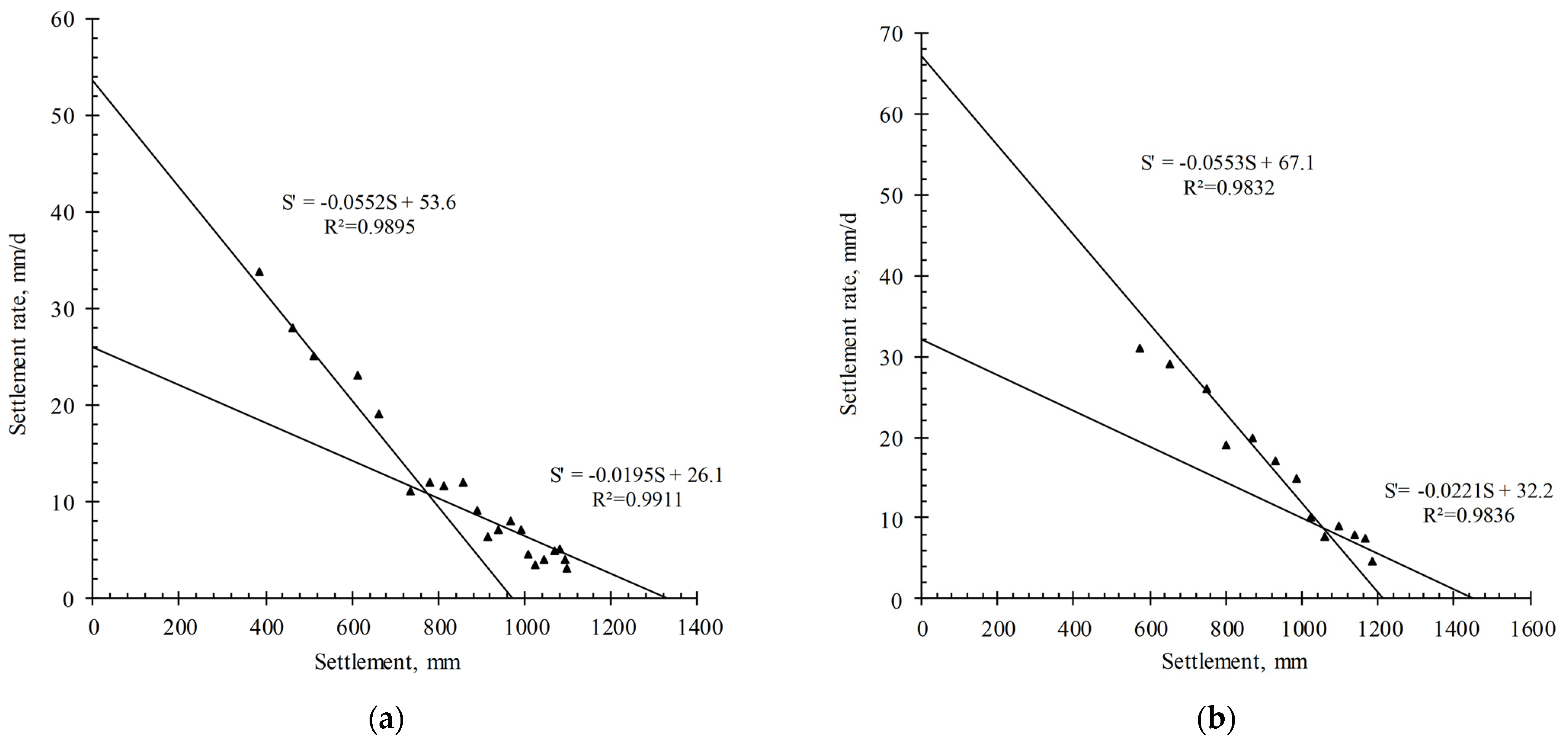
Figure 4 illustrates the correlation between
and
for both vacuum preloading and surcharge preloading. Using the slopes and intercepts of the
curve in
Figure 4 and Equations (8), (9), (12), and (13),
,
,
, and
are calculated and tabulated in
Table 4. Then,
,
, and
are calculated as 4.19 MPa, 6.83 MPa, and 4726.80 MPa/d in the surcharge preloading region, while they are 4.48 MPa, 4.67 MPa, and 3433.90 MPa/d in the vacuum preloading region.
Table 4 shows that the instant settlement,
, the primary consolidation settlement,
and the secondary consolidation settlement^,
, of vacuum preloading account for 28.2%, 44.7%, and 27.1% of the final settlements,
, while the ones of surcharged loading do 26.7%, 55.5%, and 17.0% of
. This means that the
during vacuum preloading is 1.6 times that during surcharge preloading. The reason for this is speculated as follows: Firstly, in
Section 5.1 on the 83rd day, the
of vacuum preloading is less than the one of surcharge preloading. In other words,
of the vacuum preloading is greater than the one of the surcharge preloading. Secondly, the surcharge preloaded foundation undergoes an additional stress field by a similar loading method for preloading and service stage, while the vacuum preloaded one is subjected to a negative pressure seepage field in the preloading stage and to an additional stress field in the service stage.
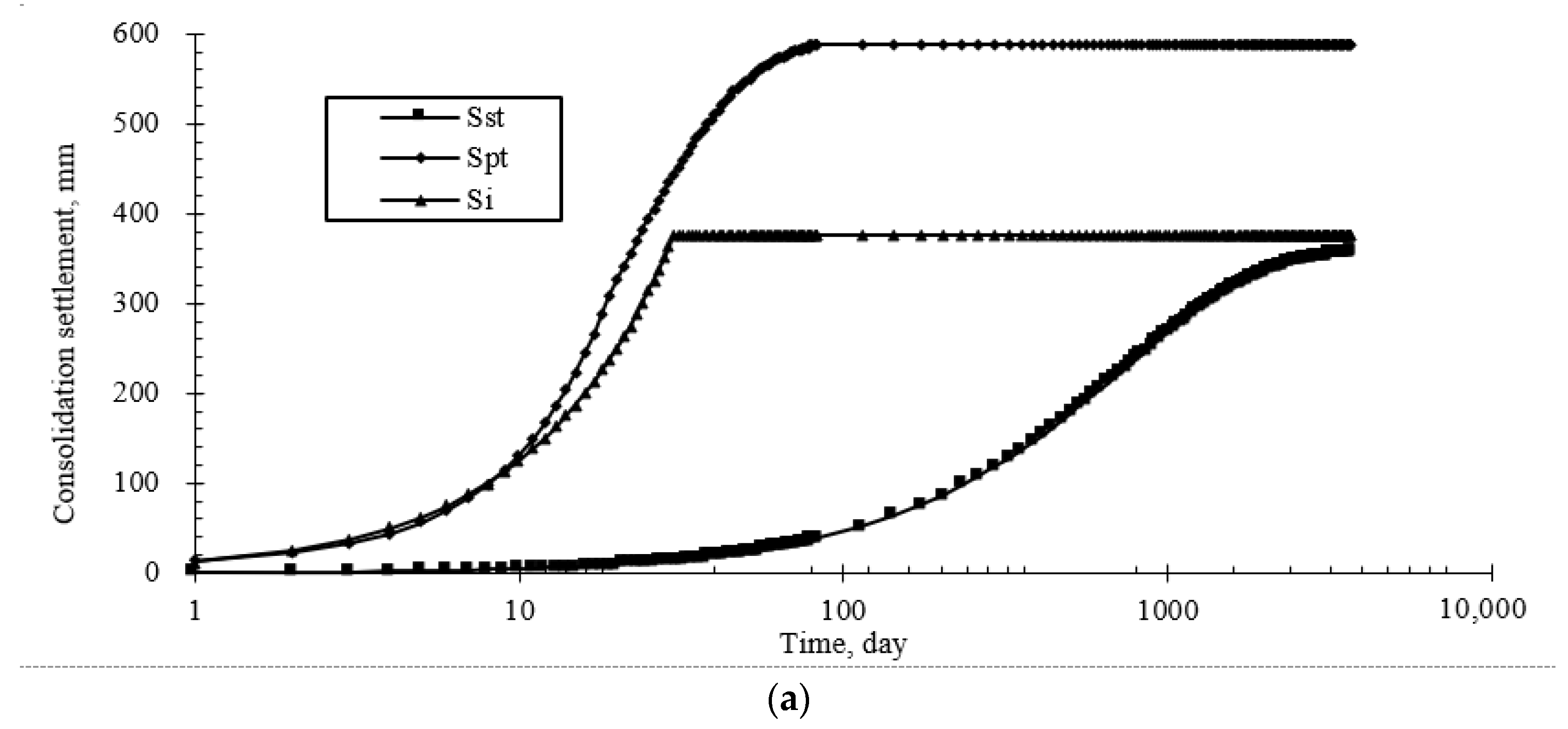
Figure 5 depicts the predicted curves for
,
, and
plotted against time. From
Figure 5 it can be deduced that after preloading,
and
tend to stabilize within 83 days, while
is smaller. In the service after the 83rd day, the
is still increasing for a long time of 10 ten years and is dominated by
. If the
of the preloading improved ground is over excessive, this may result in adverse settlement and settlement differences during the life of the building, reducing the serviceability of the foundations.
During the primary consolidation phase, soil consolidation primarily arises from the expulsion of air and free water within the pores. Conversely, secondary consolidation chiefly occurs due to the reorganization of soil grain structure and the creep of bound water films on soil grain surfaces. As illustrated in
Figure 5, the duration required for vacuum preloading consolidation to achieve settlement stability is notably longer compared to surcharge preloading consolidation. The reason for this may be that the vacuum preloading method acts on the pore water vapor fluid in the soil, and as pore water and gas dissipate, the pore space between soil particles gradually expands, inducing the rearrangement and compaction of soil particles without incurring shear damage or particle breakage. In contrast, the external load of surcharge preloading is applied directly to the soil skeleton or particles. The compression or disintegration of the skeleton prompts the translation or rotation of clay agglomerates, culminating in the internal cementation fracture of these agglomerates. Macroscopically, this process manifests as creep deformation of the soil. However, due to the rearrangement and fragmentation filling of soil particles, the soil becomes more compact and exhibits enhanced settlement consolidation [
19,
22,
30].
Therefore, the surcharge preloading has priority compared with vacuum preloading in reducing the ground settlement of ground during its service.
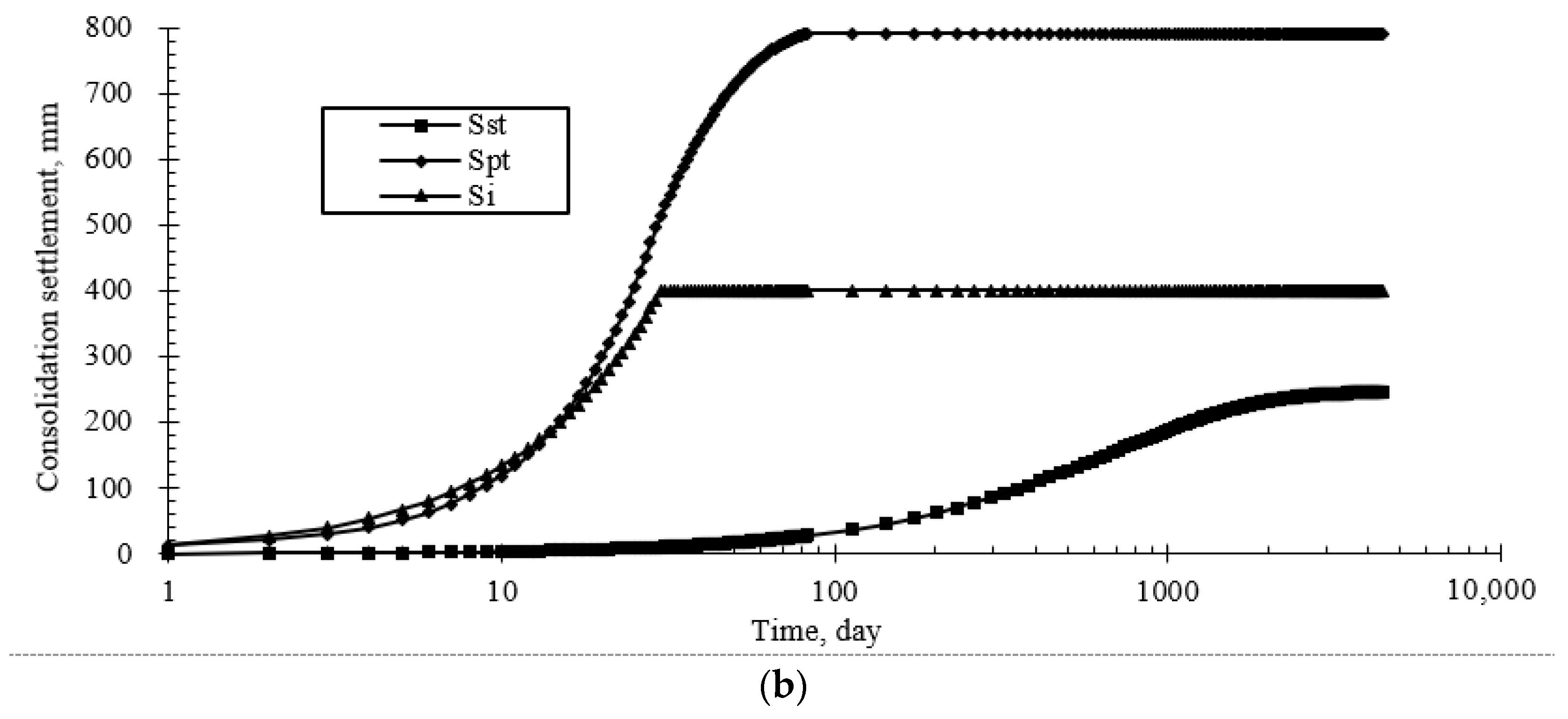
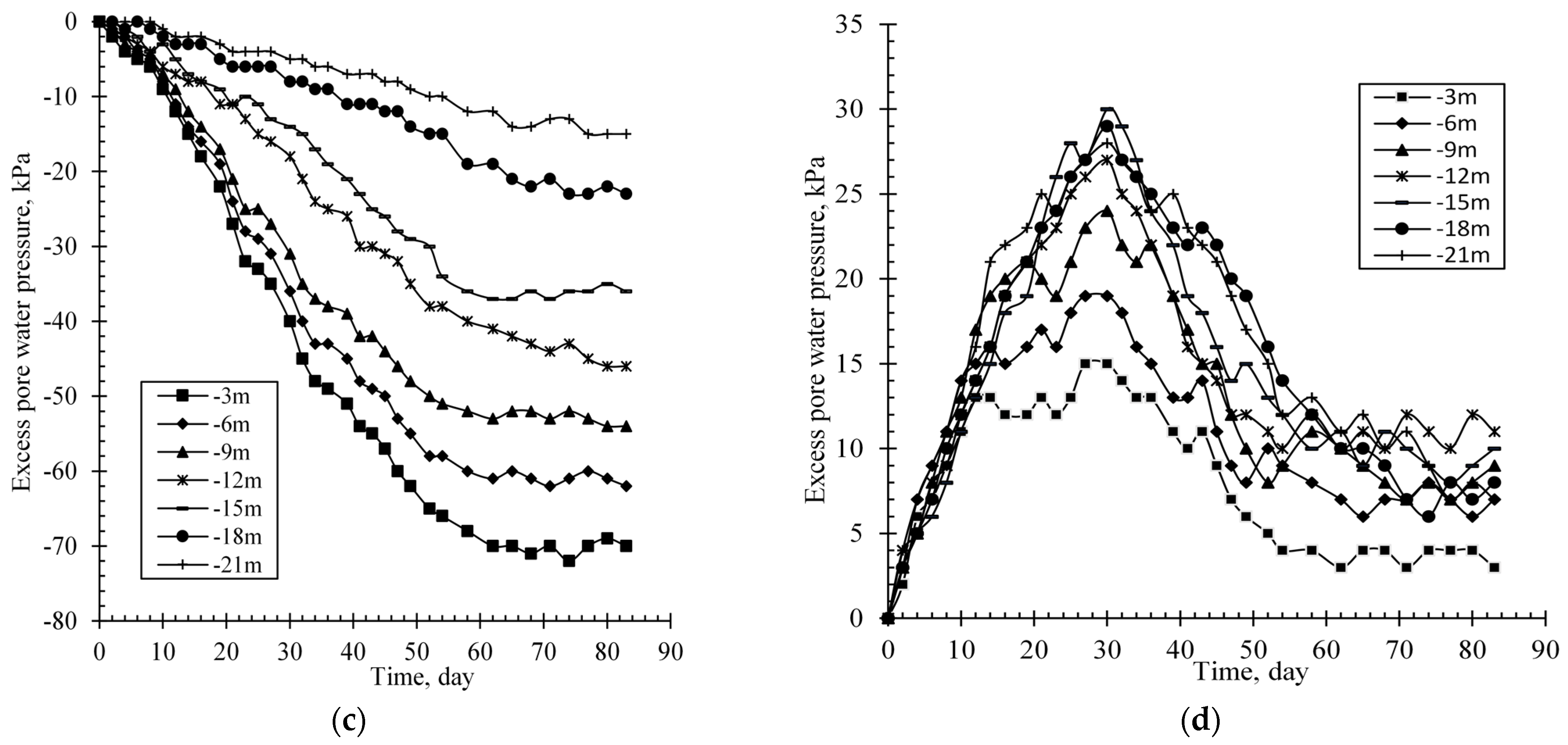
5.3. Relationship between Excess Pore Water Pressures and Primary Consolidation Settlement
Figure 6 plots the average excess pore water pressures (
). As shown in
Figure 6, the
monotonously increases up to the maximums on the 63rd day, then basically remains stable in vacuum preloading. On the 63rd day, the
of vacuum preloading decays linearly from −70 kPa to −10 kPa along the depth of the ground, with an attenuation coefficient of 3.1 kPa/m. The reason for this is the PVDs’s block, bending, and brakeage induced by stratified settlement [
6,
9,
17,
31,
32,
33,
34]. The
of surcharge preloading reaches maximum on the 30th day, then dissipates up to the minimums on the 53rd day. The
of surcharge preloading on the 30th day is piecewise linear along depth, i.e., it increases from 15 kPa to 30 kPa with depth in the range of 3–15 m, and slightly reduces to 27 kPa with depth in the range of 15–21 m. The
monotonously increases up to the maximum on the 63rd day, then basically remains stable in vacuum preloading. This shows existents in soil structure compression and stress redistribution during the consolidation process [
5].
The consolidation degrees (
) are plotted in
Figure 6 and tabulated in
Table 5.
is calculated using
by the hyperbolic method with the formula
,
,
, where
refers to the measured average excess pore water pressure (kPa) at any depth on the 20th day and 30th day in vacuum and surcharge preloading, respectively.
is the difference between
and its maximum (kPa).
is the final excess pore water pressure.
and
are the constants. As shown in
Table 5, the
decreases with the depth from 3 m to 15 m, then increases from 15 to 21 m on the 83rd day.
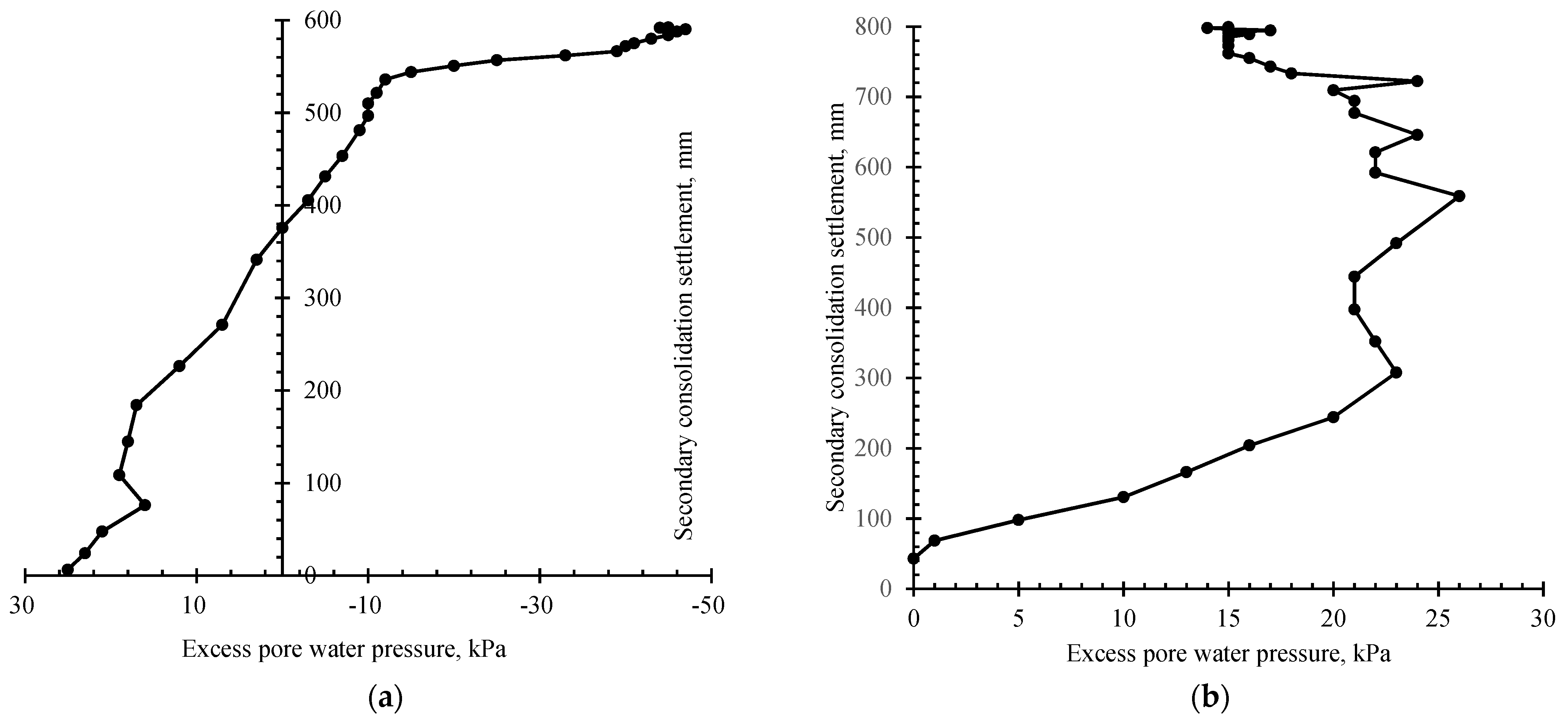
Figure 7 plots the primary consolidation settlement (
) vs.
. The secondary consolidation settlement (
) during preloading retains a low level, and the effect of
on
can be ignored.
Figure 7a shows that during the vacuum preloading, the
obviously increases by 540 mm, equal to 90% primary consolidation settlement, with
ranging from 0 kPa to −40 kPa, while it gently increases by approximately 60 mm with
over −40 kPa. Therefore, it can be deduced that
with −40 kPa is an important value during the monitoring of
,
in the vacuum preloading. As shown in
Figure 7b, during the surcharge preloading,
slowly increases with
beneath 20 kPa and increases significantly with
between 20 kPa and 25 kPa.
5.4. Horizontal Displacement and Soil Strength and Effects on Primary Consolidation Settlement
Figure 8 plots the horizontal displacement.
Figure 8 shows that horizontal displacement induced by vacuum preloading with a maximum of 263 mm (point WY104) moving toward the center is 1.2 times the one by surcharge preloading, with a maximum of 218 mm (point WY002) moving in the negative direction. Because of the horizontal displacement and
increase with the time, it can be presumed that
grows with the increase in horizontal displacement [
35].
After vacuum and surcharge preloading, the cohesion () and internal friction angle () of clays increase from 2.9 kPa to 4.3~4.4 kPa and from 2.30° to 2.92~2.99°, respectively, and the pile side friction resistance increases from 7.0 kPa to 10.2~11.3 kPa.
With the application of vacuum preloading, cohesion, friction angle, and pile lateral frictional resistance experienced an increase of 48%, 27%, and 46%, respectively. Furthermore, when surcharge preloading pressure was applied, the improvements in cohesion, friction angle, and pile lateral frictional resistance were observed to be 52%, 31%, and 61%, respectively. Similarly, the deformation parameters such as , , and were also improved, and the increasing of , , and reduce the and . These findings underscore the efficacy of both vacuum preloading and the application of additional preloading pressure in bolstering the soil’s mechanical properties and overall performance; the results indicate a substantial enhancement of soft soil ground properties in the improvement project.
5.5. Discussions
The measured ground settlement difference for vacuum preloading is smaller than that of surcharge preloading. This may be because the vacuum preloading applies a relatively more uniform pressure on the ground than surcharge preloading, which initializes the trapezoid pressure with small value at the sides and a large one in the center. This is verified by Zhang et al. [
19]. Therefore, the vacuum preloading benefits to reduce differential ground settlement [
20,
36,
37].
As can also be seen from
Figure 3c, the stratified settlements at the depth of 21 m are less than 100 mm, approximately 7% of the ground settlements, in the vacuum and surcharge preloading. Therefore, the depth of 21 m can be regarded as the influence depth of vacuum preloading and surcharge preloading.
Figure 6 shows that the
decreases as depth increases, while there are increases at the depth of 21 m in the two preloading regions. This may be because the permeability of soil (k) and the void ratio (e) of this site decreases with increasing depth, while sharply increasing at a depth of approximately 21 m close to the stratigraphic boundary between clay and silt clay (seen
Table 1) [
34,
36,
38]. The sharp increasing of strata permeability coefficient will induce the increase in strata
and has little effect on the ground
.
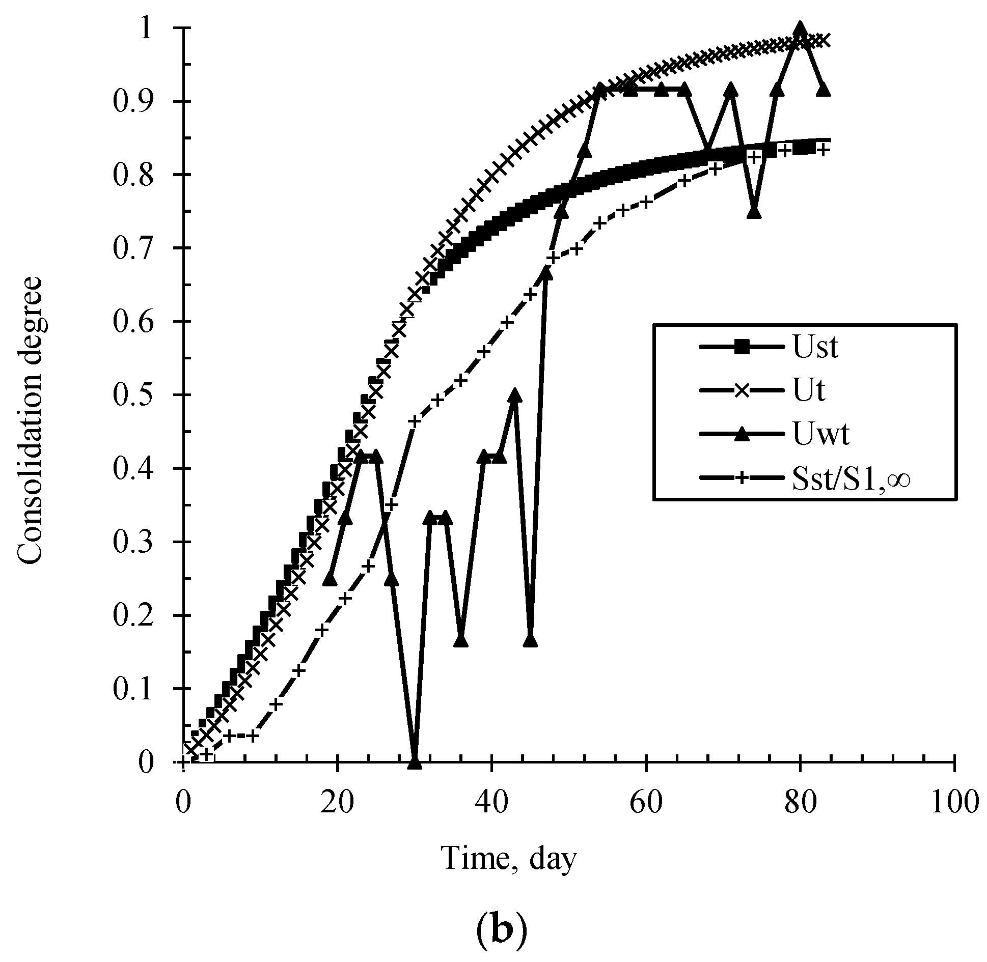
The consolidation degrees denoted as
,
,
, calculated by the consolidation model method [
39],
and
for vacuum and surcharging preloading, respectively, are plotted in
Figure 9.
Figure 9 shows that in vacuum and surcharging preloading, the
,
are close to each other within 35 days after preloading, while they deviate significantly after the 35th day. On the 83rd day, the sequence of consolidation degree from the maximum to the minimum is
,
,
. The
is less than
within 50 days and is relatively close to
after the 50th day.
Based on the definition of
and
, the ratio of
to
is calculated by:
The develops with the increasing of the difference between and . On the 83rd day, the accounts for 9% of in vacuum preloading and 10% in surcharge preloading.
In the drainage consolidation improvement of soft soil, vacuum preloading is more beneficial to reduce the uneven settlement, but in order to reduce the ground settlement of ground during its service, surcharge preloading should be given priority compared with vacuum preloading.
6. Conclusions
Based on the improvement engineering of soft soil ground in Zhuhai City on the Pearl River Delta, a case comparative study on vacuum preloading and surcharge preloading was performed. The conclusions are drawn below:
- (1)
Compared to the surcharge preloading method, the vacuum preloading method is more efficient in terms of consolidation time and settlement reduction. However, surcharge preloading results in smaller secondary consolidation settlements than vacuum preloading and should be given priority in order to reduce the settlement foundation in the service stage.
- (2)
The primary consolidation settlement () quickly increases up to 90% of the total primary consolidation settlement (), with an increase in the average excess pore water pressures () of less than −40 kPa in vacuum preloading, while it also quickly increases, with the average excess pore water pressures () hovering between 20 kPa and 25 kPa in surcharge preloading.
- (3)
The sharp increase in strata permeability coefficient will induce the increase in strata consolidation degrees and has little effect on the ground consolidation degrees.
- (4)
The vacuum preloading is more beneficial to reduce uneven settlement, and the surcharge preloading is more beneficial to reduce ground settlement during its service.
Author Contributions
Conceptualization, L.F. and S.P.; methodology, L.F.; software, Z.X.; validation, Z.X.; formal analysis, Z.X.; investigation, L.F.; resources, L.F.; data curation, Z.X.; writing—original draft preparation, Z.X.; writing—review and editing, L.F. and S.P.; visualization, L.F.; supervision, S.P.; project administration, L.F.; funding acquisition, L.F. and S.P. All authors have read and agreed to the published version of the manuscript.
Funding
The research was funded by the National Natural Science Foundation of China (Grant No. 52174100 and No. 51674287), and the National Science Foundation of Hunan Province, China (Grant No. 2021JJ30834).
Institutional Review Board Statement
Not applicable.
Informed Consent Statement
Not applicable.
Data Availability Statement
The data that support the findings of this study are available upon request from the authors.
Acknowledgments
This study was supported by t National Natural Science Foundation of China (Grant No. 52174100 and No. 51674287), and the National Science Foundation of Hunan Province, China (Grant No. 2021JJ30834). We would also like to sincerely thank Guoliang Chen, Kejia Zhang, Jinghong Zheng, and Yuankai Zeng, who gave valuable comments on both the pre-conceptualization and post-revision of the manuscript, which greatly improved the manuscript.
Conflicts of Interest
The authors declare no conflict of interest.
References
- Lei, H.; Wang, L.; Zhang, W.; Jiang, M.; Bo, Y.; Song, W.; Cao, Q. Geotechnical properties of the South China Sea soft soil: A comparative study with the soils from Bohai Sea and Yellow Sea. Bull. Eng. Geol. Environ. 2023, 82, 158. [Google Scholar] [CrossRef]
- Indraratna, B. Recent Advances in Vertical Drains and Vacuum Preloading for Soft Ground Stabilisation. In Proceedings of the Proceedings of the 19th International Conference on Soil Mechanics and Geotechnical Engineering, Seoul, Republic of Korea, 17–22 September 2017. [Google Scholar]
- Indraratna, B. Recent Advances in the Application of Vertical Drains and Vacuum Preloading in Soft Soil Stabilisation. Aust. Geomech. J. 2010, 45, 1–44. [Google Scholar]
- Kjellman, W. Consolidation of Clayey Soils by Atmospheric Pressure. In Proceedings of a Conference on Soil Stabilization; Massachusetts Institute of Technology: Cambridge, MA, USA, 1952; pp. 258–263. [Google Scholar]
- Liu, H.-l.; Chu, J. A new type of prefabricated vertical drain with improved properties. Geotext. Geomembr. 2009, 27, 152–155. [Google Scholar] [CrossRef]
- Artidteang, S.; Bergado, D.T.; Saowapakpiboon, J.; Teerachaikulpanich, N.; Kumar, A. Enhancement of efficiency of prefabricated vertical drains using surcharge, vacuum and heat preloading. Geosynth. Int. 2011, 18, 35–47. [Google Scholar] [CrossRef]
- Wang, J.; Cai, Y.; Ni, J.; Geng, X.; Xu, F. Effect of sand on the vacuum consolidation of dredged slurry. Mar. Georesour. Geotechnol. 2018, 36, 238–244. [Google Scholar] [CrossRef]
- Indraratna, B.; Rujikiatkamjorn, C.; Ameratunga, J.; Boyle, P. Performance and prediction of vacuum combined surcharge consolidation at Port of Brisbane. J. Geotech. Geoenviron. Eng. 2011, 137, 1009–1018. [Google Scholar] [CrossRef]
- Cascone, E.; Biondi, G. A case study on soil settlements induced by preloading and vertical drains. Geotext. Geomembr. 2013, 38, 51–67. [Google Scholar] [CrossRef]
- Mohamedelhassan, E.; Shang, J. Vacuum and surcharge combined one-dimensional consolidation of clay soils. Can. Geotech. J. 2002, 39, 1126–1138. [Google Scholar] [CrossRef]
- Chai, J.C.; Carter, J.P.; Hayashi, S. Vacuum consolidation and its combination with embankment loading. Can. Geotech. J. 2006, 43, 985–996. [Google Scholar] [CrossRef]
- Perera, D.; Indraratna, B.; Leroueil, S.; Rujikiatkamjorn, C.; Kelly, R. Analytical model for vacuum consolidation incorporating soil disturbance caused by mandrel-driven drains. Can. Geotech. J. 2017, 54, 547–560. [Google Scholar] [CrossRef]
- Chu, J.; Yan, S. Estimation of degree of consolidation for vacuum preloading projects. Int. J. Geomech. 2005, 5, 158–165. [Google Scholar] [CrossRef]
- Chai, J.; Miura, N.; Bergado, D.T. Preloading clayey deposit by vacuum pressure with cap-drain: Analyses versus performance. Geotext. Geomembr. 2008, 26, 220–230. [Google Scholar] [CrossRef]
- Sun, L.; Guo, W.; Chu, J.; Nie, W.; Ren, Y.; Yan, S.; Hou, J. A pilot test on a membraneless vacuum preloading method. Geotext. Geomembr. 2017, 45, 142–148. [Google Scholar] [CrossRef]
- Chai, J.; Rondonuwu, S.G. Surcharge loading rate for minimizing lateral displacement of PVD improved deposit with vacuum pressure. Geotext. Geomembr. 2015, 43, 558–566. [Google Scholar] [CrossRef]
- Long, P.V.; Nguyen, L.V.; Bergado, D.T.; Balasubramaniam, A.S. Performance of PVD improved soft ground using vacuum consolidation methods with and without airtight membrane. Geotext. Geomembr. 2015, 43, 473–483. [Google Scholar] [CrossRef]
- Lam, L.G.; Bergado, D.T.; Hino, T. PVD improvement of soft Bangkok clay with and without vacuum preloading using analytical and numerical analyses. Geotext. Geomembr. 2015, 43, 547–557. [Google Scholar] [CrossRef]
- Zhang, Z.; Ye, G.B.; Xu, Y. Comparative analysis on performance of vertical drain improved clay deposit under vacuum or surcharge loading. Geotext. Geomembr. 2018, 46, 146–154. [Google Scholar] [CrossRef]
- Ding, J.; Wan, X.; Zhang, C.; He, Z.; Zhao, L. Case Study: Ground Improvement of Yangtze River Floodplain Soils with Combined Vacuum and Surcharge Preloading Method. Int. J. Geomech. 2019, 19, 05019008.1–05019008.13. [Google Scholar] [CrossRef]
- López-Acosta, N.; Espinosa-Santiago, A.L.; Pineda-Núez, V.; Ossa, A.; Mendoza, M.J.; Ovando-Shelley, E.; Botero, E. Performance of a test embankment on very soft clayey soil improved with drain-to-drain vacuum preloading technology. Geotext. Geomembr. 2019, 47, 618–631. [Google Scholar] [CrossRef]
- Yu, H.; Lu, C.; Chen, W.; Tian, H. An insight into the creep mechanisms of a clayey soil through long-term consolidation tests. Bull. Eng. Geol. Environ. 2021, 80, 9127–9139. [Google Scholar] [CrossRef]
- Kumarage, P.I.; Gnanendran, C.T. Long-term performance predictions in ground improvements with vacuum assisted Prefabricated Vertical Drains. Geotext. Geomembr. 2019, 47, 95–103. [Google Scholar] [CrossRef]
- Fellenius, B.H.; Harris, D.E.; Anderson, D.G. Static loading test on a 45 m long pipe pile in Sandpoint, Idaho. Can. Geotech. J. 2004, 41, 613–628. [Google Scholar] [CrossRef]
- Lv, A.; Liang, J.; Zou, S.; Chen, X.; Li, Q. The device and experimental study of the monitoring of the layered soil settlement. J. Phys. Conf. Ser. 2021, 1930, 012017. [Google Scholar] [CrossRef]
- Lei, H.; Feng, S.; Wang, L.; Jin, Y. Field instrumentation and settlement prediction of ground treated with straight-line vacuum preloading. Geomech. Eng. 2019, 19, 447–462. [Google Scholar]
- Asaoka, A. Observational Procedure of Settlement Prediction. Soils Found. 1978, 18, 87–101. [Google Scholar] [CrossRef] [PubMed]
- Chai, J.; Carter, J.; Hayashi, S. Ground deformation induced by vacuum consolidation. J. Geotech. Geoenviron. Eng. 2005, 131, 1552–1561. [Google Scholar] [CrossRef]
- Xu, H.; Deng, X.J.; Qi, Y.Z. Development of shear strength of soft clay under vacuum preloading. Chin. J. Geotech. Eng. 2010, 32, 6. (In Chinese) [Google Scholar]
- Mo, H.; Wang, J.; Lin, Y. Macro and micro anakyses of effectiveness by vacuumprekoading treatment of soft soil. Chin. J. Rock Mech. Eng. 2013, 32, 6. (In Chinese) [Google Scholar]
- Bergado, D.T.; Balasubramaniam, A.; Fannin, R.J.; Holtz, R.D. Prefabricated vertical drains (PVDs) in soft Bangkok clay: A case study of the new Bangkok International Airport project. Can. Geotech. J. 2002, 39, 304–315. [Google Scholar] [CrossRef]
- Long, P.V.; Bergado, D.T.; Giao, P.H.; Balasubramaniam, A.; Quang, N.C. Back analyses of compressibility and flow parameters of PVD improved soft ground in Southern Vietnam. In Proceedings of the 8th International Conference on Geosynthetics, Yokohama, Japan, 18–22 September 2006; pp. 465–468. [Google Scholar]
- Chai, J.C.; Miura, N.; Nomura, T. Effect of hydraulic radius on long-term drainage capacity of geosynthetics drains. Geotext. Geomembr. 2004, 22, 3–16. [Google Scholar] [CrossRef]
- Wang, P.; Wu, J.; Ge, X.; Chen, F.; Yang, X. Non-uniform Consolidation of Soil and Influence of Corresponding Clogging Effect During Vacuum Preloading. Int. J. Geosynth. Ground Eng. 2022, 8, 58. [Google Scholar] [CrossRef]
- Mesri, G.; Khan, A.Q. Ground Improvement Using Vacuum Loading Together with Vertical Drains. J. Geotech. Geoenviron. Eng. 2012, 138, 680–689. [Google Scholar] [CrossRef]
- Feng, S.; Bai, W.; Lei, H.; Song, X.; Liu, W.; Cheng, X. Vacuum preloading combined with surcharge preloading method for consolidation of clay-slurry ground: A case study. Mar. Georesour. Geotechnol. 2023, 1–14. [Google Scholar] [CrossRef]
- Wu, Y.; Jiang, H.; Lu, Y.; Sun, D. Experimental study on treatment of waste slurry by vacuum preloading with different conditioning agents. Geomech. Eng. 2019, 17, 543–551. [Google Scholar]
- Lei, H.; Lu, H.; Liu, J.; Zheng, G. Experimental study of the clogging of dredger fills under vacuum preloading. Int. J. Geomech. 2017, 17, 04017117. [Google Scholar] [CrossRef]
- Wang, Z.L.; Zheng, M.X.; Li, Y.C. Research on mathematic model method for calculating pre-consolidation pressure and its application. Yantu Lixue/Rock Soil Mech. 2005, 27, 1587–1590. [Google Scholar]
| Disclaimer/Publisher’s Note: The statements, opinions and data contained in all publications are solely those of the individual author(s) and contributor(s) and not of MDPI and/or the editor(s). MDPI and/or the editor(s) disclaim responsibility for any injury to people or property resulting from any ideas, methods, instructions or products referred to in the content. |
© 2023 by the authors. Licensee MDPI, Basel, Switzerland. This article is an open access article distributed under the terms and conditions of the Creative Commons Attribution (CC BY) license (https://creativecommons.org/licenses/by/4.0/).


