Communication

Theoretical Evaluation for Soil Thrust of Single-Track System over Clay Slope via Upper Bound Analysis

1
Department of Civil Engineering, Inha University, 100 Inha-ro, Michuhol-gu, Incheon 22212, Republic of Korea
2
Department of Civil and Environmental Engineering, Incheon National University, 119 Academy-ro, Yeonsu-gu, Incheon 22012, Republic of Korea
*
Author to whom correspondence should be addressed.
Appl. Sci. 2023, 13(9), 5222; https://doi.org/10.3390/app13095222
Submission received: 13 March 2023 / Revised: 5 April 2023 / Accepted: 15 April 2023 / Published: 22 April 2023
(This article belongs to the Special Issue Soft Soil Mechanics and Foundation Consolidation)

Abstract

:
This study aimed to theoretically evaluate soil thrust on a clay slope as a reaction force associated with the motion of an off-road tracked vehicle. The existing concept of the potential failure modes of a clay block on flat ground has extended to determine the soil thrust of sloped clay ground. Based on the upper-bound limit analysis, the soil thrust under the most critical failure was derived for three potential failure modes: block, triangular-wedge, and trapezoidal-wedge failures. Specifically, the influence of the slope angle, the shear strength of clay, the weight of a vehicle, and the geometry of a track system on the soil thrust was investigated. Only the block and triangular wedge failure modes were able to occur, and the geometry of a single-track system could lead to different failure modes. Under the block failure mode, the soil thrust decreased as the slope became stiff, and the vehicle weight increased. On the other hand, the soil thrust decreased as the slope angle decreased under the triangular-wedge failure mode.

1. Introduction

The interactions between ground conditions and wheeled or tracked vehicles have long been studied for the design and operation of off-road vehicles and terrain-working machinery, which has come to be known as terramechanics [1]. One of the major objectives of this research area is to investigate the performance of vehicles or machines associated with their operational environment, which is not only limited to various ground conditions on Earth but has been extended to the lunar surface [2]. Due to the ARTEMIS mission [3], increasing attention has been paid to the mobility of lunar roving vehicles (e.g., [4,5]). Demanding subsea industrial activities, such as underwater construction and mining, have also brought interest in the performance of underwater tracked vehicles against seabed conditions (e.g., [6,7]).
One of the most critical components in the performance of wheeled or tracked vehicles is the tractive performance, or mobility, on the natural terrain surface. This tractive performance indicates how a vehicle can effectively thrust off of unpaved ground surfaces; vehicles can move forward when the thrust force can overcome the resistance to motion [4]. For off-road tracked vehicles, the shear resistance of the soil along the soil–track system constitutes the thrust force, which is known as soil thrust [1]. One of the pioneering studies on the soil thrust of track systems was that of the study in [8]. This study derived theoretical expressions of soil thrust under a rectangular block failure using elasticity theory. Considering the plastic state of soils underneath the track system, empirical relationships for the soil thrust were presented for sandy soils based on experimental studies (e.g., [9,10,11]). Recently, the soil thrust of clay ground was analytically derived through an upper-bound limit analysis followed by experimental verification [12]. However, little attention has been paid to soil thrust considering sloped ground.
In this study, the upper-bound limit analysis for the soil thrust of a single-track system over flat clay ground by [12] was extended to account for sloped ground conditions. A typical continuous-track system interacting with clay ground was adopted, and three potential failure modes associated with each single-track system, a track place and a grouser, were investigated to evaluate the soil thrust along the clay slope. The upper bound solution was based on the plane-strain conditions under undrained conditions considering the shearing mechanism between the clay and the single-track system. The following notations and symbols are used throughout: bold-faced letters denote tensors, and the symbol ‘·’ denotes a single contraction of adjacent indices of two tensors (e.g., a b = a i b i or c d = c i j d j k ).

2. Upper-Bound Solution

A typical continuous-tracked vehicle on a slope with an angle of ψ is schematically depicted in Figure 1. The continuous track is connected through a series of single-track systems, each consisting of a track plate and a grouser. It is worth noting that the overall stability of a vehicle in terms of bearing capacity and deformation was not considered in this study. Only the soil thrust associated with the tractive performance along the slope of a vehicle was investigated. The total soil thrust of a continuous-track system is known to be consistent with the integrated soil thrust developed from each single-track system [10,13].
As can be seen in Figure 1, a clay slope is defined by the angle ψ, which may be from 0 to less than π / 2 . A rigid single-track system using the homogeneous ground condition of the Tresca model with the associated flow rule is assumed. Considering the shearing mechanism between the clay and single-track system, the plane-strain conditions with an undrained state is also postulated [14,15,16].
Figure 2 presents a schematic diagram of a soil block associated with a single-track system along the movement of a tracked vehicle on a clay slope. The coordinate system x-y is defined such that the x-axis is aligned parallel to the slope. Note that F x denotes the soil thrust; F v indicates the magnitude of the overburden force of a track system due to the weight of the vehicle, where the direction of the gravitational field is pointed downward along the vertical direction. Therefore, we may express the resultant external force, F , acting on a clay block on the slope as:
F = F x + F v sin ψ e x + F v cos ψ e y ,
where e x and e y denote the unit vectors of the corresponding coordinate system; F x is the soil thrust; and F v is the magnitude of the overburden force of the single-track system due to the weight of the vehicle. Following the method in [12], upper-bound analyses of three potential failure modes (block, triangular-wedge, trapezoidal-wedge) were conducted to investigate the soil thrust of each failure mode associated with a clay slope.
The following summarizes the assumptions made throughout this study:
  • A soil thrust of a single-track system under sloped ground conditions was investigated based on an upper-bound analysis;
  • The overall stability of a vehicle in terms of bearing capacity and deformation was not considered;
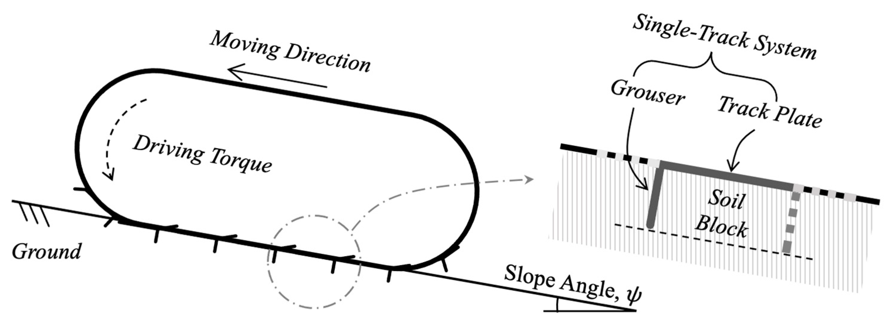
  • Three potential failure modes (block, triangular-wedge, and trapezoidal-wedge) were considered between a single-track system and clay slope;
  • The plane-strain condition with an undrained state was also postulated;
  • A rigid single-track system with the homogeneous ground conditions of the Tresca model with the associated flow rule was assumed.

3. Upper-Bound Solution for Different Potential Failure Modes on a Clay Slope
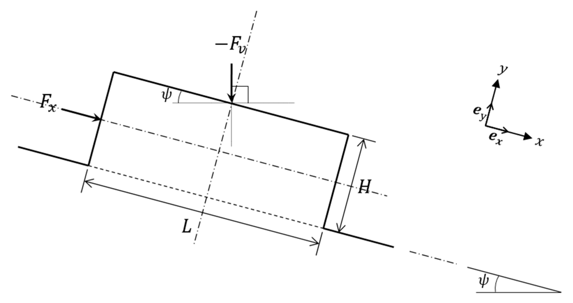
3.1. Block Failure

Figure 3 shows the potential block failure mode of clay due to the movement of a track system on a slope. The inclination of the slope is defined by ψ , where the failure line is assumed to be parallel to the clay slope. In this failure mode, the movement of the clay block defined by θ = π / 2 is described by the velocity V that is parallel to the slope surface. Therefore, the total external power, that is, the rate of work, can be calculated as:
P = F V = F x + F v sin ψ , F v cos ψ V , 0 P = F V = F x + F v sin ψ V ,
where V is the magnitude of the velocity V. Considering the speed of the track system, the failure mechanism is governed by the undrained strength of the clay ( c u ). Accordingly, the dissipation rate followed by the failure line can be expressed simply as:
D = c u L V .
Since the total external work is fully dissipated upon failure, i.e., P = D , the soil thrust can be written as:
F x = c u L F v sin ψ ,
which yields a consistent soil thrust with [12] for the flat clay ground ( ψ = 0 ). It is noted that the soil thrust becomes zero when:
F v = c u L sin ψ .
To showcase the influence of F v on F x , different values of F v were selected, and the normalized soil thrust values F x / c u are depicted in Figure 4. Note that values of c u and L of 10 kPa and 0.15 m were adopted as an example. Please refer to [12] for the background of the parameter selections. Different from flat clay ground, the soil thrust F x was affected by F v , which was directly related to the weight of the vehicle when there exists any slope in the clay ground. In addition, the soil thrust tended to decrease as the slope became stiff under the given vehicle weight ( F v ) and undrained shear strength of the clay ( c u ) . Although the shear resistance of clay along the failure line is a given condition regardless of a vehicle and ground inclination, the combination of the vehicle weight and the slope could diminish the soil thrust under the block failure mode.

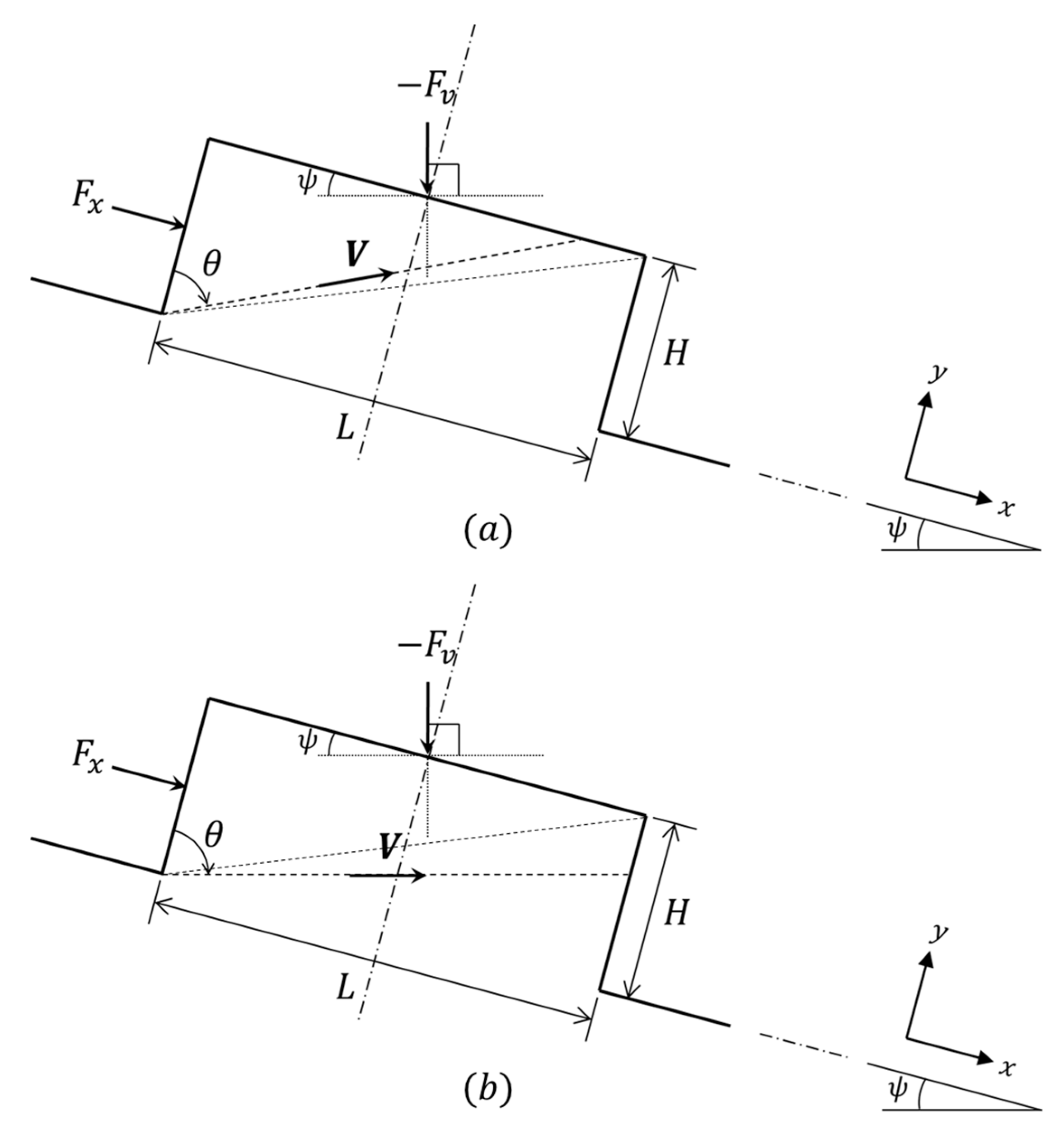
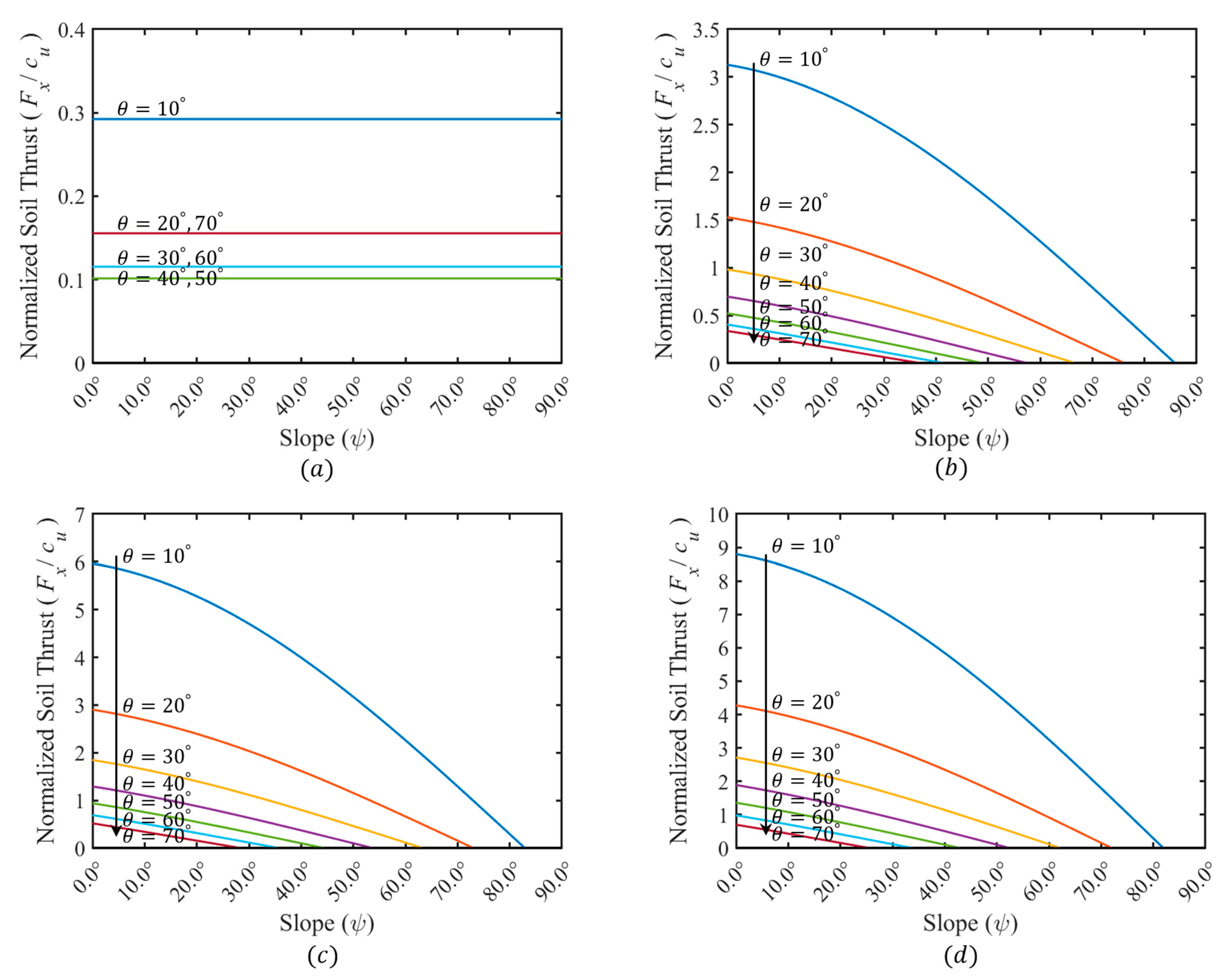
3.2. Triangular-Wedge Failure

A potential triangular-wedge failure of a clay slope associated with the movement of a track system is presented in Figure 5a. In this failure mode, the failure line initiated from the toe of the track system may propagate toward the top of the clay block; thus, the triangular-wedge failure can be defined by θ , with 0 < θ tan 1 ( L / H ) . Given the coordinate system x-y, the velocity for the motion of the failure wedge can be expressed as:
V = V cos θ e x + V sin θ e y .
Accordingly, the total external power ( P ) and the dissipation rate ( D ) can be expressed as:
P = F x + F v sin ψ , F v cos ψ V sin θ , V cos θ P = F x sin θ + F v sin ψ sin θ cos ψ cos θ V ,
D = c u H V cos θ .
Equating the total external power to the internal energy dissipation rate yields the equation of the soil thrust under the triangular-wedge failure as follows:
F x = F v cos ψ cos θ sin θ sin ψ + c u H sin θ cos θ .
We note that c u , H , F v , and ψ are the given constants from the soil–track system. Since the failure wedge under the triangular failure mode is defined by θ , we can obtain the critical value of the soil thrust by the minimization of F x with respect to θ based on the upper-bound limit analysis, that is:
F x θ = 0 tan 2 θ = c u H + F v cos ψ c u H ,
tan 2 θ = 1 + F v cos ψ c u H .
Since θ > 0 under the triangular failure mode, we can express the condition of θ that minimizes the soil thrust F x as follows:
θ = tan 1 1 + F v cos ψ c u H .
Since ψ denotes the inclination angle of the clay slope and F v indicates the magnitude of the overburden force associated with the weight of the vehicle, the minimum value of θ is achieved either when F y = 0 or when ψ approaches π / 2 . In the case of F y = 0 , the minimum value of θ is π / 4 , which indicates that the upper bound solution of F x becomes:
F x = 2 c u H ,
which is independent of the slope angle ψ . When ψ approaches π / 2 , θ becomes close to π / 4 , and then the soil thrust is approached as follows.
The parametric changes in F x in Equation (9) associated with the variation in θ and ψ under different values of F v are depicted in Figure 6. For this analysis, the geometry of the soil block was assumed as H = 0.05 m and L = 0.15   m , which leads the maximum value of θ to be approximately 71.65 ° . Different F v values were also selected as 0, 5, 10, and 15 kN/m, and their resultant F x values correspond to Figure 6a–d, respectively. An undrained shear strength c u of 10 kPa was considered as an example, and the normalized soil thrust values F x / c u are demonstrated to focus on the influence of ψ and θ on F v in this study. Please refer to [12] for the background of the parameter selections. Interestingly, the soil thrust under the weight of vehicle decreased when the slope angle ψ increased. A larger θ value also accelerated the decrease in the soil thrust. When no vehicle weight was considered ( F v = 0 ), however, the calculated soil thrusts showed different results, which was solely affected by the second term of Equation (9). In other words, the soil thrust was independent of the slope angle ψ when no overburden pressure was applied on the top of the soil block. Of course, this case cannot be established in practice since a tracked vehicle always causes overburden pressure on a clay slope.
ψ π 2 F x 2 c u H F v .

3.3. Trapezoidal-Wedge Failure

An upper-bound limit analysis can be further performed for a potential trapezoidal-wedge failure on a clay slope. Figure 5b presents a trapezoidal-wedge failure mode with a different range of θ values compared to the triangular-wedge failure in the preceding section. Under this failure mode, the onset of failure from the toe of the track system advances to the side of the clay block, which establishes a failure line defined by θ with the range of tan 1 ( L / H ) < θ < π / 2 . Similar to the case of triangular-wedge failure, the total external power (P) and the dissipation rate ( D ) can be expressed as:
P = F x sin θ + F v sin ψ sin θ cos ψ cos θ V ,
D = c u L V sin θ .
It is noted that the slip line is expressed in terms of the length of the clay block, L. By equating the total external power to the internal energy dissipation rate, the equation of soil thrust under trapezoidal-wedge failure can be expressed as:
F x = F v cos ψ cos θ sin θ sin ψ + c u L sin 2 θ .
As in the triangular-wedge failure mode, c u , L , F v , and ψ are the given constants of the soil–track system. Accordingly, we can obtain the critical value of the soil thrust by the minimization of F x with respect to θ based on the upper-bound limit analysis, that is:
F x θ = 0 tan θ = 2 c u L F v cos ψ ,
θ = tan 1 2 c u L F v cos ψ .
Provided that c u , L , and F v are the given positive values, and cos ψ is also positive when the slope angle ranges from 0 ψ < π / 2 , the value of θ from Equation (18) is always negative. In other words, the condition of θ from Equation (18) is not compatible with the trapezoidal-wedge failure mode, in which the range of θ is tan 1 ( L / H ) < θ < π / 2 . Regardless of the inclination angle of the clay slope, therefore, a trapezoidal-wedge failure cannot be established on a clay slope associated with a track system.

4. Conclusions

The upper-bound analysis for soil thrust over flat clay ground [12] was extended to account for ground inclination in this study. Similar to flat clay ground, block and triangular-wedge failures are possible in the soil–track interface, and the expressions of the resultant soil thrust were derived based on the upper-bound analysis. The soil thrust under a clay slope for each failure mode was investigated, and the geometry of a single-track system could lead to different failure modes:
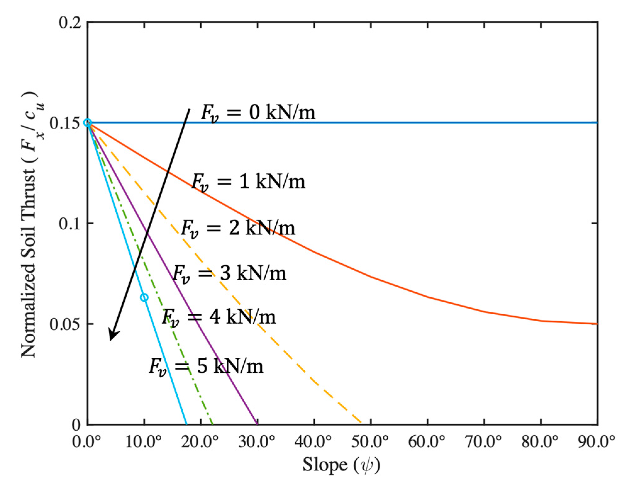
  • Block failure mode: The soil thrust decreases as the slope angle increases, provided that there is the weight of a vehicle. The critical weight of a vehicle associated with a single track can be also determined, which yields the condition where the soil thrust becomes zero under the given clay slope;
  • Triangular-wedge failure: The critical soil thrust depends on the vehicle weight and the slope angle. Overall, the soil thrust decreases as the slope angle decreases;
  • Trapezoidal-wedge failure: this failure mode cannot be established on a clay slope regardless of the inclination angle.
According to the upper-bound analysis, the geometry of a single-track system affects which failure mode can occur, i.e., either the block or the triangular-wedge failure mode. In addition, the soil thrust of each failure mode varies depending on the vehicle weight and the slope inclination angle; the soil thrust decreases as the slope becomes stiff and the vehicle weight increases under the block failure mode. On the other hand, the soil thrust decreases overall as the slope angle decreases under the triangular-wedge failure mode. It is worth noting that the proposed analytical solutions will require further experimental validation work with a variety of ground conditions and track system configurations.

Author Contributions

Conceptualization, S.N. and S.I.W.; methodology, S.H.N. and S.I.W.; formal analysis, S.N and S.I.W.; writing—original draft preparation, S.H.N.; writing—review and editing, S.H.N. and S.I.W.; visualization, S.N. All authors have read and agreed to the published version of the manuscript.

Funding

This work was supported by an INHA UNIVERSITY research grant. This research was also supported by Basic Research Project through the National Research Foundation of Korea funded by the Ministry of Science and ICT (NRF-2022R1F1A1074378).

Institutional Review Board Statement

Not applicable.

Informed Consent Statement

Not applicable.

Data Availability Statement

The data presented in this study are available on reasonable request from the corresponding author.

Acknowledgments

The first author gratefully acknowledges the financial support of INHA UNIVERSITY research grant. The corresponding author acknowledges the financial support by Basic Research Project through the National Research Foundation of Korea funded by the Ministry of Science and ICT (NRF-2022R1F1A1074378).

Conflicts of Interest

The authors declare no conflict of interest.

References

  1. Wong, J. An introduction to Terramechanics. J. Terramech. 1984, 21, 5–17. [Google Scholar] [CrossRef]
  2. Bekker, M.G. Mechanics of locomotion and lunar surface vehicle concepts. SAE Trans. 1964, 72, 549–569. [Google Scholar]
  3. Angelopoulos, V. The ARTEMIS Mission. Space Sci. Rev. 2011, 165, 3–25. [Google Scholar] [CrossRef]
  4. Oravec, H.A. Understanding Mechanical Behavior of Lunar Soils for the Study of Vehicle Mobility. Ph.D. Thesis, Case Western Reserve University, Cleveland, OH, USA, 2009. [Google Scholar]
  5. Asnani, V.; Delap, D.; Creager, C. The development of wheels for the lunar roving vehicle. J. Terramech. 2009, 43, 89–103. [Google Scholar] [CrossRef]
  6. Vu, M.T.; Choi, H.S.; Kim, J.Y.; Tran, N.H. A study on an underwater tracked vehicle with a ladder trencher. Ocean. Eng. 2016, 127, 90–102. [Google Scholar] [CrossRef]
  7. Baek, S.H.; Shin, G.B.; Chung, C.K. Experimental study on the soil thrust of underwater tracked vehicles moving on the clay seafloor. Appl. Ocean. Res. 2019, 86, 117–127. [Google Scholar] [CrossRef]
  8. Bekker, M.G. Theory of Land Locomotion; University of Michigan Press: Ann Arbor, MI, USA, 1956. [Google Scholar]
  9. Grečenko, A. Re-examined principles of thrust generation by a track on soft ground. J. Terramech. 2007, 44, 123–131. [Google Scholar] [CrossRef]
  10. Grečenko, A. Thrust and slip of a track determined by the compression–sliding approach. J. Terramech. 2007, 44, 451–459. [Google Scholar] [CrossRef]
  11. Park, W.; Lee, K.; Park, J. The prediction of side thrust generated by grousers under track. J. Korean Soc. Agric. Mach. 2000, 25, 1–10. [Google Scholar]
  12. Woo, S.I.; Baek, S.H. Upper-bound analysis for soil thrust of single-tracked system over clay ground. Int. J. Geomech. 2020, 20, 06019023. [Google Scholar] [CrossRef]
  13. Lvov, E.D. Theory of Tractor; Machgyz: Moscow, Russia, 1952. [Google Scholar]
  14. Park, Y. Interaction of Soils-Tracked Vehicle. Ph.D. Thesis, Seoul National University, Seoul, Republic of Korea, 1996. [Google Scholar]
  15. Asaf, Z.; Rubinstein, D.; Shmulevich, I. Evaluation of link-track performances using DEM. J. Terramech. 2006, 43, 141–161. [Google Scholar] [CrossRef]
  16. Yong, R.N.; Fattah, E.A.; Skiadas, N. Vehicle Traction Mechanics; Elsevier: Amsterdam, The Netherlands, 2012. [Google Scholar]
Figure 1. Illustration of a typical continuous-tracked vehicle, a single-track system, and a soil block on sloped ground with the angle ψ .
Applsci 13 05222 g001
Figure 2. Schematics of a soil block with a definition of its coordinate system, dimensions H , L , soil thrust F x , overburden force ( F v ), and inclination angle of slope ( ψ ).
Applsci 13 05222 g002
Figure 3. Block failure mode of a single-track system on clay slope. F x , F v , V , and ψ denote the soil thrust, overburden force transmitted from the weight of the vehicle, velocity, and slope angle, respectively.
Applsci 13 05222 g003
Figure 4. Variation in the soil thrust F x normalized by c u under the block failure mode with different slope angles ψ and weight of vehicle F v . The geometry of a soil block with H = 0.05 m and L = 0.15 m was adopted for the parametric study.
Applsci 13 05222 g004
Figure 5. Triangular- and trapezoidal-wedge failure modes of a single-track system on a clay slope. F x , F v , V , and ψ denote the soil thrust, overburden force transmitted from the weight of the vehicle, velocity, and slope angle, respectively. (a) Triangular-wedge failure mode: 0 < θ tan 1 L / H ; (b) Trapezoidal-wedge failure mode: tan 1 L / H < θ π / 2 .
Applsci 13 05222 g005
Figure 6. Variation in the soil thrust F x normalized by c u under a triangular-wedge failure mode with different slope angles ψ , failure wedge angles ( θ ), and weights of vehicles F v . The maximum θ value was approximately 71.65 ° with the geometry of a soil block with H = 0.05 m and L = 0.15 m. (a) F v = 0 , (b) F v = 5 kN/m, (c) F v = 10 kN/m, and (d) F v = 15 kN/m.
Applsci 13 05222 g006
Disclaimer/Publisher’s Note: The statements, opinions and data contained in all publications are solely those of the individual author(s) and contributor(s) and not of MDPI and/or the editor(s). MDPI and/or the editor(s) disclaim responsibility for any injury to people or property resulting from any ideas, methods, instructions or products referred to in the content.

