Article

Structure Optimization and Control Design of Electronic Oxygen Regulator

School of Mechanical and Electrical Engineering, Anhui Jianzhu University, Heifei 230009, China
*
Author to whom correspondence should be addressed.
Appl. Sci. 2023, 13(9), 5431; https://doi.org/10.3390/app13095431
Submission received: 31 March 2023 / Revised: 21 April 2023 / Accepted: 23 April 2023 / Published: 27 April 2023
(This article belongs to the Topic Designs and Drive Control of Electromechanical Machines)

Abstract

:
The oxygen regulator is the core component of the aircraft life support system, which adjusts the flow and pressure of the breathing gas according to the pilot’s breathing needs. In response to the problem that structural parameters are difficult to adjust and prone to jitter when the indirect oxygen regulator system is stable, a direct oxygen regulator is designed using a stepper motor to drive a lung-type flapper, replacing the diaphragm lever-type structure of the indirect oxygen regulator. Due to the nonlinearity and time-varying nature of the dynamic characteristics of oxygen regulators, a single-neuron PID control strategy based on online identification of RBF neural networks is proposed to improve the PID control performance. The RBF neural network is used to identify the Jacobian information of the controlled object, and the single-neuron PID controller completes the online adjustment of the controller parameters to realize the intelligent control of the system. Simulation experimental studies are conducted to verify the performance of the direct oxygen regulator. The result analysis verifies the excellence of the single-neuron PID control strategy based on online recognition of the RBF neural network to improve the system performance.

1. Introduction

With the development of onboard electronics, electronic oxygen supply regulators using electronic technology and sensor technology for control began to appear [1,2]. It is mainly through the pressure sensor that one can feel the small pressure difference, with the use of the solenoid valve to control the opening of the valve, or using the micro-motor-driven diaphragm to indirectly drive the opening of the oxygen supply valve to achieve oxygen supply regulation [3]. The performance of the electronic oxygen supply regulator has greatly improved, and it can adapt to the low outlet pressure of molecular sieve oxygen system and has the advantages of small size, light weight, high flow rate, low suction resistance, and fast dynamic response, which is the future development direction of airborne oxygen supply regulators [4,5,6].
At present, the actuator of the electronic oxygen regulator is mainly mechanical, and the control part adopts the electronic auxiliary regulation [7]. The system is dominated by mechanical actuator regulation and is supplemented by electronic regulation control to improve the comprehensive performance of the system, where the oxygen supply regulator and anti-charge regulator are integrated into a system, which compared to the mechanical control system performance makes it a great improvement [8]. This indirect oxygen regulator indirectly controls the opening and closing of the pulmonary oxygen supply valve by controlling the residual pressure valve with a motor. However, there are still disadvantages in that the mechanical oxygen regulator mechanism parameters are difficult to adjust, and the pressure is easy to fluctuate.
In the research on oxygen regulator structures, Wan et al. studied the calculation of the structural parameters of an indirect oxygen regulator [9]. The performance parameters of the indirect oxygen regulator were analyzed by Zou et al. [10]. Concerning the electronic control of oxygen regulators, Yu et al. used switching control [11] and Sun et al. applied fuzzy control to design a control law for an electronic oxygen regulator [12]. Li et al. used expert control to automatically adjust the PID parameters, which solved the deficiency of fixed control parameters [5]. Jiang et al. pointed out that disturbance suppression is a key issue in the control of oxygen regulators. Generalized predictive control (GPC) [13], automatic disturbance rejection control (ADRC) [14], and the adaptability has been applied to controllers to improve performance [15].
In the control application of an oxygen regulator, there are unknown perturbations acting on the system such as gas source pressure changes and suction flow changes in the oxygen regulator, and it is difficult to achieve the desired control effect with a fixed parameter PID regulator. Therefore, the control method of a single-neuron PID is adopted, and an RBF neural network is introduced for online identification of system output to provide system dynamic information for the learning process of single-neuron PID.
Through the study and analysis of an indirect oxygen regulator, it is found that the parameters of the indirect oxygen regulator are not easily adjustable, and they jointly affect the overall performance. It is necessary to optimize the structure of the indirect oxygen regulator by changing the parameters and proposing a direct oxygen regulator to solve the jitter problem caused by the diaphragm lever mechanism. An intelligent control method is applied to improve the breathing resistance and pressure fluctuation of the oxygen regulator. This paper designs a direct oxygen regulator structure based on the indirect oxygen regulator by merging the lung type valve mechanism and the electronically controlled residual pressure valve mechanism of the indirect electronic oxygen regulator, and optimizing it to a direct motor-driven valve mechanism to close or open the valve for oxygen supply and establish a mathematical model of respiratory pressure control. In this control system structure, the RBF neural network is used to identify the Jacobian information of the controlled object and the online adjustment of the controller parameters is completed by the single-neuron PID controller to realize the intelligent control of the system. The control performance of the structure’s design and control method on pressure fluctuation and breathing resistance is verified through a simulation and experiment.

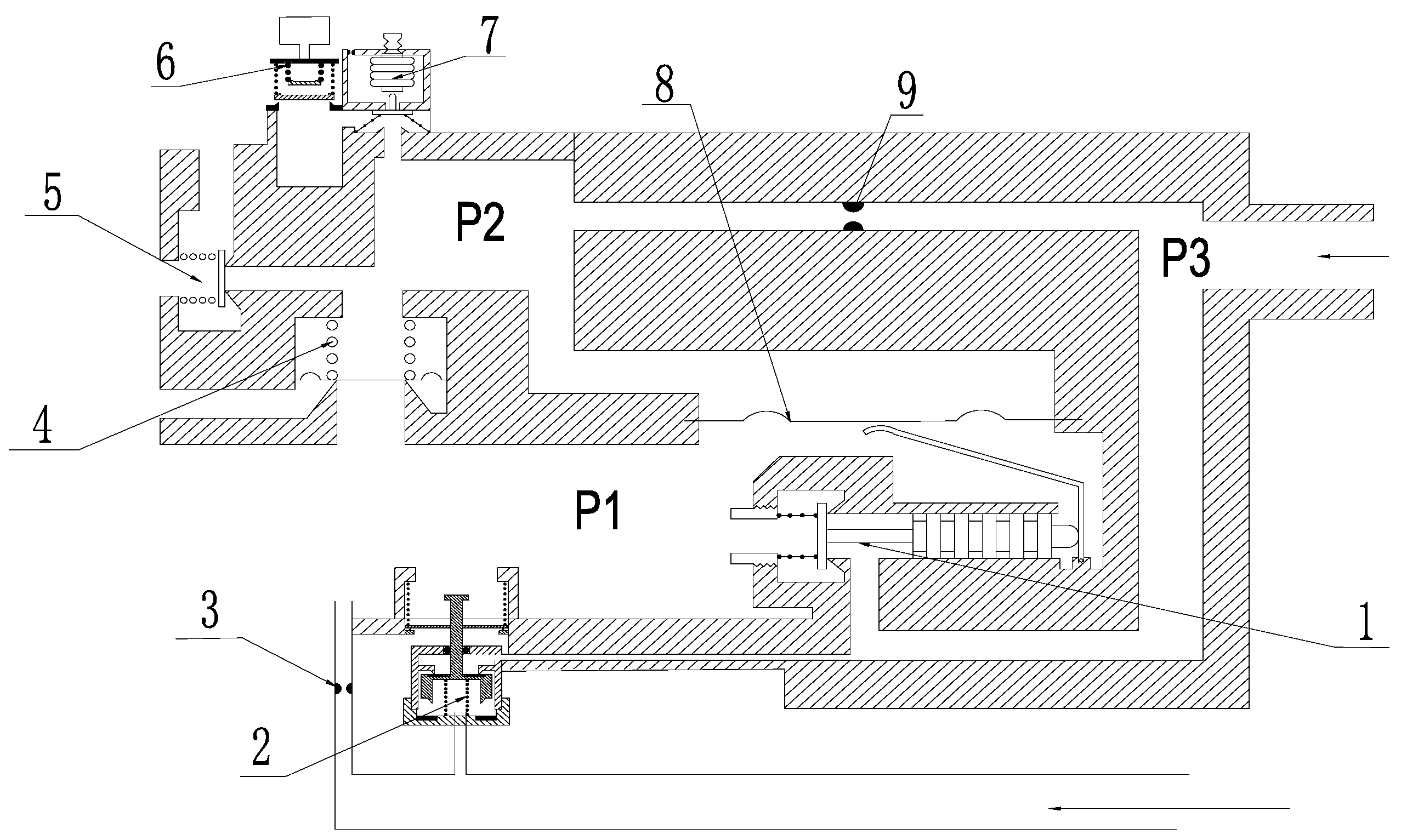
2. Oxygen Regulator Principle Analysis

2.1. Indirect Oxygen Regulator Principle

Combined with the structure principle of indirect oxygen regulator in Figure 1, when the pilot inhales, the P2 pressure measurement point detects the negative pressure generated by the pilot’s inhalation, and the electronic control device controls the electronically controlled residual pressure valve to move forward to establish the residual pressure chamber pressure (P2 pressure measurement point); the residual pressure chamber pressure acts on the main lung valve diaphragm, which deforms the main lung valve diaphragm to open the main valve to supply air to the pilot. When the pilot exhales, P1 detects the exhalation action, and the electronic control device controls the electronically controlled residual pressure valve to move backward and remove the residual pressure chamber pressure, and the main lung valve diaphragm returns to its initial state to close the main valve and stop supplying air to the pilot. When the height rises, the electronic control device controls the electronically controlled residual pressure valve to move forward and establish the safety residual pressure (P2 pressure measurement point). The breathing chamber pressure is controlled by the residual pressure chamber pressure through the main lung type valve diaphragm 8 and the main valve to establish the safety residual pressure.

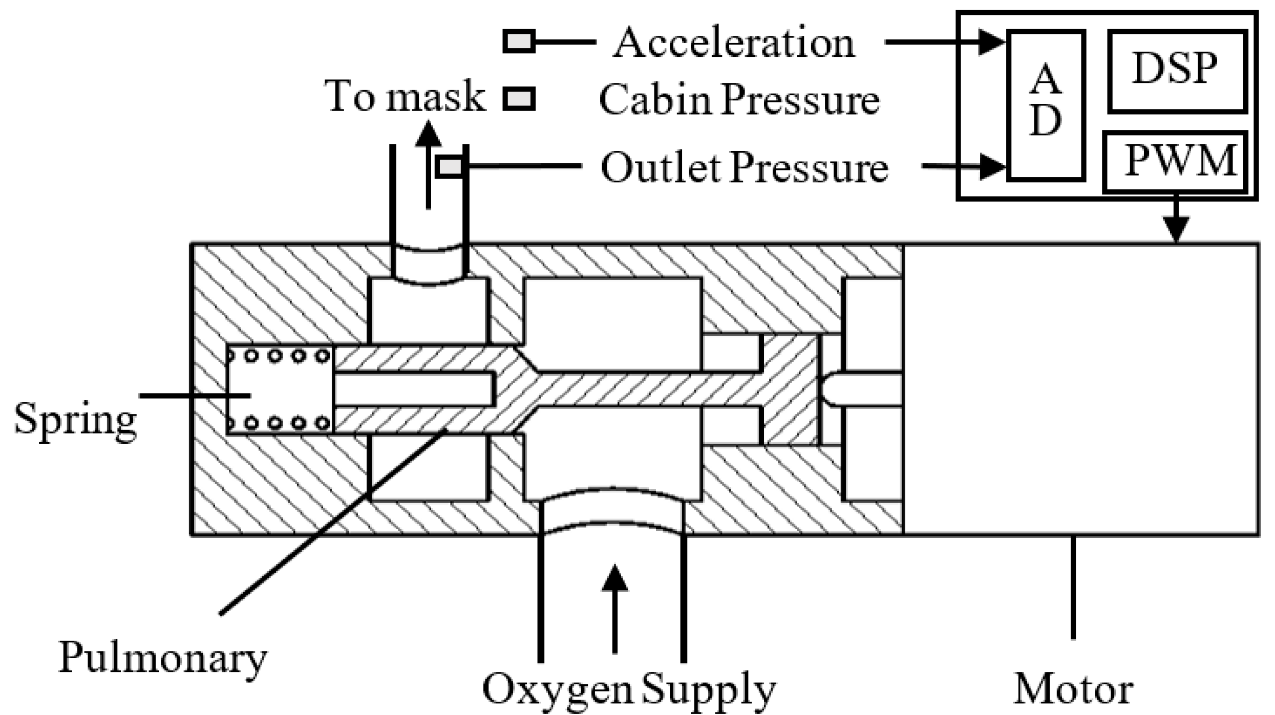
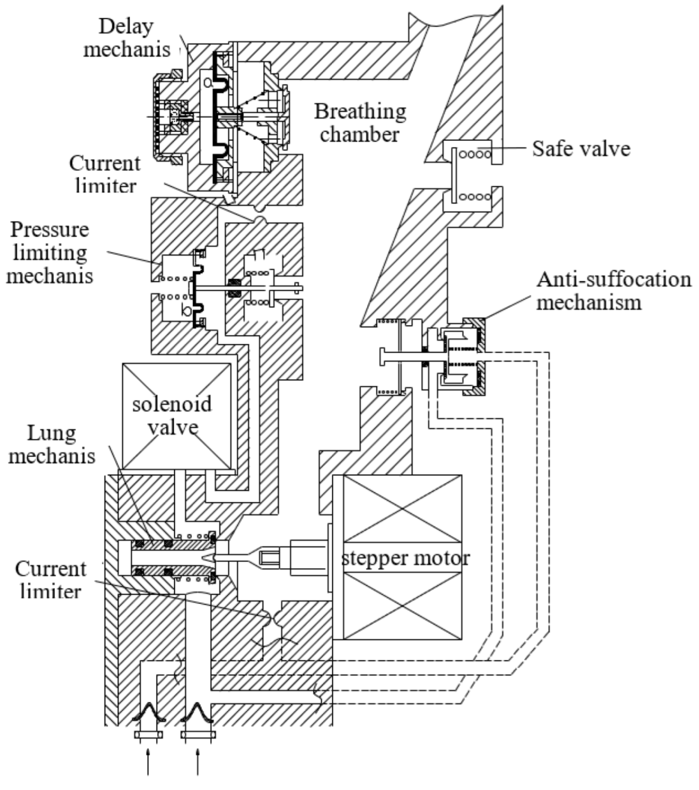
2.2. Optimized Design

The literature [15] proposes that the phenomenon of positive pressure fluctuations is caused by a combination of inlet pressure fluctuations and diaphragm deformation. At low lung flux, the effects of both causes are similar. At high lung flux, diaphragm deformation becomes the main cause of significant positive pressure fluctuations.
To address this one drawback of the indirect oxygen regulator, a structural solution design was focused on the oxygen supply assembly. The lung-type flapper mechanism and the electronically controlled residual pressure flapper mechanism of the indirect electronic oxygen supply anti-charge regulator are combined and optimized to close or open the flapper for oxygen supply by direct motor drive. The design of removing the diaphragm can fundamentally improve the system performance of the oxygen regulator.
The stepper motor is driven to open or close the oxygen supply door of the lung mechanism according to the parameters of cockpit height, acceleration, and product input and output pressure collected by the sensor set. The opening and closing of the oxygen supply door of the lung mechanism is realized by the electronic control device. The schematic sketch of the pulmonary mechanism is shown in Figure 2. The flow restrictor provides a continuous flow of oxygen supply. When the control or power failure occurs in the electronically controlled oxygen supply, and normal oxygen supply cannot be carried out, oxygen regulation must be implemented to downgrade the oxygen supply. When a power failure occurs or the electronic control device monitors the abnormal output of the subsystem, the electronic control device drives the normally open solenoid valve down to turn on the continuous flow and implement the downgraded oxygen supply. The oxygen supply assembly mainly consists of a shell assembly, a linear stepping motor, a normally open solenoid valve, a lung mechanism, a flow limiter, a time delay mechanism, a safety valve mechanism, an anti-asphyxiation mechanism, and a pressure limiting mechanism. The structure’s schematic diagrams are shown in Figure 2 and Figure 3, respectively.

3. Control Method Design

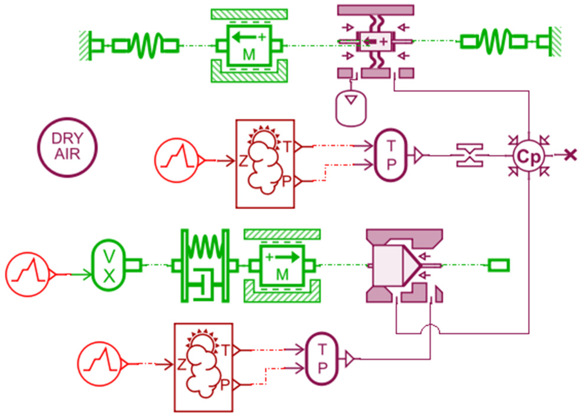
3.1. Mathematical Modeling

The mathematical model of the oxygen regulator consists of two parts: the pulmonary valve and the stepper motor. Due to the complex structure of the entire oxygen regulator, model identification using system identification techniques is very difficult. Combining the advantages of identification techniques and mechanistic analysis, both the lung valve and stepper motor models are based on mechanistic analysis.
Before building the mathematical model, it can be assumed that the gas is regarded as an ideal gas and satisfies the ideal gas equation [16]. The process of gas flow through the positive pressure chamber and the valve is very short, so the heat exchange can be neglected and the gas flow state is regarded as an isentropic process [15]. Considering the gas in the suction chamber as a control body, the dynamic equations of the gas pressure and flow in the suction chamber are as follows:
d p d t = K · R g · T · δ m V
δ m = G i n G o u t
where p is the gas pressure in the suction chamber, T is the gas temperature, K is the gas adiabatic index, R g is the gas constant, V is the volume of the suction chamber, δ m is the mass change, G i n is the gas mass flow rate into the suction chamber, and G o u t is the gas mass flow rate out of the suction chamber.
The gas flow area of the valve is calculated as follows:
A = π · d x sin θ cos θ x · sin θ
where d is the diameter of the valve hole, θ is the valve half taper, and x is the valve opening.
The gas flow in the suction chamber can be considered an isentropic flow [16]. When expressing the gas mass flow equation, there are two cases.
In the first case, when p / p i n > ε
G i n = C d · A · p i n R g · T i n 2 κ K 1 p p i n 2 κ 1 p p i n κ κ 1
In the second case, when p / p i n ε
G i n = C d · A · p i n · B R g · T i n 2 κ κ + 1 2 κ + 1 2 κ 1
where C d is the flow coefficient of the flapper, A is the flow area of the flapper, ε = 2 κ + 1 κ κ 1 is the critical pressure ratio, p i n is the inlet gas pressure, and T i n is the inlet gas temperature.
The following force balance equation is satisfied during the motion of the stepper motor:
m d 2 x d t = F m c d x d t k x + F d
F m = k m · i
where m is the mass of the moving part, F m is the electromagnetic force, c is the viscous damping factor, k is the spring stiffness, and F d is the disturbance force, i is the coil current, and k m is the electromagnetic force coefficient.
The mathematical model can be synthesized as follows:
p ˙ = f 1 p , w 1 + b 1 x x ¨ = f 2 x , x ˙ , w 2 + b 2 u y = p
where w 1 and w 2 are unknown perturbations.
f 1 p , w 1 = κ · R g · T V k 1 p G o u t
f 2 x , x ˙ , w 2 = c m + k m k E m R x ˙ k m x + F d m
b 1 = κ · R g · T V k 2
b 2 = k m m R
In the simulation calculation, G o u t is calculated by the human lung capacity model. The variation of human lung capacity can be regarded as a sinusoidal law variation.

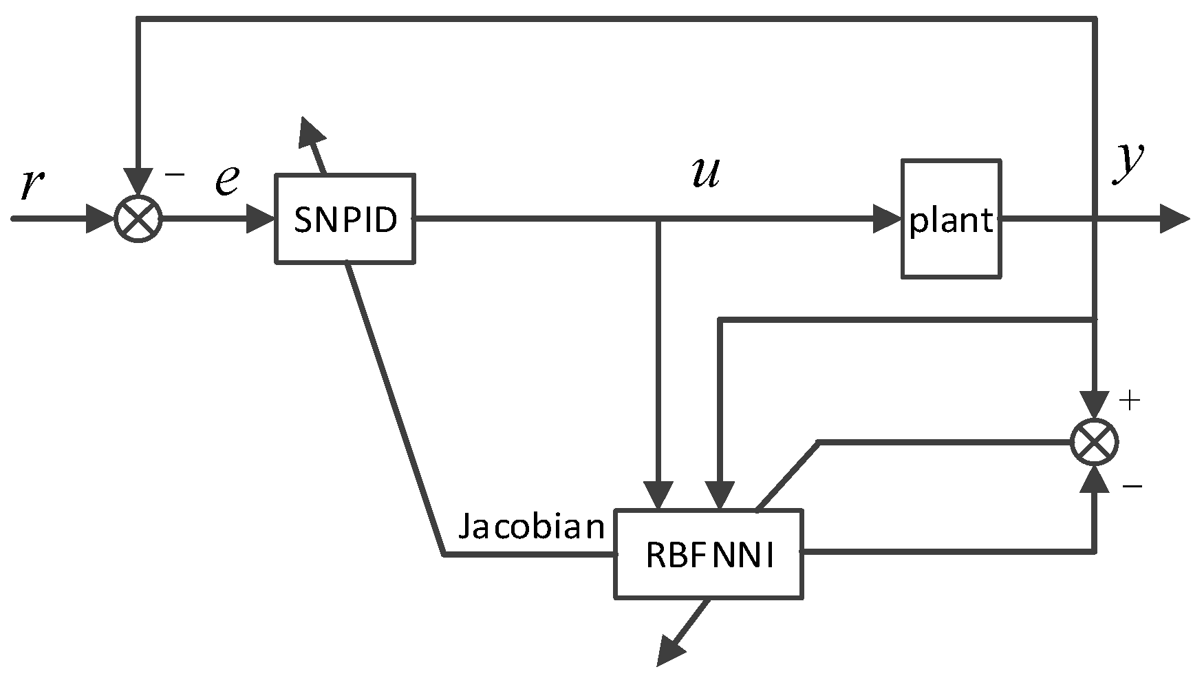
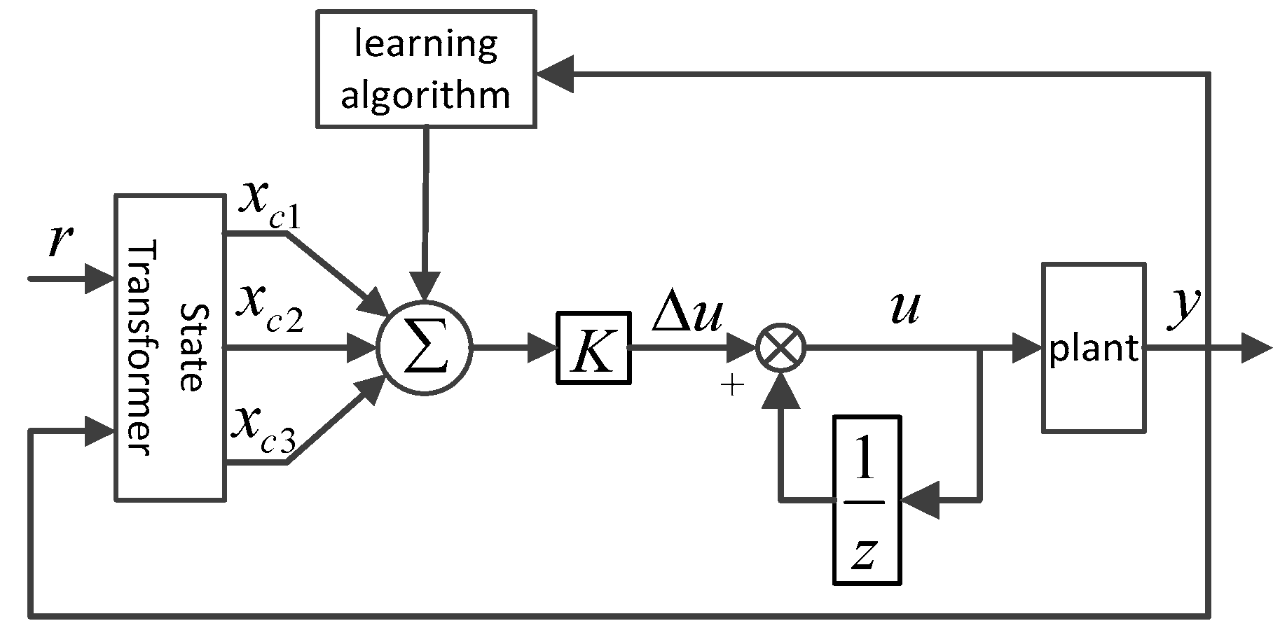
3.2. Controller Design

According to the oxygen regulation principle of the direct oxygen regulator, the electronic control device drives the stepper motor to open or close the oxygen supply valve of the pulmonary mechanism according to parameters such as cockpit height, acceleration, and product input and output pressure collected by the sensor group. The goal of the controller design is, on the one hand, to regulate u to keep the output pressure y close to a given reference input; on the other hand, to regulate u to counteract the effects of various disturbances w. In both cases, the smaller the control error e = ry, the smaller the suction resistance and pressure fluctuations. During the operation of the oxygen regulator, the output gas pressure was affected by various disturbances such as pilot suction flow, change in gas source pressure, a disturbance force acting on the flapper, change in motor parameters, etc. The structural parameters of the whole control system are time-varying and non-linear, and the PID regulator with fixed parameters cannot get the ideal control quality. A single-neuron PID control method is used, and an RBF neural network is introduced for online identification of the system output to provide system dynamic information for the learning process of the single-neuron PID [17]. The control system structure is shown in Figure 4. In Figure 4, SNPID is the single-neuron PID controller and RBFNNI is the RBF neural network discriminator.
An adaptive single-neuron PID control method based on dynamic RBF neural network identification is proposed in the reference paper [18], where a dynamic neural network identifier identifies the system model online, obtains online tuning information of the PID parameters, and the single-neuron controller realizes the self-tuning of the controller parameters. The system has the advantages of high adaptability and robustness compared with the traditional RBF neural network-based PID control method. The single-neuron PID controller based on RBF neural network recognition consists of a single-neuron PID controller and a dynamic RBF neural network recognizer. The dynamic RBF neural network is used to model the system, obtain a predictive mathematical model of the system, replace the actual output of the object with the predicted output of the model, and then design the single-neuron PID controller. The network recognition structure adopts a series-parallel structure to ensure the stability of the system.
The single-neuron PID controller is a controller that combines PID control laws and neural networks [19], and the implicit layer contains three units that are proportional (P), integral (I), and differential (D), and the structure of this controller is shown in Figure 5. Adaptivity is achieved through the adjustment of single-neuron weighting coefficients and the commonly used learning rules are the unsupervised Hebb learning rule, supervised Delta learning rule, and supervised Hebb learning rule [19]. In this paper, the controller performs online rectification of the weights based on the gradient descent method and the Jacobian information provided by the RBFNNI. The control and learning algorithms are as follows:
Let the system control error be e(k) = r(k)y(k). Take the neuron input as:
x c 1 k = e k e k 1 x c 2 k = e k x c 3 k = e k 2 e k 1 + e k 2
Neuronal outputs are:
u k = u k 1 + K i = 1 3 v i k x c i k
where v i k is the weight coefficient of a single-neuron network, and K > 0 is the scale factor of single neuron. The performance index function of the controller was taken as:
J c = 1 2 e 2 k
According to the gradient descent method, the adjustment of the single-neuron weighting coefficient is:
v i k + 1 = η i J c v i k = η i J c y y u u v i k = η i e k y u K x c i k
where n is the learning rate and y can be replaced by the RBFNN discrimination information u. From this, the adjusted weighting coefficient was obtained as:
v i k + 1 = v i k + v i k + 1
To ensure the convergence and robustness of the control algorithm Equations (16) and (17), the learning algorithm was normalized [20] to obtain:
u k = u k 1 + K i = 1 3 v i k x c i k v i k = v i k / i = 1 3 v i k

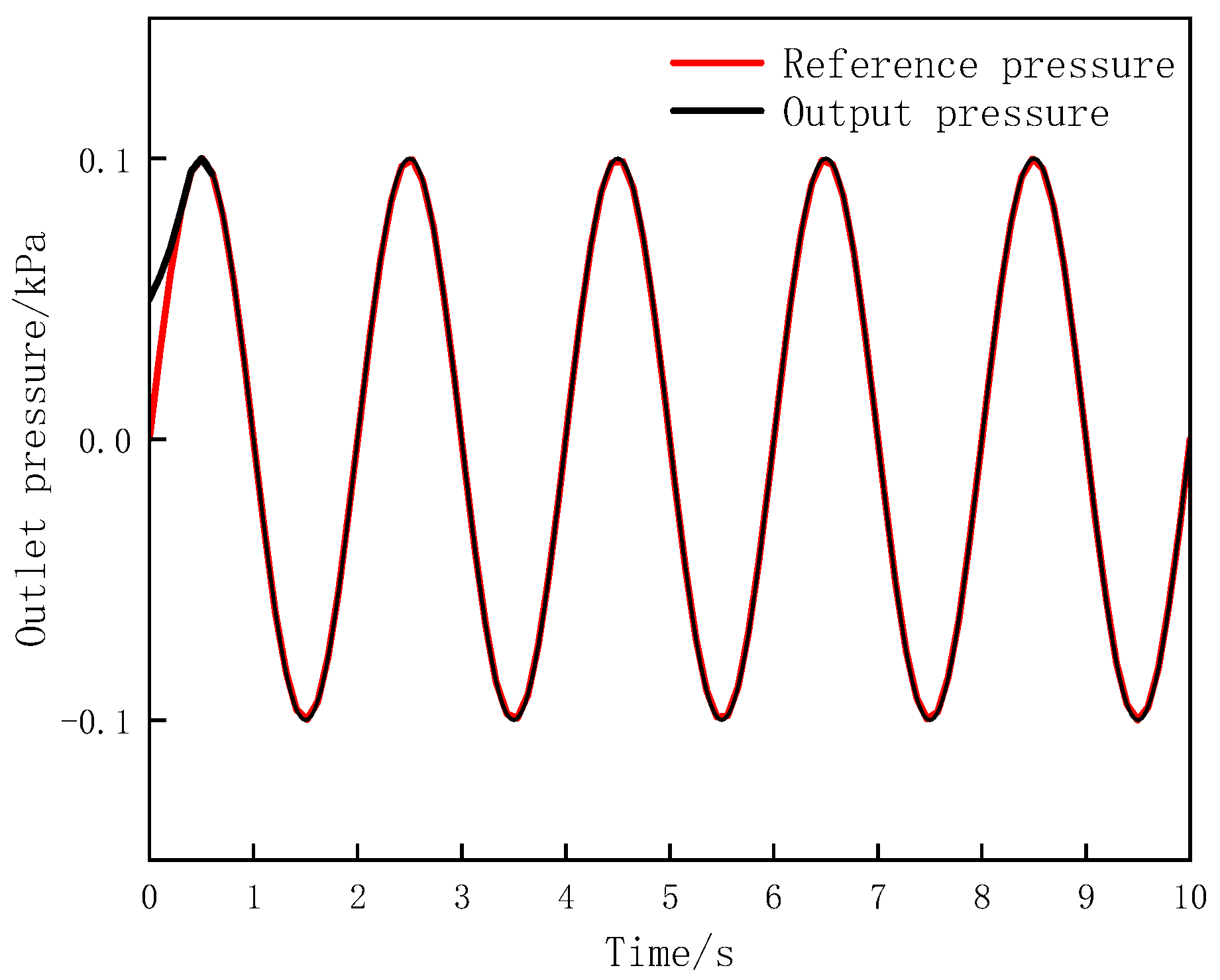
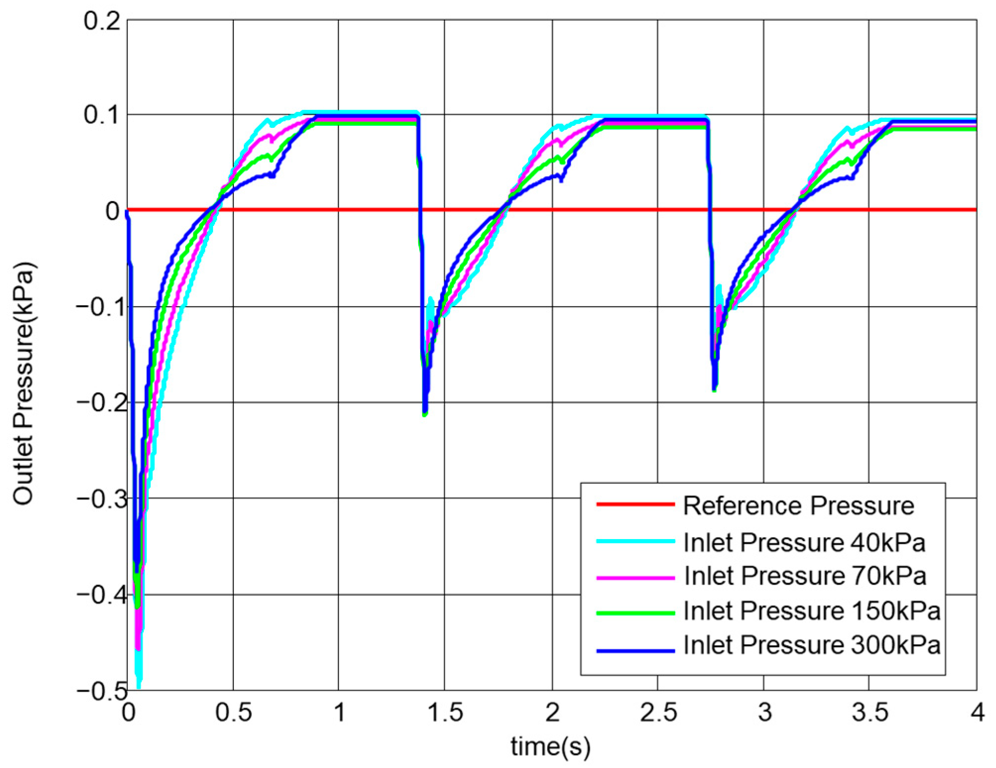
3.3. Simulation Results

For the structural characteristics of the direct oxygen regulator, the performance of the direct oxygen regulator is analyzed by a simulation focusing on the pulmonary mechanism and pressure limiting mechanism, and the simulation structure is represented in Figure 6. The respiratory flow rate of the user varies approximately according to the sinusoidal law. A joint simulation of the model was implemented using amsim and simulink. The sampling time is 0.001 s. The parameters used in the simulation and their values are listed in Table 1.
Oxygen supply is mainly achieved by stepper motors opening or closing the oxygen supply valve of the pulmonary mechanism. The simulation structure includes only the motor and its driven lung mechanism, the pressure limiting mechanism, and the breathing chamber. The principle of the pulmonary mechanism is mainly a motor pushing the pulmonary valve, and the simplified simulation mechanism is represented in Figure 6. The pressure profile of the output respiratory chamber fluctuates after a given respiratory pressure profile.
It can be seen in Figure 7 that the pressure in the breathing chamber is essentially consistent with the reference pressure and that it follows this well.
Combined with the single-neuron PID control strategy based on online identification of the RBF neural network, the sampling time in the simulation is 0.001 s and the main parameters are shown in Table 2. The network structure of the RBFNNI is 3-6-1, and the network input is x = [u(k) y(k) y(k − 1)], η = 0.2, α = 0.05. SNPID in taking K = 6,   η 1 = 0.2 ,   η 2 = 0.001 ,   a n d   η 3 = 0.1 .
At a lung ventilation rate of 44 L/min and inlet gas pressures of 40 kPa, 70 kPa, 150 kPa, and 300 kPa, the oxygen regulator outlet pressure curve is shown in Figure 8.
The reference pressure is used as both the regulation target value and the dividing line of respiratory resistance. An outlet pressure value above the reference pressure indicates expiratory resistance and an outlet pressure value below the reference pressure indicates inspiratory resistance. After entering the respiratory cycle, the desired outlet pressure should converge to the reference pressure. The peak pressure fluctuations in Figure 8 are between 0.1 kPa and −0.2 kPa. Near the positive and negative peak pressures, the outlet pressure is essentially the same; at the respiratory pressure transition, with an inlet pressure of 300 kPa, the regulator output pressure converges more closely to the reference pressure. Changes in the regulator’s inlet gas pressure have little effect on the output pressure, and the oxygen regulator is able to output a stable pressure. When the inlet gas pressure is higher, the regulator output pressure is closer to the reference pressure.

4. Experimental Analysis

The electronic oxygen regulator designed in this paper was tested under ground test chamber conditions using mechanical lungs for pressurization, with industrial oxygen as the gas source and a pressurized oxygen supply mask for simulation experiments.

4.1. Experimental Projects

The indirect oxygen regulator was compared with the designed direct oxygen regulator for the experiment.
  • Breathing resistance test
The flow characteristics of the oxygen regulator are mainly ensured by the pulmonary mechanism, and the suction resistance is the main characteristic of this mechanism. To verify the flow characteristics of the direct oxygen regulator, a breathing resistance experiment was designed. Respiratory resistance tests were performed on mechanical lungs with lung ventilation volumes of 20 L/min, 30 L/min, and 44 L/min at an inlet gas pressure setting of 150 kPa, and the pressure fluctuations in the mask chamber were measured. As shown in Figure 9, piece 4 should be connected to piece 5; piece 12 should be opened, the breathing gas resistance test mode should be selected; switch 1 should be turned on, the pressure reducer 2 should be turned on; the pressure reducer 2 should be turned on according to the pressure gauge 3 to establish the pressure of 150 kPa; the dummy lung 9 should open in order to establish a 20 L/min, a 30 L/min, and a 44 L/min lung gas exchange volume; the value of the pressure gauge 11 should be recorded.
2.
Pressurization test
In high-altitude and overload situations, a certain amount of positive pressure needs to be established in the oxygen supply mask through active control based on the altitude and overload values to achieve pressurized respiratory protection and to improve the pilot’s tolerance in high-altitude and overload environments. Calculate the target pressure according to the cockpit height and control and adjust the target pressure of the oxygen supply. The cockpit height is expressed by atmospheric pressure, and the relationship between the oxygen supply target pressure and the cockpit height is shown in Figure 10 [21]. When the cockpit altitude PH < 16.5 kPa, the target pressure value of the oxygen supply is shown in the equation.
P B = 0.756 P H + 14.14
When the oxygen supply regulator works in pressurized breathing regulation, it needs to pressurize the mask chamber at 2.0 kPa, 5.0 kPa, 7.5 kPa, and 8.5 kPa, as well as measure the pressure value of the mask chamber. It should connect according to Figure 10; connect piece 4 to piece 6, turn on switch 1, turn on pressure reducer 2 to establish a pressure of 2 kPa according to the pressure gauge 3; turn on switch 1, turn on pressure reducer 2 to establish a pressure of 0.2 MPa according to the pressure gauge 3; turn on switch 15 and slowly rise to 16 kPa according to the pressure gauge 14; record the residual pressure establishment height and residual pressure value.

4.2. Analysis of Experimental Results

The pressure profiles of the mask chamber at different lung fluxes at an inlet gas pressure of 150 kPa are shown in Figure 11. The positive peak of the waveform indicates the maximum expiratory pressure, and the negative peak indicates the inspiratory pressure [17]. At a lung ventilation volume of 20 L/min, the maximum inspiratory resistance was 0.25 kPa and the maximum expiratory resistance was 0.1 kPa. At a lung ventilation rate of 30 L/min, the maximum inspiratory resistance was 0.27 kPa and the maximum expiratory resistance was 0.13 kPa. At a lung ventilation rate of 44 L/min, the maximum inspiratory resistance was 0.4 kPa and the maximum expiratory resistance was 0.25 kPa. Comparing the appeal data with the ideal boundary values of respiratory resistance in Table 3, the peak resistance was all within the ideal boundary and much smaller than the boundary of respiratory resistance [22].
The experimental data on the respiratory resistance of the indirect electronic oxygen supply anti-charge regulator are shown in Table 4. In comparison with the indirect oxygen regulator, it can be seen that the output of the direct oxygen regulator has less breathing resistance, which greatly enhances the comfort of the pilot when in use.
When the oxygen supply regulator was used for pressurized breathing, the target pressure values of the pressurization test were 2.0 kPa, 5.0 kPa, 7.5 kPa, and 8.5 kPa, respectively. The pressure curves of the mask cavity are shown in Figure 12a,b.
During pressurization at 2.0 kPa, the pressure values can reached the target values at 0.4 s. When the pressurization value was at 8.5 kPa, the pressure value reached the stable target value at 0.6 s. The pressurization test process of the electronic oxygen regulator builds pressure quickly at different pressure targets. The speed of pressure building was within 0.8 s for all the different pressure tests. The smaller the target pressure of the pressurization test, the faster the pressure-building speed. For example, during the pressurization process at 2.0 kPa, the pressure value can reach the target value in 0.4 s. After the indirect oxygen regulator reaches the regulated pressure, there is a significant pressure fluctuation. However, indirect oxygen regulators have a longer pressure build-up time and exhibit significant pressure fluctuations.
The direct oxygen regulator solves the problem of pressure fluctuation of the indirect oxygen regulator, and the single-neuron PID control strategy based on online recognition of the RBF neural network improves the system performance, resulting in less breathing resistance and faster pressure building during pressurized breathing with the direct oxygen regulator.

5. Conclusions

In this paper, a direct oxygen regulator is designed for the problems of jittering output pressure and the difficult adjustment of structural parameters of an indirect oxygen regulator, and a stepper motor was used to drive the lung type valve, replacing the diaphragm lever-type structure of traditional indirect oxygen regulator.
A direct oxygen regulator with a single-neuron PID control strategy based on online recognition of the RBF neural network is designed by combining the current advanced intelligent control theory. The simulation results show that the control strategy makes the oxygen regulator have better control accuracy and system response speed.
The control performance of the oxygen regulator was verified experimentally. This control method reduces respiratory resistance by 50% and improves respiratory comfort compared to indirect oxygen regulators at different lung fluxes. In pressurized breathing, the output pressure fluctuation does not exceed 0.1kPa and the pressure build-up time is within 0.6 s, both of which show better performance than the indirect oxygenator regulator.

Author Contributions

Conceptualization, D.J. and Y.L.; methodology, D.J.; software, Y.L. and H.Y.; validation, Y.L., X.F. and B.Q.; investigation, H.L.; resources, D.J.; writing—original draft preparation, Y.L.; writing—review and editing, D.J.; All authors have read and agreed to the published version of the manuscript.

Funding

This research was funded by the Anhui Provincial University Natural Science Research Project (K2210033) and the Provincial Natural Science Research Projects of Anhui Provincial Universities (KJ2021A0635).

Institutional Review Board Statement

Not applicable.

Informed Consent Statement

Not applicable.

Data Availability Statement

The data is available from the corresponding author upon reasonable request.

Conflicts of Interest

The authors declare no conflict of interest.

References

  1. Fan, Y.; Sun, Q.; Dong, F.; Chen, Q. An adaptive oxygen regulator control system based on particle swarm optimization and back propagation neural network. Control Theory Appl. 2020, 3, 687–695. [Google Scholar]
  2. Siska, W.D., Jr.; Robert, C. Electromechanical Oxygen Valve and Regulator. U.S. Patent No. 7,677,529, 16 March 2021. [Google Scholar]
  3. Yan, S.H.I.; Yixuan, W.A.N.G.; Maolin, C.A.I.; Zhang, B.; Jian, Z.H.U. An aviation oxygen supply system based on a mechanical ventilation model. Chin. J. Aeronaut. 2018, 31, 197–204. [Google Scholar]
  4. Jiang, D.; Bu, X.; Lin, G.; Sun, B.; Huang, J.; Fang, L.; Zhao, H. Control design and experimental verification of three-bed airborne oxygen generation system. J. Beijing Univ. Aeronaut. Astronaut. 2018, 44, 6. [Google Scholar]
  5. Li, X.; Lin, G.; Zeng, Y.; Wu, F. Design of electronic oxygen regulator PID control system based on LabVIEW. Comput. Meas. Control 2016, 3, 80–83. [Google Scholar]
  6. Jiang, Y.; Sun, Q.; Tan, P.; Chen, Z. Modeling and Simulation of an Electronic Oxygen Regulator Based on All-Coefficient Adaptive Control. J. Dyn. Syst. Meas. Control 2016, 138, 081010. [Google Scholar] [CrossRef]
  7. Yuxin, J.; Qinglin, S.; Zengqiang, C.; Sanpeng, D. Modeling and simulation of an electronic oxygen regulator based on generalized predictive control algorithm. In Proceedings of the 2015 34th Chinese Control Conference (CCC), Hangzhou, China, 28–30July 2015; IEEE: Piscataway, NJ, USA, 2015; pp. 4067–4072. [Google Scholar]
  8. Jiang, D.; Jin, H.; Sun, B.; Lin, G.; Bu, X.; Zhao, H. Design and experiment research of pressure control cavity on electronic oxygen regulator. In Proceedings of the 2017 8th International Conference on Mechanical and Aerospace Engineering (ICMAE), Prague, Czech Republic, 22–25 July 2017; IEEE: Piscataway, NJ, USA, 2017; pp. 656–660. [Google Scholar]
  9. Wan, Y.; Zhao, J.; Zeng, Y. Design and calculation of structural parameters of aviation oxygen regulator. J. Beijing Univ. Aeronaut. Astronaut. 2011, 37, 351–354. [Google Scholar]
  10. Zou, N.; Zhang, B.; Wang, D.; Xiao, H.; Liu, X.; Zang, B. Performance parameter adjustment analysis and experimental verification of YTQ-7 oxygen regulator. Aerosp. Sci. Technol. 2011, 5, 45–48. [Google Scholar]
  11. Yu, X.; Sun, B.; Lin, G.; Wang, H. The application of ATmega128 single chip microcomputer in electronic oxygen regulator. Microcomput. Appl. 2009, 12, 50–56. [Google Scholar]
  12. Sun, C.; Cai, Y.; Long, H. Research on stepping motor fuzzy control technology application in the aircraft electronic oxygen regulator. Meas. Control Technol. 2013, 32, 78–81. [Google Scholar]
  13. Jiang, Y.; Sun, Q.; Zhang, X.; Chen, Z. Pressure regulation for oxygen mask based on active disturbance rejection control. IEEE Trans. Ind. Electron. 2017, 64, 6402–6411. [Google Scholar] [CrossRef]
  14. Morris-ward, M. Modification of Oxygen Regulator Functionality Tester for X-59 Regulator Testing. In Student Poster Day; NTRS—NASA Technical Reports Server: Washington, DC, USA, 2020. [Google Scholar]
  15. Pan, R.; Lin, G.; Shi, Z.; Zeng, Y.; Yang, X. Analysis and control optimization of positive pressure fluctuation in electromechanical oxygen regulator. Chin. J. Aeronaut. 2021, 34, 205–213. [Google Scholar] [CrossRef]
  16. Saha, B.K.; Songjing, L.I.; Xinbei, L.V. Analysis of pressure characteristics under laminar and turbulent flow states inside the pilot stage of a deflection flapper servo-valve: Mathematical modeling with CFD study and experimental validation. Chin. J. Aeronaut. 2020, 33, 1107–1118. [Google Scholar] [CrossRef]
  17. Pan, R.; Lin, G.; Shi, Z.; Zeng, Y.; Yang, X. The application of disturbance-observer-based control in breath pressure control of aviation electronic oxygen regulator. Energies 2021, 14, 5189. [Google Scholar] [CrossRef]
  18. Yinhu, L.; Shaoming, L. Single neuron PID control based on dynamic RBF neural network on-line identification. J. Syst. Simul. 2006, 18 (Suppl. 2), 804–807. [Google Scholar]
  19. Zhang, S.T.; Yang, F.; Hao, Q. Research and simulation of single neuron PID controller. Mech. Eng. Autom. 2009, 39, 69–70. [Google Scholar]
  20. Wang, N.; Tu, J.; Chen, J. Intelligent control using a single adaptive neuron. In Proceedings of the Third Congress of Chinese Association of Automation, Beijing, China; 1991; pp. 173–177. [Google Scholar]
  21. Liu, X.; Xiao, H.; Shi, Q. Evaluation of hypobaric chamber physiological test of YX-11 oxygen supply system. Chin. J. Aerosp. Med. 2007, 18, 20–25. [Google Scholar]
  22. Xiao, H. Review and Prospect of Physiological Research on Aviation Oxygen Supply Equipment. In Proceedings of the Academic Conference on Environmental Control and Ergonomics of Chinese Aviation Society, Beijing, China; 2000. [Google Scholar]
Figure 1. Indirect oxygen regulator structure schematic. P1: breathing chamber pressure measuring point; P2: residual pressure chamber pressure measuring point; P3: inlet pressure measuring point; 1: pulmonary valve; 2: air valve; 3: limiting hole; 4: ventilation valve; 5: safety valve; 6: residual pressure valve; 7: high residual pressure valve; 8: membrane; 9: sizing hole.
Applsci 13 05431 g001
Figure 2. Electronic oxygen regulator working principle diagram.
Applsci 13 05431 g002
Figure 3. Direct oxygen regulator structure schematic.
Applsci 13 05431 g003
Figure 4. Structure of a single-neuron PID control system based on RBF identification.
Applsci 13 05431 g004
Figure 5. Single-neuron controller structure.
Applsci 13 05431 g005
Figure 6. Oxygen regulator simulation structure.
Applsci 13 05431 g006
Figure 7. Respiratory chamber outlet pressure curve.
Applsci 13 05431 g007
Figure 8. Outlet pressure curve of the regulator with 44L/min ventilation.
Applsci 13 05431 g008
Figure 9. Experimental equipment connection diagram. 1: high pressure switch; 2: reducer adjustable; 3: pressure gauge; 4: connector; 5: anti-load inlet; 6: main oxygen inlet; 7: regulator; 8: tooling for simulating gas source distributor; 9: vacuum box; 10: mask model; 11: oil pressure gauge; 12: exciter; 13: height sensor; 14: altimeter; 15: vacuum switch; 16: deflation switch; 17: pressure gauge; 18: connector; 19: reducer adjustable; 20: high pressure switch.
Applsci 13 05431 g009
Figure 10. Relationship between cockpit height and oxygen supply target pressure curve.
Applsci 13 05431 g010
Figure 11. Mask pressure curves under different lung fluxes.
Applsci 13 05431 g011
Figure 12. (a) Pressure curve of the mask chamber during pressurization; (b) indirect oxygen regulator mask chamber pressure.
Applsci 13 05431 g012
Table 1. Structural parameters.
ParameterValue
Spring stiffness (N/m)470
Volume of chamber (cm3)13
Diameter of hole (mm)10
Diameter of poppet (mm)15
Orifice area (mm2)0.1
Table 2. Main parameters in the simulation.
Parameter (Unit)Value
m (kg)0.037
K (N/m)700
d (m)0.07
Θ (º)11
R (Ω)15
Km (N/A)23
KE (V/(m/s))23
V (m3)0.0005
κ1.4
Rg (m2/(s2·K))260
Cd0.8
Table 3. Ideal boundary of respiratory resistance.
Ventilation Volume (L/min)Expiratory Resistance (kPa)Inspiratory Resistance (kPa)
20≤0.29≤0.49
30≤0.49≤0.59
44≤1.08≤0.88
Table 4. Suction resistance of indirect oxygen regulator.
Lung Ventilation (L/min)Peak Inspiratory Resistance (kPa)
200.49
300.59
440.88
Disclaimer/Publisher’s Note: The statements, opinions and data contained in all publications are solely those of the individual author(s) and contributor(s) and not of MDPI and/or the editor(s). MDPI and/or the editor(s) disclaim responsibility for any injury to people or property resulting from any ideas, methods, instructions or products referred to in the content.

