1. Introduction
As one of the most important components of the world’s energy structure, coal has played an irreplaceable role in developing the world economy over the past 200 years. After over 200 years of coal mining and utilization, high-quality and easily mined coal resources are gradually exhausted. The exploitation and utilization of resources which are difficult to be mined, such as deep and thin coal seams, have progressively become the focus of scholars’ attention [
1,
2]. Underground coal gasification (UCG) is known as the “second-generation coal mining method” due to its simple process, low cost, and environmentally friendly features. With the improvement of the gasification process, gasification efficiency is also increasing, UCG provides new ideas for mining stagnant resources and reducing environmental damage in coal mining and utilization [
3,
4].
However, a goaf is inevitably formed in situ, whether conventional shaft mining or UCG, after the coal resources are extracted. Moreover, the roof is deformed under the load of the overburdened strata, which is then transferred to the surface, causing surface subsidence and grassland degradation, waterlogging, and the destruction of surface structures [
5,
6]. Many scholars have conducted considerable research on surface subsidence caused by shaft mining. The results provide an essential reference for solving the surface subsidence problem. Nevertheless, unlike conventional cave mining, during the gasification process, the temperature field will spread rapidly in the strata; the high temperature generates thermal stress and changes the mechanical properties of the surrounding rocks in the combustion cavity. Numerical simulation and theoretical modeling are mainly used to study the temperature field distribution of surrounding rock in the goaf caused by high temperature [
7,
8,
9,
10]. Many scholars have also used the methods of similar material simulation, numerical simulation, and theoretical modeling to analyze the influence of high temperature on the movement and failure of overlying strata [
11,
12,
13,
14]. In the current research on the design of underground gasifier, the width of the combustion cavity is often less than 50 m; the mining area is often laid out in a strip arrangement. These cases will lead to special laws of strata movement and surface subsidence, bringing certain obstacles to the environmental impact assessment of UCG [
15,
16,
17]. Therefore, studying the law of strata movement and the prediction method of surface subsidence caused by UCG is very important to solve the environmental problems caused by UCG mining.
In the long history of coal mining, the expected problem of strata movement and surface subsidence prediction caused by mining has been a research hotspot for experts in related fields. Great progress has also been made in the study of the strata movement of UCG. Ekneligoda proposed a thermal-mechanical coupling numerical simulation method considering the expansion of the cavity and studied the deformation of the surrounding rock during UCG [
18]. Li studied the influence of different coal types on the strata movement characteristics of UCG and found that the stronger the coal bond, the smaller the strata deformation [
19]. Xin analyzed the influence of high temperature on the deflection of rock beams by establishing a multi-layer thermos-elastic foundation beam model and obtained the movement law of overburden strata in strip UCG [
20]. Elahi studied the effect of thermal-mechanical coupling on the movement and damage of gasifier surrounding rock under elastic-plastic models of different coal and found that the linear elastic model with stress rebalancing can predict rock deformation accurately [
14]. Duan concluded that the thermal fracture of rock caused by the high temperature is an important reason for surrounding rock instability, and the larger the temperature difference inside the gasifier, the more severe the thermal fracture of rock [
21]. Laouafa studied the deformation damage of overburdened strata under different gasifier sizes and temperature field expansion characteristics and found that the temperature field can change the mobile damage characteristics of rock strata over a wide range [
22].
In terms of surface subsidence prediction, various prediction methods have been developed from the continuous medium theory and the random medium theory through long-term research. Some scholars considered rock formations as elastomers and studied the mining subsidence problem from the perspective of elastic mechanics [
23,
24]. However, determining the mechanical parameters is difficult due to the complicated geological mining conditions, affecting the popularization and application of continuum theory [
25]. The random medium theory regards the transfer of settlement from underground to the surface as a random process and develops the probability integral method of settlement prediction using the statistics principle. However, this method is mainly aimed at mining subsidence prediction under the condition of full roof collapse. Its prediction effect is not ideal when the roof is relatively stable [
26,
27]. In the process of UCG, the gasification space must be relatively stable, and extreme conditions such as the large-scale collapse of the gasifier and instability of isolated coal pillar cannot occur. In addition, true mining thickness cannot be used for subsidence prediction, which brings specific difficulties to the prediction of surface subsidence. Li used the probability integral method to compare the differences between UCG and strip mining and believed that the surface subsidence caused by UCG could be predicted by adjusting the subsidence coefficient [
28]. Laouafa studied the law of surface subsidence caused by UCG through field measurements [
29]. Then, Xin studied the law of surface subsidence caused by UCG by setting up a surface subsidence observation station on the surface [
30]. However, effective means to predict surface subsidence under UCG conditions are still lacking.
There are two main reasons for the stalemate in predicting surface subsidence under UCG and the lack of an effective method to predict surface subsidence under stable roof conditions in thermally coupled conditions. First, how the high-temperature environment affects the surface subsidence law of UCG is uncertain. Second, effective methods for predicting surface subsidence under the condition of a stable roof in thermally coupled conditions are lacking. Based on these two problems, this study takes the Ulanqab UCG experiment in Inner Mongolia as an example. The study initially examines the main controlling factors that change the rock strata movement and surface subsidence characteristics of UCG using the numerical simulation method. Then, a method for predicting the surface subsidence of UCG based on the continuous-discrete medium theory is established. The predicted results are close to the actual monitoring results, and good results are obtained in the case verification. This study can provide an important reference for rock movement control, an important means for assessing the environmental impact, and theoretical and technical support for the industrialization development of UCG.
2. Research Area
The research area is located in the Ulanqab mining area of Inner Mongolia Autonomous Region, China. The mining area mainly mines the No. 2 coal seam, with an average mining depth of 250 m, an average thickness of 5 m, and an average inclination angle of 3°. According to geological exploration boreholes in the mining area, most of the Ulanqab mining area is covered by the Quaternary system with a small amount of exposed Tertiary basalt distributed. The overlying strata include the lower part of the Middle Archean Jining (Rock) Group (Arj1), the Oligocene Huerjing Formation (E3h), the Miocene Hannuoba Formation (Nih), the Neogene Baogedawula Formation (N2b), and the Quaternary Holocene (Q4).
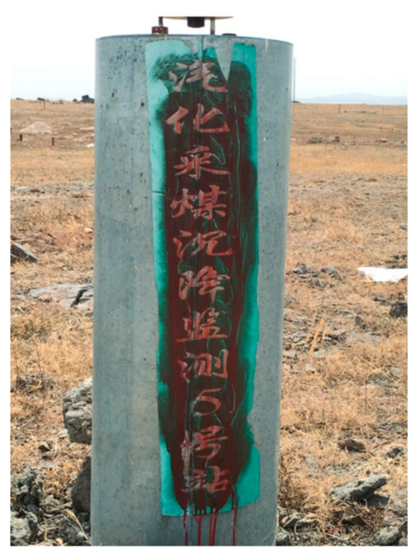
The gasification experiment station adopted a CRIP process for UCG with a total of four strips gasified and mined, a designed gasifier width of 16 m, an isolated coal column width of 32 m, a strike length of 136 m, a tendency length of 170 m, and a coal seam thickness of 5 m. A high-precision GNSS ground subsidence monitoring station (CG05) was set up in the center of the gasification mining area and the maximum ground subsidence after mining was 36 mm.
Figure 1 shows the layout of the working face.
3. Coal–Rock High-Temperature Burnt Characteristics
During the expansion of the combustion cavity in UCG, inside the gasification channel, a high temperature of more than 1000 °C is generated [
31]. When the temperature field expands in the surrounding rock of the combustion cavity, various physical and chemical changes occur in the coal and rock within the influence range of the temperature field. This event then affects its mechanical properties, resulting in coal and rock burnt, and changes the surface subsidence law of underground gasification.
Figure 2 shows that Young’s modulus, tensile strength, cohesion, and angle of internal friction of sandstone decrease with increasing temperature. In
Figure 2, p/p
To is the ratio of mechanical properties of coal-rock at a certain temperature to that at room temperature, where T0 is 20 °C. The figure shows that Poisson’s ratio tends to decrease and then increase. The tensile strength, cohesion, angle of internal friction, and Poisson’s ratio of mudstone follow a similar pattern of change with temperature, becoming 0.4 times greater at 600 °C, whereas Young’s modulus increases and then decreases.
4. Simulation Study on Strata Movement Characteristics in UCG
The most important difference between UCG and conventional mining is the high-temperature environment of goaf. The high-temperature environment brings thermal stress and coal–rock burnt around of combustion cavity. In this study, the numerical model is established based on Ulanqab China Gasification Experimental Station. Moreover, the characteristics of overlying strata movement and surface subsidence under conventional mining, thermal stress, coal–rock burnt, and their synergistic effects are compared and studied. The objective is to explore the main controlling factors affecting the strata movement characteristics of surrounding rock in the combustion cavity.
4.1. Numerical Simulation
The numerical models were developed based on the geological mining conditions of the gasification experiment station in Ulanqab, China, with a length of 600 m, a width of 600 m, and a height of 332 m (
Figure 3). The model was built by ignoring the special combustion cavity morphology; only the expanding process of temperature and burnt fields is considered. The model consists of a square grid, and the Mohr-Coulomb model is chosen for the present model.
Table 1 and
Table 2 show the initial thermodynamic and material mechanics parameters chosen for the model thermal coupling calculation process. FLAC3D 5.0 numerical simulation software was used for numerical calculation. In the numerical calculation process, materials’ thermal parameters were considered constant, and their mechanical parameters changed with temperature. The law of mechanical parameters of coal and rock that change with temperature in
Section 2 was introduced into the simulation calculation process using the fish language.
The model uses fixed boundary conditions where the horizontal boundary of the model is fixed (displacement is 0 and velocity is 0), the lower boundary of the model is fixed (displacement is 0 and velocity is 0), and the upper boundary of the model is a free boundary. The model was tuned for the best simulation results using the measured surface subsidence data (maximum sink volume of 36 mm).
To analyze the main controlling factors affecting rock movement and surface subsidence, the following four simulation scenarios were adopted: (1) traditional mining model, (2) under thermal stress only, the mechanical properties of the coal rock do not change with temperature, (3) under high-temperature burnt only, the mechanical properties of the coal rock change with temperature, and the coefficient of thermal expansion is 0, (4) synergistic effect of thermal stress and coal–rock high-temperature burnt.
4.2. Simulation Results
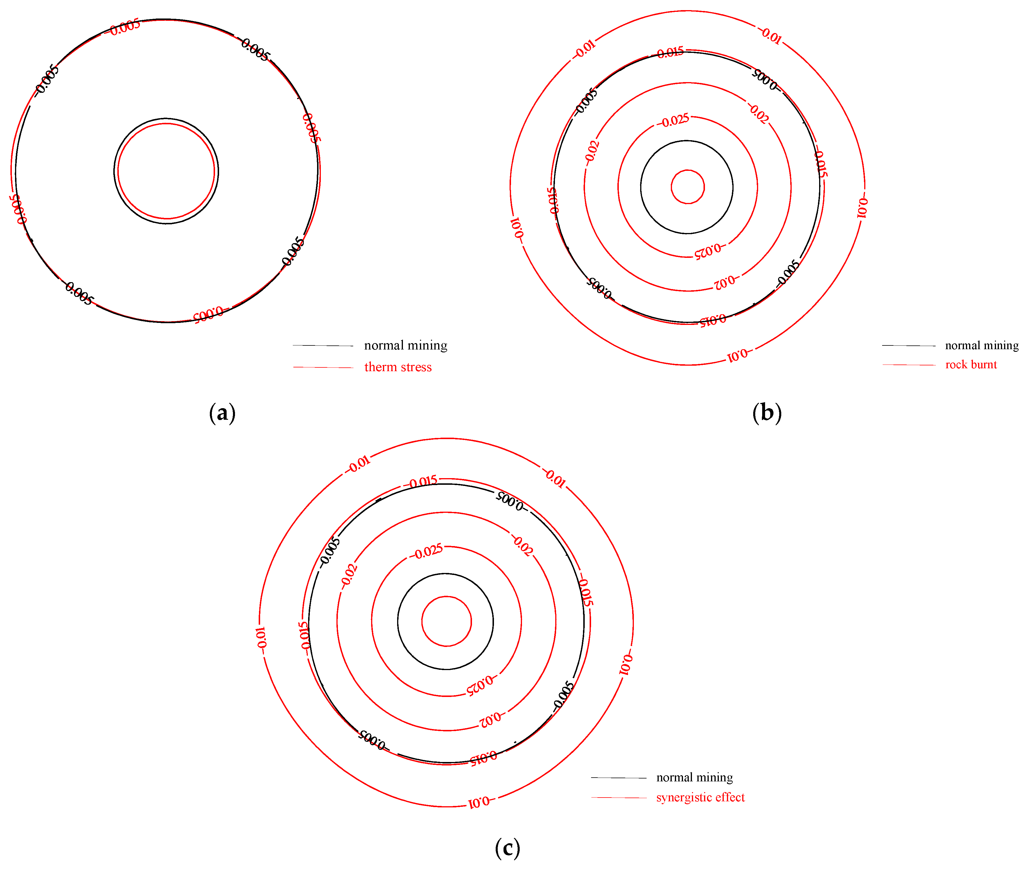
4.2.1. Surface Subsidence Characteristics
During the UCG process, the deformation of the surrounding rock in the combustion cavity is gradually transferred upward, eventually forming a subsidence basin at the surface. Surface subsidence will not only threaten the safe use of buildings and structures but will also cause ecological degradation of the surface. A surface subsidence of 10 mm can be used as the boundary of the subsidence basin. Combined with
Figure 4, the maximum surface subsidence under conventional mining conditions is 0.01 m, the maximum subsidence is the same when there is only thermal stress, and the range of subsidence is also the same. The maximum surface subsidence under high-temperature burnt of the surrounding rock increases steeply to 0.03 m. The maximum subsidence value does not change under high-temperature burnt and thermal stress nor the subsidence area. The main cause of increased subsidence in underground gasification coal mining is the high-temperature burnt of the surrounding rock in the combustion cavity, whereas thermal stress has little effect on surface subsidence.
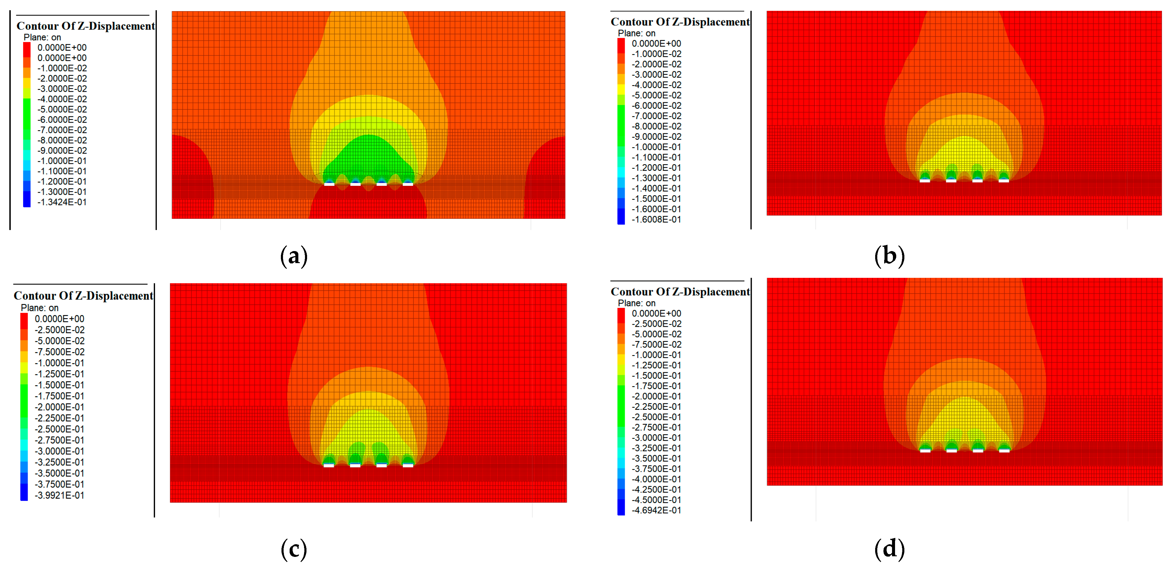
4.2.2. Movement Characteristics of Surrounding Rock in the Combustion Cavity
As shown in
Figure 5, under conventional mining conditions, the maximum subsidence of the goaf roof is 0.13 m and the maximum subsidence increases slightly to 0.16 m under the action of thermal stress only, then increases sharply to 0.4 m at coal–rock burnt condition. Moreover, the maximum subsidence of the roof is −0.46 m under thermal stress and high-temperature burnt synergistic effect. The propagation pattern of the overburden deformation in the strata is similar. The overburden deformation is less affected by thermal stress and increases sharply under the impact of coal–rock burnt, but the increase is not evident with the synergistic effect.
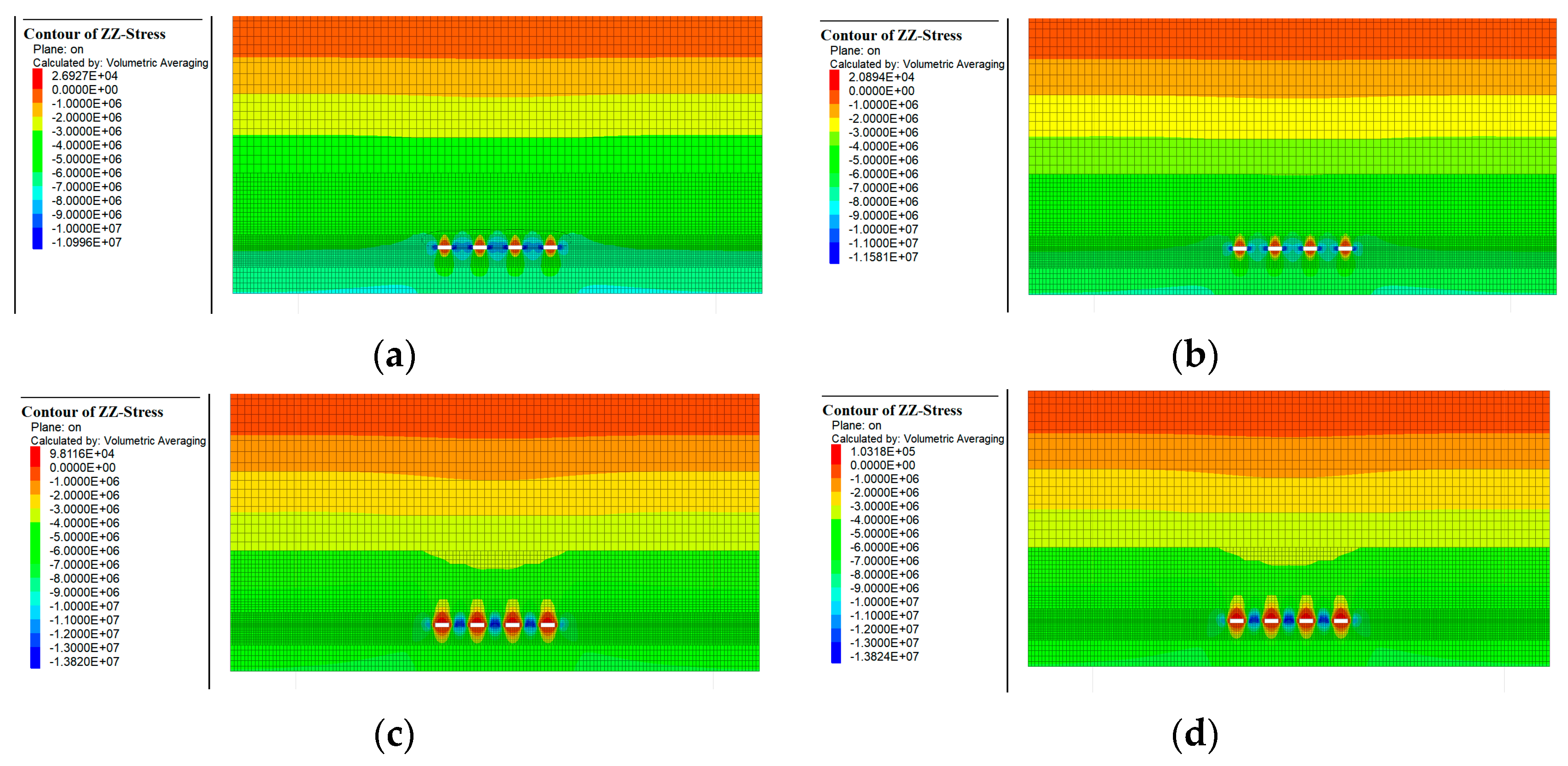
4.2.3. Vertical Stress Distribution of Surrounding Rock in Combustion Cavity
As shown in
Figure 6, the vertical stress distribution pattern inside the strata is similar under different conditions. The farther away from the combustion cavity, the smaller the stress is until the original rock stress is restored. In the vertical direction, the closer to the combustion cavity, the smaller the vertical stress is. Moreover, the farther away from the combustion cavity, the greater the stress is until the original rock stress is restored. However, the extreme stress varies greatly under different conditions, with a maximum value of −13.8 MPa when the surrounding rock is subjected to both thermal stress and coal–rock burnt, the same stress when the rock is subjected to high-temperature burnt only, a minimum value of −10.9 MPa when there is no thermal effect, and a slight increase in vertical stress of −11.5 MPa when the surrounding rock is subjected to thermal stress only. From the above analysis, both the high-temperature thermal stress and surrounding rock burnt affect the redistribution of stresses within the combustion cavity. However, the coal–rock burnt has the most significant effect, whereas thermal stress has a smaller effect.
From the numerical simulation results, the main controlling factor that changes the movement and deformation characteristics of the UCG combustion cavity surrounding rocks is the change in the physical and mechanical properties of the coal-rock caused by the high-temperature burnt. Moreover, the high-temperature thermal stress generated in the underground gasification process has less influence on the rock movement and overburden deformation.
5. Surface Subsidence Prediction Method for UCG
In UCG mining, the roof collapse will lead to gasifier instability and damage. Therefore, the gasifier is generally designed to control the roof deformation with a large coal pillar width, whereas the mining width is small. At this time, the basic roof of the goaf will bend but not break after gasification [
39]. Therefore, continuous medium mechanics can be used to describe the movement and deformation of the basic roof. The process of mining space transferring upward along the strata can be described using the probability integral method [
41].
Based on the above two theories, this study calculated the roof subsidence space using the mechanical analysis method, regarded the roof subsidence space as the mining space, and used the probability integral method to predict the surface subsidence.
5.1. Basic Roof Subsidence Space Calculate
When the UCG process is complete, a gasification area will be formed, which is composed of the combustion cavity and isolated coal pillar. Similar to traditional strip mining, the roof stress will be released after the coal resources in gasifiers are consumed, resulting in roof subsidence. The stress of the overburdened strata concentrates on the isolated coal pillar, roof, and floor to form additional load, which causes the compression of the coal pillar, roof, and floor, where the stress concentrates and finally forms the subsidence space of the roof.
Therefore, the subsidence space of the roof in UCG consists of four main components. (a) The bending and subsidence of the roof in the combustion cavity. (b) The roof subsidence is caused by the compression of the coal pillar. (c) The compression of the floor causes the roof subsidence. (d) The roof subsidence is caused by the compression of the floor. The subsidence of these four components is calculated separately and added together to obtain the final sink space in the roof slab.
5.1.1. Combustion Cavity Surrounding Rock High-Temperature Burnt Characteristics
Based on the above analysis, the main factor affecting the surface subsidence characteristics of UCG is the high-temperature combustion of surrounding rock in the combustion cavity. Therefore, to calculate the basic roof subsidence space, the temperature field of the surrounding rock should be calculated first, and the variation characteristics of surrounding rock mechanical parameters should be calculated according to the results in
Section 2.
Assuming that a stable temperature can be reached in the combustion cavity after gasification, and the temperature propagation in the rock strata conforms to the Fourier heat conduction law, and the distribution of temperature in the rock strata during gasification is as follows:
where
x is the distance within the strata from the combustion cavity boundary,
t is the gasification time,
Ts is the gasification surface temperature,
T0 is the original temperature in strata, and
a is the thermal diffusion coefficient
.
According to Equation (1), to calculate the temperature field distribution in the roof and floor, the roof and floor are divided into
n sections on average to calculate the average temperature
Ti. According to the properties with a temperature change of Young’s modulus in
Section 2, the average elastic modulus
Ei of each section in the roof and floor is calculated, where the elastic modulus in the roof and floor is
Eri and
Efi, respectively.
According to the variation law of coal mechanical properties with temperature, the coal pillar loses its carrying capacity when the temperature exceeds 200 °C, and the width Fl of the failed coal pillar can be calculated from Equation (1). Assuming that the width of the original isolated coal pillar is cl and the width of the combustion cavity is gl, the width of the effective coal pillar is and the width of the effective combustion cavity is .
5.1.2. Roof Subsidence in the Combustion Cavity
After the completion of gasification, several combustion cavities with roof exposure exist between isolated coal pillars. In general, the length of each mining combustion cavity is much larger than its width. Thus, it can be regarded as a simply supported beam system under uniform load. In this case, the differential deflection equation of the basic roof rock beam above the combustion area is as follows:
Er is the average elastic modulus of the basic roof, due to the roof burnt , k is the number of layers within the influence range of the temperature field inside the roof, Ir is the moment of inertia of the roof, , wb is the relative deflection of the roof in the combustion cavity, q is the load of the overburdened strata , r is the average bulk density of the overlying strata, H is the thickness of the roof to the surface, and n is the number of combustion cavity.
The boundary equation under the simply supported beam condition is as follows:
The roof deflection of the combustion cavity can be solved as follows:
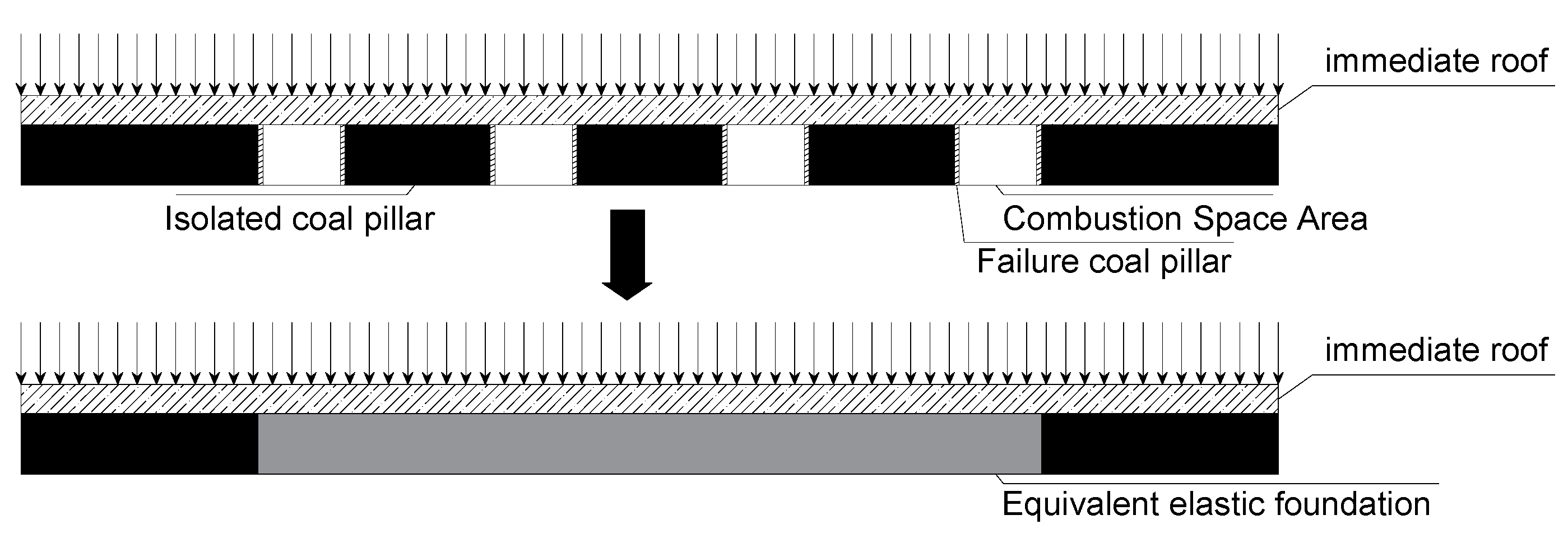
5.1.3. Isolated Coal Pillar Compression in the Gasification Area
After the coal is gasified, the stresses of overburdened strata concentrate on the isolated coal pillar, forming an additional load and causing pillar compression. To calculate the compression of coal pillar caused by stress concentration, the isolated coal pillar can be regarded as a continuously distributed Winkler elastic foundation (
Figure 7).
In this case, its equivalent elastic coefficient is set as
k, and then, the calculation method of
k is as follows:
Ec is the elastic modulus of coal, and h is the thickness of the coal seam.
Assuming that the load acting on the coal pillar is a uniform load, the additional load
q acting on the elastic foundation resulting in the compression of the coal pillar can be calculated by the following formula:
According to Winkle’s elastic foundation theory, the compression of the coal pillar is directly proportional to the pressure at the point.
Thus, the differential equation of roof deflection continuously can be derived as follows:
The general solution of the homogeneous differential equation above is as follows:
Among them, C1, C2, C3, and C4 are undetermined coefficients.
The particular solution of the non-homogeneous differential equation is as follows:
Then, the solution of the differential equation is as follows:
Assuming that the two ends of the beam on the elastic foundation are simply supported, there are boundary conditions.
Thus, the undetermined coefficient can be obtained and the roof subsidence space caused by coal pillar compression can be calculated.
5.1.4. Roof and Floor Compression Caused by Stress Concentration
From the analysis in
Section 4.2.3, the compression amount at different locations of the coal pillar is also different, which indicates that the stress concentration of the overburdened load on the coal pillar at different locations is also different. Assuming that the additional load caused by stress concentration is uniform, the additional stresses in the overburdened rock carried by the coal pillar are calculated from the coal pillar compression amount as follows:
The stress concentration at the coal pillar will cause compression of the coal seam and the rock at the roof and floor. Moreover, the additional stress at depth
z at any point in the foundation for a strip foundation under uniform load can be derived from Boussinesq’s formula, expressed by the following equation:
N is the ratio of the depth at any point in the foundation to the width of the strip foundation, .
The compression of each rock layer in the roof and floor can be calculated by the following formula:
si is the compression of layer i at the roof or floor of the coal pillar.
zi is the distance between the upper surface of layer i at the bottom of the coal pillar and the coal seam floor or the distance between the lower surface of layer i at the top of the coal pillar and the roof of the coal seam.
zi+1 is the distance between the upper surface of layer i + 1 at the bottom of the coal pillar and the coal seam floor, or the distance between the lower surface of layer i + 1 at the top of the coal pillar and the roof of the coal seam.
Ei is the elastic modulus of the combustion rock strata in the i layer of the coal pillar roof or floor.
wr is the total compression of n beds.
Φ is the empirical coefficient in the calculation of foundation compression, which can be obtained from
Table 3.
5.1.5. Calculation of the Total Roof Subsidence Space
From the above analysis, the total subsidence space of the roof is composed of the deformation of the roof, the compression of the coal pillar, and the compression of the roof and floor. The calculation formula is as follows:
where
k is the number of combustion cavities.
5.2. Surface Subsidence Prediction Method Based on the Roof Subsidence Space
In the prediction of surface subsidence caused by coal mining, the probability integral method based on random medium theory is one of the most mature and effective methods, which is widely used in the prediction of surface subsidence under various mining technologies. From the basic theory of stochastic media, the number of resources mined in volume per unit at underground coordinates
s causes subsidence at any point
x on the ground surface as [
43]:
we is the surface subsidence at x caused by unit mining at coordinate s, and r is the main influence radius.
If the mining thickness here is
m and the subsidence coefficient is
q, then the subsidence at
x of the surface is as follows:
Through the above analysis, we obtain the calculation method of the roof subsidence space of UCG mining, and the roof subsidence space can be regarded as mining space. Meanwhile, under similar geological and mining conditions, the ratio of main influence radius
r to mining depth
H is constant. We call it the tangent of the major influence angle, and the calculation method is
. At this time, the surface subsidence prediction model of UCG is as follows:
where
W(x) is the subsidence at the surface coordinate
x, and
wg(x) is the roof subsidence space at the coordinate
m.
Equation (23) is the formula for predicting surface subsidence caused by UCG.
6. Results and Discussion
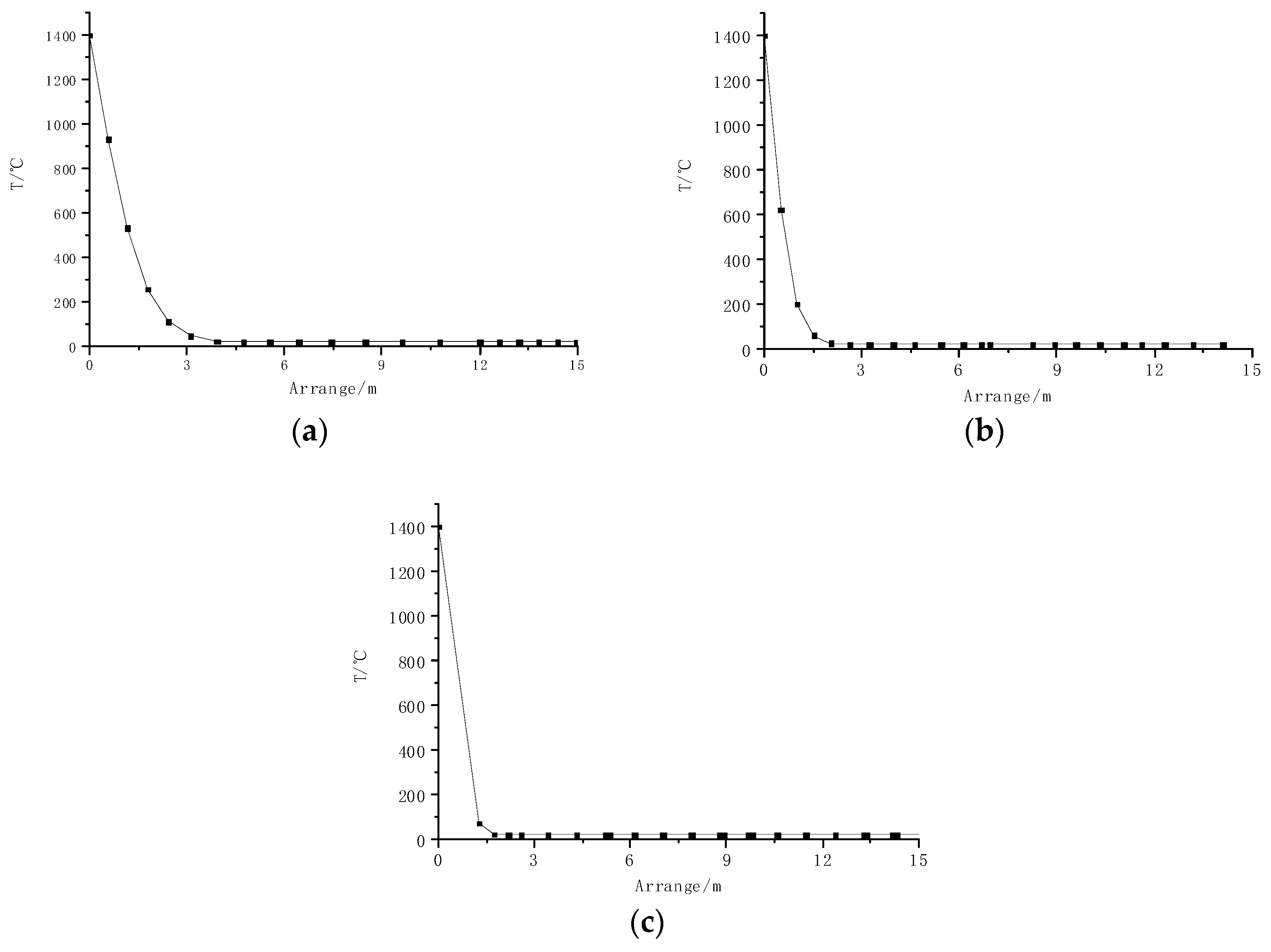
Combined with the geological and mining conditions of the experimental area, the UCG test station mining is 4 strips, the gasifier mining depth is 259 m, the combustion cavity width is 16 m, and the isolation coal pillar width is 32 m. The gasification time of each strip was 3 months, and the combustion surface temperature was 1400° after the gasification of the gasifier was stabilized. The temperature field distribution of the roof, floor, and coal walls on both sides after gasification can be calculated as shown in
Figure 8.
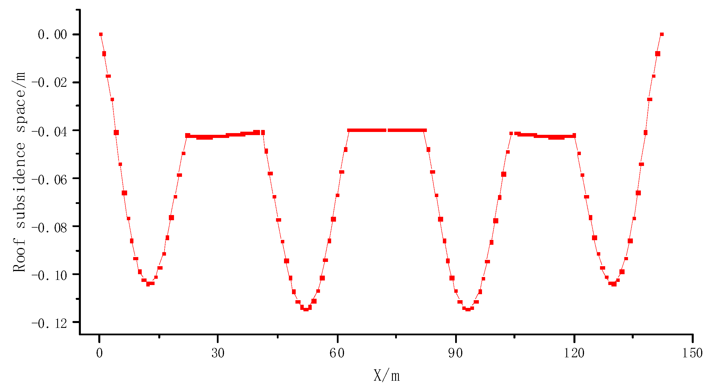
The mechanical parameters distribution of the surrounding rock around the combustion cavity was calculated according to the temperature field expansion characteristics. The basic roof subsidence was obtained using the calculation method of the basic roof subsidence space of UCG, as shown in
Figure 9.
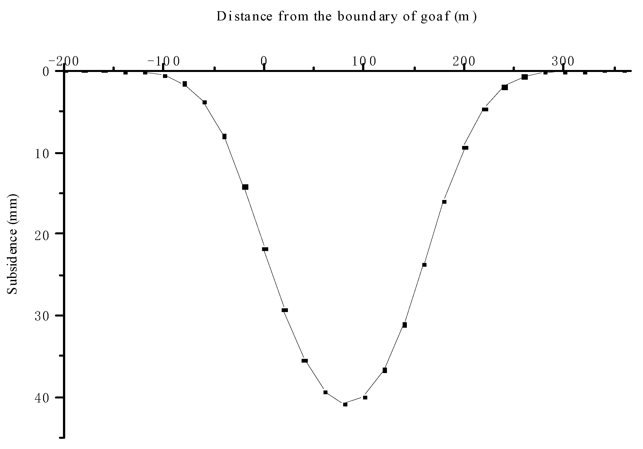
As the roof subsidence space is small, the rock layers can be considered to have no delamination between them. At this time, the subsidence space of the roof subsidence upward transfer process follows the principle of equal volume. At this time, the subsidence coefficient can be considered to be 1. By comparing the geological conditions of the mining area near Ulanqab, the main influence angle tangent is 1.8. The expected method of UCG surface subsidence is used to calculate its surface subsidence curve as shown in
Figure 10. According to the figure, the expected maximum surface subsidence is 41 mm and the measured maximum surface subsidence in the experimental area is 36 mm, which is expected to be 11% different from the measured results. This method can be used to predict the surface subsidence of UCG.
Through numerical simulation, we found that the thermal stress and coal-rock burnt by high temperature affect the strata movement characteristics of UCG, of which the coal-rock burnt is the main control factor. Although the high-temperature thermal stress has a certain contribution to this process, its impact is relatively small.
There have been studies reporting the impact of high temperature on the movement and deformation of strata during UCG, but most of the literature only studies the impact of high-temperature thermal stress or comprehensively considers high-temperature thermal stress and coal-rock burnt, resulting in insufficient research or increasing the complexity of subsequent research [
22,
44,
45]. Undoubtedly, our research is consistent with previous results. Whether it is high-temperature thermal stress or coal-rock burnt, it will increase the degree of movement and deformation of the overlying strata. Our research results can grasp the main influencing factor of coal-rock burnt, omitting the subtle elements and simplifying the subsequent research process based on not affecting the research results.
Currently, the prediction of surface subsidence caused by UCG is generally reference strip mining ignoring the influence of high temperature, resulting in limited prediction accuracy [
26,
46,
47]. In this study, considering the coal-rock burnt, the prediction model of surface subsidence of UCG is established by innovatively combining the elastic foundation beam theory and random medium theory. We applied this method to the UCG test station in Ulanqab and estimated a maximum surface subsidence of 41 mm (
Figure 11). At the same time, we established a continuous observation station for surface subsidence on the surface and observed a maximum surface subsidence of 36 mm with a difference of only 5 mm. This proves that the method proposed in this paper has high prediction accuracy.
The author believes that improving UCG efficiency while reducing its environmental risks is currently a research focus in the field. Among them, controlling the movement and damage of overlying strata is one of the essential means to ensure the efficiency of underground gasification and reduce environmental damage. In subsequent research, the focus will be on how to reasonably set the width of the goaf isolation coal column and control ecological risks while ensuring UCG recovery rate.


