Article

Fault Diagnosis of Wind Turbine Planetary Gear Based on a Digital Twin

School of Intelligent Manufacturing Modern Industry, Xinjiang University, Urumqi 830046, China
*
Author to whom correspondence should be addressed.
Appl. Sci. 2023, 13(8), 4776; https://doi.org/10.3390/app13084776
Submission received: 15 March 2023 / Revised: 1 April 2023 / Accepted: 6 April 2023 / Published: 10 April 2023
(This article belongs to the Topic Advanced Systems Engineering: Theory and Applications)

Abstract

:
Aiming at the problems of the traditional planetary gear fault diagnosis method of wind turbines, such as the poor timeliness of data transmission, weak visualization effect of state monitoring, and untimely feedback of fault information, this paper proposes a planetary gear fault diagnosis method for wind turbines based on a digital twin. The method was used to build the digital twin model of wind turbines and analyze the wind turbines’ operating state utilizing virtual and real data. Empirical mode decomposition (EMD) was used, and an atom search optimization–support vector machine (ASO-SVM) model was established for planetary gear fault diagnosis. The digital twin model diagnoses faults and constantly revises the model based on the diagnostic results. The digital twin fault diagnosis system was implemented in the Unity3D platform. The experimental results demonstrate the feasibility of the proposed early-warning system for the real-time diagnosis of planetary gear faults in wind turbines.

1. Introduction

In the face of global energy shortages and increasing atmospheric warming, wind power generation, producing clean and renewable energy, has become one of the most trusted forms of power generation [1]. However, wind turbines often break down due to their harsh operating environment, leading to unexpected shutdowns and economic losses [2]. The wind turbine transmission system gear is often complicated in structure, has a high failure rate, and failure sites are not easy to find in time. The accompanying economic loss accounts for the largest proportion of each fan component [3]. Therefore, realizing the real-time monitoring and intelligent diagnosis of the planetary gear of wind turbines is of great significance for safe and stable operation.
At present, gear fault diagnosis methods mainly include those based on expert systems, physical models, and those that are data-driven [4,5,6]. Compared with the first two methods, the data-driven fault diagnosis method has the advantages of low requirements for professional knowledge and easy access to data. In this era of mature sensor technology [7] and big data analysis, scholars in the industry favor the data-driven fault diagnosis method. Data-driven fault diagnosis methods mainly include traditional machine learning algorithms [8] and deep learning models [9]. Although deep learning models, such as convolutional neural networks [10], long- and short-term memory networks [11] and automatic encoders [12], have outstanding achievements in feature extraction, they still have defects such as large sample sizes and long training times. Traditional machine learning algorithms can perform better when historical data samples are limited. However, all the data-driven diagnosis methods collect the data, conduct an offline analysis, and then obtain the diagnosis results. Therefore, it is crucial to seek new technical methods to solve the problems of the data acquisition, condition monitoring, and fault diagnosis of planetary gear of wind turbines during operation.
With the development of the fourth Industrial Revolution, the need for digital and intelligent equipment operation and maintenance is becoming increasingly urgent. Researching digital twin technology and machine learning algorithms that combine data and physics has become a top priority. Professor Grieves first proposed the digital twin concept in 2002 [13], which establishes a mirror model of a physical entity in the digital space. With the continuous innovation of network information technology, digital twin technology has also been rapidly developed. The virtual model and physical entity data connection interactive mapping are completed by establishing the digital twin model and using sensor technology. Furthermore, the simulation and health monitoring, diagnosis, and maintenance can be realized by analyzing the collected data information [14].
As the research of digital twin technology becomes more in-depth, the recurrence of technology is becoming increasingly mature; the development potential is huge, and the technical concept is constantly expanding. At the same time, digital twin technology is becoming more widely used in online monitoring and intelligent equipment diagnosis. For example, Tao et al. [15] proposed a five-dimensional digital twin model, which added the composition of the service system and communication connection to the original three-dimensional structure and realized the fault prediction and health management method driven by the digital twin. However, this research is only theoretical, and much work is needed before a complete reproduction can be achieved. Liu et al. [16] proposed a ship structure bearing a monitoring system based on a digital twin. Through a local stress correlation method, the stress monitoring data collected by sensors are applied to the digital twin model of the ship monitoring structure to realize the health management of the ship structure and greatly reduce the cost of ship maintenance. However, this study only focuses on the analysis and research of offline data collection and needs the capability of real-time monitoring and diagnosis. Li et al. [17] proposed a gear test bench condition monitoring method based on a digital twin. By obtaining the physical information, the digital twin model simulates the gear running state in real time and carries out simulation analysis and verification to realize the monitoring of the running state and improve the operating stability of the gear test bench. However, this method only realizes condition monitoring based on real-time data and does not continue to complete further data mining analysis. Aiming at the problems of inconvenient multi-robot monitoring and poor real-time performance, Zong et al. [18] developed a set of multi-robot monitoring systems based on digital twin technology. By collecting data through OPC Unified Architecture (OPC UA), they realized the multi-robot cooperative collision test and improved the factory’s production efficiency. However, this system only involves monitoring the robot arm’s working state. It does not involve monitoring the equipment’s operating state and deeper data analysis.
Digital twin technology also provides a new concept and method for intelligent equipment fault diagnosis. Zhang et al. [19], aiming at the problem of obtaining fault data in advance for rolling-bearing fault diagnosis, proposed a rolling-bearing fault diagnosis method based on a digital twin. By constructing a dynamic virtual model to generate simulation data and adopting a partial adaptive algorithm, the twin model can accurately diagnose the health condition of actual rolling bearings under unknown fault conditions. Thus, the safe operation of bearings is ensured, and the maintenance cost is reduced. However, this method is still in the offline data analysis and diagnosis stage and cannot achieve real-time online analysis and diagnosis. Xiong et al. [20] developed a real-time field-programmable gate array-digital twin (FPGA-DT) technique. By constructing recognizable feature vectors and combining digital twinning technology to diagnose and classify system faults, the online real-time diagnosis of the transformer is realized, greatly improving the efficiency and accuracy of fault diagnosis. However, the system hardware requirements are relatively high and cannot universally achieve the system. Guo et al. [21] proposed an improved random forest (IRF) algorithm based on a digital twin. The digital twin’s fault diagnosis method added to the basis of the traditional machine learning algorithm not only improves the fault diagnosis accuracy but can also quickly discover and locate the fault location. Focusing on the disadvantage that historical and static data drive traditional satellite system fault diagnosis and health monitoring methods, Shangguan et al. [22] proposed a fault diagnosis method for complex satellite systems based on a digital twin. By integrating simulation data and real-time data, the real-time diagnosis and maintenance of in-orbit satellites are realized, and the reliable operation of the satellite system is ensured, greatly reducing the operator’s workload. However, the requirements and accuracy of the data are very strict, so the diagnosis cannot be realized quickly or conveniently.
The above work shows that digital twin technology has good application prospects and excellent practicability in equipment condition monitoring and fault diagnosis. However, there are few studies on the condition monitoring and intelligent maintenance of planetary gear of wind turbines by using digital twin technology and online fault diagnosis by collecting real-time data. Given this, a fault diagnosis system for planetary gear of wind turbines based on digital twinning is proposed in this paper. The strain signal of the gear is collected and analyzed for online diagnosis, and it is successfully applied to the fault diagnosis test bench of the wind turbine. Compared with existing research, the main contributions of this paper are summarized as follows: (1) A digital twin virtual model based on the collected parameters is built, scripts are written to complete the accurate behavior mapping between the virtual model and the physical entity, and the interaction between virtual and real data is realized through data acquisition, transformation, transmission, and other methods to complete the real-time visual status monitoring of the wind turbine; (2) A data-driven fault diagnosis method based on empirical mode decomposition (EMD) and atom search optimization–support vector machine (ASO-SVM) is proposed to diagnose and predict the operating state of planetary gear by identifying strain signals of outer gear rings of the wind turbine planetary gearbox, which effectively improves the accuracy of fault diagnosis and does not require a large amount of data for a calculation that requires a long time; and (3) The combination of the fault diagnosis method and digital twin technology can realize the online fault diagnosis and location, realize the high efficiency and intelligence of fault diagnosis, and solve the problem of the wind turbine planetary gear fault diagnosis being untimely and difficult to maintain. Finally, the system’s feasibility is verified on the laboratory’s wind turbine fault diagnosis test bed.
The rest of this article is organized as follows. Section 2 introduces the construction method and architecture of the digital twin system of the wind turbine transmission system, including the construction of a twin model, the composition of twin data, acquisition, and data transmission, and analysis of virtual-real interaction. Section 3 introduces the fault diagnosis method of EMD-ASO-SVM based on a digital twin. Section 4 is an experimental example of the wind turbine’s digital twin planetary gear fault diagnosis system. It verifies the feasibility of the planetary gear fault diagnosis system based on a digital twin. Section 5 discusses the contributions of this paper and future research directions. Section 6 provides the conclusions of the report.

2. Establishment of a Digital Twin of the Wind Turbine Transmission System

Digital twinning establishes a multi-scale and multi-physical quantity simulation model using data from a physical object and other information. A two-way interactive feedback mechanism is established to update the digital twin using real-time information from the physical object. Since there is a lack of real-time fault diagnosis methods, a digital twin is established within the present study to perform real-time online fault diagnosis to determine a wind turbine transmission system’s operating status and fault conditions. The digital twin model of the planetary gear of a wind turbine is presented in Figure 1. The model comprises the physical object, virtual model, twin data, and service system [23].

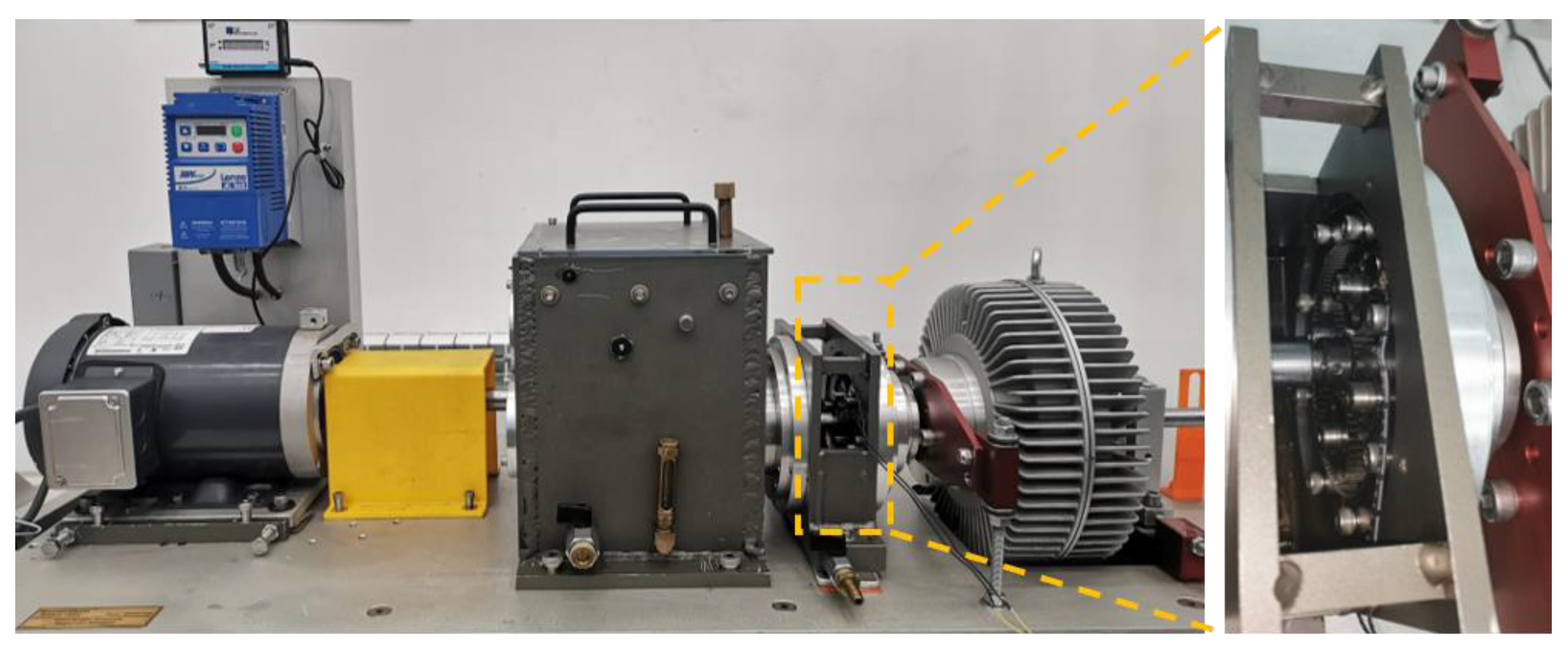
2.1. Wind Turbine Transmission System Entity

A digital twin of the wind turbine drive system is established. It consists of multiple function modules and sensors; the function modules consist of different units, as shown in Figure 2. The object of interest is a custom-made Spectra Quest test rig for the fault diagnosis of a wind turbine drivetrain. It consists of a motor, spur gearbox, planetary gearbox, and magnetic powder brake. The motor drives the transmission shaft, which powers the spur and planetary gearbox, transmitting power to the fan blade. The magnetic powder brake generates a magnetic field that pulls the armature toward the magnet, transmitting the torque. The spur gearbox comprises an input shaft, gear, output shaft, roller bearing, and other components. The roller bearing includes an outer ring, inner ring, and ball roller. The planetary gearbox is composed of the rodent ring, the planetary gear, and the sun gear.

2.2. Twin Model of Wind Turbine Transmission System

The first task of constructing a digital twin is to create a digital twin model of the object. The twin model connects the virtual model to the real object. Creating a digital twin of the wind turbine drive system consists of geometric modeling, scene construction, and modeling of the object’s status [24], as shown in Figure 3.
(1)
Geometric model
Establishing a geometric model includes modeling the geometric size and relationship of the physical components of the wind turbine transmission system. The geometry consists of the motor’s shape, size, tolerances, roller bearing, spur gearbox, planetary gearbox, and other components. The geometric relationships between the components are determined. The 3D modeling of the wind turbine drive system involves measuring the components’ sizes and shapes. A 1:1 3D modeling was performed in NX software, and the data were exported to an STL file format. This file was opened in 3DS Max software for rendering and format conversion. The rendered and transformed model was imported into Unity3D in the FBX format.
(2)
Scene construction
The scene construction of a digital twin model refers to the scenes of analog objects, including the external environment and the internal operating mechanism in different spatiotemporal conditions. This step is critical for the virtual space’s scene layout and functional design according to real-world conditions. Different materials are added for detailed rendering to obtain a realistic virtual scene. Wind farms are often constructed in harsh environments, such as wasteland areas near mountains and the ocean. Unity3D enables the generation of various environments.
(3)
Modeling of the object’s status
Modeling the object’s status is required to achieve virtual–real interaction. This model ensures that the virtual model performs the same actions as the real-world object. Timely model corrections can be made according to the environment and system uncertainty. A customized script based on the C# programming language was used in Unity3D to perform a dynamic simulation of the wind turbine drive system. The model was updated with real-time data to ensure the synchronous operation of the wind turbine in the virtual world and the physical world.

2.3. Composition of Twin Data

The data to establish a digital twin and run simulations are derived from information on the physical object and its environment and data obtained from simulations with various models. The interaction between the physical object and the virtual model and model updating and optimization is achieved by inputting massive amounts of multidimensional and dynamic data [25]. This strategy ensures a real-time relationship between the physical entity and virtual model, improves the operation of the digital twin, and allows for information sharing. The digital twin data of the wind turbine drive system include physical data, virtual simulation data, external environment data, and other knowledge data [26], as shown in Figure 4.
The physical data of the wind turbine drive system include the real-time operating status, unit parameter performance, sensor parameter information, data sampling frequency, and measurement point configuration. The virtual simulation data consist of geometric model data of the wind turbine (size, component relationships, positions, and operating data), influencing factors, operation logic, data obtained from the analysis model and boundary condition model, and the outputs. External environment data include ambient temperature, wind speed, and terrain. Other knowledge data include expert knowledge, industry standards, inference, equipment maintenance rule base, and fault diagnosis model data.

2.4. Data Transmission between the Virtual Model and Actual Wind Turbine Transmission System

The real-time acquisition of dynamic data of the wind turbine drive system is required as input into the digital twin. Ensuring the real-time transmission of dynamic data is crucial to establishing a 3D virtual model of the wind turbine drive system and achieving an intelligent transmission system. The link between the virtual model and physical entity and the data transmission process is presented in Figure 5.
The virtual–real interaction between the electrical equipment is achieved as follows: (1) The physical entity and the virtual model are connected using a universal asynchronous receiver/transmitter (UART) serial port. The dynamic information collected by the sensor is transmitted to the Unity3D platform in real time to reflect the running state of the wind turbine drive system. The status of the virtual model is updated in real time, and the data are saved in a MySQL cloud database. (2) The node.js language is used to read/write information from/to the database. This information is depicted in ECharts using a front-end HTML file. A URL link is created in Unity3D to integrate the web chart into the platform and visualize the dynamic data. (3) The calling function of the fault identification model is compiled in MATLAB into a C# dynamic link library using the deploytool toolbox. The C# language is used to invoke the dynamic link library in Unity3D to import the real-time data collected by the identification model to perform online fault diagnosis. (4) The virtual model promptly displays the wind turbine transmission system’s operating status and fault alarm signals and transmits the information to the staff. The staff then performs offline inspection, repair, and maintenance promptly according to the diagnostic results to ensure the safe and stable operation of the wind turbine and reduce economic losses.

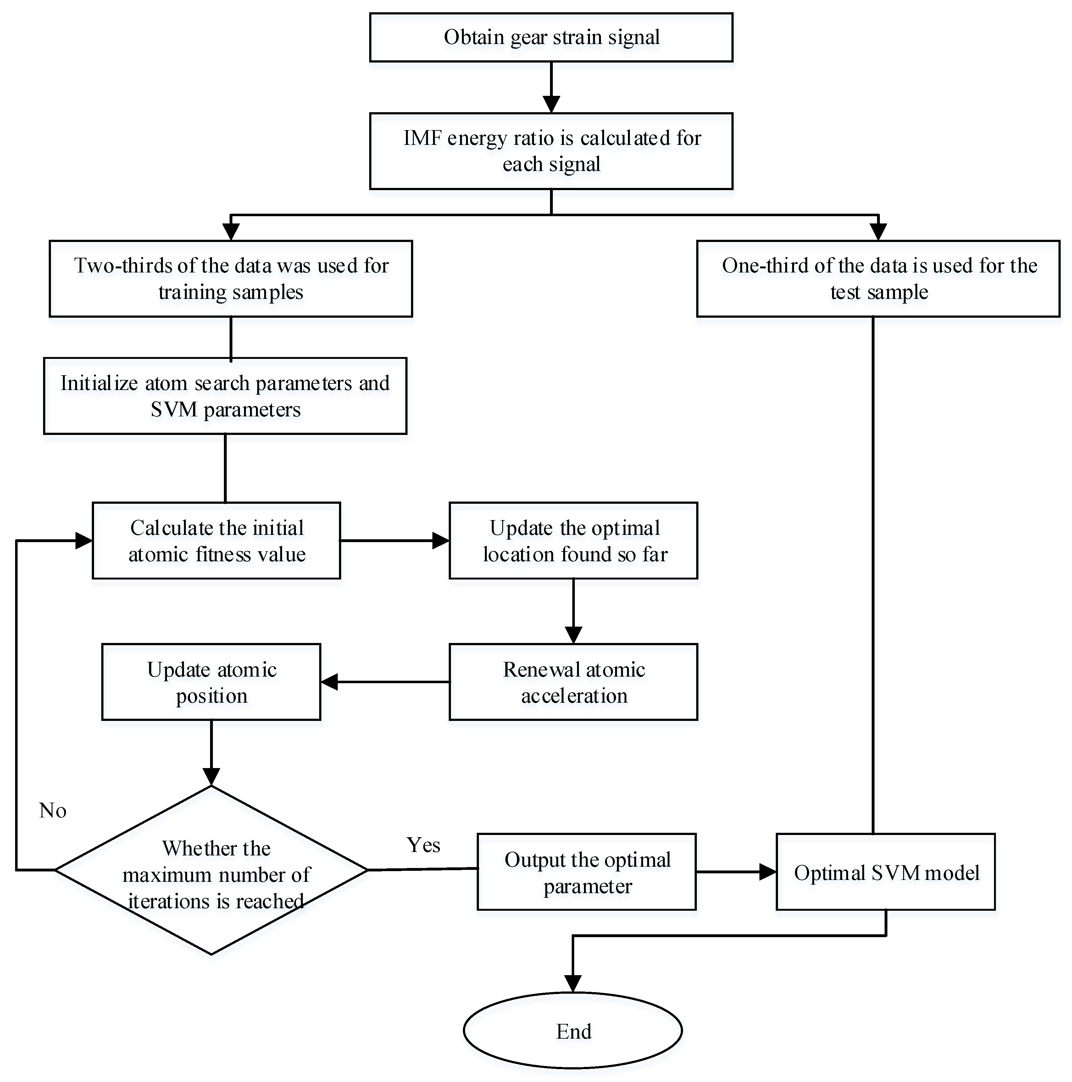
3. Fault Diagnosis Method Based on Digital Twinning

The planetary gear is used in the wind turbine transmission system. It has time-varying conditions, high-impact vibration, high speed, and a poor working environment. The planetary’s failure reduces the gearbox’s stability and may cause the wind turbine to malfunction. Therefore, the fault diagnosis of the planetary gear of wind turbines using a digital twin can address these problems. The intelligent monitoring and fault diagnosis model of the planetary gear of wind turbines based on a digital twin is shown in Figure 6.

3.1. Establishment of Fault Diagnosis Model

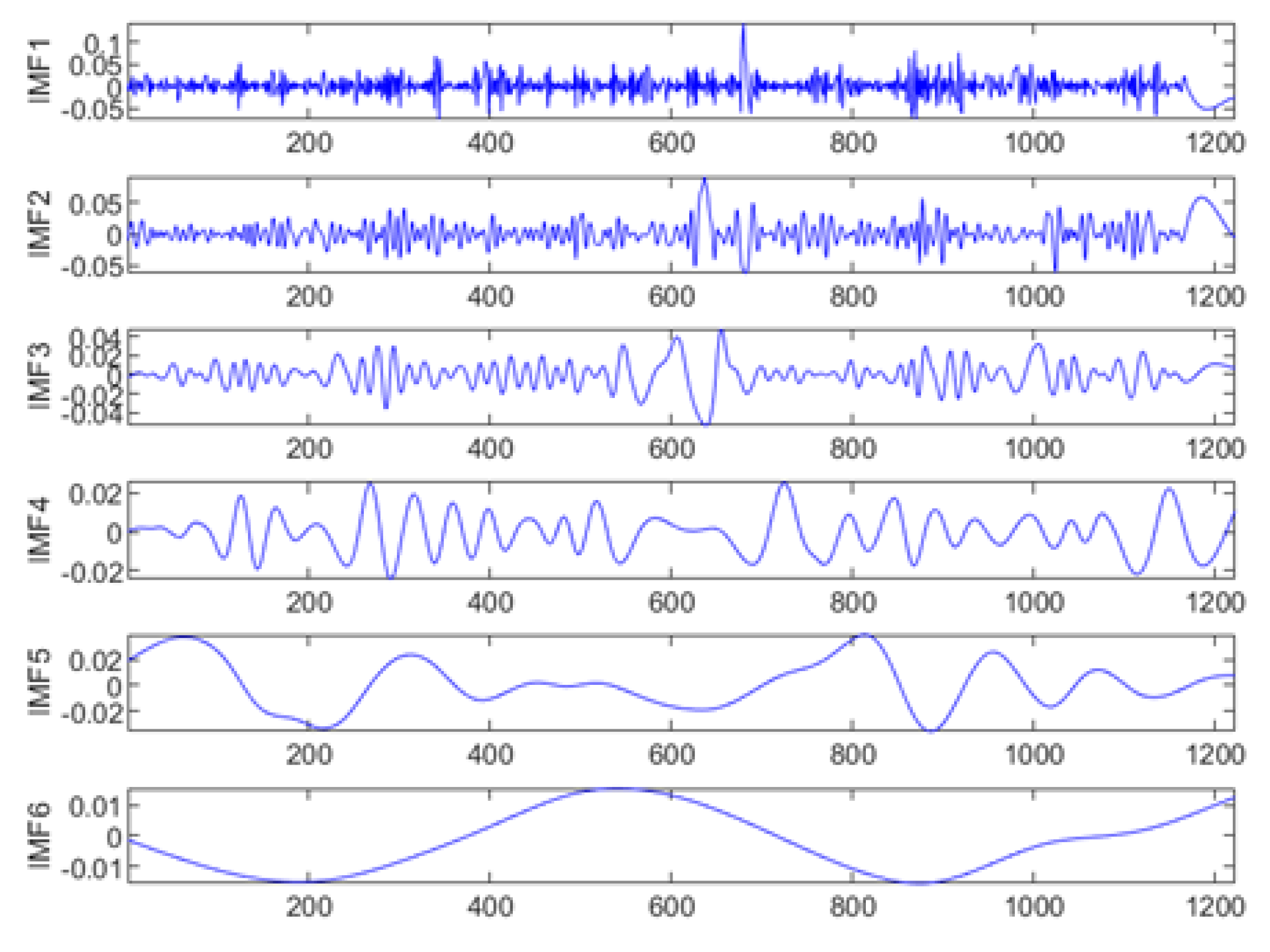
3.1.1. Feature Extraction Using Empirical Mode Decomposition

The EMD algorithm was proposed by Huang [27]. It can decompose the signal according to the time scale characteristics of the data without any basis function and has a high signal-to-noise ratio. Therefore, the EMD method is used in this paper. According to the strain signal’s energy characteristic information, the component’s energy entropy is decomposed to realize the selection of characteristic parameters, as shown in Figure 7.
First, the eigenmode function (IMF) is obtained after EMD decomposition, and the energy entropy of each IMF component is calculated [28]. Then, the feature vector is selected. The frequencies of different-order IMF components differ, and the higher the IMF order, the fewer high-frequency components it contains, as shown in Figure 8. Therefore, the IMF energy entropy of orders 1–5 is selected to design the classifier to improve feature vector extraction. The steps are as follows:
(1)
The signal is decomposed by EMD to obtain the IMF components c i = ( t ) .
(2)
The lines are summarized, and the energy entropy of each IMF E i = ( t ) is calculated:
E i = | c i = ( t ) | 2 d t
(3)
The energy proportion of each IMF is obtained and normalized:
p i ( t ) = E i ( t ) i = 1 n E i ( t ) ( i = 1 , 2 , , n )
(4)
The IMF energy entropy is defined as:
H = i = 1 n p i log p i

3.1.2. Atom Search Optimization–Support Vector Machine Algorithm

An SVM is a supervised learning model with relatively high classification accuracy and few samples. Support vector machines have been widely used in practical engineering [29]. The basic principle of an SVM is to find an optimal classification hyperplane to classify samples, as shown in Equation (4); the objective function is provided in Equation (5), and the classification model is given in Equation (6).
ω T x + b = 0 ,
s . t . { min 1 2 ω 2 + c i = 1 n ξ i y i [ ω t ϕ ( x i ) + b ] 1 ξ i , i = 1 , 2 , , n
g ( x ) = i = 1 n α i y i K ( x i , x ) + b ,
where ω is the weight vector; x is the sample feature; b is the offset item; ξ i is the relaxation factor; and c is the penalty factor. It can be seen from the formula that the value of c will affect the model’s generalization ability. If the value of c is too large, the training time will be long, and over-fitting will occur. If the value of c is too small, underfitting will occur. K ( x i , x ) is the kernel function, where g is the radius of the kernel function, and the value of g will directly affect the training speed and prediction speed of the model. Therefore, optimizing penalty factor c and kernel radius g can build a better SVM model.
In the present study, an SVM was combined with an ASO algorithm to improve the classification accuracy and optimize the penalty factor c and kernel radius g of the SVM.
Proposed in 2018 [30], ASO has become a popular optimization algorithm based on molecular dynamics. The algorithm is based on Newton’s second law. It simulates the motion of atoms in a molecular system, i.e., the force between atoms and the binding force of the system leading to displacement.
The atom’s mass influences its attraction and repulsion in the molecular system [31], namely:
a i = F i + G i m i ,
where F i is the interaction force acting on atom i ; G i is the covalent bond between atoms i ; and m i is the mass of atom i .
(1)
Interaction force F i d
The interaction force F i d represents the sum of the forces of the surrounding atoms on the current atom i ; it is defined as follows:
F i d ( t ) = j K b e s t r a n d j F i j d ( t ) ,
where t is the number of current iterations; r a n d j is the random number in the range of [0, 1]; d is the dimension of the atom; K b e s t represents a set of atoms with high fitness function values; and F i j d ( t ) represents the Lennard-Jones potential force on the atom i of the j iteration.
F i j d ( t ) = η ( t ) { 2 [ h i j ( t ) ] 13 [ h i j ( t ) ] 7 } ,
where η ( t ) is the depth function used to adjust the repulsive and attractive regions; and h i j is the distance between the two atoms.
η ( t ) = α ( 1 t 1 T ) 3 e 20 t T
h i j = r i j ( t ) σ ( t ) ,
where α is the depth weight; σ is the length, representing the collision diameter; and r i j is the Euclidean distance between atoms.
r i j = x i ( t ) , x j ( t ) 2 ,
σ ( t ) = x i ( t ) , j K b e s t ( t ) x j ( t ) K b e s t ( t ) 2 ,
where x i and x j are the positions of atoms i and j , respectively.
K b e s t ( t ) = N ( N 2 ) t T ,
where N is the total number of atoms; and T is the total number of iterations.
(2)
Covalent bond force G i d
The covalent bond force G i d represents the force of attraction between atoms; it is defined as follows:
G i d = β e 20 t T ( x b e s t d ( t ) x i d ( t ) ) ,
where β is the coefficient; x b e s t d ( t ) is the optimal position of the atoms in the t iteration; and x i d ( t ) is the position of atom i in the first iteration.
(3)
Atomic acceleration a i d
The equation for solving the acceleration of atom i in time t in dimension d is as follows:
a i d = F i d + G i d m i ( t ) = α ( 1 t 1 T ) 3 e 20 t T j K b e s t r a n d j [ 2 ( h i j ( t ) ) 13 ( h i j ( t ) ) 7 ] m i ( t ) + β e 20 t T ( x b e s t d ( t ) x i d ( t ) ) m i
The fitness value of the individuals determines the atomic mass m i ( t ) in the current population:
M i ( t ) = e f i ( t ) f min ( t ) f max ( t ) f min ( t ) ,
m i ( t ) = M i ( t ) j = 1 N M i ( t )
(4)
Iterative position update
In each iteration, the speed and position of the atoms according to their acceleration are updated as follows:
v i d ( t + 1 ) = r a n d i d v i d ( t ) + a i d ( t ) ,
x i d ( t + 1 ) = x i d ( t ) + v i d ( t + 1 ) ,
where v i d and x i d are the velocity and position of atom i ; and r a n d i d is a random number in the range of [0, 1].
An ASO method was used to optimize the SVM parameters, the ASO-SVM classifier was trained using a test sample, and the implementation process of optimization algorithm is shown in Figure 9.
This study randomly selected 2/3 of the data set (42 × 1300) from the laboratory’s wind turbine drive system failure test bench for sample training. The remaining 1/3 of the data was used in the test process. In the ASO process of SVM algorithms c and g, the parameter values of the atom search algorithm were initialized. The maximum iteration number was set to 200 and the initial atomic number was set to 10. The depth and multiplier weights were set for each iteration to 50 and 0.2, respectively. Two algorithms, SVM and ASO-SVM, were used for training, and the training results are shown in Figure 10. The accuracy of SVM without optimization was only 86.67%, while the accuracy of ASO-SVM was 6.67% higher than that of SVM. In conclusion, the ASO-SVM algorithm is superior to the traditional SVM algorithm in classifying and identifying gear faults.

3.2. Adjustment Method of Fault Diagnosis Model

The complex wind turbine equipment and the harsh and changeable operating environment result in various faults in the wind turbine’s planetary gear. The trained fault identification model can only identify existing faults but not new faults. Due to missing and insufficient sample data, inaccurate results may be obtained from the fault identification model. Therefore, the model must constantly be optimized to predict new fault types.
As the faults are detected and classified, the data are stored in a database for future retrieval and training to improve the knowledge base and enable the staff to investigate the reasons for the faults. After the operating status of the planetary gear has been evaluated, the newly collected and historical signal data are used to retrain the fault detection model to improve the model’s detection accuracy.

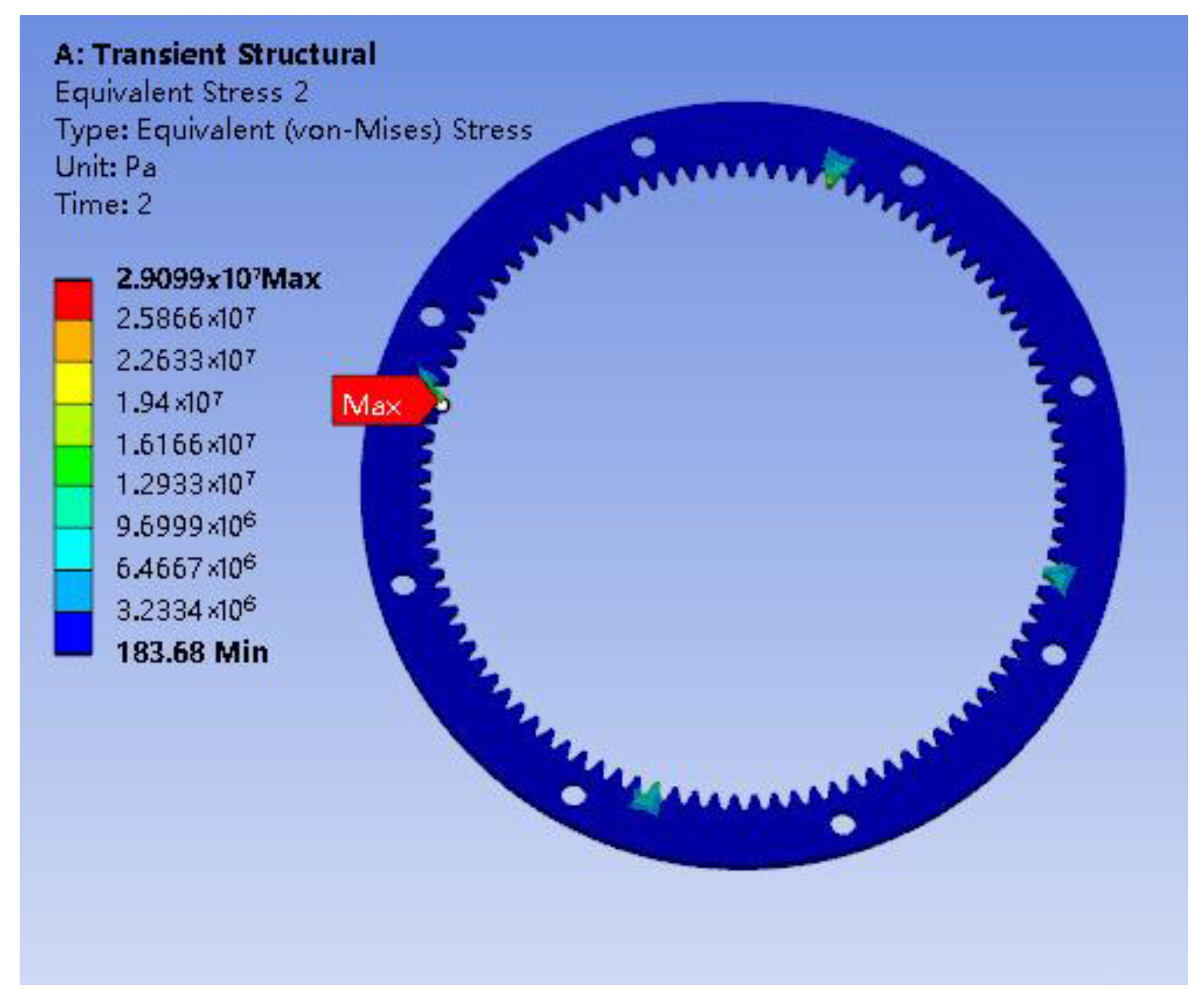
3.3. Digital Twin Model Correction Method
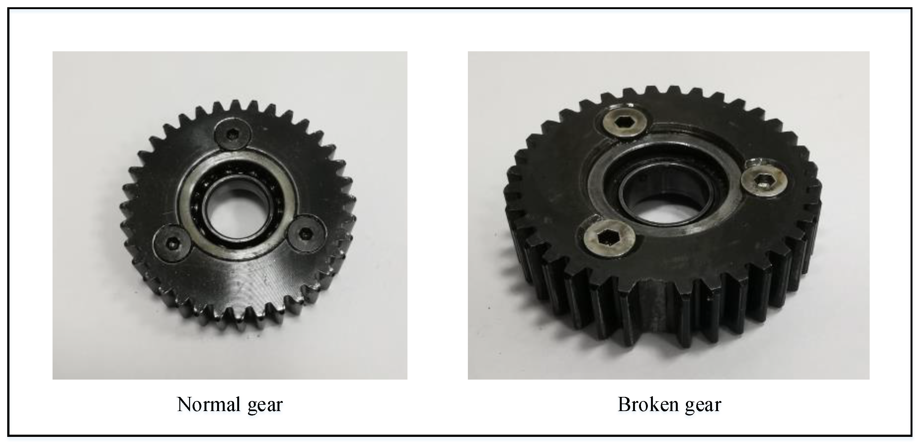
The digital twin model was corrected repeatedly to improve fault detection and visualize the operating state of the wind turbine’s planetary gear. The model was updated when a fault was detected in the planetary gear, and the fault position was highlighted. A flashing light attracted the staff’s attention so that a timely repair and maintenance of the faulty parts of the gearbox could be performed. The data were sent to the digital twin’s database to update the fault diagnosis model. When the planetary gear operated normally, the virtual model continued to operate normally, and the data were stored in the database.

4. Case Study

4.1. Experimental Process

This paper uses a Spectra Quest custom-manufactured wind turbine drive system fault diagnosis test stand as an example. It consists of a motor, spur gear, planetary gear, magnetic powder brake, console (PC), sensor, and acquisition device (STM32 development board). The parameters of the strain gauge sensor are shown in Table 1. In this paper, a wind turbine’s planetary gear fault diagnosis system based on a digital twin is tested by the planetary gear’s normal and broken tooth fault states. The normal and faulty gears used for replacement are the planetary gear of the planetary reduction box, as shown in Figure 11, and the parameters of each gear option are shown in Table 2. For more relevant work of the real wind turbine speed, according to the characteristics of the wind turbine, the spindle speed was low, the motor speed was set to 750 r/min, the frequency was set to 12.5 Hz, the impeller in the spindle speed was just about 18 r/min, the torque was set to 33 N·m, and the sampling frequency for the experiment was 500 Hz. Using Ansys simulation software, through the transient simulation analysis (sun wheel speed 87 RPM, planet carrier torque 33 N·m), as shown in Figure 12, it can be observed that the strain gauge sensors pasted outside the planetary gear ring gear, meshing gear, and tooth root area can be measured with the maximum strain signal. Hence, the planetary gear sensor layout’s wind machine is shown in Figure 13.
First, the strain gauge sensor is connected to the STM32 development board. The other end of the development board is connected to the signal amplifier to amplify and filter the received signals. The other end of the bridge is connected to a PC to realize the real-time acquisition of various data of the wind turbine’s planetary gear. The visualization of the collected data is completed by an ECharts chart, and the collected data are stored in the MySQL database. Then, the classification diagnosis of real-time data and the continuous updating optimization of the fault diagnosis model are realized by a machine learning algorithm supported by MATLAB software. Finally, the User Interface (UI) interface is established in the Unity3D platform, and the diagnostic results and data are displayed visually in the interface.

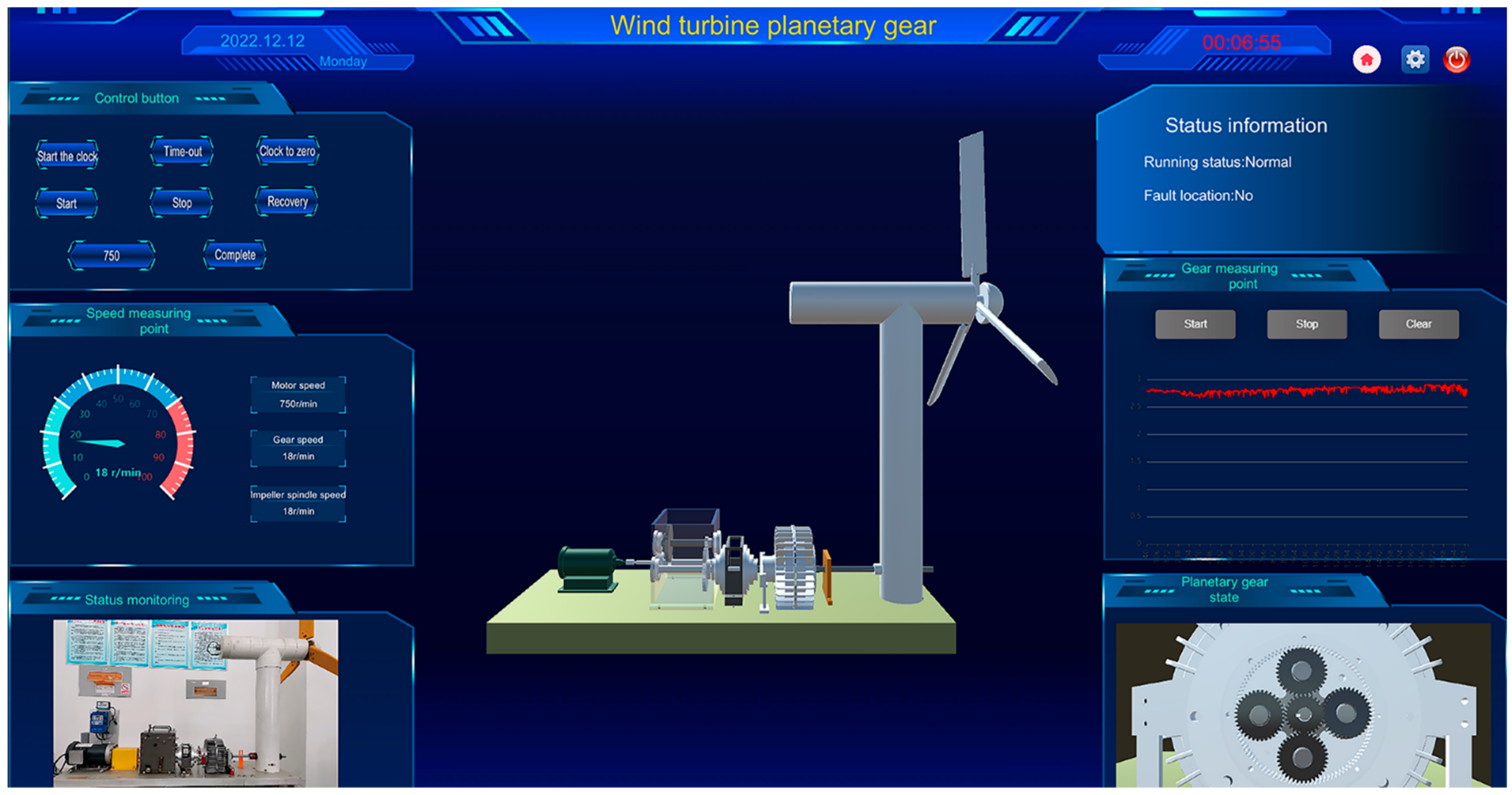
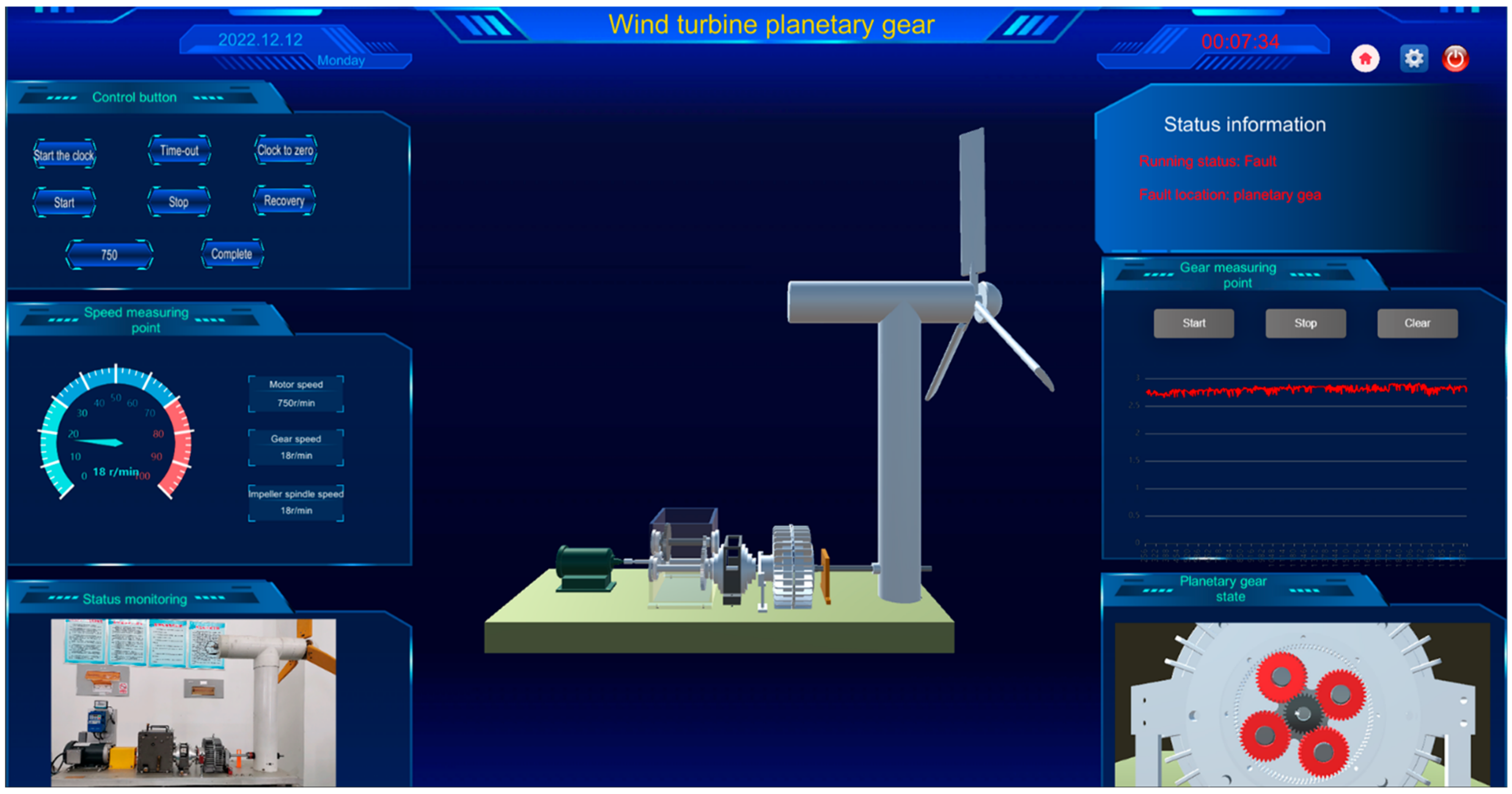
4.2. Digital Twin Visual Interface

First, the digital twin virtual model of the wind turbine transmission system is constructed based on the fault diagnosis experimental platform of the wind turbine transmission system. Then, the operation data of the wind turbine transmission system are collected and sent to the monitoring platform in Unity3D through the UART serial port. The platform functional area of the wind turbine digital twin system consists of six parts: the control button, speed measuring point, state monitoring, state information, gear measuring point, and gearbox state, as shown in Figure 14. In the column of the control button in the upper left corner, the speed of the spindle and motor of the wind turbine is updated based on the collected real-time data, simulates the real-time running state of the wind turbine, and is corrected in the Unity3D platform. When there is a deviation between virtual and real running, users can set and adjust the speed of the virtual model in the digital space both manually and timely according to the real running speed of the physical entity. At the same time, the system can realize the timing of data acquisition and model restoration. The speed measuring point marks the speed of the motor, gear, and blade according to the feedback data of the Hall sensor so that users can receive the information faster. The state monitoring part is connected with external camera devices such as mobile phones to realize the real-time monitoring of the failure test platform in the real world, allowing users to observe the state of physical entities while sitting in front of the system. The trained fault recognition model was invoked in the Unity3D platform as a dynamic link library using C# language. The planetary gear was diagnosed and predicted through the collected real-time signal data. The status information bar displayed the feedback results after diagnosis and prediction. In the part of the gear measuring point, the frequency domain data of the gear root of the outer gear ring of the planetary gearbox measured by the strain gauge sensor are displayed in the system platform using the ECharts chart. Furthermore, the collected data are saved to the MySQL database. When the staff needs to analyze the historical data or retrain the fault identification model, it can be directly retrieved from the database. The gearbox status information section observes the operation of the planetary gear. When the faulty gear data are collected, the system will diagnose and predict the failure of the planetary gear. The status information section on the upper right side of the system interface will mark abnormal conditions and flash red as a warning, enabling users to find fault states more directly, as shown in Figure 15. If the fault diagnosis result is not accurate or cannot be identified, the fault recognition model is retrained by retrieving historical data to realize the continuous updating and optimization of the planetary gear fault diagnosis system of wind turbines based on digital twin.

5. Discussion

This paper applies digital twinning technology to the real-time condition monitoring and fault diagnosis of wind turbine planetary gear. In the monitoring and diagnosing planetary gear of wind turbines, the shortcomings of traditional monitoring and diagnosis systems lacking 3D visualization and online real-time diagnosis are solved. This study aims to establish a digital twin fault diagnosis system by integrating the digital twin model and EMD-ASO-SVM fault diagnosis model to realize the condition monitoring and real-time diagnosis of planetary gear of wind turbines. The feasibility of the digital twin system and the accuracy of fault diagnosis are observed in experimental examples. The results show that, compared with the traditional monitoring and diagnosis system, the proposed method can realize the fault diagnosis and 3D visual monitoring of the planetary gear of wind turbines, more intuitively reflect the operating status and data changes of the equipment, quickly locate the fault location, shorten the equipment maintenance time, and improve the economic benefits. Moreover, experiments show that the diagnostic accuracy of the EMD-ASO-SVM diagnosis model is 94%, which is 6.67% higher than that of the traditional SVM fault diagnosis model. Moreover, the advantages of a small sample size and short time highlight the diagnostic efficiency of the system. Meanwhile, compared with the traditional digital twinning system, the proposed method has the characteristics of low delay and high universality. In future studies, the proposed method may facilitate the study of digital twin fault diagnosis systems for more wind turbine components to complete the comprehensive monitoring of wind turbine operating conditions and online fault diagnosis.

6. Conclusions

This paper proposes a fault diagnosis method for the planetary gear of wind turbines based on digital twinning. Additionally, a fault diagnosis system platform for the planetary gear of wind turbines based on digital twinning is built. The accuracy and feasibility of the proposed fault diagnosis system are verified by the experimental research on the wind turbine fault test bench conducted within the laboratory. The planetary gear fault diagnosis of wind turbines based on a digital twin is realized. The main conclusions are as follows:
(1)
Digital twinning technology is applied to carry out the real-time visual monitoring of the operating state of the wind turbine planetary gear through the data acquisition of sensors, making it possible to monitor the internal operation process of the wind turbine digitally. The proposed digital twin fault diagnosis system provides a new concept and a complete solution for the visual monitoring, real-time fault diagnosis, and performance maintenance of the planetary gear of wind turbines.
(2)
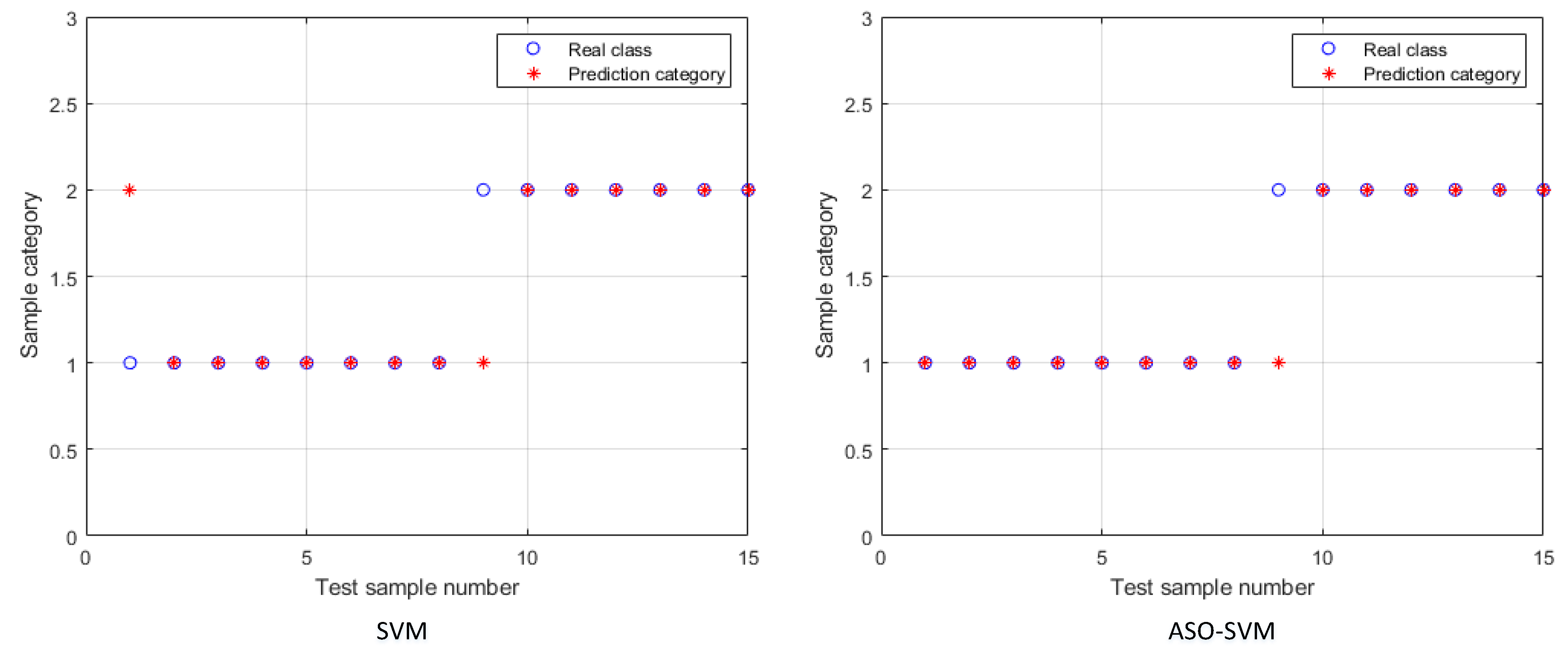
A data-driven fault diagnosis method based on EMD-ASO-SVM is proposed to make timely and effective judgments on the health status of planetary gears by the real-time collection, diagnosis, and analysis of strain signals in the running state of planetary gears of wind turbines. The fault classification accuracy of the ASO-SVM model is 94%, while that of the traditional SVM model is only 86.67%, characterized by fewer required samples and higher diagnostic efficiency.
(3)
Compared with other digital twin systems, the system developed in this paper has the advantages of low delay and high efficiency, providing it with very high application universality.
The research work after this paper will be devoted to introducing more data types to realize the continuous improvement and optimization of the service function of the wind turbine fault diagnosis system based on digital twinning.

Author Contributions

Conceptualization: Y.W. and L.L.; methodology, Y.W.; software, Y.W.; validation, Y.W. and S.B.; formal analysis, Y.W.; investigation, Y.W.; resources, W.S.; data curation, Y.W. and B.W.; writing—original draft preparation, Y.W.; writing—review and editing, Y.W.; visualization, Y.W. and S.B.; supervision, W.S.; project administration, Y.W. and R.J.; funding acquisition, W.S. All authors have read and agreed to the published version of the manuscript.

Funding

This research was supported by Demonstration of Key Technologies of Digital Twinning for Wind Power Equipment Based on Industrial Big Data (Grant number: 202112142).

Institutional Review Board Statement

Not applicable.

Informed Consent Statement

Not applicable.

Data Availability Statement

Not applicable.

Acknowledgments

The authors would like to thank Xinjiang University of Technology, Xinjiang, China, for their support throughout the research project.

Conflicts of Interest

The authors declare no conflict of interest.

References

  1. Lebranchu, A.; Charbonnier, S.; Bérenguer, C.; Prévost, F. A combined mono- and multi-turbine approach for fault indicator synthesis and wind turbine monitoring using SCADA data. ISA Trans. 2019, 87, 272–281. [Google Scholar] [CrossRef]
  2. Xu, Z.; Li, C.; Yang, Y. Fault diagnosis of rolling bearings using an improved multi-scale convolutional neural network with feature attention mechanism. ISA Trans. 2021, 110, 379–393. [Google Scholar] [CrossRef] [PubMed]
  3. Wei, Y.; Yang, Y.; Xu, M.; Huang, W. Intelligent fault diagnosis of planetary gearbox based on refined composite hierarchical fuzzy entropy and random forest. ISA Trans. 2021, 109, 340–351. [Google Scholar] [CrossRef] [PubMed]
  4. Xian, G.-M.; Zeng, B.-Q. Corrigendum: Corrigendum to “An intelligent fault diagnosis method based on wavelet packet analysis and hybrid support vector machines” [Expert Systems with Applications 36 (10)(2009) 12131–12136]. Expert Syst. Appl. Int. J. 2010, 37, 4721. [Google Scholar] [CrossRef]
  5. Salameh, J.P.; Cauet, S.; Etien, E.; Sakout, A.; Rambault, L. Gearbox condition monitoring in wind turbines: A review. Mech. Syst. Signal Process. 2018, 111, 251–264. [Google Scholar] [CrossRef]
  6. Zhao, Z.; Liu, P.X.; Gao, J. Model-based fault diagnosis methods for systems with stochastic process—A survey. Neurocomputing 2022, 513, 137–152. [Google Scholar] [CrossRef]
  7. Farid, M.; Solav, D. Data-driven sensor placement optimization for accurate and early prediction of stochastic complex systems. J. Sound Vib. 2023, 543, 117317. [Google Scholar] [CrossRef]
  8. Liu, L.; Liu, J.; Zhou, Q.; Huang, D. Machine learning algorithm selection for windage alteration fault diagnosis of mine ventilation system. Adv. Eng. Inform. 2022, 53, 101666. [Google Scholar] [CrossRef]
  9. Xu, Y.; Li, Z.; Wang, S.; Li, W.; Sarkodie-Gyan, T.; Feng, S. A hybrid deep-learning model for fault diagnosis of rolling bearings. Measurement 2021, 169, 108502. [Google Scholar] [CrossRef]
  10. Ye, M.; Yan, X.; Chen, N.; Jia, M. Intelligent fault diagnosis of rolling bearing using variational mode extraction and improved one-dimensional convolutional neural network. Appl. Acoust. 2023, 202, 109143. [Google Scholar] [CrossRef]
  11. Abdul, Z.K.; Al-Talabani, A.K.; Ramadan, D.O. A hybrid temporal feature for gear fault diagnosis using the long short term memory. IEEE Sens. J. 2020, 20, 14444–14452. [Google Scholar] [CrossRef]
  12. Yu, J.; Xu, Y.; Liu, K. Planetary gear fault diagnosis using stacked denoising autoencoder and gated recurrent unit neural network under noisy environment and time-varying rotational speed conditions. Meas. Sci. Technol. 2019, 30, 095003. [Google Scholar] [CrossRef]
  13. Grieves, M.; Vickers, J. Digital twin: Mitigating unpredictable, undesirable emergent behavior in complex systems. In Transdisciplinary Perspectives on Complex Systems: New Findings and Approaches; Springer: Cham, Switzerland, 2017; pp. 85–113. [Google Scholar]
  14. Jia, W.; Wang, W.; Zhang, Z. From simple digital twin to complex digital twin Part I: A novel modeling method for multi-scale and multi-scenario digital twin. Adv. Eng. Inform. 2022, 53, 101706. [Google Scholar] [CrossRef]
  15. Tao, F.; Liu, W.; Zhang, M. Digital twin five-dimensional model and ten major applications. Comput. Integr. Manuf. Syst. 2019, 25, 5–22. [Google Scholar]
  16. Liu, Y.; Ren, H. Acquisition method of evaluation stress for the digital twin model of ship monitoring structure. Appl. Ocean Res. 2022, 129, 103368. [Google Scholar] [CrossRef]
  17. Li, J.; Wang, S.; Yang, J.; Zhang, H.; Zhao, H. A Digital Twin-Based State Monitoring Method of Gear Test Bench. Appl. Sci. 2023, 13, 3291. [Google Scholar] [CrossRef]
  18. Zong, X.; Luan, Y.; Wang, H.; Li, S. A multi-robot monitoring system based on digital twin. Procedia Comput. Sci. 2021, 183, 94–99. [Google Scholar] [CrossRef]
  19. Zhang, Y.; Ji, J.; Ren, Z.; Ni, Q.; Gu, F.; Feng, K.; Yu, K.; Ge, J.; Lei, Z.; Liu, Z. Digital twin-driven partial domain adaptation network for intelligent fault diagnosis of rolling bearing. Reliab. Eng. Syst. Saf. 2023, 234, 109186. [Google Scholar] [CrossRef]
  20. Xiong, J.; Ye, H.; Pei, W.; Kong, L.; Huo, Q.; Han, Y. A monitoring and diagnostics method based on FPGA-digital twin for power electronic transformer. Electr. Power Syst. Res. 2022, 210, 108111. [Google Scholar] [CrossRef]
  21. Guo, K.; Wan, X.; Liu, L.; Gao, Z.; Yang, M. Fault diagnosis of intelligent production line based on digital twin and improved random forest. Appl. Sci. 2021, 11, 7733. [Google Scholar] [CrossRef]
  22. Shangguan, D.; Chen, L.; Ding, J. A digital twin-based approach for the fault diagnosis and health monitoring of a complex satellite system. Symmetry 2020, 12, 1307. [Google Scholar] [CrossRef]
  23. Zhang, H.; Qi, Q.; Ji, W.; Tao, F. An update method for digital twin multi-dimension models. Robot. Comput.-Integr. Manuf. 2023, 80, 102481. [Google Scholar] [CrossRef]
  24. Zhang, Q.; Wei, Y.; Liu, Z.; Duan, J.; Qin, J. A Framework for Service-Oriented Digital Twin Systems for Discrete Workshops and Its Practical Case Study. Systems 2023, 11, 156. [Google Scholar] [CrossRef]
  25. Sharma, A.; Kosasih, E.; Zhang, J.; Brintrup, A.; Calinescu, A. Digital twins: State of the art theory and practice, challenges, and open research questions. J. Ind. Inf. Integr. 2022, 30, 100383. [Google Scholar] [CrossRef]
  26. El Bazi, N.; Mabrouki, M.; Laayati, O.; Ouhabi, N.; El Hadraoui, H.; Hammouch, F.-E.; Chebak, A. Generic Multi-Layered Digital-Twin-Framework-Enabled Asset Lifecycle Management for the Sustainable Mining Industry. Sustainability 2023, 15, 3470. [Google Scholar] [CrossRef]
  27. Huang, N.E.; Shen, Z.; Long, S.R.; Wu, M.C.; Shih, H.H.; Zheng, Q.; Yen, N.-C.; Tung, C.C.; Liu, H.H. The empirical mode decomposition and the Hilbert spectrum for nonlinear and non-stationary time series analysis. Proc. R. Soc. Lond. Ser. A Math. Phys. Eng. Sci. 1998, 454, 903–995. [Google Scholar] [CrossRef]
  28. Zhou, C.; Xiong, Z.; Bai, H.; Xing, L.; Jia, Y.; Yuan, X. Parameter-Adaptive TVF-EMD Feature Extraction Method Based on Improved GOA. Sensors 2022, 22, 7195. [Google Scholar] [CrossRef] [PubMed]
  29. Yin, Z.; Hou, J. Recent advances on SVM based fault diagnosis and process monitoring in complicated industrial processes. Neurocomputing 2016, 174, 643–650. [Google Scholar] [CrossRef]
  30. Hua, L.; Zhang, C.; Peng, T.; Ji, C.; Nazir, M.S. Integrated framework of extreme learning machine (ELM) based on improved atom search optimization for short-term wind speed prediction. Energy Convers. Manag. 2022, 252, 115102. [Google Scholar] [CrossRef]
  31. Mohapatra, S.K.; Patnaik, S. ESA-ASO: An enhanced search ability based atom search optimization algorithm for epileptic seizure detection. Meas. Sens. 2022, 24, 100519. [Google Scholar] [CrossRef]
Figure 1. Architecture of the digital twin model.
Applsci 13 04776 g001
Figure 2. Structure of the wind turbine transmission system.
Applsci 13 04776 g002
Figure 3. Establishment of the digital twin model of the wind turbine drive system.
Applsci 13 04776 g003
Figure 4. Data components of the wind turbine drive system.
Applsci 13 04776 g004
Figure 5. Architecture of the digital twin of the wind turbine drive system.
Applsci 13 04776 g005
Figure 6. Intelligent diagnosis process for planetary gear of wind turbine.
Applsci 13 04776 g006
Figure 7. Recognition process of feature extractor based on IMF energy.
Applsci 13 04776 g007
Figure 8. Top 6 IMF components.
Applsci 13 04776 g008
Figure 9. EMD-ASO-SVM algorithm implementation flow chart.
Applsci 13 04776 g009
Figure 10. Fault diagnosis classification result.
Applsci 13 04776 g010
Figure 11. Experiment with planetary gears in different states.
Applsci 13 04776 g011
Figure 12. Equivalent stress nephogram.
Applsci 13 04776 g012
Figure 13. Measuring point layout.
Applsci 13 04776 g013
Figure 14. Digital twin system diagram.
Applsci 13 04776 g014
Figure 15. Fault diagnosis effect diagram.
Applsci 13 04776 g015
Table 1. Strain gauge sensor parameters.
TypeGrid Size (mm)Base Size (mm)Resistance Value (Ω)
350-3AA3.0 × 3.17.3 × 4.1350 ± 0.1
Table 2. Gear main parameters and geometric dimensions.
ItemsGear
Number of teeth36
Module (mm)1
Pressure Angle20
Crest height (mm)1
Top clearance (mm)0.25
Root height (mm)1.25
Tooth height (mm)2.25
Diameter of the dividing circle (mm)36
Base circle diameter (mm)33.83
Apex diameter (mm)38
Root circle diameter (mm)33.5
Pitch of teeth (mm)3.14
Tooth thickness (mm)1.57
Slot width (mm)1.57
Disclaimer/Publisher’s Note: The statements, opinions and data contained in all publications are solely those of the individual author(s) and contributor(s) and not of MDPI and/or the editor(s). MDPI and/or the editor(s) disclaim responsibility for any injury to people or property resulting from any ideas, methods, instructions or products referred to in the content.

