Article

A Simple Neural-Network-Based Decoder for Short Binary Linear Block Codes

1
Department Electrical Engineering, National Kaohsiung University of Science and Technology, Kaohsiung 807618, Taiwan
2
Department Electronic Engineering, National Kaohsiung University of Science and Technology, Kaohsiung 807618, Taiwan
*
Author to whom correspondence should be addressed.
Appl. Sci. 2023, 13(7), 4371; https://doi.org/10.3390/app13074371
Submission received: 4 February 2023 / Revised: 22 March 2023 / Accepted: 27 March 2023 / Published: 29 March 2023

Abstract

:
The conventional soft decision decoding (SDD) methods require various hard decision decoders (HDDs) based on different codes or re-manipulate the generator matrix by the complicated Gaussian elimination technique according to the bit reliability. This paper presents a general multi-class neural network (NN)-based decoder for the short linear block codes, where no HDD and Gaussian elimination are required once the NN is constructed. This network architecture performs multi-classification to select the messages with high occurrence probabilities and chooses the best codeword on a maximum likelihood basis. Simulation results show that the developed approach outperforms the existing deep neural network (DNN)-based decoders in terms of decoding time and bit error rate (BER). The error-correcting performance is also superior to the conventional Chase-II algorithm and is close to the ordered statistics decoding (OSD) in most cases. For Bose–Chaudhuri–Hocquenghem (BCH) codes, the SNR is improved by 1dB to 4dB as the BER is 10−4. For the (23, 12) quadratic residue (QR) code, the SNR is improved by 2dB when the BER is 10−3. The developed NN-based decoder is quite general and applicable to various short linear block codes with good BER performance.

1. Introduction

The study of the application on neural networks to error correction codes has been ongoing since the late 1980s [1,2,3,4,5,6,7,8,9]. However, at that time, hardware technology needed to be more capable of efficiently training and implementing sizable neural network (NN) models, which limited the number of network layers and performance. The training results thus often did not reach the desired bit error rate. In recent years, advances in hardware technology have made it possible to train and implement more extensive and complex NN models, leading to significant progress in this field. The use of deep learning for error correction codes has become more popular in recent years due to the rise of deep learning (DL) and the availability of hardware acceleration. The NNs for decoding are typically divided into two main categories: binary classification and noise elimination architectures. The binary classification architecture is designed to classify the input data into two categories, such as “correct” and “incorrect,” while the noise elimination architecture aims to remove noise from the input data to improve the decoding accuracy. Both approaches have effectively improved the performance of error correction codes and are an active area of research.
Several soft decision decoding (SDD) methods are commonly used in error correction codes. These include the belief propagation (BP) algorithm [10], which uses an iterative method to eliminate noise in the input signal, and the Chase-II algorithm [11], which uses enumeration to select candidate codewords obtained by the hard decision decoder (HDD). Another popular method is the ordered statistics decoding (OSD) method [12], which reconstructs the generator matrix of the code based on the bit reliability to produce the possible candidate message. The candidate codewords are finally selected from the perspective of the maximum likelihood. Traditional SDD decoding methods often require significant time and computing resources, as they rely on iterative, enumerative, and sorting processes.
In contrast to conventional SDD methods, the DL-based methods require only matrix multiplication to obtain a solution as the NN or deep neural network (DNN) is trained. This method greatly simplifies the calculation process, and hardware-accelerated technology can be used to perform parallelized calculations, significantly reducing the time required for error correction. In addition, the DL-based methods can learn and adapt to various codes. These advantages make the DL-based method an attractive alternative to traditional methods. The DNN-based decoder presented in [13] eliminated the problem of overfitting to the training codeword set by using the syndrome and channel reliabilities as the input of the network. This framework makes the NN focus on the noise estimation. In [14], a novel DNN-based denoiser was presented, which directly learns the mapping from a noisy codeword to its corresponding denoised one. Results showed that the effectiveness of the denoiser is significant.
Authors in [5] proposed the DNN-based belief propagation flip (BPF) decoder for polar codes. The idea is to deploy a DNN to decide which bits to flip. In [7], the convolutional neural network (CNN) model is employed for decoding polar codes to reduce the delay and efficiency. Lu et al. [8] introduced a simplified metric derived from the path metric domain and designed a custom-tailored DNN to enhance its efficiency when the successive cancelation list (SCL) decoder is adopted. Simulation results indicated that such a metric incurs almost no performance loss but with lower computational complexity.
In [6], a model-driven DL decoder for irregular binary low-density parity-check (LDPC) codes was invented by the alternating direction method of multipliers (ADMM) technique. Authors in [9] analyzed the problem of the binary cross entropy during the training epochs of the DL-based decoder and introduced the negative bit error rate loss function to improve the decoding performance of the DNN-based decoder.
This paper aims to develop a generalized NN-based decoding architecture for short linear block codes. The specific contributions of this paper are summarized as follows:
(1)
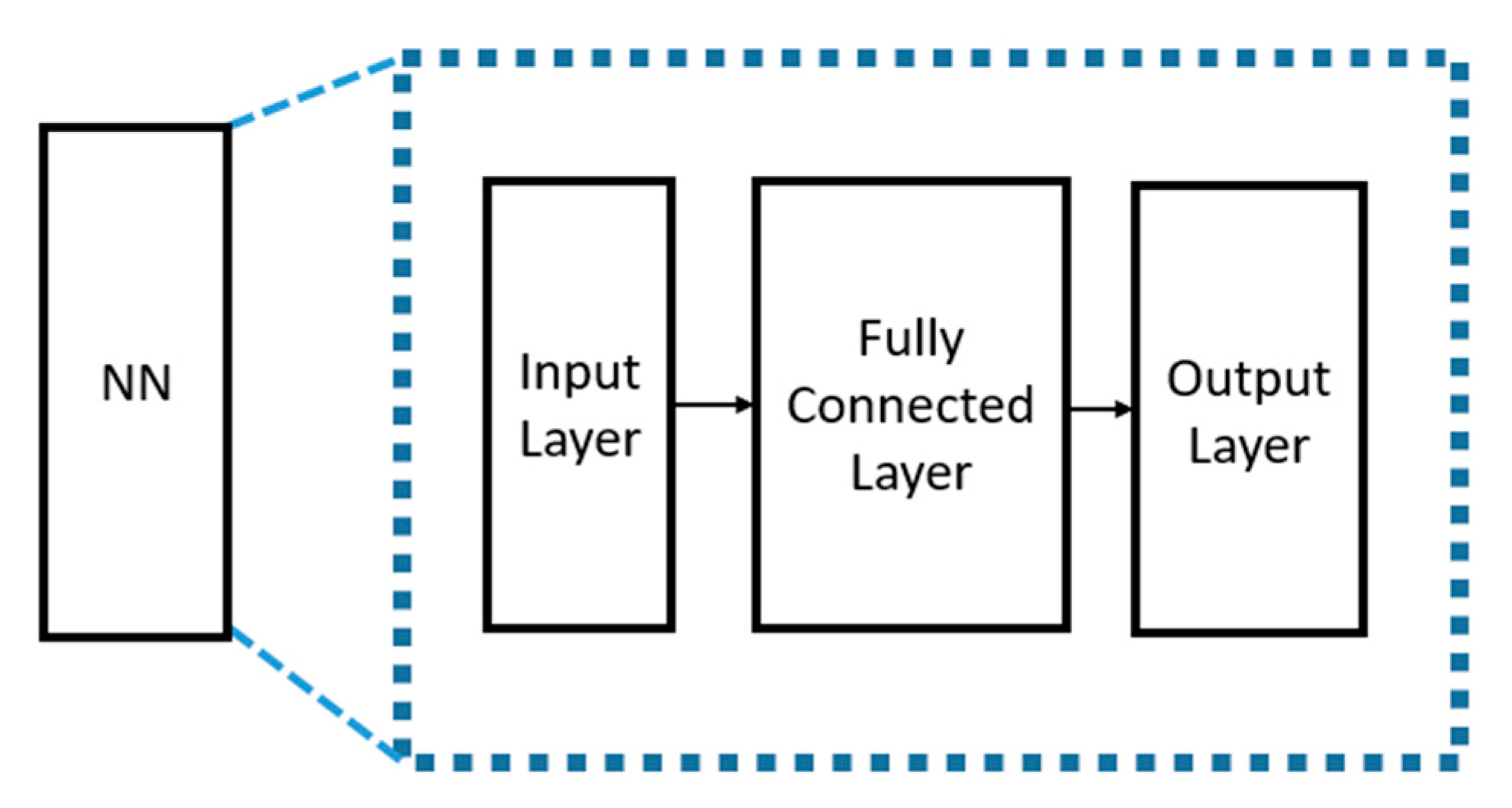
Multi-class NN-based decoding framework is presented, where only the received signal sequence acts as the input and one fully connected layer is required.
(2)
The presented NN-based decoder outperforms the existing syndrome-based DNN decoder and denoiser [13,14] in terms of decoding time and error performance.
(3)
The decoding performance of the proposed decoder is close to the well-known SOD algorithm [12], which requires plenty of candidate codewords for evaluation and is involved in complicated Gaussian elimination.
(4)
The presented multi-class NN-based decoder is general and applicable to different short linear block codes with no additional HDD required as compared to the Chase-type algorithm [11].
The remainder of this paper is organized as follows. Section 2 provides the preliminary of traditional soft decision decoders. The existing syndrome-based DNN decoder and the framework combined the HDD and DNN-based denoiser are discussed in Section 3. Section 4 presents the multi-class NN-based decoder. Section 5 and Section 6 describe the dataset generation and simulation procedure. We make a conclusion in Section 7.

2. Preliminaries of Conventional Soft Decision Decoder

2.1. Message Encoding Process

A message m is represented as m = [m0, m1, …, mk−1], where m ∈ {0, 1}k and k is the number of bits in the message. The polynomial form is expressed as (1):
m x = m k 1 x k 1 + + m 1 x + m 0
The generator polynomial of the code C is
g x = x n k + g n k 1 x n k 1 + + g 1 x + g 0 , g i { 0,1 }
The corresponding generator matrix G is
G = I k | P
where I k is the identity matrix of dimension k and P is the parity sub-matrix (p. 7, [15]).
By (3), the message m is encoded as the codeword
c = m G
in a systematic form, where c = [c0, c1, …, cn−1] and ci ∈ {0, 1}. Here, n is the codeword length. The codeword c can be expressed as (4) in a polynomial form.
c ( x ) = m ( x ) x n k + m ( x ) x n k m o d g ( x )
The codeword c must satisfy
c H T = 0
where H is the parity check matrix, which is defined as follows:
H = [ P T | I n k ]
Here I n k is the identity matrix of dimension nk.
Consider the (n, k, d) binary linear block code, where d is the minimum Hamming distance. The error-correcting capability t is thus
t = d 1 2

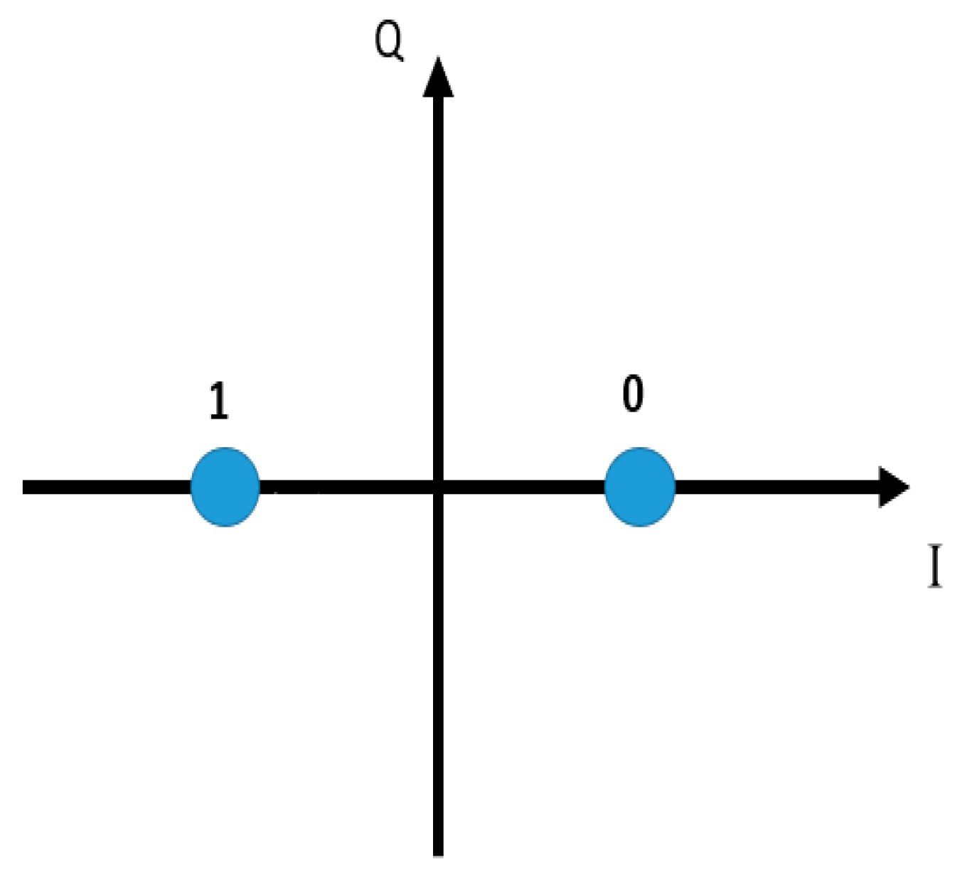
2.2. Data Transmission over Channels

It is assumed that the data is transmitted over all additive white Gaussian noise (AWGN) channels, and the binary phase-shift keying (BPSK) modulation is used for transmission.
The codeword c is transmitted by the BPSK modulation as shown in Figure 1. For the bit ci in the codeword c, the received signal yi by BPSK over the AWGN channel is
y i = 1 2 c i + e i , i = 0,1 , , n 1
where ei represents the white Gaussian noise with variance N0/2.
Let y = [y0, y1, …, yn−1] is the received signal sequence and r = [r0, r1, …, rn−1] be the received word. Because of BPSK signaling, the received word can be determined by
r i = 1 , y i 0 0 , y i > 0 , i = 0,1 , , n 1 .
The absolute log-likelihood ratio for ri is derived as
L r i = l o g p y i c i = 0 p y i c i = 1 = 4 | y i | N 0
The bit reliability is thus defined as | y i | for i = 0, 1, …, n−1.
As the received word r is given, its corresponding syndrome s is calculated as
s = r H T
If s = 0, it is a codeword by (6). Otherwise, it indicates that the errors happen.

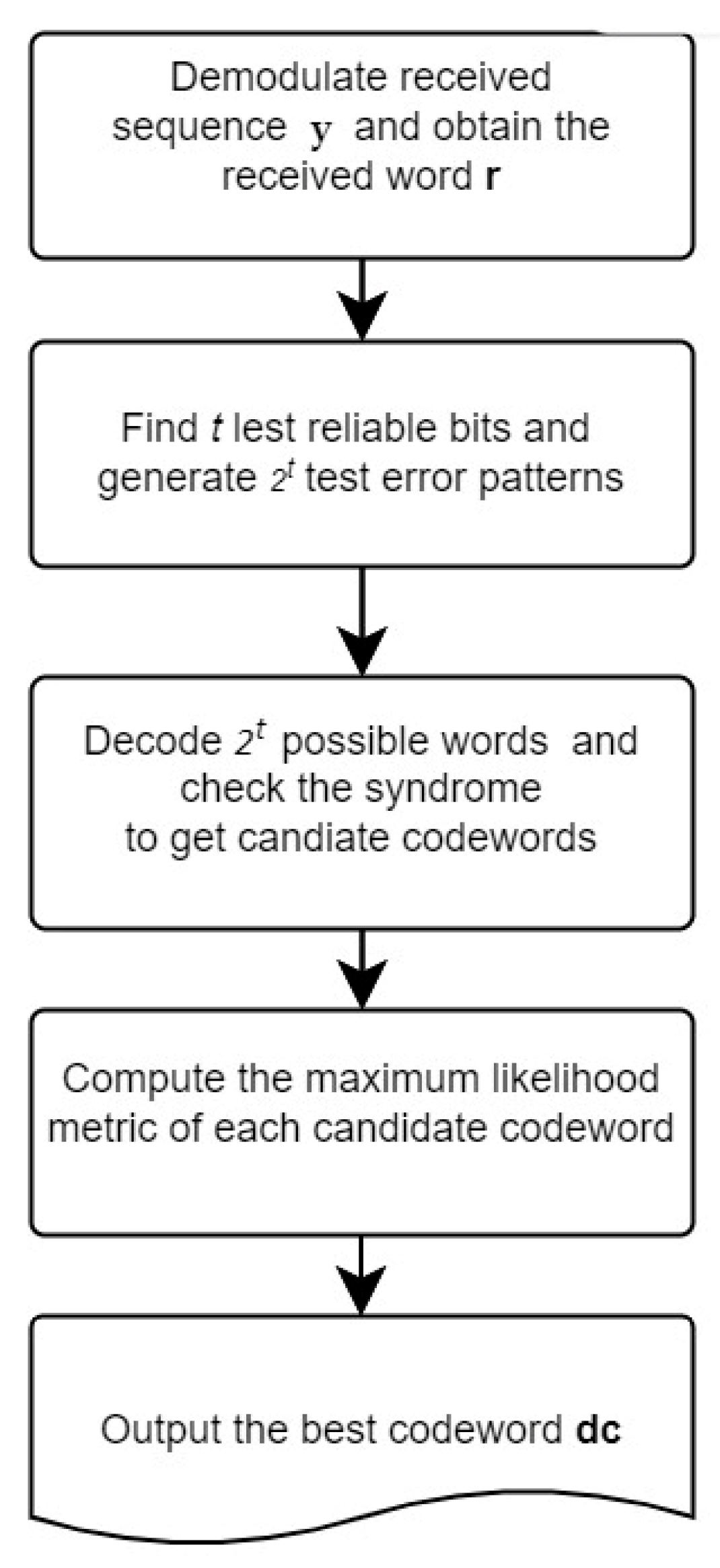
2.3. Chase-II Decoding Algorithm

The Chase-II algorithm [11] generates the test error patterns based on bit reliability | y i | and the error-correcting capability t, and then utilizes the HDD to obtain the candidate codewords. Finally, the best codeword is selected on a maximum likelihood basis. Figure 2 illustrates the procedure of the Chase-II algorithm. The detailed steps are described as follows:
  • Step 1: Obtain the received signal sequence y and demodulate it as the received word r.
  • Step 2: Find the t least reliable bits and generate 2t test error patterns.
  • Step 3: Decode 2t words and check their syndromes. The decoded word with zero syndrome will be viewed as the candidate codeword dr.
  • Step 4: Evaluate D 1 d r = { i | r i = d r i , 0 i n 1 } and compute the maximum likelihood metric i D 1 d r | y i | of the codeword dr.
  • Step 5: Output the best codeword as dc with the minimum value of i D 1 d r | y i | .

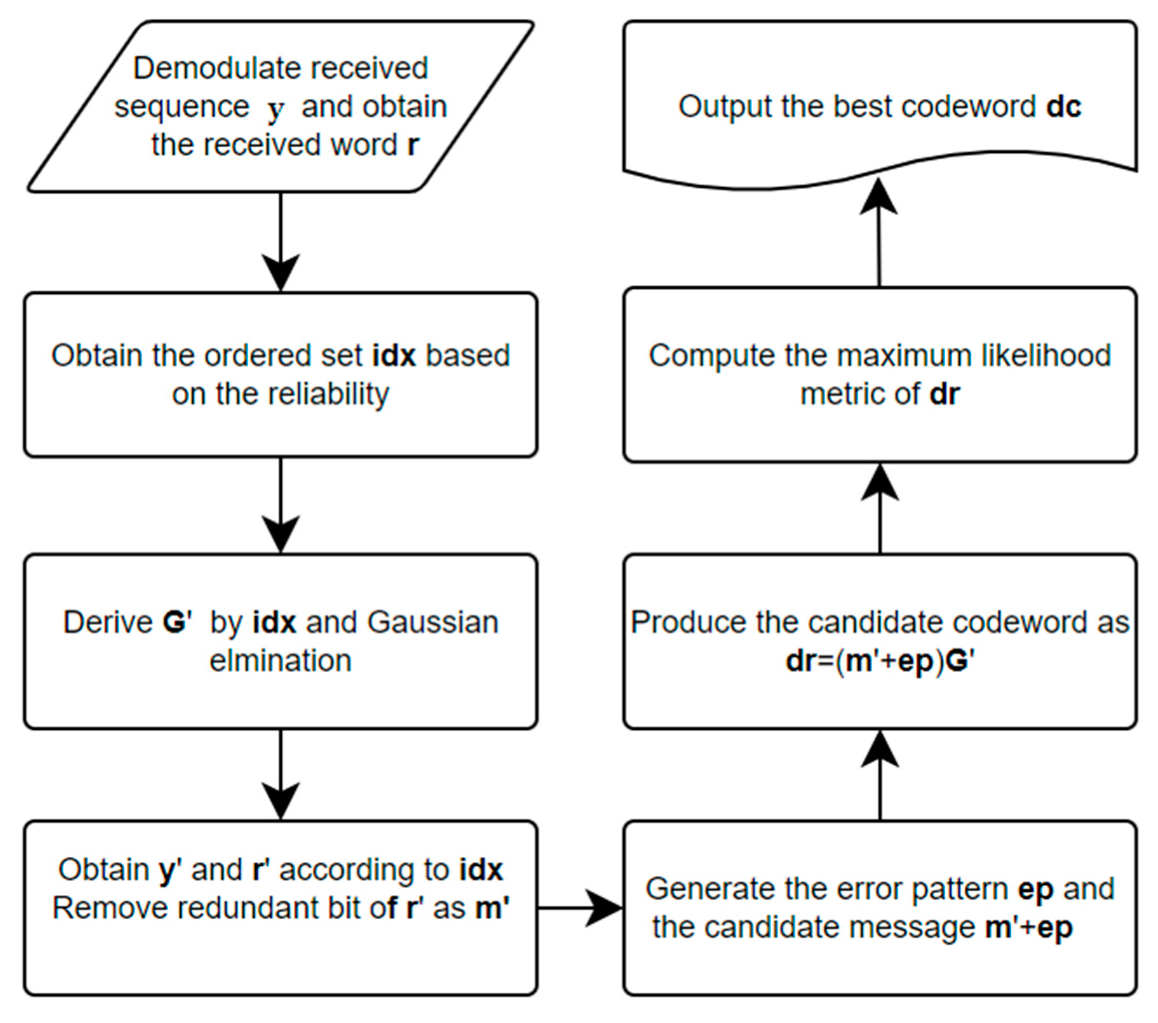
2.4. Ordered Statistics Decoding (OSD)

The ordered statistics decoding algorithm [12] first sorts the received signal sequence based on the bit reliability in a descending order and obtains a permutation. By such a permutation, the new systematic generator matrix will be derived via the sorted generator matrix. The associated received signal sequence and word are obtained. The test error patterns are then generated to produce the possible codewords. Finally, the best codeword is selected on a maximum likelihood basis. Figure 3 illustrates the steps in the OSD approach. Details of OSD(w) are described as follows:
  • Step 1: Obtain the signal sequence y and obtain the ordered index set of reliability idx. i d x = { η 0 , η 1 , , η n 1 } where r η k r η l , for k > l .
  • Step 2: Permute G according to idx and perform Gaussian elimination as a systematic form G = [ I k | P ~ ] . If the form is unavailable, reorder idx based on the reliability.
  • Step 3: Permute y and r as y’ and r’ according idx. Let m be the first k bits of r’.
  • Step 4: Generate the test error patterns e p = [ e p 0 , e p 1 , , e p k 1 ] for m, where the Hamming weight of ep is less than or equal to w. As a result, there are possible i = 0 w k i candidate messages. The candidate codewords dr will be obtained by G’.
  • Step 5: Evaluate D 1 d r = { i | r i = d r i , 0 i n 1 } and compute the maximum likelihood metric i D 1 d r | y i | of the codeword dr
  • Step 6: Output the best codeword as dc with the minimum value of i D 1 d r | y i | .
The Chase-II decoding algorithm is constructed on the HDD, which is invented based on the specific code itself. The plenty of test error patterns will be fed into the HDD iteratively. It also leads to longer decoding time. The OSD method is involved in the huge computation on the Gaussian elimination based on the received signal sequence. As a new signal sequence is received, the OSD decoder will re-sort the bit reliability and perform the Gaussian elimination again. Such an approach is computationally intensive.

3. Deep Learning-Based Decoder

Deep learning-based decoders have recently presented in [13,14,16,17,18]. The key approaches focused on the frameworks of binary classification [13,16,17,18] and denoiser [14]. The approach of binary classification utilizes the DNN to recognize 0 or 1 for each received bit, where the soft information (reliability) is applied. The second one adopts the NN to remove the noise from the received signal, thereby improving the accuracy of the error-correcting process. This framework is a cascade of a denoiser and the conventional HDD.

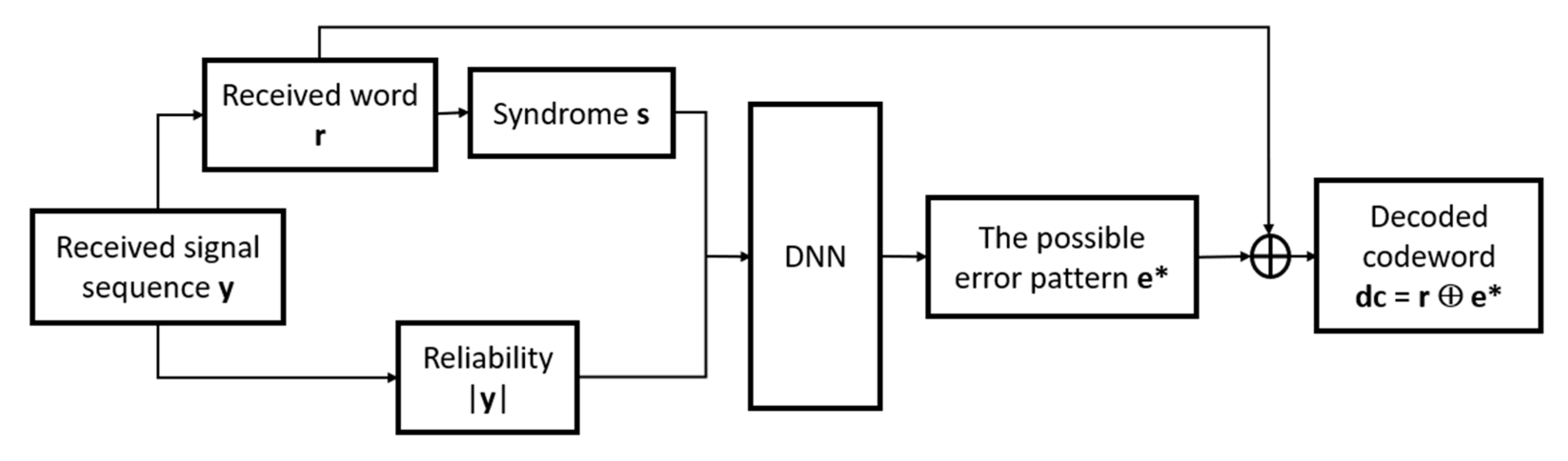
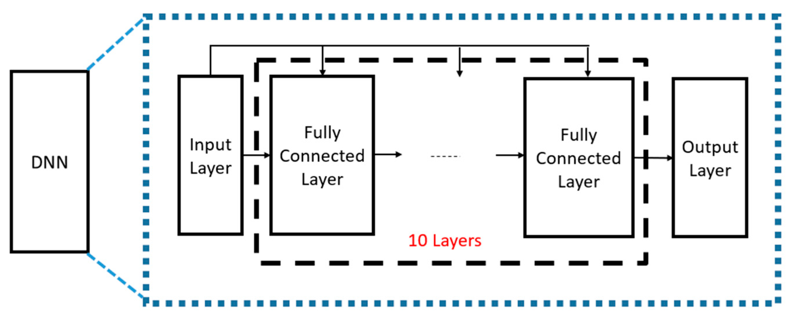
3.1. Soft Decision Decoding Based on DNN-Based Binary Classification

Bennatan and Choukroun [13] developed the binary classification framework for decoding as shown in Figure 4. The main concept of this framework is to use the syndrome and the reliability of the received word as the inputs to train a DNN. The output of the DNN is the possible error pattern. One advantage of this framework is that it takes into account both the syndrome value s and the reliability of the received word |y|, so as to improve the decoding performance. The output is the n-bit error pattern e * = [ e 0 * , e 1 * , , e n 1 * ] , where e i * 0,1 , 0 i n 1 . Each bit e i * is determined by the binary classification of the DNN. As e * is obtained, the decoded codeword is d c = r e * , where is exclusive OR (XOR) operation.
The DNN architecture in [13] is illustrated in Figure 5 It consists of ten fully connected layers and the number of nodes in each layer is determined by the codeword length n. The activation function used in each layer is the rectified linear unit (ReLU) function, except for the output layer, where the sigmoid function is used.

3.2. DNN-Based Denoiser for Soft Decision Decoding

Zhu and Cao [14] presented a new decoding architecture in Figure 6, which uses the DNN as the denoiser. This approach was inspired by the noise removal of image processing [19]. In this architecture, the denoised signal sequence dy is obtained by the DNN and the received word r can be determined based on dy. Finally, the HDD produces the codeword based on r. This architecture combines the DNN-based denoiser and the traditional HDD, resulting in better decoding performance as compared to the HDD only. The DNN architecture [14] in Figure 7 consists of three fully connected layers. The total numbers of nodes in these three layers are 256, 128 and 64, respectively. The activation function used in each layer is the ReLU function.

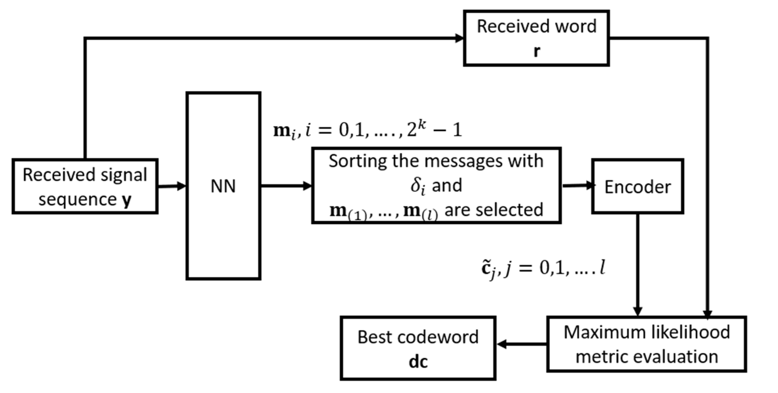
4. Proposed Multi-Class Neural Network-Based Decoder

The proposed multi-class NN-based decoding architecture is depicted in Figure 8 The NN takes the received sequence y to estimate occurrence probabilities of all possible message m i , called δ i , where i = 0,1 ,   . , 2 k 1 and k is the message length. Then, the sorting operation is performed based on the occurrence probability δ i . Let the ordered set of the occurrence probability be Δ { ν 0 , ν 1 ,   , ν 2 k 1 } , where δ ν l δ ν κ , for l κ . m ( i ) is denoted as the message with the occurrence probability δ ν i . The messages of l highest occurrence probabilities, called m ( 1 ) , m 2 ,   , m l , are thus selected. These messages are encoded as the codewords c ~ 1 , c ~ 2 ,   , c ~ l by the generator matrix G. We evaluate D 1 c ~ j = { i | r i = c ~ j , i , 0 i n 1 } and compute the maximum likelihood metric i D 1 c ~ j | y i | of the codeword c ~ j . Finally, the best codeword is selected as dc with the minimum value of i D 1 c ~ j y i , j = 1,2 ,   , l .
The proposed NN is depicted in Figure 9, which includes only one fully connected layer. The related parameters of NN are listed in Table 1. As compared to the framework in [13], the input of the proposed NN architecture includes the received signal sequence only. No syndrome values serve as the input. As the message length k increases, the total numbers of nodes in the fully connected and output layers will exponentially increase with respect to k. The sorting for 2 k elements becomes time-consuming. The proposed NN-based decoder is suitable for the short linear block codes because of message length k.

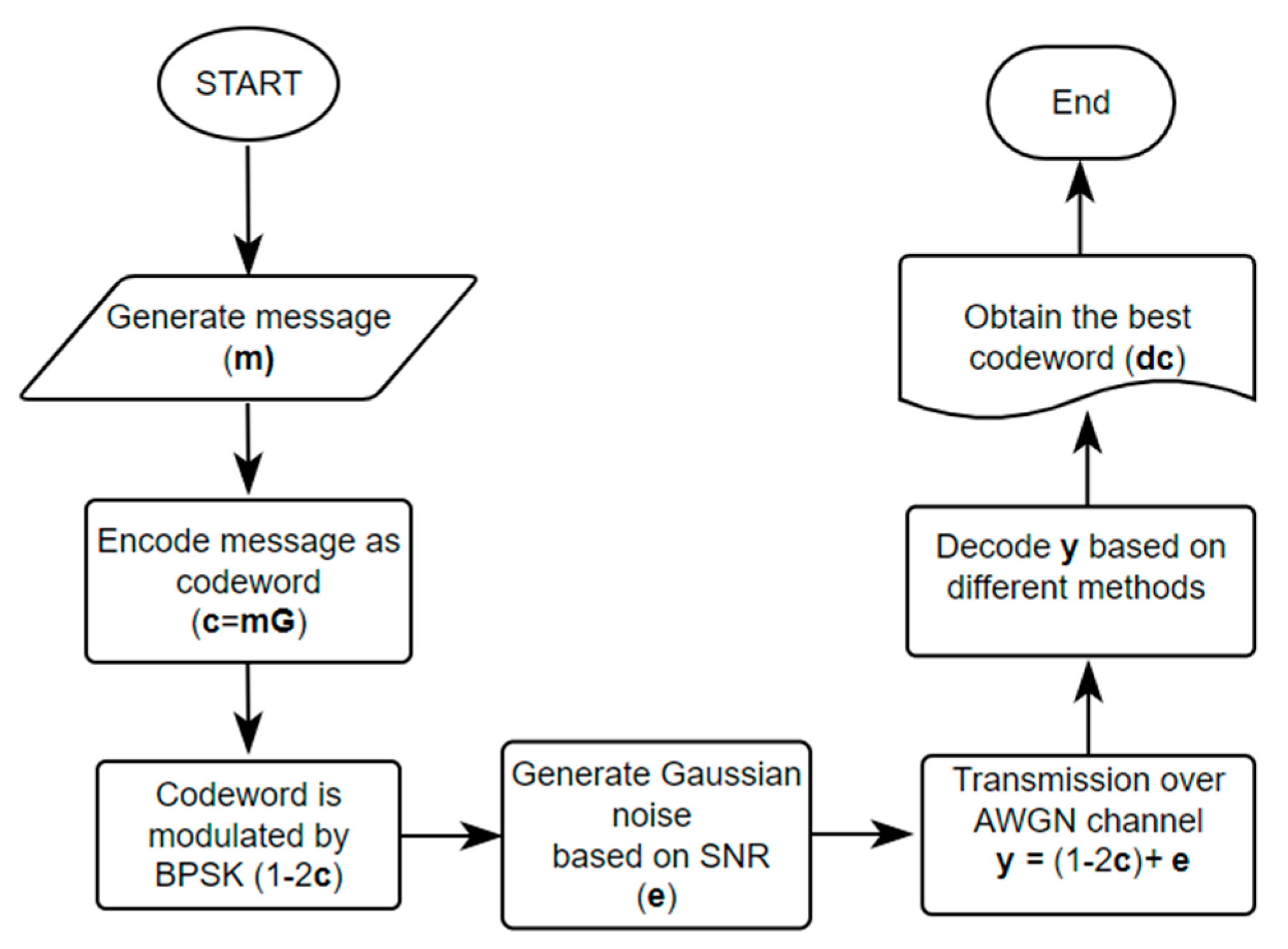
5. Dataset Generation and Neural Network Training

Given a specific signal-to-noise ratio defined in (14), the dataset over the AWGN channel is generated as follows:
  • Randomly generate a message m.
  • Encode m to produce the codeword c.
  • Use BPSK modulation and AWGN to generate the received signal sequence y.
  • Repeat steps 1–4 one million times to produce the dataset.
  • Divide the dataset into the training and validation sets with a ratio of 9:1.
This data generation method for training NN or DNN-based decoding framework is commonly used in [13,14]. However, the total numbers of generated error patterns with different Hamming weights are unbalanced. The error patterns with lower Hamming weight occur more frequently than those with high Hamming weight. Such an uneven distribution of error patterns may lead to a bias in the training of the NN, thereby potentially reducing its performance.
The probability of the weight-j error pattern can be calculated via binomial distribution.
P j = C j n × P e j × ( 1 P e ) n j , 0 j n
where C j n is the number of combinations of n items taken j at a time, P e is the bit error probability, which depends on the SNR. Assume that the bit error probability and codeword length are P e = 0.07 and n = 15 , respectively. The error probabilities for j = 0,1 , 2,3 , 4 can be calculated as follows:
P 0 = C 0 15 × 0.07 0 × 1 0.07 15 = 0.33 P 1 = C 1 15 × 0.07 1 × 1 0.07 14 = 0.38 P 2 = C 2 15 × 0.07 2 × 1 0.07 13 = 0.2 P 3 = C 3 15 × 0.07 3 × 1 0.07 12 = 0.065 P 4 = C 4 15 × 0.07 4 × 1 0.07 11 = 0.014
As observed, the generated codewords with no errors account for 33% of the dataset, those with one error account for 38%, those with two errors account for 20%, and those with more than two errors account for 9%. Although this method is simple, it results in an uneven dataset. Therefore, how to produce a balanced dataset becomes an interesting issue in the future.

5.1. Generation of Received Signal by BPSK over AWGN Channel

Algorithm 1 shows the data generation method for the BPSK-modulated signal over the AWGN channel as the signal-to-noise ratio (SNR) is given. The SNR is defined as
γ 10   log 10 E b N 0
where E b is the energy per bit. When generating the dataset at the various SNR γ , one could set E b as 1 and change the noise variance N 0 . That is,
N 0 = 10 γ 10 2
How to generate the dataset is described in Algorithm 1.
Algorithm 1 Generative Algorithm of Additive White Gaussian Noise
 Input: codeword c, SNR γ
 Output: received signal sequence y
1: Compute N0 by (14)
2: for i = 0, 1, …, n−1 do
3:   Generate Gaussian noise ei N(0, N0/2)
4:   if ci = 1 then
5:    yi= −1 + ei
6:   else
7:    yi= 1 + ei
8:   end if
9: end for
10: return y

5.2. Training of Neural Network

Python 3.8 and TensorFlow 2.5 are used to train the neural network in our simulations. The dataset of 1,000,000 records is divided into a training set of 900,000 and a validation set of 100,000 records, with a ratio of 9:1. During training, the entire training set is trained repeatedly 10 times (epochs = 10), with the weight values being updated once in each batch of 128 data points (batch size = 128). The optimizer used is ADAM [20] with a learning rate of 10−3. The loss function is determined based on the output of the NN. Since the expected output of each node in the output layer is either 0 or 1, the binary cross entropy (BCE) loss function is utilized as shown in (16):
B C E = 1 N b i = 1 N b θ i log θ i ^ + 1 θ i log 1 θ i ^
where N b is the batch size, θ i is the expected output value, and θ i ^ is the output value of NN.

6. Experimental Results of Decoding by Proposed Multi-class NN-Based Decoder

6.1. Simulation Environment and Procedure

Simulations are conducted on the computer with Intel i9-10900 processor and RTX 3080 graphics card. The traditional soft decision decoding methods, including BP, Chase-II, OSD [11,12], and the recent DNN-based decoding approaches [13,14] are evaluated. The BCH and QR codes act as examples for investigation. The simulation procedure for a random message is shown in Figure 10. For each SNR value, 1,000,000 messages are simulated. We consider the decoding performance when the SNR is from 0 to 7 dB. The codeword error rate (CER) and bit error rate (BER) for various decoding methods are assessed.

6.2. Experimental Results

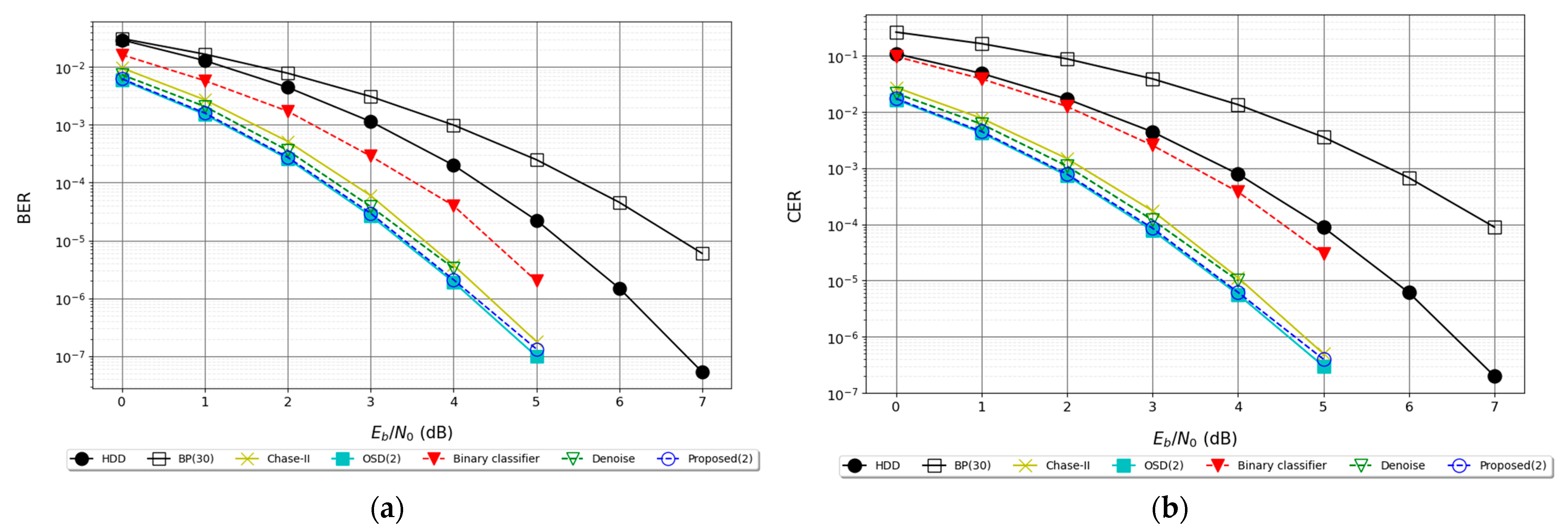
6.2.1. Results for BCH (15, 7) Code

The code length of BCH (15, 7) is n = 15, the message length is k = 7, the error-correcting capability is t = 2 and the code rate is 7/15 = 0.46. As shown in Figure 11a,b, the BER of the proposed decoding framework with l = 2 is better than that of the Chase-II algorithm and approaches that of OSD (w = 2). The numbers of candidate codewords for the proposed method, Chase-II and OSD algorithms are 2, 21 and 121, respectively. Figure 11a,b also reveals that the proposed decoder also outperforms the DNN-based or assisted decoder in [13,14].

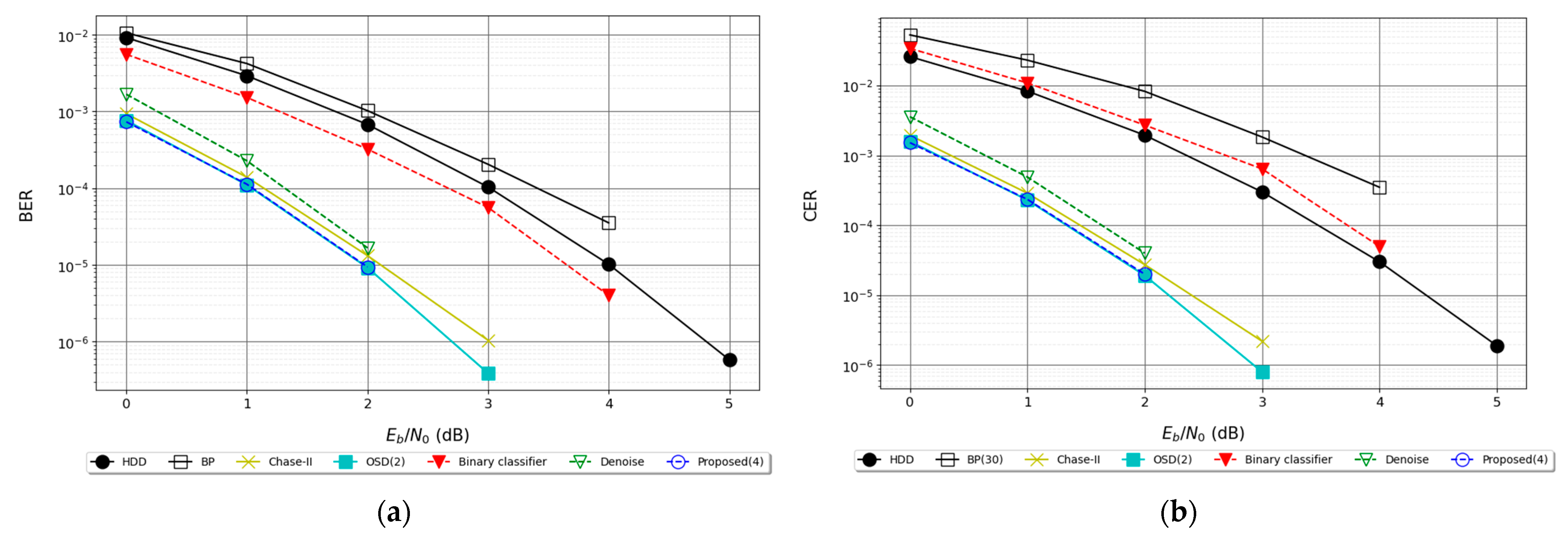
6.2.2. Results for BCH (15, 5)

The code length of BCH (15, 5) code is n = 15, the message length is k = 5, the error correcting capability is t = 3, and its code rate is 5/15 = 0.33. Figure 12a,b shows that the proposed multi-class NN-based approach has almost the same BER and CER performance as the OSD method. For evaluating the maximum likelihood metric, the proposed method, Chase-II and OSD algorithms require 4, 21 and 121 candidate codewords, respectively. The decoding complexity is thus reduced over the conventional methods. It is also observed that the presented NN-based decoder is superior to DNN-based decoder [13] and denoiser [14] in terms of CER and BER.

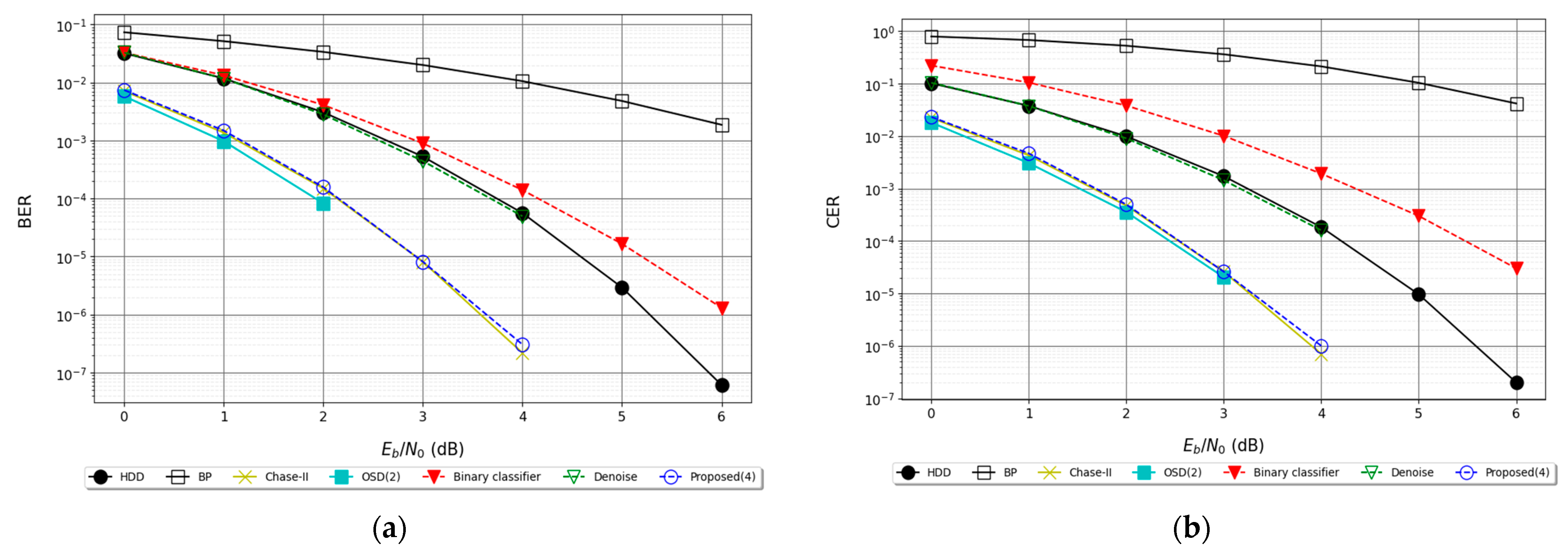
6.2.3. Results for QR (23, 12) Code

The code length of QR (23, 12) code is n = 23, the message length is k = 12, the error correcting capability is t = 3, and the code rate is 12/23 = 0.52. In Figure 13a,b, the performance of the OSD method is slightly better than that of the proposed NN-based approach. The proposed method still outperforms other decoding algorithms. The DNN-based decoder [14] is inferior to HDD both in CER and BER performance. The DNN-based denoiser [13] combined with the HDD obtains no decoding benefits as compared to the HDD itself. When the code length increases, the advantage of the proposed method becomes insignificant.

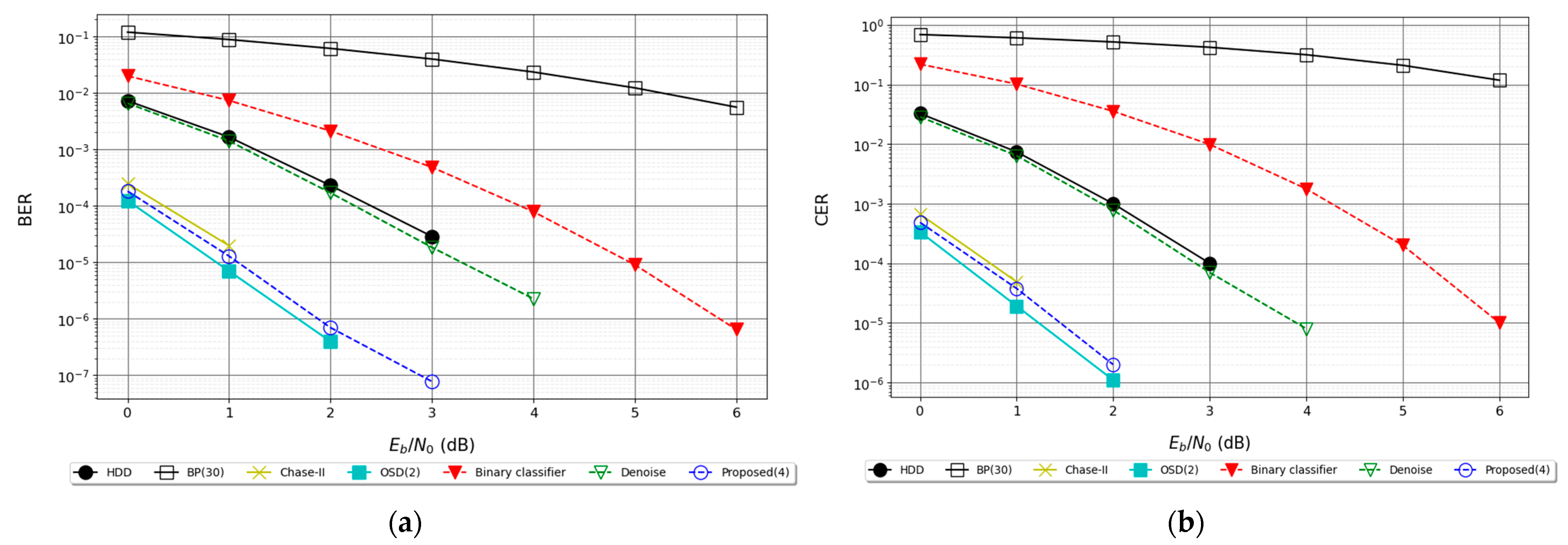
6.2.4. Results for BCH (31, 11) Code

The code length of BCH (31, 11) is n = 31, the message length is k = 11, the error correcting capability is t = 5, and the code rate is 11/31 = 0.35. Figure 14a,b reveals the similar observations as the previous results. The BER and CER performance of the presented NN-based decoder falls between the OSD and Chase II algorithms. Note that only four candidate codewords are evaluated in our method.
The decoding time for different decoding algorithms at the SNR of 0 dB is summarized in Table 2, where the colors of red, green and blue mean the first, second and third minimum decoding time. Here, the HDD utilizes the syndrome-weight decoder. The total number of candidate codewords for BCH (15, 7), BCH (15, 5), BCH (31, 11) and QR (23, 12) codes are 2, 4, 4 and 4, respectively. Results show that the proposed NN-based method is competitive as compared to the other DNN-based frameworks.

7. Conclusions

This paper proposed a generalized multi-class NN-based decoding architecture. Simulation results indicated that the proposed method is superior to other DNN-based decoders reported in the literature [13,14]. For the short linear block codes, the BER and CER performance of the developed method is close to the well-known OSD algorithm and slightly better than the Chase-II algorithm. It also required much less decoding time than the OSD scheme. Such an architecture is highly compatible and the training dataset is not affected by the SNR. However, the total number of nodes in the proposed NN will exponentially increase as the message length becomes longer. It becomes difficult for the current hardware equipment to train such a network. It is expected to solve the problem as the technology of quantum computing is well-developed.

Author Contributions

Conceptualization, S.-I.C., H.-C.C. and M.-Y.C.; Methodology, K.H.; Software, K.H. and Y.-W.L.; Formal analysis, K.H.; Data curation, K.H.; Writing—original draft, Y.-W.L. All authors have read and agreed to the published version of the manuscript.

Funding

This research received no external funding.

Institutional Review Board Statement

Not applicable.

Informed Consent Statement

Not applicable.

Data Availability Statement

The data is available from the corresponding author upon reasonable request.

Conflicts of Interest

The authors declare no conflict of interest.

References

  1. Esposito, A.; Rampone, S.; Tagliaferri, R. A neural network for error correcting decoding of binary linear codes. Neural Netw. 1994, 7, 195–202. [Google Scholar] [CrossRef]
  2. Tallini, L.G.; Cull, P. Neural nets for decoding error-correcting codes. In Proceedings of the IEEE Technical applications Conference and Workshops Northcon/95 Conference Record, Portland, OR, USA, 10–12 October 1995; p. 89. [Google Scholar] [CrossRef]
  3. Bruck, J.; Blaum, M. Neural networks, error-correcting codes, and polynomials over the binary n-cube. IEEE Trans. Inf. Theory 1989, 35, 976–987. [Google Scholar] [CrossRef] [Green Version]
  4. Xu, C.; Van Luong, T.; Xiang, L.; Sugiura, S.; Maunder, R.G.; Yang, L.-L.; Hanzo, L. Turbo Detection Aided Autoencoder for Multicarrier Wireless Systems: Integrating Deep Learning Into Channel Coded Systems. IEEE Trans. Cogn. Commun. Netw. 2022, 8, 600–614. [Google Scholar] [CrossRef]
  5. Lee, Y.; Lee, U.; Fisseha, H.H.; Sunwoo, M.H. Deep Learning aided BP-Flip Decoding of Polar Codes. In Proceedings of the 2022 IEEE 4th International Conference on Artificial Intelligence Circuits and Systems (AICAS), Incheon, Republic of Korea, 13–15 June 2022; pp. 114–117. [Google Scholar] [CrossRef]
  6. Guo, X.; Chang, T.-H.; Wang, Y. Model-Driven Deep Learning ADMM Decoder for Irregular Binary LDPC Codes. IEEE Commun. Lett. 2022, 27, 571–575. [Google Scholar] [CrossRef]
  7. Li, W.; Tian, Q.; Zhang, Y.; Tian, F.; Li, Z.; Zhang, Q.; Wang, Y. A rate-compatible punctured Polar code decoding scheme based on deep learning. In Proceedings of the 2022 20th International Conference on Optical Communications and Networks (ICOCN), Shenzhen, China, 12–15 August 2022; pp. 1–3. [Google Scholar] [CrossRef]
  8. Lu, Y.; Zhao, M.; Lei, M.; Wang, C.; Zhao, M. Deep learning aided SCL decoding of polar codes with shifted-pruning. China Commun. 2023, 20, 153–170. [Google Scholar] [CrossRef]
  9. Dong, R.; Lu, F.; Dong, Y.; Yan, H. The Negative BER Loss Function for Deep Learning Decoders. IEEE Commun. Lett. 2022, 26, 1824–1828. [Google Scholar] [CrossRef]
  10. Pearl, J. Reverend Bayes on Inference Engines: A Distributed Hierarchical Approach. In Probabilistic and Causal Inference: The Works of Judea Pearl; Association for Computing Machinery: New York, NY, USA, 2022; pp. 129–138. [Google Scholar] [CrossRef]
  11. Chase, D. Class of algorithms for decoding block codes with channel measurement information. IEEE Trans. Inf. Theory 1972, 18, 170–182. [Google Scholar] [CrossRef] [Green Version]
  12. Fossorier, M.; Lin, S. Soft-decision decoding of linear block codes based on ordered statistics. IEEE Trans. Inf. Theory 1995, 41, 1379–1396. [Google Scholar] [CrossRef] [Green Version]
  13. Bennatan, A.; Choukroun, Y.; Kisilev, P. Deep Learning for Decoding of Linear Codes—A Syndrome-Based Approach. In Proceedings of the 2018 IEEE International Symposium on Information Theory (ISIT), Vail, CO, USA, 17–22 June 2018; pp. 1595–1599. [Google Scholar] [CrossRef] [Green Version]
  14. Zhu, H.; Cao, Z.; Zhao, Y.; Li, D. A Novel Neural Network Denoiser for BCH Codes. In Proceedings of the 2020 IEEE/CIC International Conference on Communications in China (ICCC), Chongqing, China, 9–11 August 2020; pp. 272–276. [Google Scholar] [CrossRef]
  15. Morelos-Zaragoza, R.H. The Art of Error Correcting Coding; John Wiley & Sons: Hoboken, NJ, USA, 2002. [Google Scholar]
  16. Nachmani, E.; Marciano, E.; Lugosch, L.; Gross, W.J.; Burshtein, D.; Be'Ery, Y. Deep Learning Methods for Improved Decoding of Linear Codes. IEEE J. Sel. Top. Signal Process. 2018, 12, 119–131. [Google Scholar] [CrossRef] [Green Version]
  17. Kavvousanos, E.; Paliouras, V. Hardware Implementation Aspects of a Syndrome-based Neural Network Decoder for BCH Codes. In Proceedings of the 2019 IEEE Nordic Circuits and Systems Conference (NORCAS): NORCHIP and International Symposium of System-on-Chip (SoC), Helsinki, Finland, 29–30 October 2019. [Google Scholar] [CrossRef]
  18. Benammar, M.; Piantanida, P. Optimal Training Channel Statistics for Neural-based Decoders. In Proceedings of the 2018 52nd Asilomar Conference on Signals, Systems, and Computers, Pacific Grove, CA, USA, 28–31 October 2018; pp. 2157–2161. [Google Scholar] [CrossRef]
  19. Tian, C.; Fei, L.; Zheng, W.; Xu, Y.; Zuo, W.; Lin, C.-W. Deep learning on image denoising: An overview. Neural Netw. 2020, 131, 251–275. [Google Scholar] [CrossRef] [PubMed]
  20. Kingma, D.P.; Ba, J. ADAM: A method for stochastic optimization. arXiv 2014, arXiv:1412.6980. [Google Scholar]
Figure 1. Signal Constellation of Binary Phase-shift Keying (BPSK).
Applsci 13 04371 g001
Figure 2. Chase-II Algorithm.
Applsci 13 04371 g002
Figure 3. The OSD(w) Decoding Algorithm.
Applsci 13 04371 g003
Figure 4. Decoding Architecture based on DNN-based Binary Classification.
Applsci 13 04371 g004
Figure 5. DNN Architecture in [13].
Applsci 13 04371 g005
Figure 6. Decoding Architecture based on DNN-based Denoiser.
Applsci 13 04371 g006
Figure 7. DNN Architecture for Noise Removal.
Applsci 13 04371 g007
Figure 8. Multi-class NN-based Decoder.
Applsci 13 04371 g008
Figure 9. Proposed NN.
Applsci 13 04371 g009
Figure 10. Simulation Procedure.
Applsci 13 04371 g010
Figure 11. (a) BER for BCH (15, 7), (b) CER for BCH (15, 7) Code.
Applsci 13 04371 g011
Figure 12. (a) BER for BCH (15, 5) Code, (b) CER for BCH (15, 5) Code.
Applsci 13 04371 g012
Figure 13. (a) BER for QR (23, 12) Code, (b) CER for QR (23, 12) Code.
Applsci 13 04371 g013
Figure 14. (a) BER for BCH (31, 11) Code, (b) CER for BCH (31, 11) Code.
Applsci 13 04371 g014
Table 1. Parameters for Proposed NN.
Numbers of NodesActivation Function
Input layern
Fully connected layer2kReLU
Output layer2kSoftmax
Table 2. Average Decoding Time.
CodeChase-IIOSD(2)[13][14]Proposed (l)
BCH (15, 7)123 µs585 µs7105 µs3760 µs780 µs
BCH (15, 5)284 µs2360 µs6907 µs4100 µs761 µs
QR (23, 12)2896 µs14,340 µs8820 µs6300 µs2069 µs
BCH (31, 11)492,427 µs15,500 µs5470 µs4000 µs1398 µs
Disclaimer/Publisher’s Note: The statements, opinions and data contained in all publications are solely those of the individual author(s) and contributor(s) and not of MDPI and/or the editor(s). MDPI and/or the editor(s) disclaim responsibility for any injury to people or property resulting from any ideas, methods, instructions or products referred to in the content.

