Article

Dynamic Analysis of Underwater Torpedo during Straight-Line Navigation

1
Ship and Maritime College, Guangdong Ocean University, Zhanjiang 524088, China
2
Ocean College, Zhejiang University, Zhoushan 316021, China
3
Faculty of Maritime and Transportation, Ningbo University, Ningbo 315211, China
4
School of Electronics and Information Engineering, Guangdong Ocean University, Zhanjiang 316021, China
*
Author to whom correspondence should be addressed.
Appl. Sci. 2023, 13(7), 4169; https://doi.org/10.3390/app13074169
Submission received: 2 March 2023 / Revised: 18 March 2023 / Accepted: 22 March 2023 / Published: 24 March 2023
(This article belongs to the Special Issue Ships and Offshore Structures: Design and Mechanical Behavior)

Abstract

:
Torpedoes play an irreplaceable role in naval warfare; therefore, it is significant to study the dynamic response of the direct navigation of torpedoes. In order to study the dynamic response of torpedoes under different Munk moment coefficients, the dynamic equation of torpedoes is established based on the momentum theorem and the momentum moment theorem. The linear motion mathematical model of torpedoes is obtained. The relationship between the torpedo and the Munk moment coefficient is derived. The straight-line motion model of the torpedo under different Munk moments is established, and the dynamic properties of the space motion of the torpedo are analyzed. It is found that the Munk moment coefficient increase will lead to an increase in the deflection of the torpedo’s direct motion on each degree of freedom, and the Munk moment coefficient is related to the additional mass matrix. During the design of the torpedo, the added mass should be reduced by changing the shape of the torpedo as much as possible so as to reduce the pitch moment, yaw, and roll moments of the torpedo.

1. Introduction

Since the 21st century, underwater vehicles such as torpedoes have gradually become a significant research goal [1,2]. Underwater vehicles with marine resources exploration, marine environmental observation, and autonomous navigation can be used for underwater military reconnaissance missions [3,4]. In recent years, people vigorously developed underwater vehicles, such as torpedoes. With the development of ocean engineering and technology, torpedoes play an irreplaceable role in naval warfare. Its mathematical model has an important impact on its dynamic performance and accurate control, navigation, and guidance [5,6,7,8]. Different mathematical models or numerical methods have been proposed to study the hydrodynamic characteristics of underwater vehicles. Wang et al. [9] developed a mathematical model for an autonomous underwater vehicle based on the computational fluid dynamics (CFD) method and strip theory, which could simulate an underwater vehicle’s dynamics and precise control. Piotr Szymak et al. [10] studied the problem of mathematical modeling of an underwater vehicle with undulating propulsion. The model can be used for the initial tuning of a control system of new underwater vehicles. Xu et al. [11] proposed a support vector machine (SVM)-based identification method for modeling the nonlinear dynamics of underwater vehicles and validated it by using a typical torpedo-shaped autonomous underwater vehicle. The SVM was suitable for nonlinear function regression, and the simulation results showed its high generalization performance.
At present, research on the force of underwater vehicles in straight-line and rotary motion is sufficient [12,13]. Most of the research is based on the CFD method. The application of CFD in the marine industry is growing. This numerical method has high accuracy, making it possible to apply them to the force and moment calculations of underwater vehicles [14,15,16,17,18]. Tyagi and Sen [19] studied the fluid drag coefficients and moment coefficients of underwater vehicles in transverse flows. These hydrodynamic coefficients were used to predict the maneuvering motion of underwater vehicles. The CFD method provided a new way to solve hydrodynamic coefficients. The research also showed that the changes in hydrodynamic force and moment is nonlinear. Thanh-Long and Duc-Thong [20] also used the CFD method to investigate the hydrodynamic properties of a torpedo-shaped underwater glider. Profiling equations were used to establish the physical model of the underwater glider. The CFD results depicted that the nose of the underwater glider was under great pressure when moving in the water. The drag and lift coefficients of the underwater glider were influenced by the combined effects of velocity and the angle of attack. Ling et al. [21] performed a regression analysis of the hydrodynamic coefficients of a bare submarine structure in linear motion relative to the free surface at different submergence depths. They also described the hydrodynamic coefficients related to the forward speed and submergence depth as a segmented function. The results showed that the functions had their own set of regression coefficients. The submergence depth could control the amplitude of the curve. These regression coefficients generally decreased with the exponential decay of power law and submergence depth. Zhang et al. [22] investigated the hydrodynamic properties of an underwater vehicle suspended with a torpedo. The effects of wave parameters were studied. The results showed that the heave motion and moving speed of the torpedo were strongly affected by the wave motion. The fluid environment was directly related to the hydrodynamic performance of the towing system of underwater vehicles and torpedoes. Kilavuz et al. [23] investigated the flow characteristics of an unmanned underwater vehicle (UUV) with a commonly used Myring profile using PIV and CFD. The utilized CFD approach especially yielded excellent agreement with the PIV measurements with discrepancy.
Underwater vehicles, such as torpedoes, will produce unstable pitch and yaw moments when sailing, namely the Munk moment, which will increase in proportion to the square of the speed and bring about motion stability problems for torpedoes. The Munk moment refers to the two equal and opposite forces generated by an object moving at a certain angle of attack (or drift angle) in a steady, straight line in an ideal fluid motion in the front and rear halves [24]. Hakamifard and Rostami [25] compared the difference between the numerical simulations and analytical formulas in calculating the additional mass coefficients of a torpedo under Munk moments. The results showed that the numerical simulations were more convenient for the calculation of the Munk moment. It was also found that the Munk moment seriously affected the motion stability of the torpedo [26]. According to various pieces of literature, despite the influence of hydrodynamic coefficients on the hydrodynamic properties of torpedoes and underwater vehicles being reported, there are few studies on the effects of Munk moments. The analysis of the Munk moment is mainly based on the analysis of other hydrodynamic coefficients. For instance, Tyagi and Sen [19] provided a possible explanation for the different hydrodynamic coefficients between the CFD and semi-empirical methods that, at small angles of attack where the inviscid nature of the flow dominates, the transverse force is generally small and the moment is predominantly a Munk moment. Anderson and Chhabra [24] also believed that a major contribution to a hydrodynamic coefficient Mw was a Munk moment. The above investigations are conjectures about the Munk moment. Although they have been proven to be correct, there is still a lack of specific influence of the Munk moment on the dynamic properties of navigation vehicles. This is also the main goal of this article.
In this paper, the torpedo is simplified as a rigid body with six degrees of freedom. The research on Munk moments is to simplify Munk moments to dimensionless coefficients and then add Munk moment coefficients to the motion equations of the torpedo. Hydrodynamic force and other forces are taken as external forces. The kinematics equations are established according to the transition matrix, and the dynamic equations of the torpedo are established based on the theorem of momentum. The linear motion mathematical model of torpedoes is synthesized, and the relationship between the traditional torpedo and the Munk moment coefficients is derived. The simulation platform used is the OracFlex software. The direct navigation model of the torpedo under different Munk moments is established, and the dynamic response of the space motion of the torpedo is analyzed.

2. Derivation of Munk Moment

A torpedo sailing in an unsteady current will undergo an unstable moment called the Munk moment. In order to calculate the Munk moment, it is necessary to make some assumptions. The torpedo is regarded as a 6 DOF body, and the mass and mass distribution remain unchanged during navigation. The shape of the torpedo is a revolving body, symmetrical in the middle-longitudinal section and middle-transverse section. The product of inertia is not taken into account, which means Jxy = Jyx = Jxz = Jzx = Jyz = Jzy = 0. During torpedo navigation, the density and pressure of the fluid remain unchanged.
The position coordinates and linear velocity are defined as follows:
r = x 0 , y 0 , z 0 T ,   v = v x , v y , v z T ,   v 0 = v x 0 , v y 0 , v z 0 T
The attitude angle and angular velocity are defined as follows:
Ω = θ , ψ , ϕ T ,   ω = ω x , ω y , ω z T
The rudder angle and trajectory angle are defined as follows:
δ = δ e , δ r , δ d T ,   = Θ , Ψ , Φ c T
The motion equations of the torpedo include kinetic equations and kinematic equations. According to the theorem of momentum, the kinetic equation of the torpedo can be obtained, as depicted in Equations (4)–(9) (the torpedo conducts small maneuvering motion, neglects the second-order terms of the torpedo’s motion parameters, and regards the position of the center of mass as a small first-order quantity).
m + λ 11 v ˙ x = T C x S 1 2 ρ v 2 S Δ G sin θ
m + λ 22 v ˙ y + m x c + λ 26 ω ˙ z + m v x ω z = 1 2 ρ v 2 S C y α α + C y δ e δ e + C y ω ¯ z ω ¯ z Δ G cos θ cos ϕ
m + λ 33 v ˙ z m x c + λ 35 ω ˙ y m v x ω y = 1 2 ρ v 2 S C z β α + C z δ r δ r + C z ω ¯ y ω ¯ y + Δ G cos θ sin ϕ
J x x + λ 44 ω ˙ x m v x y c ω y + z c ω z = 1 2 ρ v 2 S L m x β β + m x δ r δ r + m x δ d δ d + m x ω ¯ x ω ¯ x + m x ω ¯ y ω ¯ y + G cos θ y c sin ϕ + z c cos ϕ + Δ M x p
J y y + λ 55 ω ˙ y m x c λ 35 v ˙ z + m x c v x ω y = 1 2 ρ v 2 S L m y β β + m y δ r δ r + m y ω ¯ x ω ¯ x + m y ω ¯ y ω ¯ y G x c cos θ sin ϕ + z c sin θ
J z z + λ 66 ω ˙ z + m x c + λ 26 v ˙ y + m x c v x ω z = 1 2 ρ v 2 S L m z α α + m z δ e δ e + m z ω ¯ z ω ¯ z + G y c sin θ x c cos θ cos ϕ
The kinematic equations can be obtained based on the transition matrix, as depicted in Equations (10)–(21).
θ ˙ = ω y sin ϕ + ω z cos ϕ
ψ ˙ = ω y sec θ cos ϕ ω z sec θ sin ϕ
ϕ ˙ = ω x ω y tan θ cos ϕ + ω z tan θ sin ϕ
x ˙ 0 = v x cos θ cos ψ + v y sin ψ sin ϕ sin θ cos ψ cos ϕ + v z sin ψ cos ϕ sin θ cos ψ sin ϕ
y ˙ 0 = v x sin θ + v y cos θ cos ϕ v z cos θ sin ϕ
z ˙ 0 = v x cos θ sin ψ + v y cos ψ sin ϕ + sin θ sin ψ cos ϕ + v z cos ψ cos ϕ sin θ sin ψ sin ϕ
v 2 = v x 2 + v y 2 + v z 2
α = arctan v y / v x
β = arctan v z / v x 2 + v y 2
sin Θ = sin θ cos α cos β cos θ cos ϕ sin α cos β cos θ sin ϕ sin β
sin Ψ cos Θ = sin ψ cos θ cos α cos β + cos ψ sin ϕ sin α cos β + sin ψ sin θ cos ϕ sin α cos β cos ψ cos ϕ sin β + sin ψ sin θ sin ϕ sin β
sin Φ c cos Θ = sin θ cos α sin β cos θ cos ϕ sin α sin β + cos θ sin ϕ cos β
The meaning of the above symbols is shown in Abbreviations.
The full kinematic parameters for solving the spatial motion of the torpedo can be obtained from the above 21 equations. The Munk moment is added to the torpedo dynamics equations in the form of dimensionless coefficients. The force of the ideal fluid on the torpedo can be divided into three parts: the force of the fluid, the moment generated by the steady motion of the torpedo with constant rotation and steady motion, and the moment generated by the unsteady motion of the torpedo. The Munk moment is such a moment generated by the unstable motion of the torpedo.
M α i x = λ 22 λ 33 v y v z λ 32 v y 2 + λ 23 v z 2 + λ 21 v z λ 31 v y v x M α i y = λ 33 λ 11 v z v x λ 13 v z 2 + λ 31 v x 2 + λ 32 v x λ 12 v z v y M α i z = λ 11 λ 22 v x v y λ 21 v x 2 + λ 12 v y 2 + λ 13 v y λ 23 v x v z
M α i x = λ 22 λ 33 v y v z M α i y = λ 33 λ 11 v z v x M α i z = λ 11 λ 22 v x v y
As the angle of attack α = arctan v x v y , the sideslip angle β = arctan v z v x 2 + v y 2 , assuming that the angle of attack and the sideslip angle are both small, the Munk moment can be rewritten as the following:
M = 1 2 v 2 sin 2 β 0 0 0 sin 2 β 0 0 0 sin 2 α λ 22 λ 33 0 0 0 λ 33 λ 11 0 0 0 λ 11 λ 22

3. Validation Cases

In order to validate the correctness of the above derivation and OrcaFlex software, we carried out three case studies. The first case is the calculation of the Munk moment of a semi-ellipsoid. The dimensions of the semi-ellipsoid are as follows: the length of the long half-axis is 1 m, the length of the short transverse half-axis is 0.1 m, and the length of the short vertical half-axis is 0.1 m. The added mass of the semi-ellipsoid is m11 = 0.445 kg and m22 = 20.906 kg. According to the results of Reference [27], using a lift-free model, the Munk moment of the semi-ellipsoid with a sideslip angle of 5° was calculated under inviscid conditions, and the result was 1.687 N·m. The Munk moment, calculated using the above-derived formula, is 1.794 N·m. Both results are very close, with an error of 6.34%.
The second case is the calculation of the Munk moment of a Wigley ship. The Wigley ship is a mathematical model commonly used in ship research internationally. The mathematical definition of the standard Wigley ship is as follows:
y = 2 B 1 4 x L p p 2 1 z D 2
where Lpp is the length between the perpendiculars, B is the beam of the ship, D is the draft of the ship, and x, y, and z represent the three-dimensional point coordinates of the ship-type value. In this paper, Lpp = 2 m, B = 0.2 m, and D = 0.1 m.
The added mass of the Wigley ship is m11 = 0.335 kg and m22 = 24.767 kg. According to the results of Reference [27], using a lift-free model, the Munk moment of the Wigley ship with a sideslip angle of 5° was calculated under inviscid conditions, and the result was 2.035 N·m. The Munk moment, calculated using the above-derived formula, is 2.198 N·m. Both results are very close, with an error of 8.01%.
The third case is the calculation of the Munk moment of a trimaran with a square stern. The length, beam, and draft of the main hull of the trimaran are 7 m, 0.56 m, and 0.28 m, respectively. The length, beam, and draft of the side hull of the trimaran are 2.5 m, 0.12 m, and 0.1 m, respectively. The distance from the side hull to the main hull is 0.673 m, and the longitudinal distance from the side hull is 2.25 m. The added mass of the trimaran is m11 = 10.855 kg and m22 = 713.369 kg. According to the results of Reference [27], using a lift-free model, the Munk moment of the Wigley ship with a sideslip angle of 5° was calculated under inviscid conditions, and the result was 52.896·m. The Munk moment, calculated using the above-derived formula, is 56.389 N·m. Both results are very close, with an error of 6.61%.
The above three cases have proved the reliability of the Munk moment equation derived in this paper.

4. Numerical Model

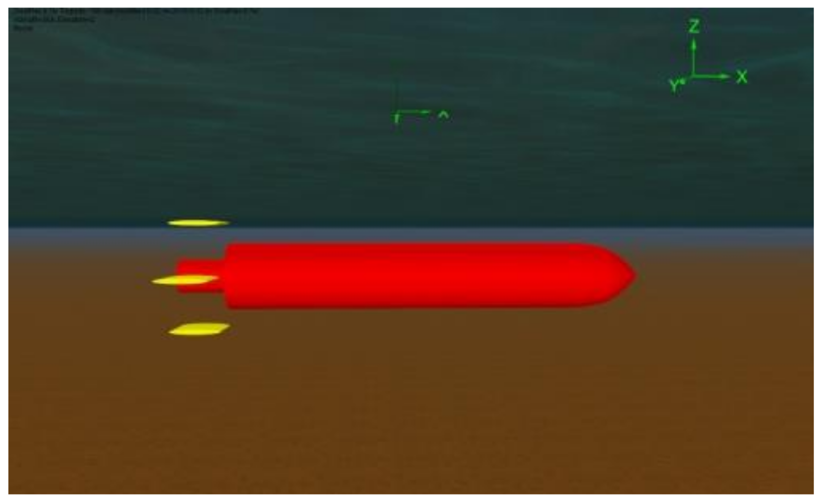
4.1. The Establishment of Simulation Model

The torpedo in this paper is modeled by the commercial software, OrcaFlex. The simulated scene is in a lentic environment, ignoring the effects of the wind, waves, and current, and the depth of water is 100 m. The torpedo model has been simulated by an OrcaFlex 6D buoy with a total length of 13.2 m. The model was divided into four sections, with the length from the head to the tail being 0.5 m, 0.7 m, 10.5 m, and 1.5 m, respectively. The outer diameters are, respectively, 1.0 m, 1.5 m, 2.0 m, and 1.0 m. An elastoplastic solid fairing with an axial and normal stiffness of 100 KN/m3 was arranged on the head of a torpedo. The overall centroid coordinates of the torpedo are (0 m, 0 m, and 0 m). In the tail of a torpedo, there are four tail wings with a wingspan of 1.5 m and a chord length of 1.5 m. The local coordinate origin of the tail fin in the torpedo body coordinate system is, respectively, (−6 m, 0 m,1.6 m), (−6 m, 1.6 m, 0 m), (−6 m, −1.6 m, 0 m), (−6 m, −1.6 m, 0 m), and (−6 m, −1.6 m, 0 m). The lift and damping coefficients of the tail wings have a low impact on the dynamic response of the torpedo. In order to save calculation time, these two coefficients are set to 0. The coordinate of the initial position of the torpedo in the global coordinate system is (0 m, 0 m, −5 m). The fixed thrust T = 50 KN in the x -direction is applied at the origin of the mine coordinate system, the normal and axial drag force coefficients of the mine body are 1.0 and 0.1, respectively, and the additional mass coefficients are both 1.0. The total simulation time is 100 s. The torpedo model is shown in Figure 1.

4.2. Results of Torpedo Direct Navigation under Munk Moment of 0

With a fixed thrust T = 50 KN, the torpedo’s Munk moment coefficients are changed to 0, 0.02, 0.04, 0.06, 0.08, and 0.10, respectively, and the torpedo-related motion parameters can be achieved by simulating the torpedo direct sailing motion and observing the change of its sailing state. Under the simulation condition that the Munk moment coefficient is 0, then the velocity diagram in the x -direction, horizontal displacement diagram in the x -direction, the depth-fixed navigation diagram and the lateral displacement diagram of the model are drawn to verify the effectiveness of the torpedo direct navigation motion model.
It can be seen from Figure 2 that during the simulation time, the speed of the torpedo reached a stable state, and the steady speed was about 20.76 m/s, which is consistent with the sailing speed of general torpedoes. The sailing distance of the torpedo reaches about 2000 m in the x-direction and basically shows a linear growth. The torpedo can maintain a stable navigation depth at this speed, which conforms to the actual working situation of the torpedo. The lateral displacement of the torpedo is basically 0 within the simulated time of 100 s. That is to say, the torpedo basically maintains straight-line navigation in the x 0 O 0 y 0 plane. The above conclusions well verify the effectiveness of the torpedo direct navigation model; therefore, the following simulation can be carried out based on this model.

5. Results and Discussion

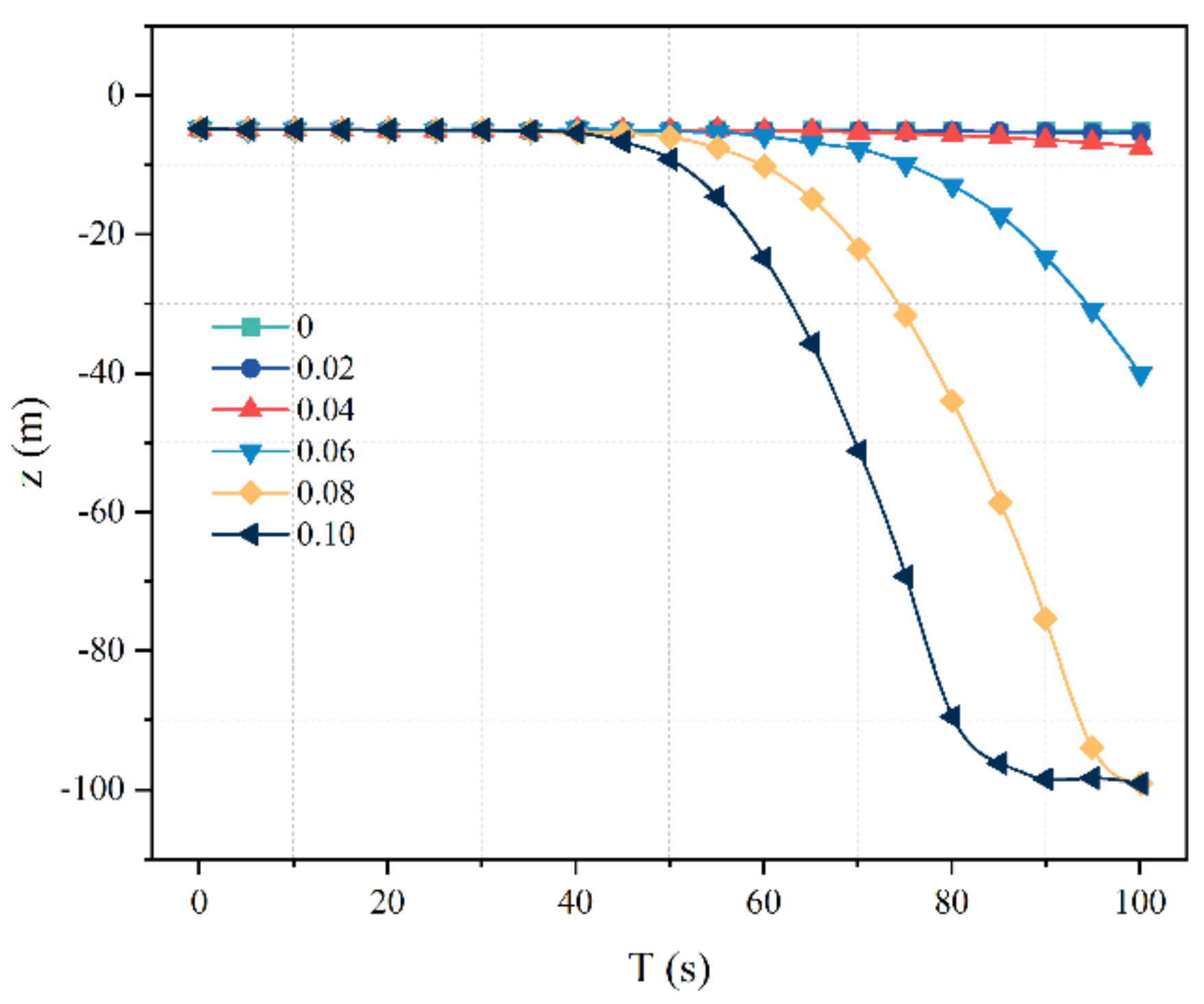
5.1. Navigation Depth and Pitch Angles under Different Munk Moment Coefficients

As can be seen from Figure 3, under the same Munk moment coefficient, the navigation depth shows an increasing trend in the time domain. At the same time, with the increase of the Munk moment coefficient, the torpedo will increase its navigation depth, and the deviation from the initial navigation depth will increase gradually. The two curves of the 0 and 0.02 Monk moment coincide. In Figure 4, the pitch angle also shows an increasing trend in the time domain. When the Munk moment coefficients are 0.06, 0.08, and 0.1, the navigation depth of the torpedo will suddenly drop from 50 s. The larger the Munk moment, the faster the torpedo will drop. The increase in pitch angle precedes the decrease in navigation depth. When the Munk moment coefficient is 0.10, the torpedo has already touched the seabed at about 81.7 s. This phenomenon can be observed in Figure 3 and Figure 4, where the curve presents obvious nonlinearity. The reasonable explanation for this phenomenon is that the pitch moment is strongly affected by the Munk moment and increases with the increase of the Munk moment coefficient. The increase in the pitch moment will lead to an increase in the pitch angle, and the thrust T acts in the negative direction of the x -axis, thus increasing the navigation depth.

5.2. Lateral Displacement and Yaw Angles under Different Munk Moment Coefficients

It can be seen from Figure 5 that in the time domain, the lateral displacement under the same Munk moment coefficient shows an increasing trend. The two curves of the 0 and 0.02 Monk moment coincide. At the same time, with the increase of the Munk moment coefficient, the lateral displacement of the torpedo will increase, and the distance from the initial motion direction will gradually increase. It can be seen from Figure 6 that in the time domain, the yaw angle under the same Munk moment coefficient also shows an upward trend. At the same time, with the increase of the Munk moment coefficient, the yaw angle of the torpedo will increase. In other words, the deviation angle from the initial movement direction will gradually increase. When the Munk moment coefficient is 0.10, the torpedo produces an abnormal yaw angle at about 81 s because the torpedo contacts the seabed. The reason for the above phenomenon is that the yaw moment is strongly affected by the Munk moment coefficient and increases with the increase of the Munk moment coefficient. It makes the torpedo yaw. More importantly, due to the yaw moment of the torpedo, the yaw angle of the torpedo increases and the lateral displacement increases.

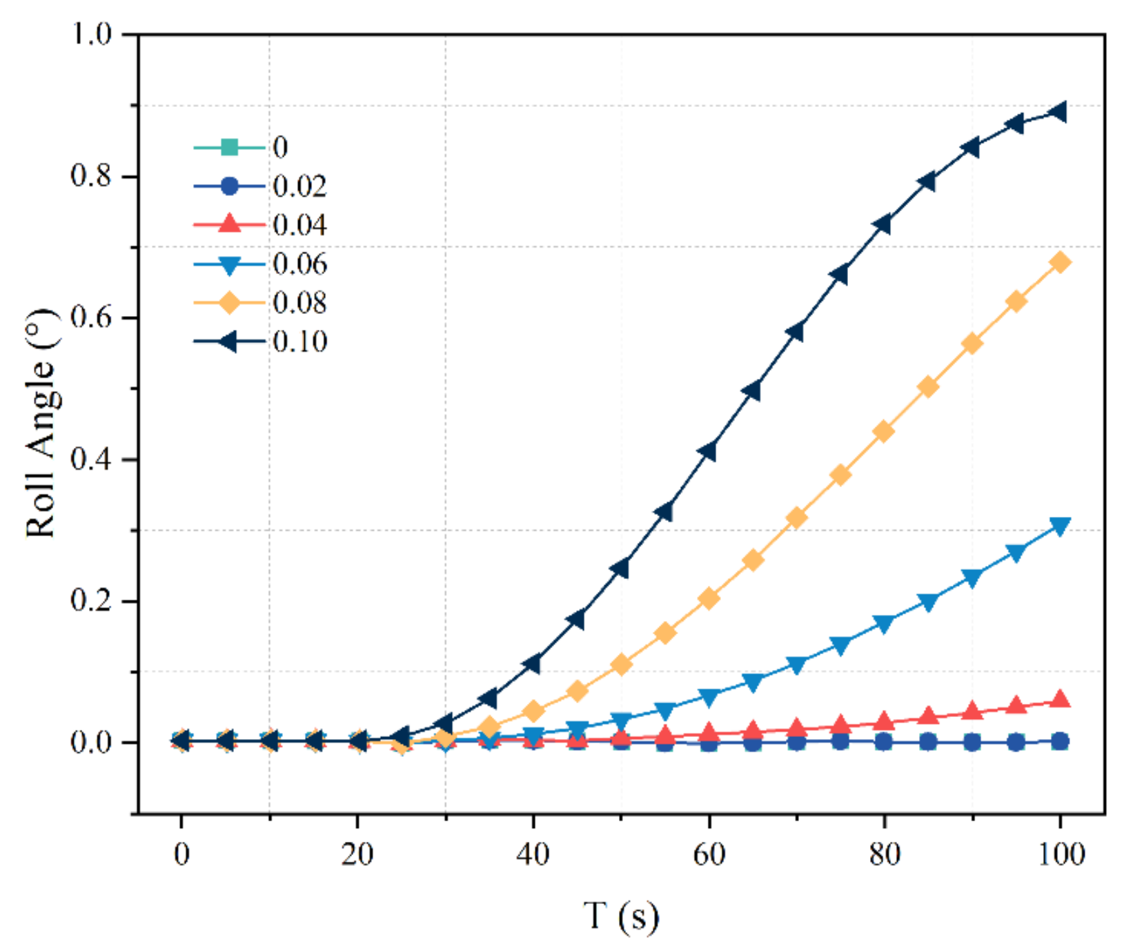
5.3. Roll Angles under Different Munk Moment Coefficients

It can be seen from Figure 7 that the roll angle presents an increasing trend under the same Munk moment coefficients in the time domain. The two curves of the 0 and 0.02 Monk moment coincide. At the same time, with the increase of the Munk moment coefficient, the amplitude of the roll angle of the torpedo will increase, and the amplitude of the rotation angle of the mine body around the x-axis will gradually increase. This is because the rolling moment is affected by the Munk moment coefficient and increases with the increase of Munk moment coefficients. The roll moment is the cause of the roll angle of the torpedo, and thus, the roll angle increases.

6. Conclusions

(1)
Based on the above derivation of the Munk moment formulas in classical torpedo navigation mechanics and the comparison of Munk moment expression in the software, OrcaFlex, it can be seen that the Munk moment coefficient mentioned in this paper is the product of the additional mass matrix and the mass of the displacement of the torpedo. Thus, the Munk moment coefficient is related to the additional mass matrix of the torpedo.
(2)
Under the same Munk moment coefficient, the navigation depth shows an increasing trend in the time domain. At the same time, the navigation depth of the torpedo will increase with the increase of the Munk moment coefficient, and the deviation from the initial navigation depth will gradually increase. Under the same Munk moment coefficient, the pitch angle also increases in the time domain. This is because the pitch moment is affected by the Munk moment coefficient and increases with the increase of the Munk moment coefficient.
(3)
Under the same Munk moment coefficient, the lateral displacement increases in the time domain. At the same time point, with the increase of the Munk moment coefficient, the lateral displacement of the torpedo will increase numerically, and the distance from the initial motion direction will increase gradually. Under the same Munk moment coefficient, the yaw angle increases in the time domain. This is because the yaw moment is affected by the Munk moment coefficient and increases with the increase of the Munk moment coefficient.
(4)
Under the same Munk moment coefficient, the roll angle increases in the time domain. At the same time, the amplitude of the roll angle of the torpedo will increase with the increase of the Munk moment coefficient, and the amplitude of the rotation angle of the mine body around the x-axis gradually increases. This is because the rolling moment is affected by the Munk moment coefficient and increases with the increase of the Munk moment coefficient.
(5)
According to classical torpedo navigation mechanics, the Munk moment is composed of pitch, roll, and yaw moments. With the expression of the Munk moment in OrcaFlex, it can only be concluded that the combined moment increases with the increase of the Munk moment coefficient, yet, the increase or decrease of each partial moment cannot be determined. However, according to conclusions (2), (3), and (4), the three moments can all increase with the increase of the Munk moment coefficient.
(6)
In conclusion, the increase of the Munk moment coefficient will lead to an increase in deflection of the torpedo’s direct sailing motion at each degree of freedom, which has an adverse effect on the torpedo’s accurate strike. According to conclusion (1), the Munk moment coefficient is related to the additional mass matrix. Therefore, in the design of the torpedo, we should reduce the additional mass of the torpedo by changing the shape of the torpedo so as to reduce the Munk moment coefficient of the torpedo and reduce the pitch, yaw, and roll moments of the torpedo.

Author Contributions

Conceptualization, D.Z. and B.Z.; methodology, D.Z. and H.J.; software, K.Z.; validation, D.Z. and K.Z.; formal analysis, D.Z. and B.Z.; investigation, K.Z. and B.Z.; resources, D.Z.; data curation, K.Z.; writing—original draft preparation, D.Z.; writing—review and editing, D.Z.; visualization, K.Z. and J.S.; supervision, D.Z. and J.S.; funding acquisition, D.Z. and H.J. All authors have read and agreed to the published version of the manuscript.

Funding

This research was funded by the Program for Scientific Research Start-up Funds of Guangdong Ocean University, grant number 060302072101, the Zhanjiang Marine Youth Talent Project—Comparative Study and Optimization of Horizontal Lifting of Subsea Pipeline, grant number 2021E5011, and the National Natural Science Foundation of China, grant number 62272109.

Institutional Review Board Statement

Not applicable.

Informed Consent Statement

Not applicable.

Data Availability Statement

Not applicable.

Conflicts of Interest

The authors declare no conflict of interest.

Abbreviations

SymbolMeaning
m The torpedo mass
L The length of the torpedo
λ The additional mass
v ˙ x , v ˙ y , v ˙ z The acceleration of the torpedo along the x-, y-, z-directions in the torpedo body coordinate system
T Thrust
C x S Resistance factor with maximum cross section S as characteristic area
ρ Density of fluid
vTorpedo speed
S The maximum cross-sectional area of the torpedo
Δ G Negative buoyancy of torpedo, ΔG = GB
x c ,   y c , z c Centroid position coordinates
ω ˙ x , ω ˙ y , ω ˙ z Angular acceleration of torpedo along x-, y-, z-directions in torpedo body coordinate system
C y α , C y δ e Position derivative of torpedo lift factor with respect to the angle of attack α and position derivative with respect to horizontal rudder angle δe
C z β , C z δ r Position derivative of side force factor to sideslip angle β and position derivative to vertical rudder angle δr
C y ω ¯ z The dimensionless factor of the rotational derivative of diagonal velocity ωz of lift
C z ω ¯ y The dimensionless factor of rotation derivative of angular velocity ωy of side force;
ω ¯ Dimensionless angular velocity
m x β , m y β Position derivative of the rolling moment factor and yaw moment factor of the torpedo to sideslip angle β
m z α Position derivative of pitching moment Factor of the torpedo to attack angle α
m x δ r , m x δ d Position derivative of torpedo rolling moment factor with respect to vertical rudder angle δr and differential rudder angle δd
m y δ r Position derivative of torpedo yaw moment factor to vertical rudder angle δr
m z δ e Position derivative of torpedo pitching moment factor to horizontal rudder angle δe
m x ω ¯ x , m x ω ¯ y Rotation derivative of rolling moment factor of ωx and ωy
m y ω ¯ x , m y ω ¯ y Rotational derivative of yaw moment factor of ωx and ωy
m z ω ¯ z Rotation derivative of pitch moment factor of ωz
Δ M x p Unbalanced moment possibly generated by a single propeller and an unbalanced counter-rotating propeller
θ ˙ Pitch angular velocity
ψ ˙ Yaw rate
x ˙ 0 , y ˙ 0 , z ˙ 0 The velocity of the torpedo in the x-, y-, z-directions in the ground coordinate system

References

  1. Panda, J.P.; Mitra, A.; Warrior, H.V. A review on the hydrodynamic characteristics of autonomous underwater vehicles. Proc. Inst. Mech. Eng. Part M J. Eng. Mar. Env. 2021, 235, 15–29. [Google Scholar] [CrossRef]
  2. Fletcher, B. UUV Master Plan: A Vision for Navy UUV Development. In Proceedings of the OCEANS 2000 MTS/IEEE Conference and Exhibition. Conference Proceedings (Cat. No. 00CH37158), Providence, RI, USA, 11–14 September 2000; pp. 65–71. [Google Scholar]
  3. Liang, Q.; Luo, M.; Wang, Y.; Hao, X. Multi-attacks effectiveness evaluation of UUV based on wake guidance. Ocean Eng. 2022, 266, 112654. [Google Scholar] [CrossRef]
  4. Sahoo, A.; Dwivedy, S.K.; Robi, P.S. Advancements in the field of autonomous underwater vehicle. Ocean Eng. 2019, 181, 145–160. [Google Scholar] [CrossRef]
  5. Ahmed, F.; Xiang, X.; Jiang, C.; Xiang, G.; Yang, S. Survey on traditional and AI based estimation techniques for hydrodynamic coefficients of autonomous underwater vehicle. Ocean Eng. 2023, 268, 113300. [Google Scholar] [CrossRef]
  6. Evans, J.; Nahon, M. Dynamics modeling and performance evaluation of an autonomous underwater vehicle. Ocean Eng. 2004, 31, 1835–1858. [Google Scholar] [CrossRef] [Green Version]
  7. Sabet, M.T.; Sarhadi, P.; Zarini, M. Extended and Unscented Kalman filters for parameter estimation of an autonomous underwater vehicle. Ocean Eng. 2014, 91, 329–339. [Google Scholar] [CrossRef]
  8. Paull, L.; Saeedi, S.; Seto, M.; Li, H. AUV navigation and localization: A review. IEEE J. Ocean. Eng. 2013, 39, 131–149. [Google Scholar] [CrossRef]
  9. Wang, C.; Zhang, F.; Schaefer, D. Dynamic modeling of an autonomous underwater vehicle. J. Mar. Sci. Tech.—Jpn. 2015, 20, 199–212. [Google Scholar] [CrossRef]
  10. Szymak, P. Mathematical Model of Underwater Vehicle with Undulating Propulsion. In Proceedings of the Third International Conference on Mathematics and Computers in Sciences and in Industry (MCSI), Chania, Greece, 27–29 August 2016; pp. 269–274. [Google Scholar]
  11. Xu, F.; Zou, Z.; Yin, J.; Cao, J. Identification modeling of underwater vehicles’ nonlinear dynamics based on support vector machines. Ocean Eng. 2013, 67, 68–76. [Google Scholar] [CrossRef]
  12. Hong, S.M.; Ha, K.N.; Kim, J. Dynamics modeling and motion simulation of usv/uuv with linked underwater cable. J. Mar. Sci. Eng. 2020, 8, 318. [Google Scholar] [CrossRef]
  13. Pan, Y.; Zhang, H.; Zhou, Q. Numerical prediction of submarine hydrodynamic coefficients using CFD simulation. J. Hydrodyn. 2012, 24, 840–847. [Google Scholar] [CrossRef]
  14. Singh, Y.; Bhattacharyya, S.K.; Idichandy, V.G. CFD approach to modelling, hydrodynamic analysis and motion characteristics of a laboratory underwater glider with experimental results. J. Ocean Eng. Sci. 2017, 2, 90–119. [Google Scholar] [CrossRef]
  15. Polis, C.D. Numerical Calculation of Manoeuvring Coefficients for Modelling the Effect of Submarine Motion Near the Surface. Ph.D. Thesis, University of Tasmania, Tasmania, Australia, 2018. [Google Scholar]
  16. Liu, X.; Hu, Y.; Mao, Z.; Tian, W. Numerical Simulation of the Hydrodynamic Performance and Self-Propulsion of a UUV near the Seabed. Appl. Sci. 2022, 12, 6975. [Google Scholar] [CrossRef]
  17. Lee, S.; Lee, S.; Bae, J. Maneuvering Hydrodynamic Forces Acting on Manta-type UUV Using CFD. J. Ocean Eng. Tech. 2020, 34, 237–244. [Google Scholar] [CrossRef]
  18. Rehman, F.U.; Huang, L.; Anderlini, E.; Thomas, G. Hydrodynamic modelling for a transportation system of two unmanned underwater vehicles: Semi-empirical, numerical and experimental analyses. J. Mar. Sci. Eng. 2021, 9, 500. [Google Scholar] [CrossRef]
  19. Tyagi, A.; Sen, D. Calculation of transverse hydrodynamic coefficients using computational fluid dynamic approach. Ocean Eng. 2006, 33, 798–809. [Google Scholar] [CrossRef]
  20. Le, T.; Hong, D. Computational fluid dynamics study of the hydrodynamic characteristics of a torpedo-shaped underwater glider. Fluids 2021, 6, 252. [Google Scholar] [CrossRef]
  21. Ling, X.; Leong, Z.Q.; Chin, C.; Woodward, M.; Duffy, J. Regression analysis and curve fitting for the hydrodynamic coefficients of an underwater vehicle undergoing straight-ahead motion. Ocean Eng. 2022, 262, 112135. [Google Scholar] [CrossRef]
  22. Zhang, J.; Chang, Z.; Lu, G.; Zheng, Z.; Zhang, Z. Analysis of the Dynamic System of Wave Glider with a Torpedo. J. Ocean Univ. China 2020, 19, 519–524. [Google Scholar] [CrossRef]
  23. Kilavuz, A.; Ozgoren, M.; Kavurmacioglu, L.A.; Durhasan, T.; Sarigiguzel, F.; Sahin, B.; Akilli, H.; Sekeroglu, E.; Yaniktepe, B. Flow characteristics comparison of PIV and numerical prediction results for an unmanned underwater vehicle positioned close to the free surface. Appl. Ocean Res. 2022, 129, 103399. [Google Scholar] [CrossRef]
  24. Anderson, J.M.; Chhabra, N.K. Maneuvering and stability performance of a robotic tuna. Integr. Comp. Biol. 2002, 42, 118–126. [Google Scholar] [CrossRef] [PubMed] [Green Version]
  25. Hakamifard, M.; Rostami VF, M. Numerical and Analytical Calculation of Munk Moment in Real Flow for an Autonomous Submarine in Pure Sway Motion in PMM Test. J. Solid Fluid Mech. 2019, 9, 205–216. [Google Scholar]
  26. Hasanloo, D.; Pang, H.; Yu, G. On the estimation of the falling velocity and drag coefficient of torpedo anchor during acceleration. Ocean Eng. 2012, 42, 135–146. [Google Scholar] [CrossRef]
  27. Zhan, J.; Lu, X.; Zhang, X.; Li, G. Numerical calculation and analysis of trimaran’s additional mass. J. Huazhong Univ. Sci. Tech. (Nat. Sci. Edit.) 2013, 41, 109–113. (In Chinese) [Google Scholar]
Figure 1. Schematic diagram of torpedo model.
Applsci 13 04169 g001
Figure 2. Validation results: (a) torpedo’s speed in the x-direction; (b) horizontal displacement in the   x -direction; (c) torpedo’s navigation depth; (d) torpedo’s lateral displacement.
Applsci 13 04169 g002
Figure 3. Navigation depth under different Munk moment coefficients.
Applsci 13 04169 g003
Figure 4. Pitch angle under different Munk moment coefficients.
Applsci 13 04169 g004
Figure 5. Lateral displacement under different Munk moment coefficients.
Applsci 13 04169 g005
Figure 6. Yaw angles under different Munk moment coefficients.
Applsci 13 04169 g006
Figure 7. Roll angles under different Munk moment coefficients.
Applsci 13 04169 g007
Disclaimer/Publisher’s Note: The statements, opinions and data contained in all publications are solely those of the individual author(s) and contributor(s) and not of MDPI and/or the editor(s). MDPI and/or the editor(s) disclaim responsibility for any injury to people or property resulting from any ideas, methods, instructions or products referred to in the content.

