1. Introduction
This article presents an alternative project proposal using new construction technologies that adapt construction procedures and support from an original project. The overall objective is to justify the new excavation and support systems and to evaluate the safety levels with which the Desierto de los Leones tunnels in the Poetas Highway, Mexico, were built.
The internal section of the tunnels defined in the project was fully respected, while the excavation section was adapted to fit the proposed treatments; the secondary support system is installed to ensure the long-term stability of tunnels [
1,
2,
3].
The design of tunnels can be approached using various different methods, such as analytical solutions, numerical simulations or the convergence-confinement method (CCM) [
2,
3,
4,
5,
6,
7,
8,
9]. Numerical simulations have been widely employed in the analysis of underground projects to consider more complex geological conditions.
As part of this article has been included a summary of the lithological characteristics of the different units described in the project, a reinterpretation of the geotechnical properties, a description of the new construction procedures to be implemented and a series of calculations using finite data differences method, as well as a discussion of the results is presented. Additionally, this article also reports on how the tunnels have worked since construction was completed.
Models and calculations are based on the geological and geotechnical information included in the original project.
2. Excavation and Sustainability Analysis
2.1. Brief Description of the Geotechnical Conditions
The most relevant information was extracted from the original project, where it was used to characterize the land in terms of its physical and geotechnical properties. The objective was to prepare a sufficiently realistic geomechanical model to calculate the behaviour of the excavations and the supports proposed in this project. Below is a brief description of the most important characteristics of the different geological units.
Based on the geology of the Valley of Mexico described by [
10,
11], we have classified the different geology series through which the tunnel digs:
2.1.1. Series of Fine Tuffs or Redeposited Tuffs
This silty-clayey tuff soil shows a high alteration of the vitreous materials that made up the original tuff. The sandy and gravel fraction provides its frictional properties. Some pumice horizons are also observed. The cohesion values obtained in the different tests carried out on this material range between 0.3 and 3.2 kg/cm2 and the angle of internal friction ranges from 18 to 36 degrees. The reported deformability modules are between 40 and 57 MPa.
2.1.2. Lower Pumitic Tuff
These pumitic tuffs are the product of the deposition of pyroclastic materials with very thin and thin pseudostrata 5 mm wide by 1 or 2 cm long (Ignimbrites structure). Their grain size ranges from coarse sand to gravel and they are very to moderately altered. Their moisture content is between 80 and 100%. Cohesive strength ranged from 0.1 to 1.2 kg/cm2, the angle of internal friction ranges from 18 to 35 degrees and the modulus of elasticity from 39 to 57 MPa.
2.1.3. Lower Tuff
This series of silty-sandy to sandy-silty tuffs are the product of the alteration of andesites and dacites. They have a scarce sandy or gravel fraction. During laboratory study, the cohesion values are determined to be between 0.3 and 2.3 kg/cm2, the angle of internal friction ranges from 23 to 37 degrees and the modulus of elasticity is between 59 and 122 MPa. In the PCA of the exploration campaign, the layers were very wet and the laboratory moisture contents was between 40 and 60%.
2.1.4. Lahar
This series of pyroclastic deposit of heterogeneous aggregates, has greater resistance properties than the other units, due to the nature of their deposition. It has a glassy-crystalline matrix with a sandy appearance whose particles are welded. It is andesitic in composition and includes boulders up to 50 cm thick. In the laboratory, it showed a cohesion of 0.6 to 1.6 kg/cm2 and an angle of internal friction of 21 to 40 degrees, with a Young’s modulus of approximately 70 MPa. Very few tests were performed on this unit.
2.1.5. Uncontrolled Fillings
In the area of the south portal, there is a unit of anthropic fillings of a not very well-defined thickness and that are the product of construction activities from the time when houses were built in the area. It is possible that, in the first few meters of the tunnel, a good part of the excavation section will be within this unit. There is no adequate geotechnical characterization of this unit, or laboratory tests. It is estimated that it will be the material with the worst geotechnical characteristics.
3. General Characteristics of the Terrain and Excavations
The four units characterized in the study can be considered to be in the range of hard soils, although its resistance and deformability properties depend significantly on factors that are not easy to control, such as the natural heterogeneities presented in these types of formations and the presence of water. The composition and mechanical properties of the uncontrolled fillings are unknown.
Tunnels can be dug with a good safety margin if rapid stabilization techniques are adopted with short feeds. The poorer quality sections, and especially the shallow ones, require more sophisticated stabilization techniques, such as micropile (umbrella) lines. The shallow depth and the greater degree of alteration in the areas near the portals can trigger instability phenomena from the front if support measures are not adopted. A very important factor to consider is the possible presence of strata or lenses of sandy material that could be saturated and loose, especially in the upper parts of the excavation. Leading systems to provide security are essential in these.
Although they are usually stable, he soils that the tunnels will affect do not have a very high stiffness. Due to the dimensions of the excavations, a very rigorous control of the deformational behavior will be required. This can be achieved by placing measurement stations as close as possible to the front.
The technique by which the tunnels will be built, unlike other more traditional ones using multiple sections, consists of excavating large sections (full upper half section), in short advances and placing the support immediately after the advance. In addition, the structural elements (metal frames) will be completely covered with shotcrete, that will provide a rigid reinforcement close to the front. This methodology has proven to be safer than traditional methods, especially due to the rigidity of the support. In addition, it generates deformations of a smaller magnitude. On the other hand, to work under this concept requires highly efficient machinery and equipment and the construction cycles that this method entails guarantee continuous progress and better work execution times.
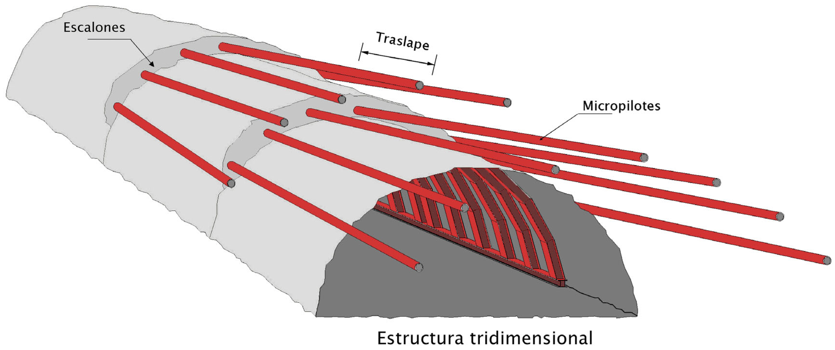
The front row concept starts from the need to stabilize the vault before it is excavated and is generally used in particularly bad terrain. It is a set of sub-horizontal linear structural elements drilled in the ground, directed towards the advance of the excavation and, generally, injected. These constitute a pre-vault formed by resistant material, the purpose of which is to avoid the tendency of the ground to break in the area of influence of the excavation front.
Frontal looping systems are more than 50 years old. In the last decade, they have evolved in a very important way, both in the theoretical understanding of the concept and in the manufacturing and commissioning technologies.
When the structural elements are made of steel, as can be seen in
Figure 1, they are usually classified as light and heavy; the light elements are generally formed by bars or conventional steel rods and the heavy elements by tubes. There are alternatives, such as the reinforced vaults using Jet Grouting umbrellas or another type of injection for the improvement of the terrain.
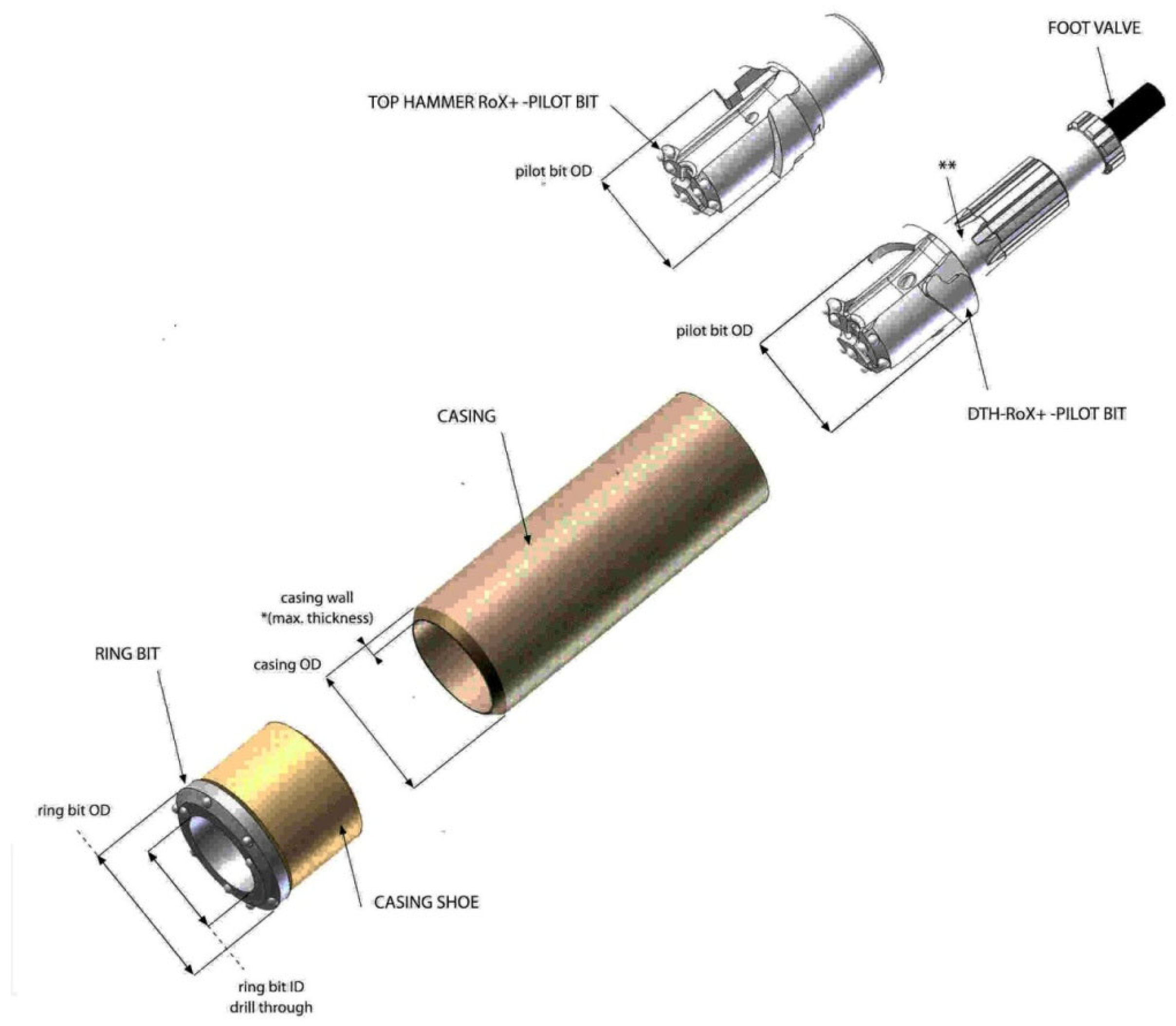
Currently a system that is providing very attractive productivity results is that of self-drilling micropiles (
Figure 2). The system consists of a series of pieces that are attached to the front of the tube and a boring bar that passes through it, attached to the rotating mechanism of the jumbo. The crown mouth is almost the same diameter as the pipe and is a non-recoverable part, while the pilot mouth is removed at the end of the hole, along with the boring bar.
This system implies that the drilling diameter is equal to (or almost equal to) that of the pipe, so it is not necessary to fill the space between the tube and the hole. However, the tube can be slotted so that the pressurized injection penetrates the ground, forming a strong ring.
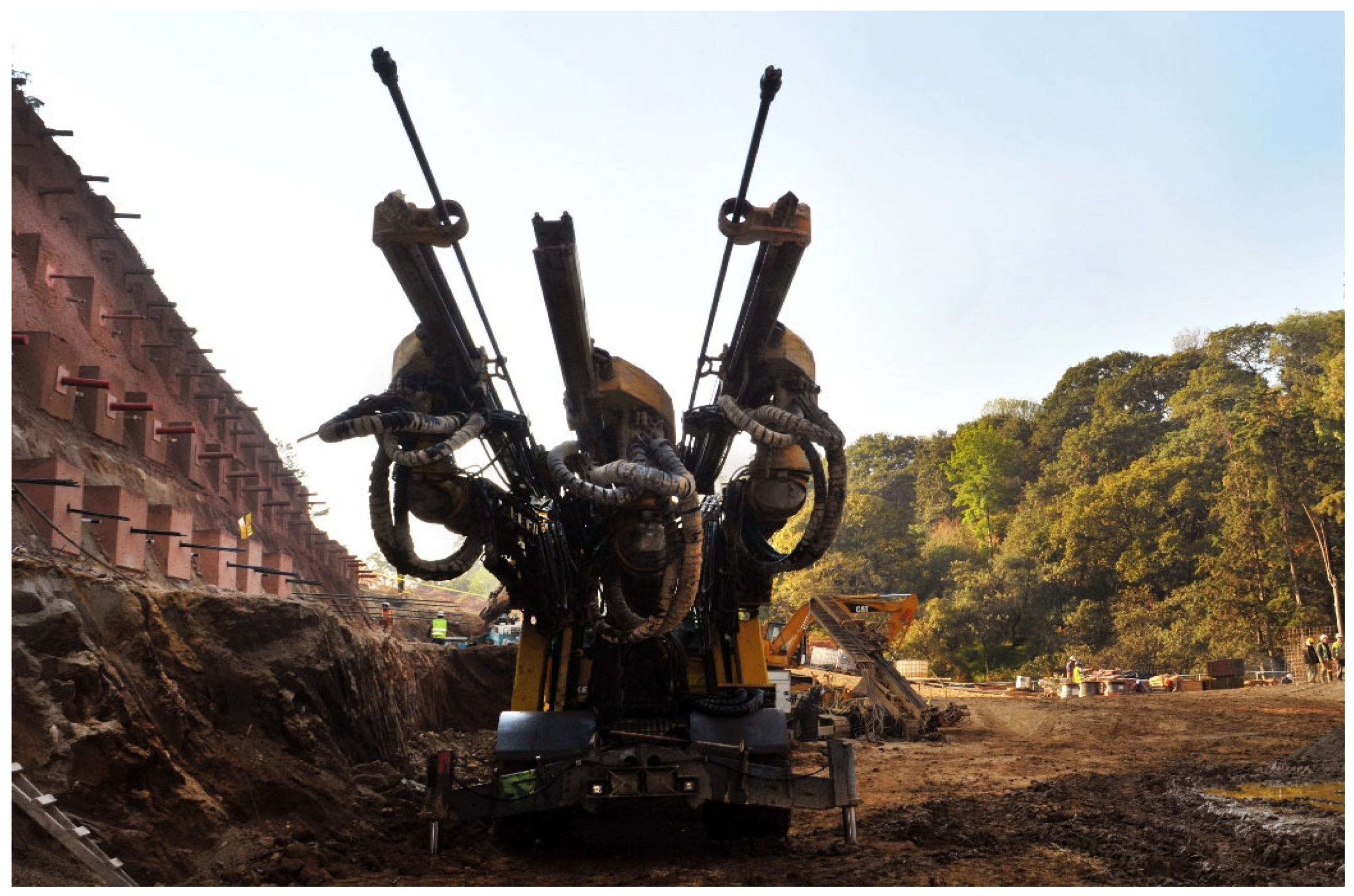
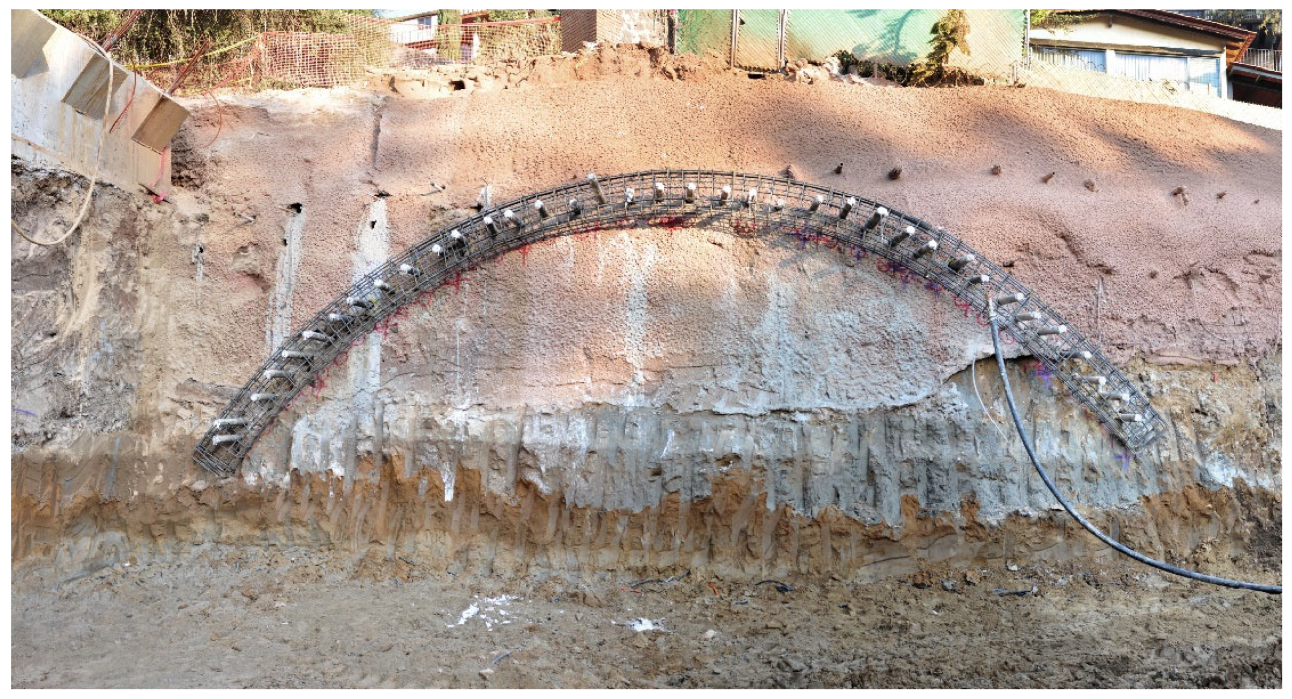
The system is fully adaptable to the drilling jumbo and construction practice (
Figure 3 and
Figure 4) has shown that, inside the tunnel, this equipment is more versatile than others. In addition to having much greater mobility, they adapt better to production cycles.
3.1. Analysis of Excavation and Support Systems
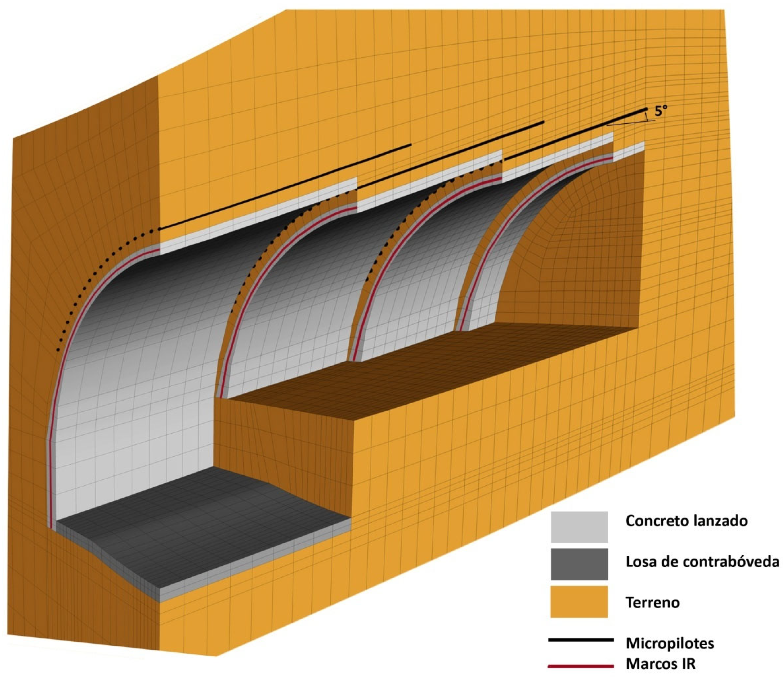
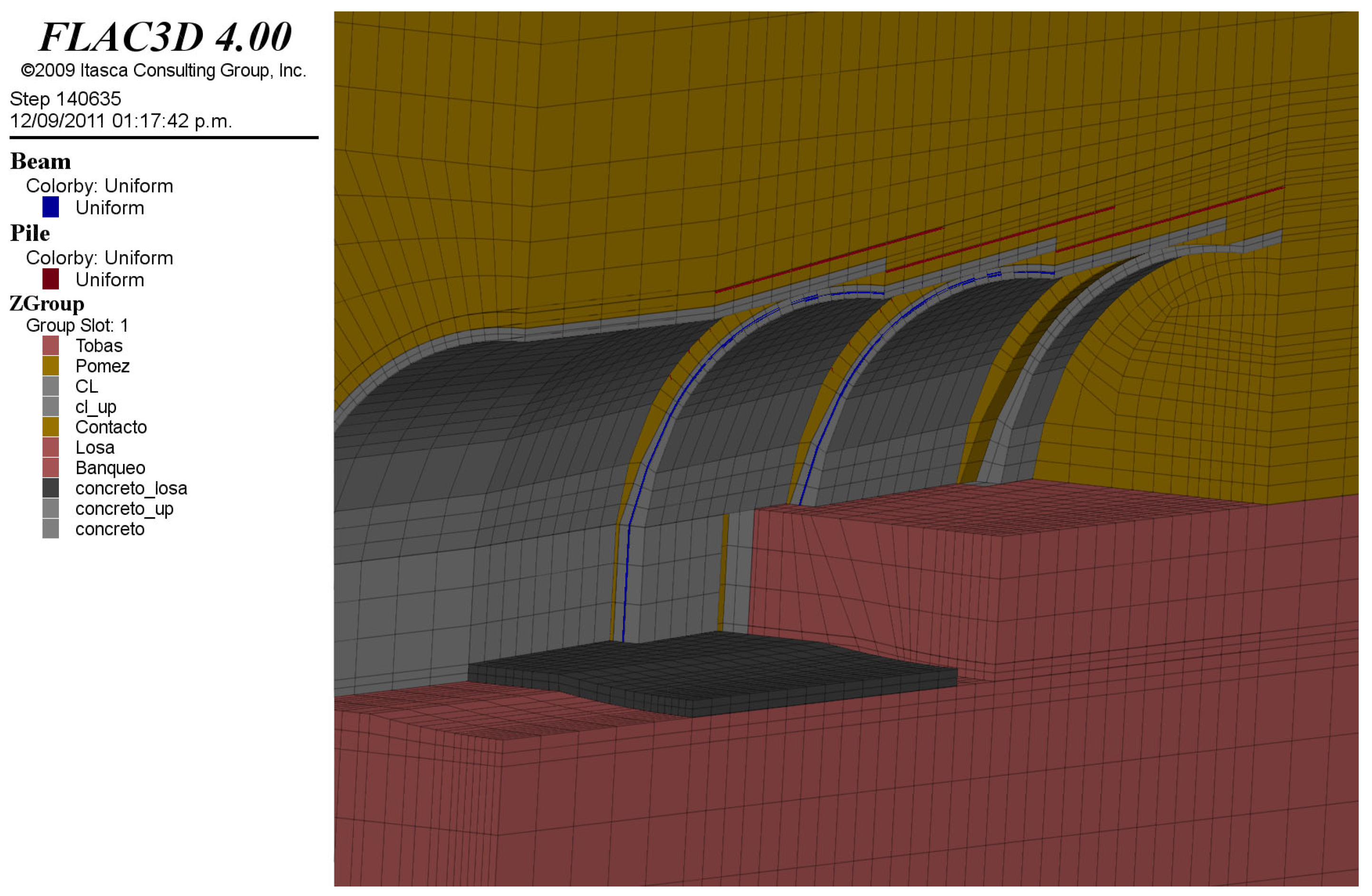
Figure 5 and corresponding to the schemes of the adaptation to the tunnel project, seven types of support have been specified to adapt to the entire range of possible geotechnical conditions that might arise during excavations.
To study the behavior of the work and the performance of the different structural elements that will make up the support, a calculation model based on the finite difference technique has been used. The calculations reproduce both the excavation procedure, with the exact geometry of the advance sections, the length of the pass and the placement times of the structural elements. A diagram of the analysis mesh is shown in
Figure 5.
3.1.1. Calculation Parameters
The mechanical parameters for the stress-strain calculations were estimated from the studies produced for the original project. The project report contains a vast collection of results from laboratory tests and on-site trials. There is a great dispersion in the results of the tests. Nevertheless, the original design presents a classification by ranges of values of the parameters of the main units. The only unit for which there are no trials is the so-called uncontrolled fillings. Notwithstanding this, when these modelling and calculation works began, the excavations of the open pit of the South Portal had already begun and the land formed by the said fillings could be visually characterized. We used the parameters proposed by the designer for the stability analysis of the slopes of the South Portal, since they fall within the so-called uncontrolled landfill zone.
According to the geotechnical profile presented by the original designer, the tunnel will mostly extend through the pumitic series and the lower tuff unit, although, towards the North Portal area, the lower part of the excavation section possibly includes the lahars.
The pumitic unit and the lower tuff are geotechnically similar, according to the project report itself. Their parameters are orders of magnitude similar, and the boundary between these two units appears to be a bit fuzzy.
Table 1 shows the parameters used in the calculations by the designer’s company.
As previously stated, to define the parameters of the new calculations it was necessary to start from those established by the original designer in the laboratory and with on-site testing. However, after a review of the results of those campaigns, and based on our own experience, the parameters shown in
Table 2 were proposed.
3.1.2. Cases Studied
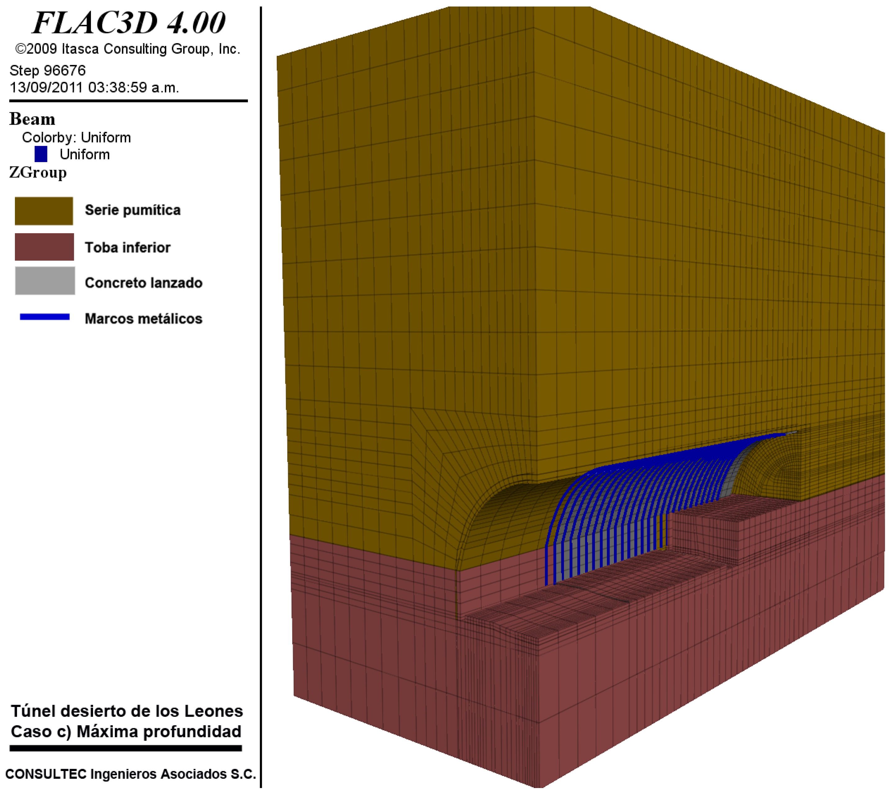
To justify the change in excavation and support procedures, three series of three-dimensional analyzes were made: (a) Excavation with little coverage in the area of uncontrolled fillings; (b) excavation with little coverage in the area near the South Portal within the units of the pumitic and lower tuff series; (c) excavation in the zone of maximum depth, also within the lower tuff units and pumitic series.
3.1.3. Sustains Studied
For cases a and b, the construction procedures for the ST-E, ST-5A and ST-5B type sections of the new proposal were considered. The placement of the micropiles umbrellas, the shotcrete, the IR metal frames and the reinforced concrete slab in the counter vault were considered. For case (c), the ST-4 type support was considered.
For the structural revision of shotcrete, the resistance is made to vary over time according to the recommendations of the ICE manual [
14] for supports
Table 3, and with the laboratory data provided by the contractor. In
Table 1 adopted resistance values are displayed.
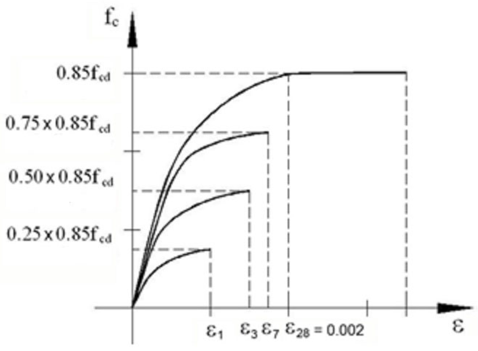
In accordance with these recommendations, and based on a typical rectangular-parabolic stress-strain law of concrete [
15], the hypothesis of evolution of the stress-strain relationship of shotcrete was established.
In
Figure 6, f
cd shows the design resistance of the concrete, which is equal to the value of the characteristic design resistance
, divided by a partial safety factor (
η = 0.85).
The modulus of elasticity of shotcrete is calculated as:
where E
28 is the modulus of elasticity of shotcrete and
is the characteristic strength of concrete at 28 days.
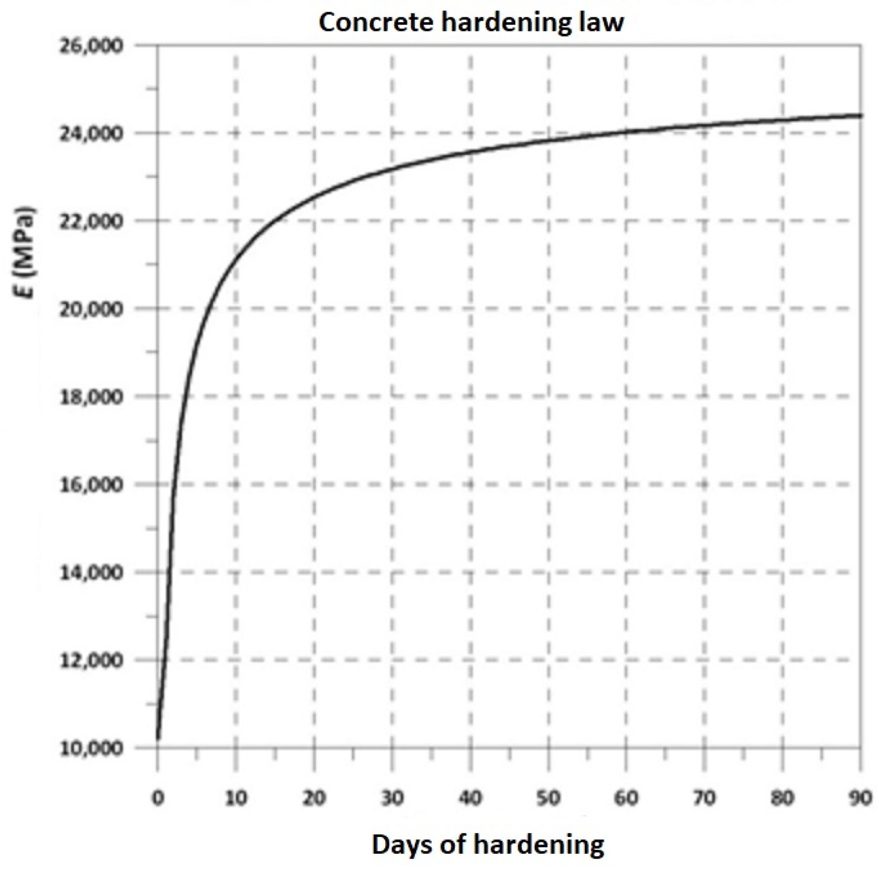
To calculate the variation in the modulus of elasticity of shotcrete (with rapid hardening) the following expressions can be used [
14,
15,
16].
where the parameter
[
17] and the parameter
is for fast setting concrete.
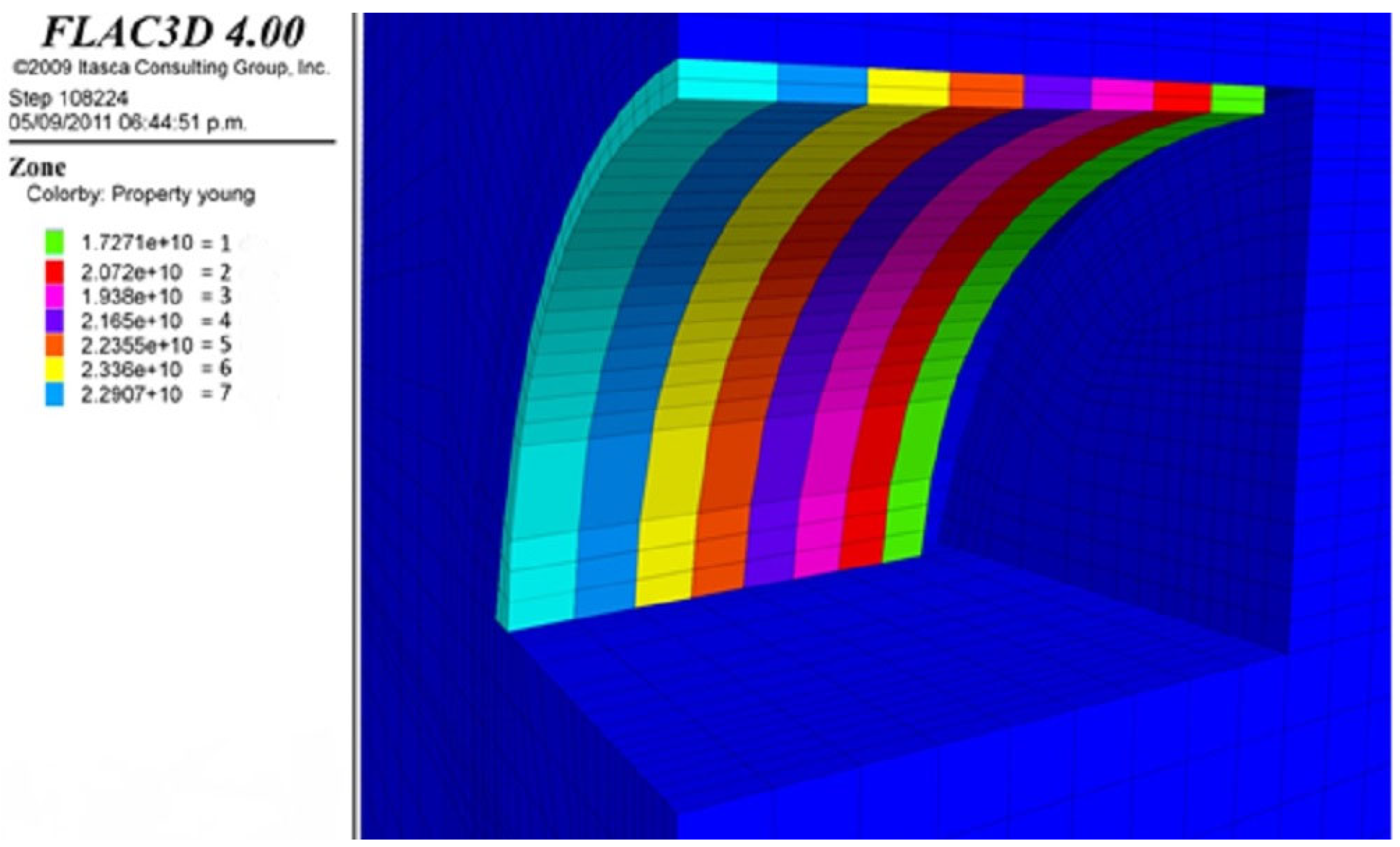
Figure 7 shows the evolution curve of the modulus of elasticity of shotcrete. This hardening law can be introduced in the numerical analysis code to be applied during the simulation of the excavations.
When the structural analysis of the support is carried out by inelastic methods (i.e, allowing the shotcrete or the frames to enter the plastic or fracture range at some points in a way that redistributes its efforts until it is no longer possible to maintain its stability), the resistance parameters required for the numerical analysis are: the plasticizing axial load Pp and the plasticizing moment Mp.
Figure 8 shows the support of colored shotcrete according to age and the corresponding modulus of elasticity.
3.1.4. Excavation in the Landfill Area
The simulation of the construction procedure is carried out as follows:
- -
Creation of the initial state of efforts, considering the Jaky criterion for the definition of the horizontal component.
- -
Placement of the first group of micropile umbrellas.
- -
Excavation of a 1.0 m advance from the upper half section.
- -
Placement of shotcrete and 8” IR steel rib. Shotcrete has a stiffness and resistance typical of an age of 1 day.
- -
Next advance of 1.0 m of the upper half section.
- -
Placement of shotcrete and 8”IR steel rib. Shotcrete has a stiffness and resistance typical of an age of 1 day and the previous section of shotcrete evolves at an age of 2 days.
- -
Successive cycles until the upper half section is completed.
- -
Bench in advances of 2 m.
- -
Placement of 1-day-old shotcrete and steel ribs legs.
- -
Casting the slab of the counter vault to the front of the bench. The reinforced concrete of the counter vault has a stiffness and resistance typical of an age of 1 day.
- -
Next bench advance.
- -
Placement of 1-day-old shotcrete and steel ribs legs.
- -
Casting the slab of the counter vault to the front of the bench. The reinforced concrete of the counter vault has a stiffness and resistance typical of an age of 1 day and that of the previous advance an age of 2 days.
- -
Successive cycles until the tunnel is completed.
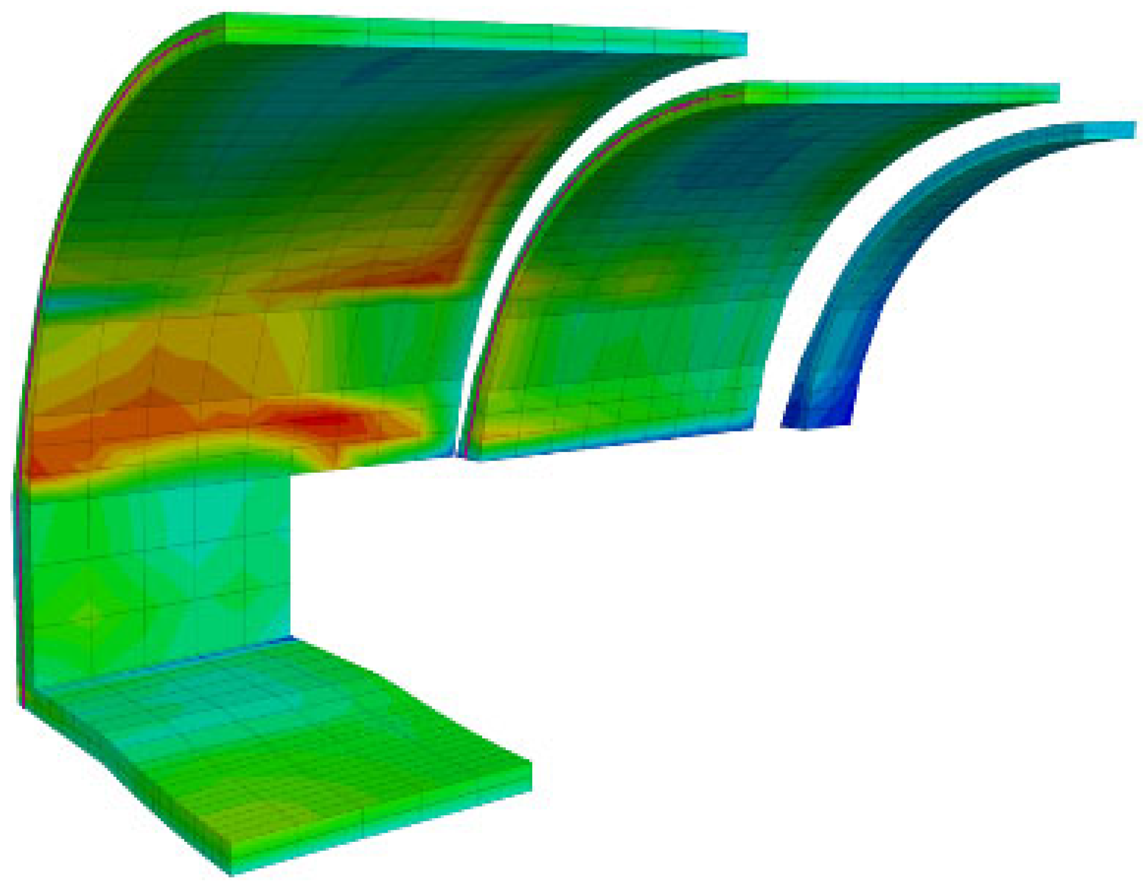
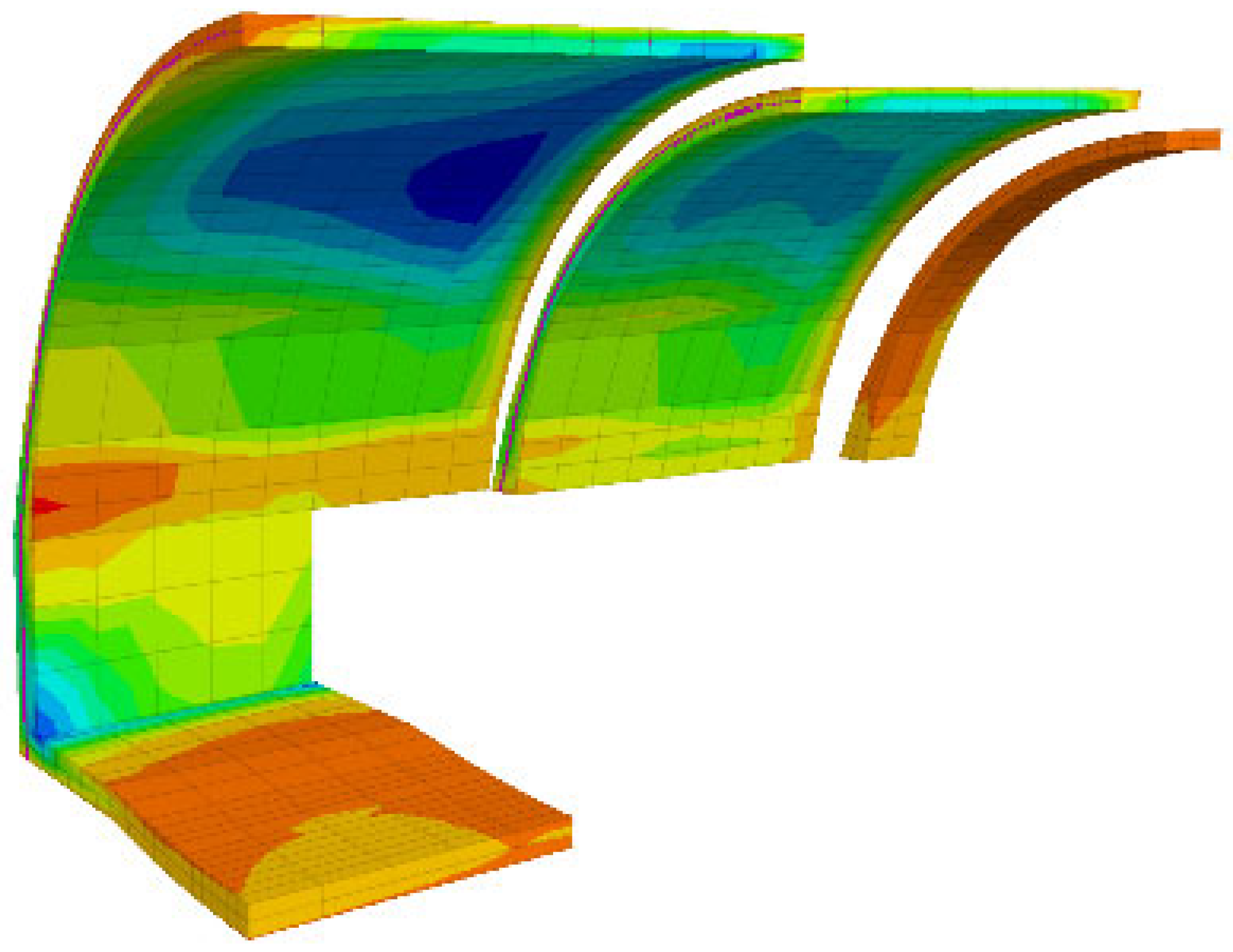
Excavation analyses were performed in a 30 m section with an average coverage of 8 m for three combinations of mechanical parameters (low, medium and high parameters), within the range defined for the fill zone (
Table 2).
Figure 9,
Figure 10,
Figure 11,
Figure 12,
Figure 13 and
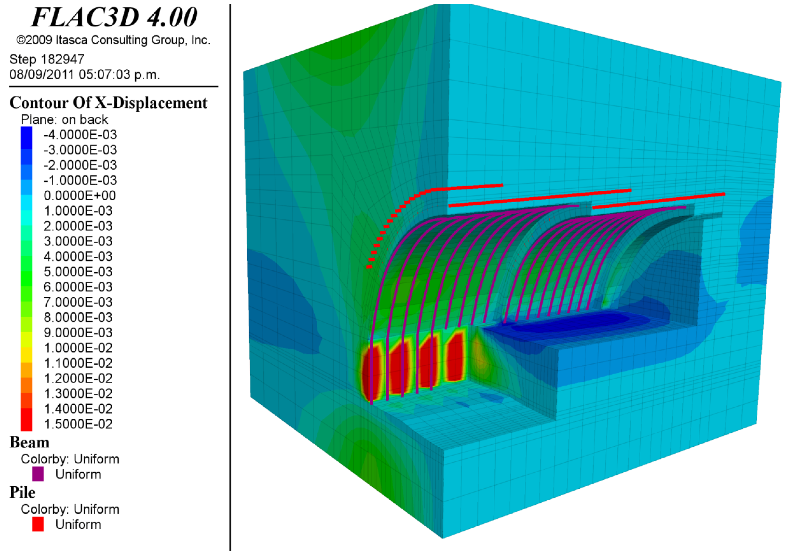
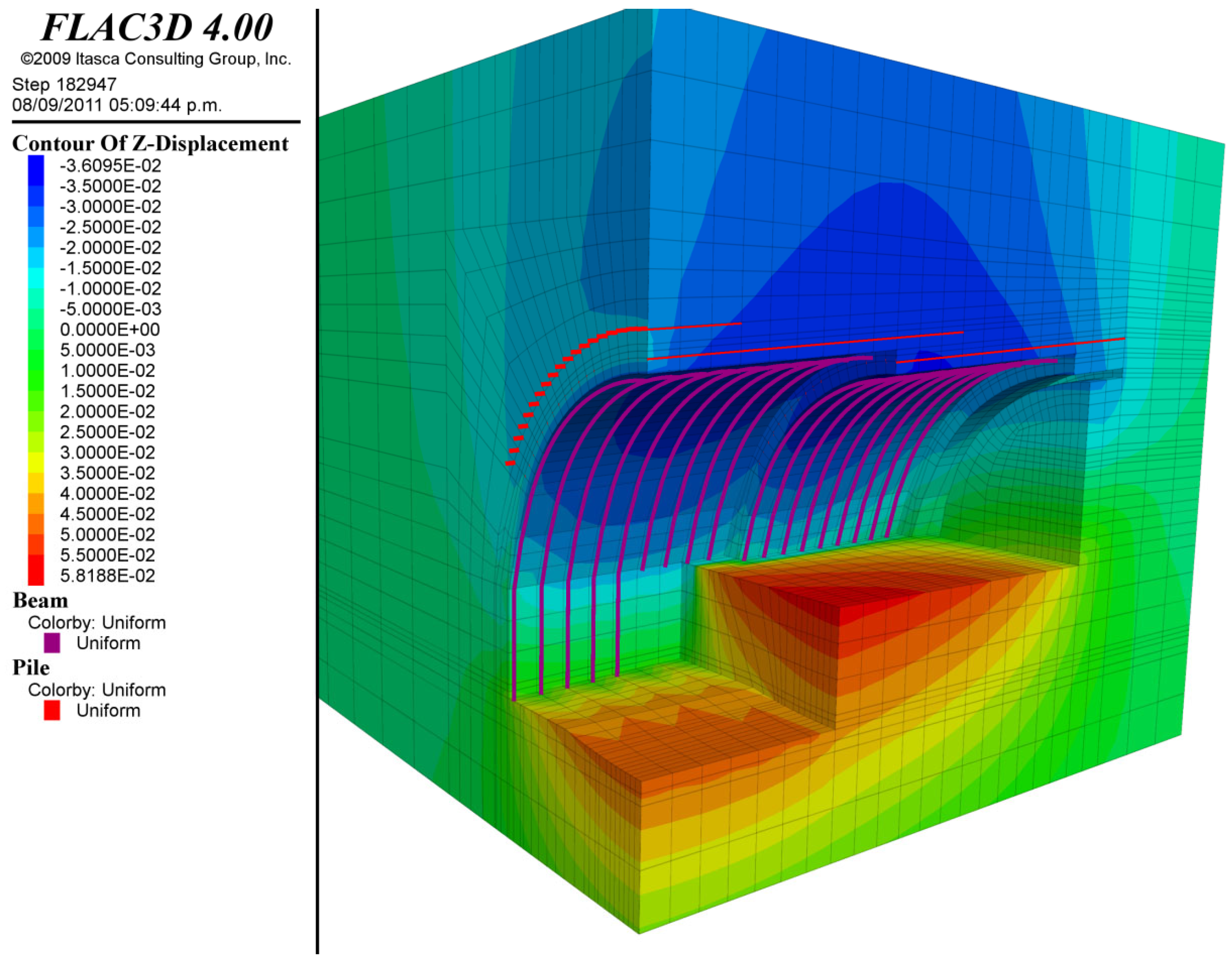
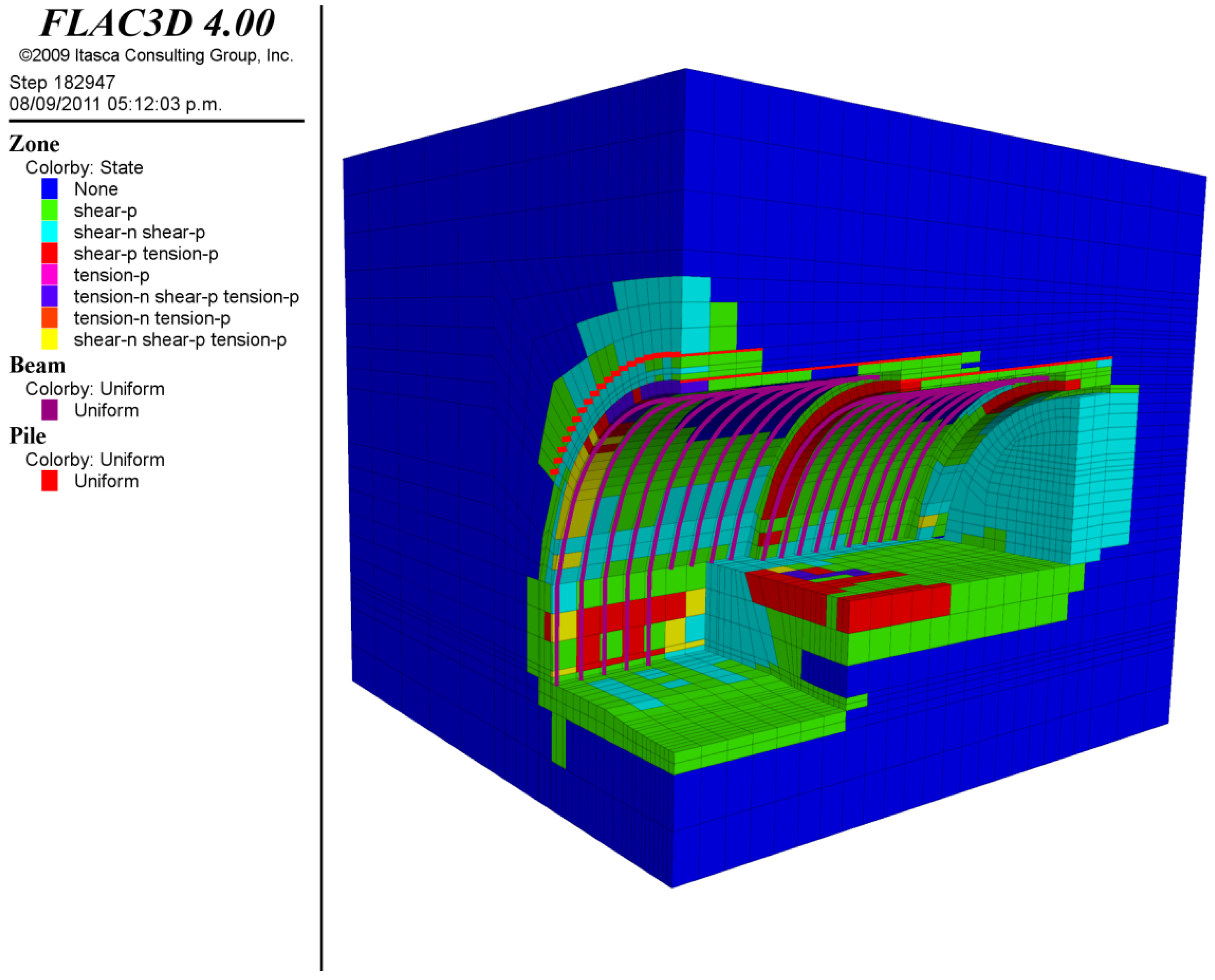
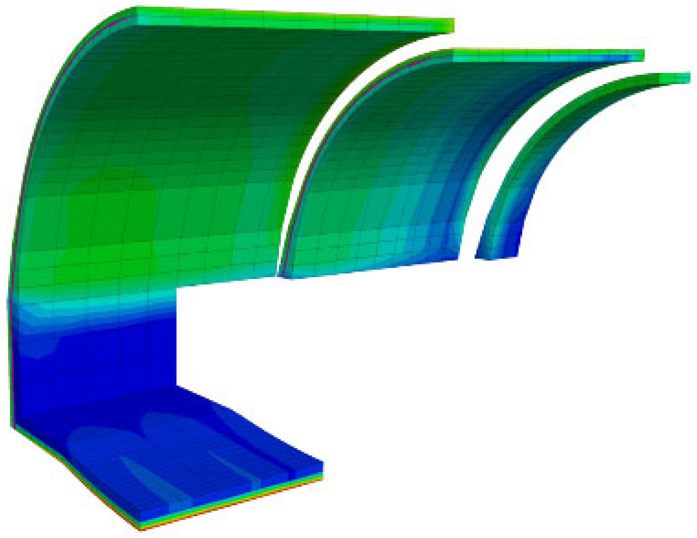
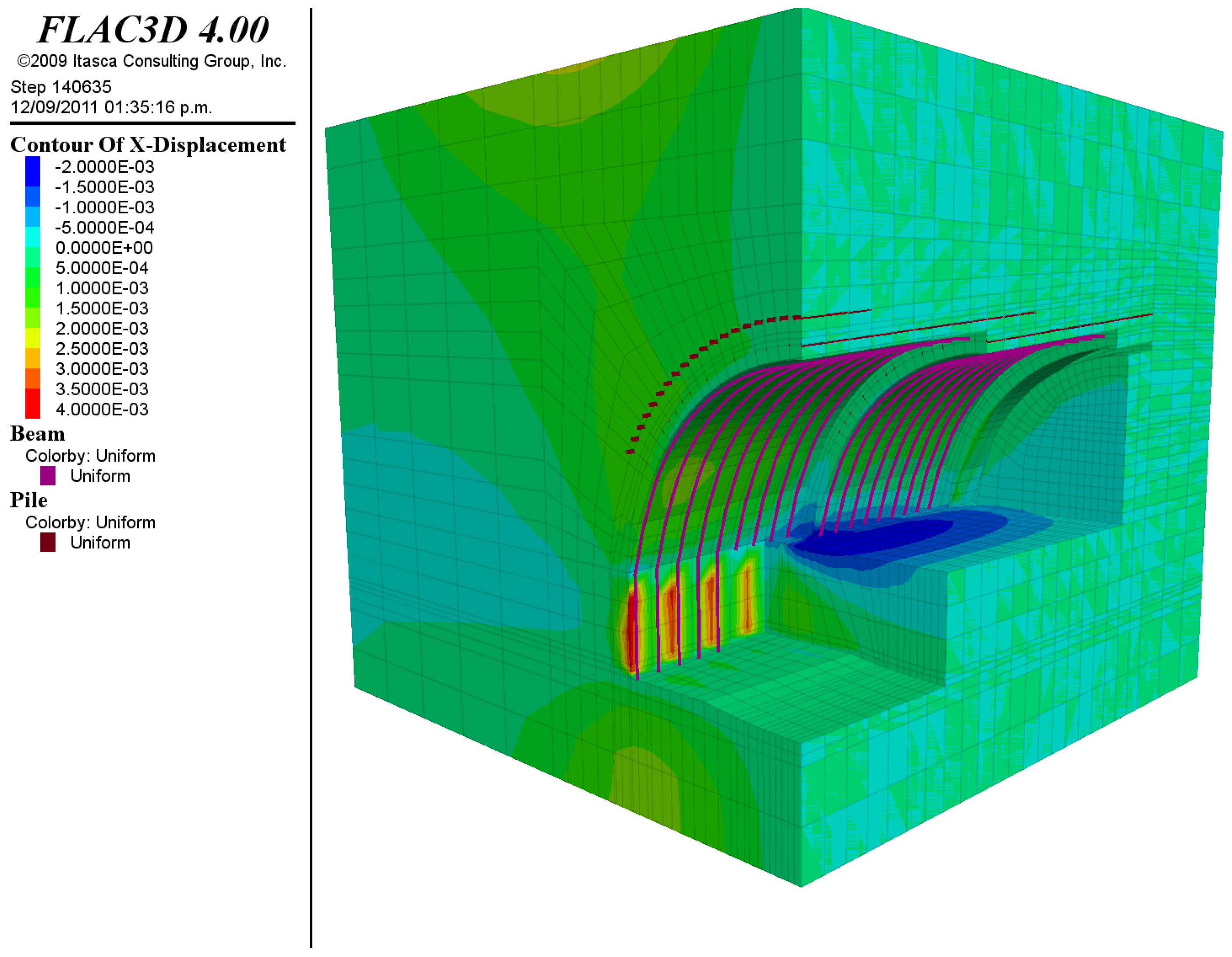
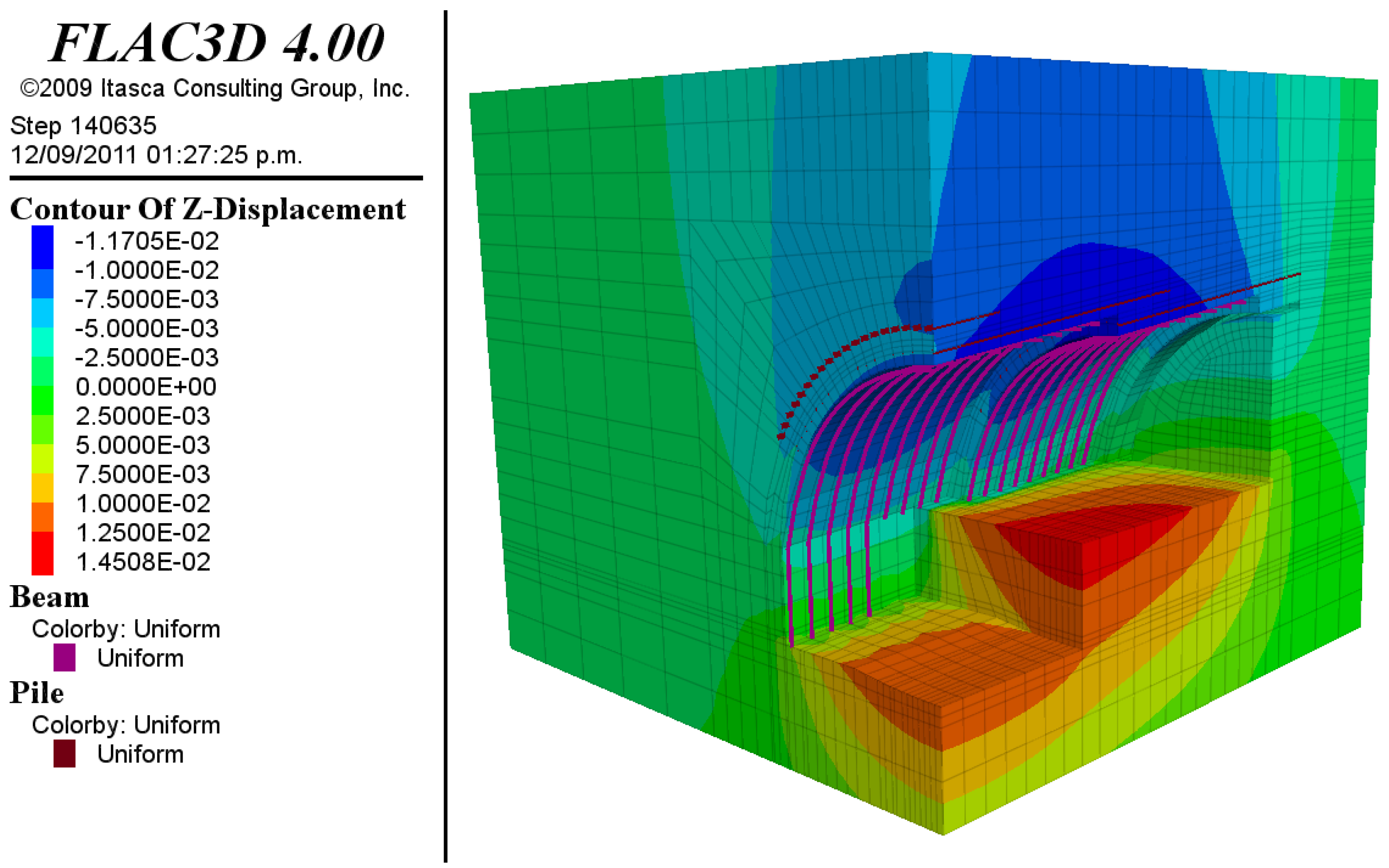
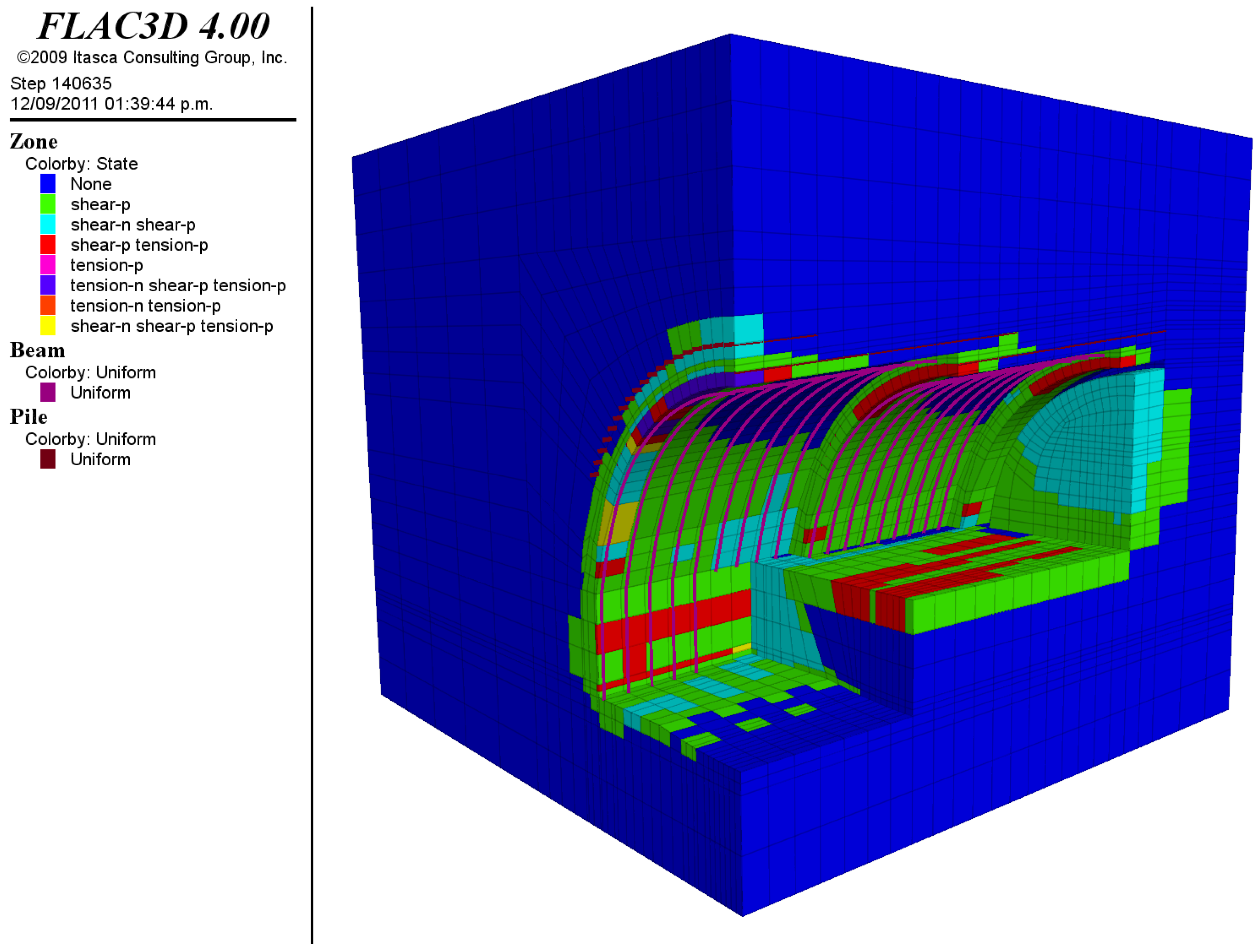
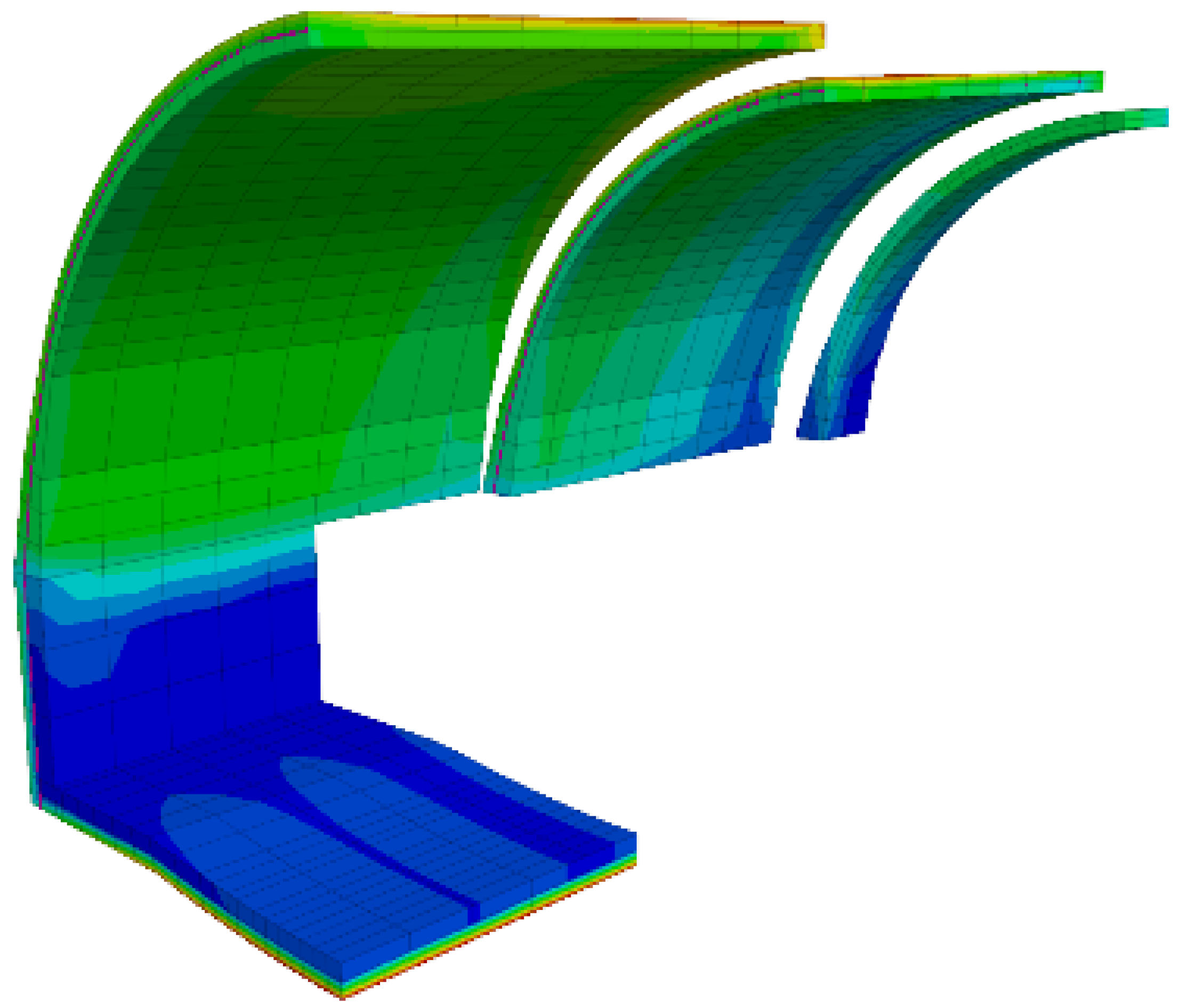
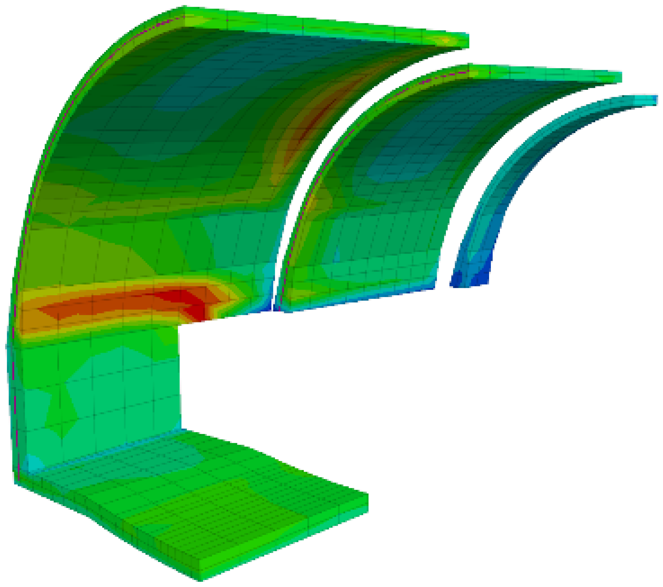
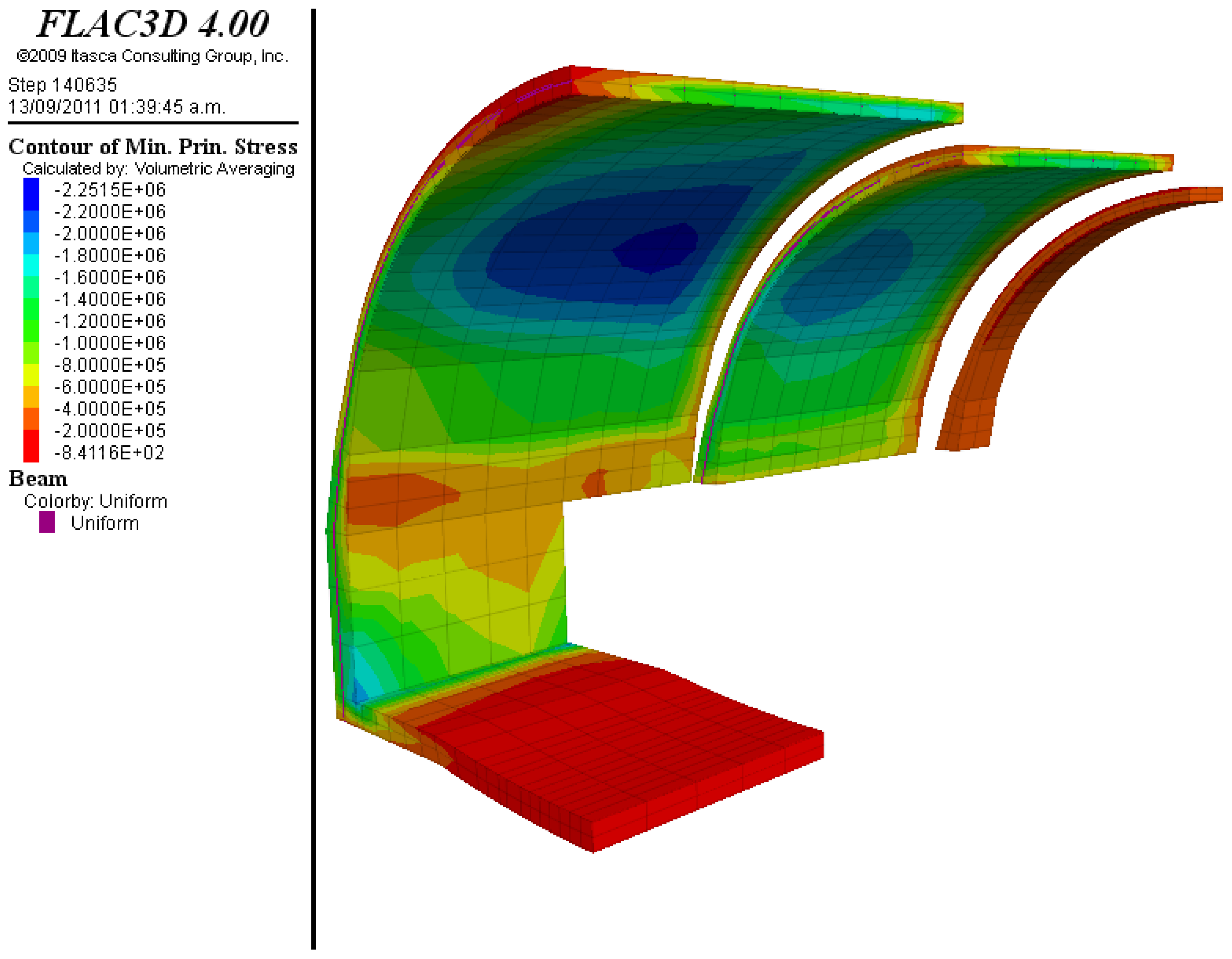
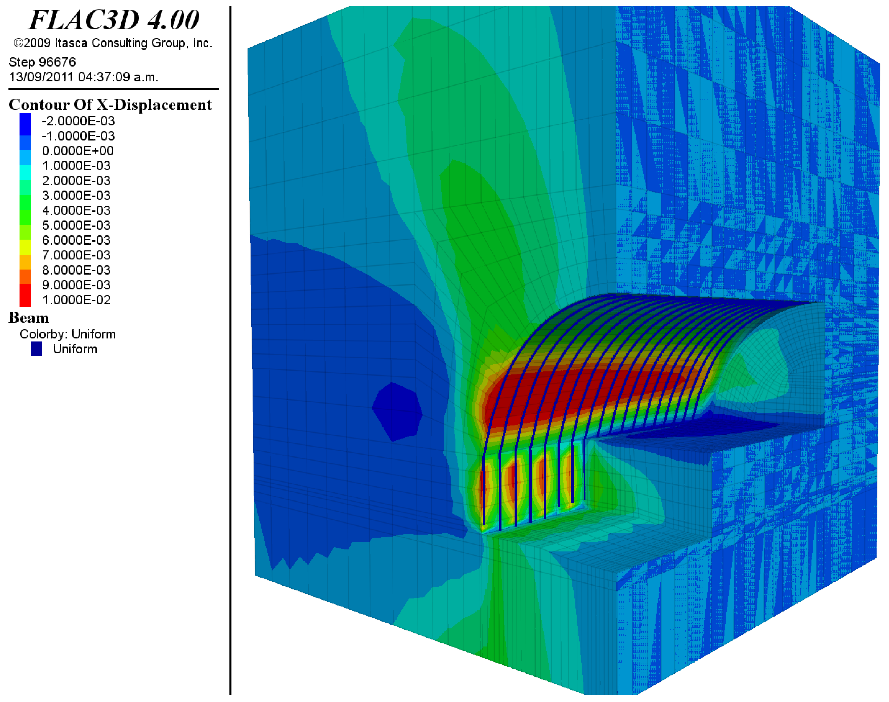
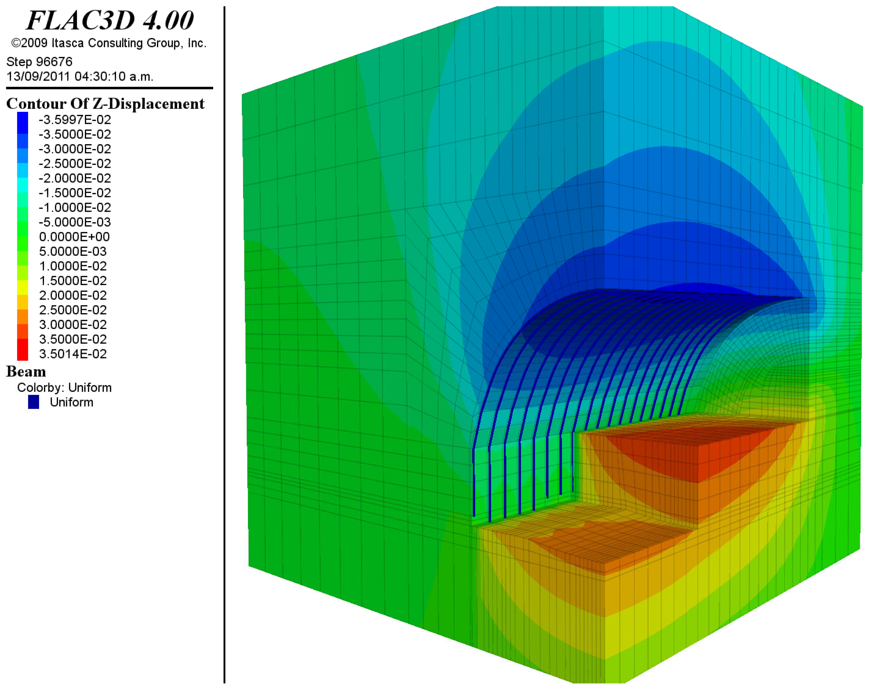
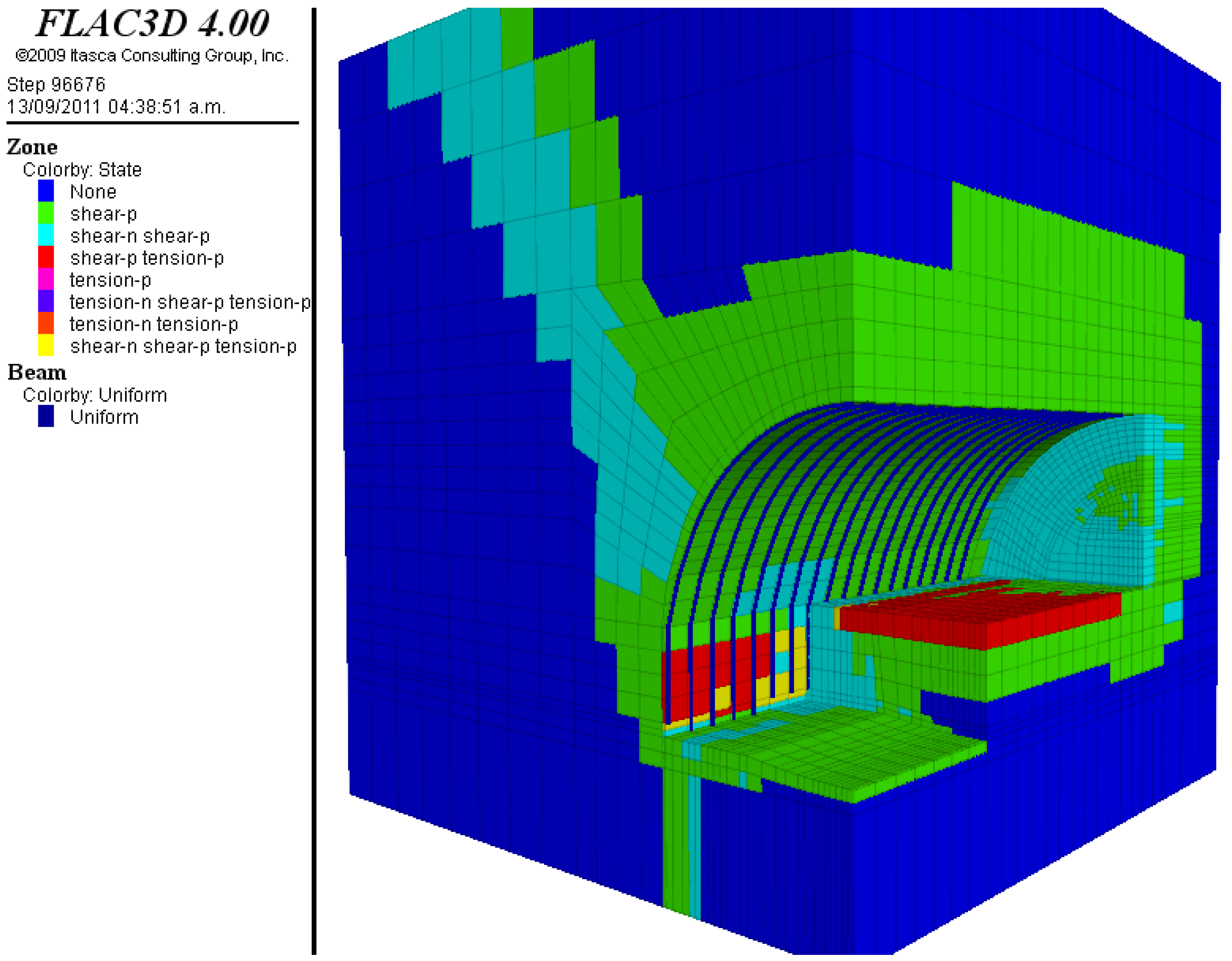
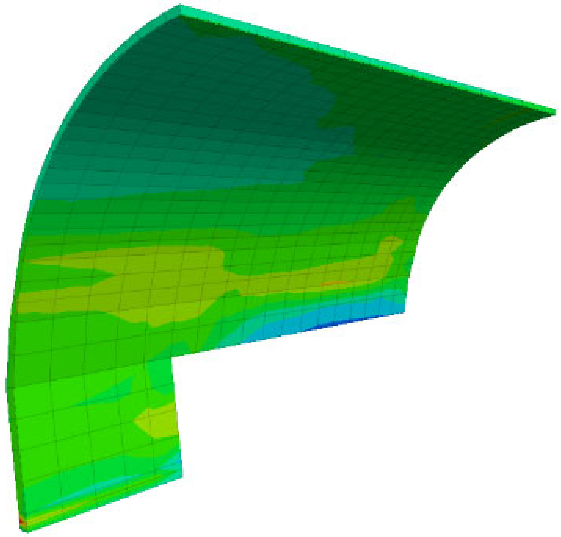
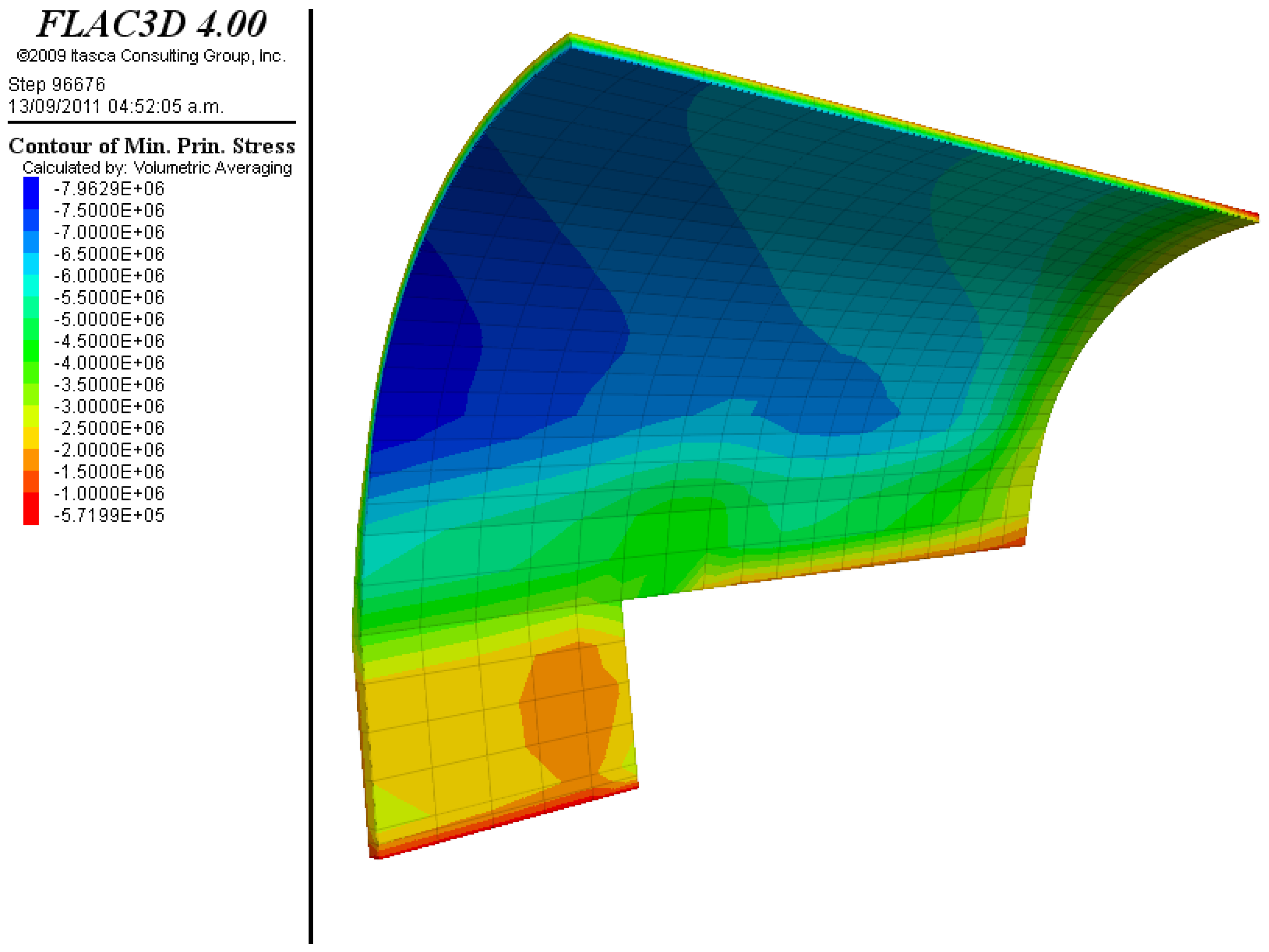
Figure 14 show some of the most notable results for a calculation phase with minimal parameters, in which the face is 30 m from the start of the excavation and the bench at 18 m.
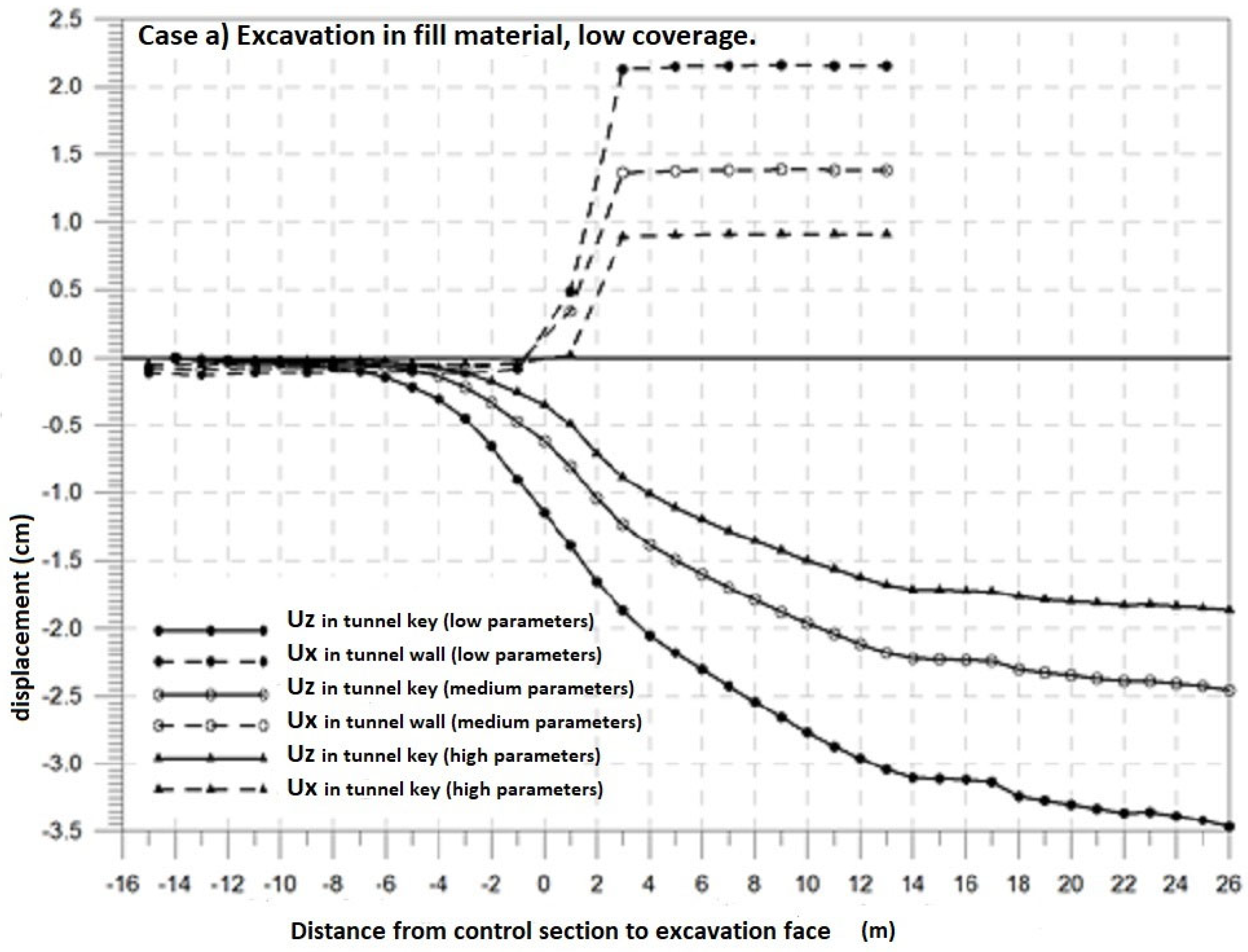
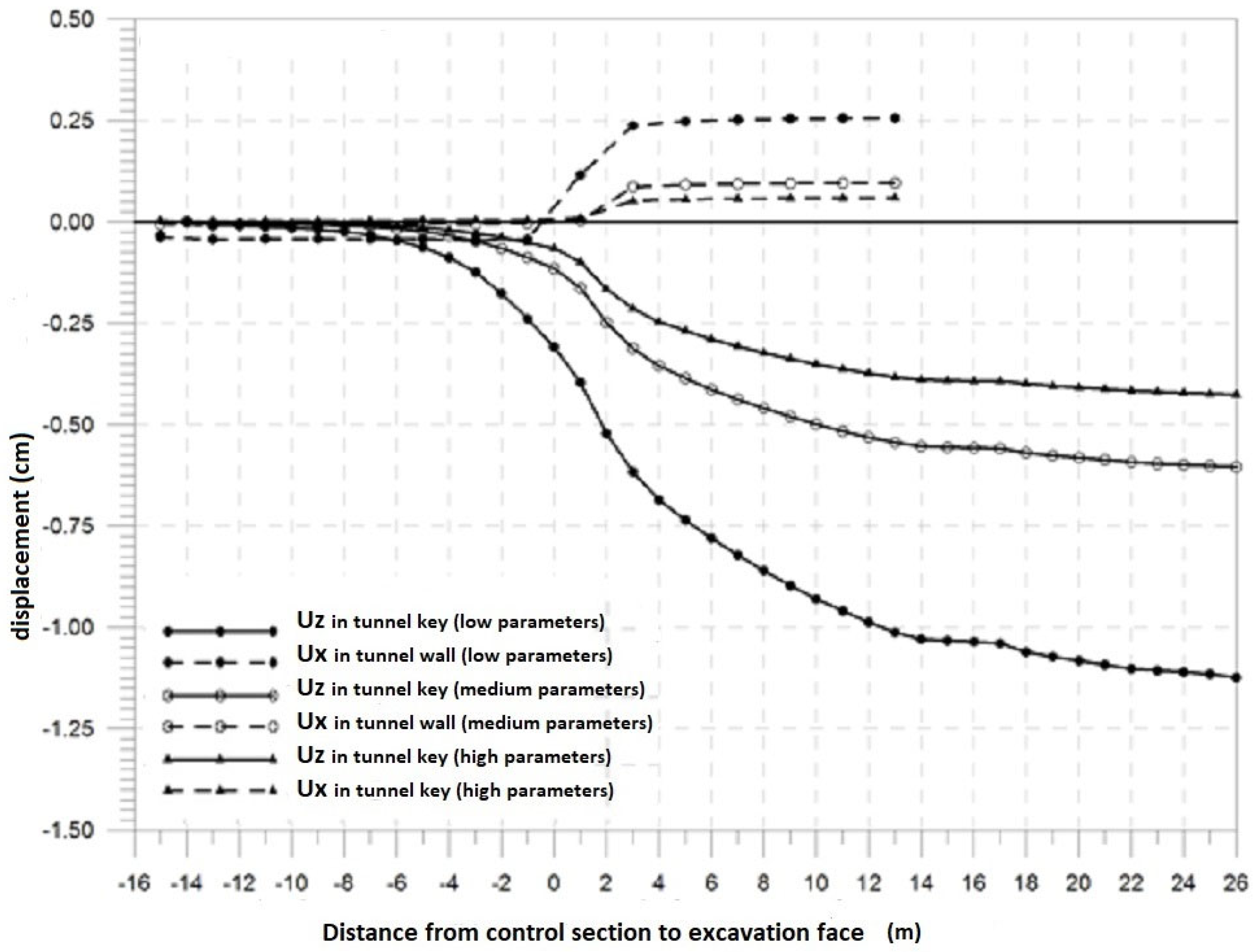
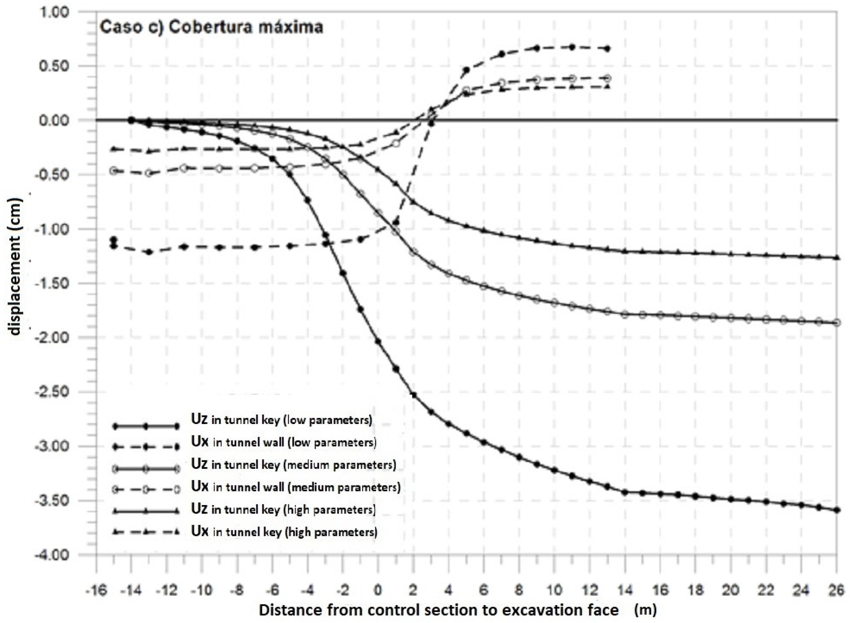
Figure 15 shows the evolution of the displacements in code (Uz) and gable (Ux) in a control section as the face of the excavation advances.
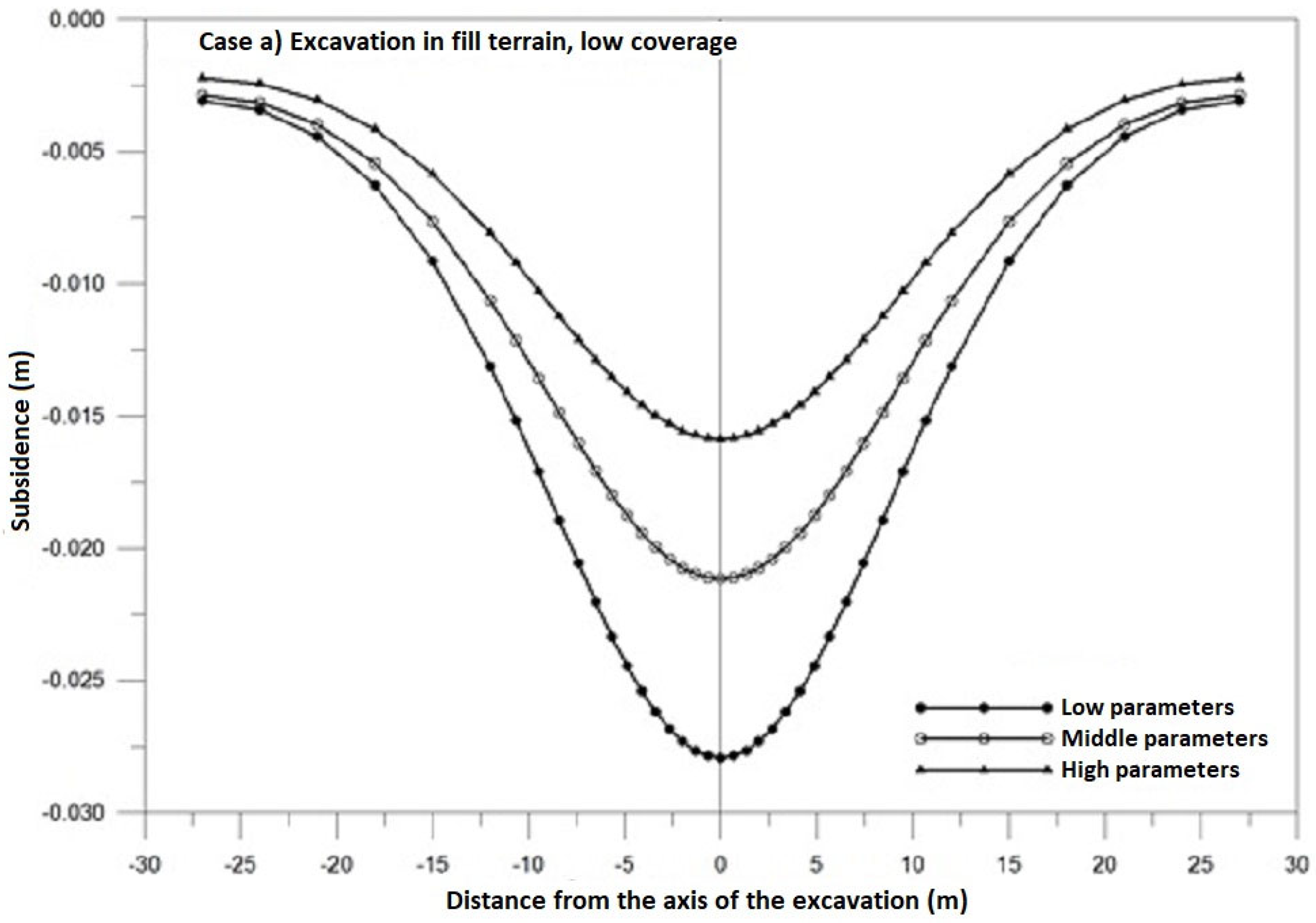
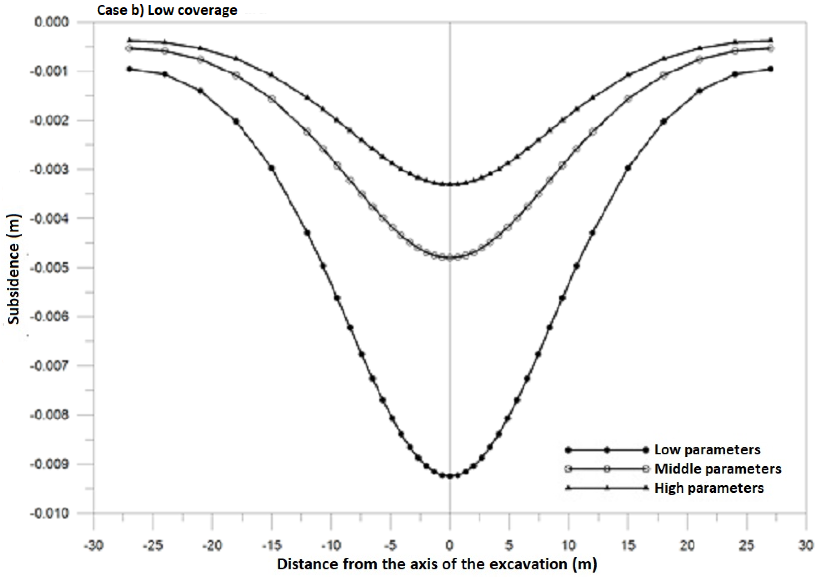
Figure 16 shows the settlement buckets at the end of the excavations, for a control section.
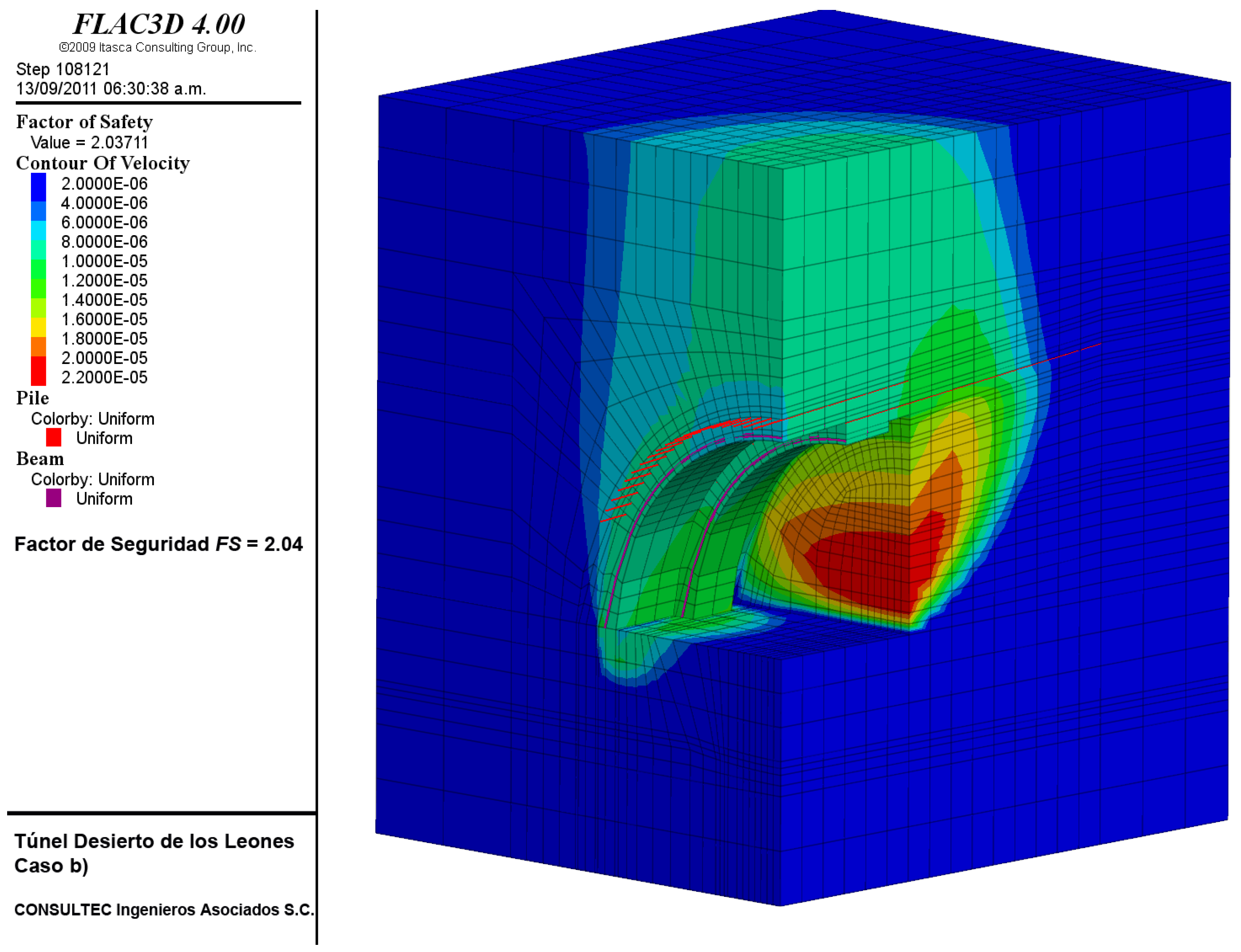
3.1.5. Excavation with Little Coverage in the Area near the South Portal
The simulation of the construction procedure case (b)
Figure 17 was carried out in the same way as in case (a). The finite difference mesh includes the strata of the pumitic series and the lower tuff. This case corresponds to the excavation in the South Portal area, once the landfill area has been passed. The ranges of values of the parameters used in the analysis correspond to those presented in
Table 2.
Figure 18,
Figure 19,
Figure 20,
Figure 21,
Figure 22 and
Figure 23 show some of the most notable results for a calculation phase with minimal parameters, in which the face is 30 m from the start of the excavation and the bench at 18 m.
Figure 24 shows the evolution of the displacements in code (Uz) and gable (Ux) in a control section as the face of the excavation advances.
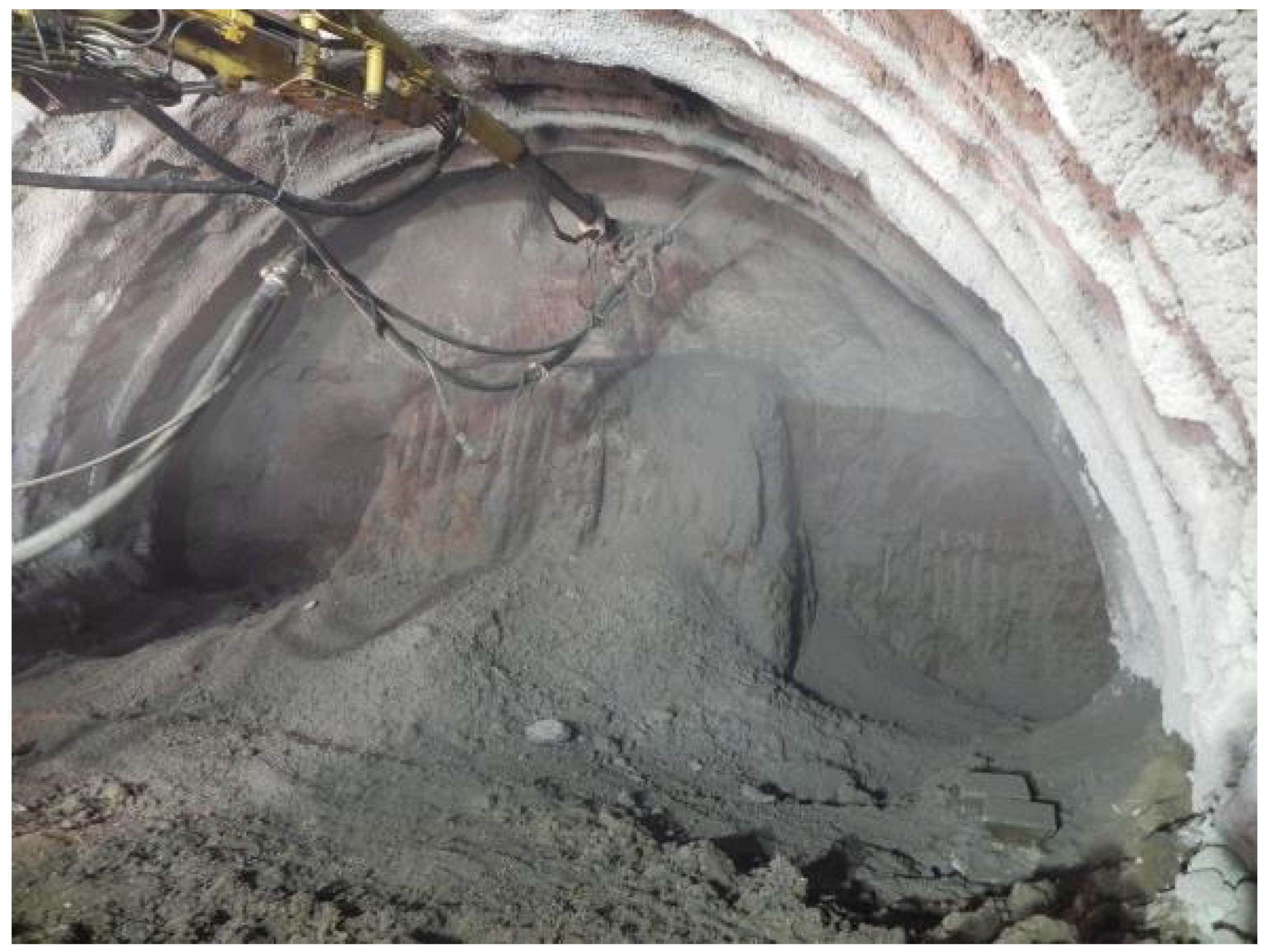
Settlement trays at the end of excavations for a control section are shown in
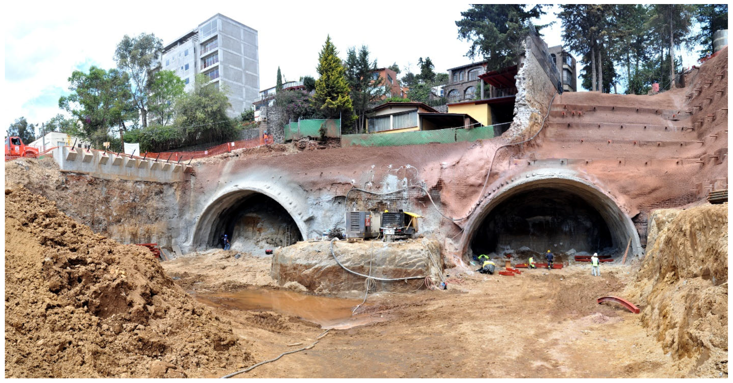
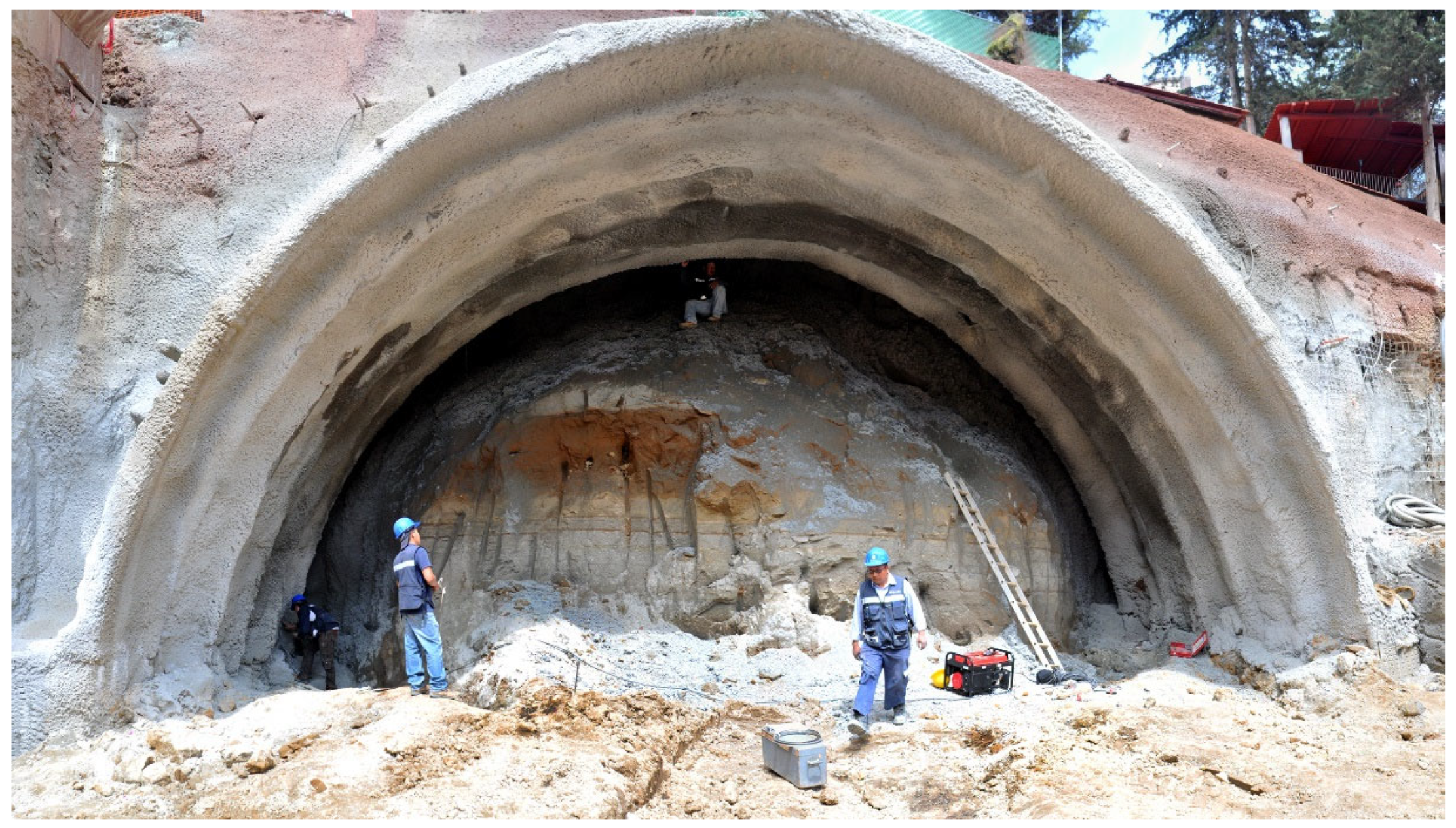
Figure 25. In the
Figure 26 and
Figure 27 is possible to see the terrain that was excavated in the South Portal.
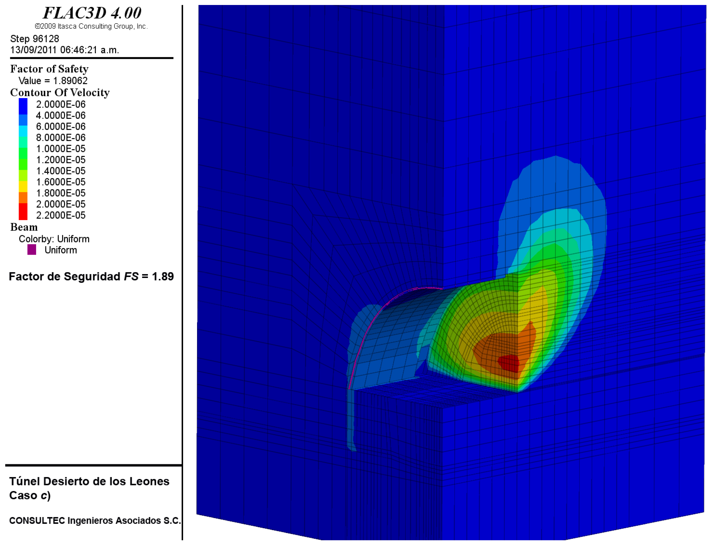
3.1.6. Excavation in the Area of Maximum Depth
In this case, the excavation will be conducted using the support of the ST-4 geotechnical condition, that consists of advances of the upper half section of 2.0 m by placing a sealing layer of 5 cm fiber-reinforced shotcrete, 29 TH- steel ribs and a second layer of shotcrete of 20 cm. The bank is also carried out in advances of 2.0 m.
The simulation of the construction procedure is carried out as follows:
- -
Creation of the initial state of efforts, considering the Jaky criterion for the definition of the horizontal component.
- -
Excavation of a 2.0 m advance from the upper half section.
- -
Placement of shotcrete and the TH-29 steel rib. Shotcrete has a stiffness and resistance typical of an age of 1 day.
- -
Next, advance of 2.0 m of the upper half section.
- -
Placement of shotcrete and the TH-29 steel rib. Shotcrete has a stiffness and resistance typical of an age of 1 day and the previous section of shotcrete evolves at an age of 2 days.
- -
Successive cycles until the upper half section has been completed.
- -
Bench advances 2 m.
- -
Placement of 1-day-old shotcrete and steel rib legs.
- -
Next bench advance.
- -
Placement of 1-day-old shotcrete and steel rib legs. The concrete of the previous phase reaches an age of 2 days and so on.
- -
Successive cycles until the tunnel is completed
Excavation analysis was carried out in a 30 m section with an average coverage of 30 m for three combinations of mechanical parameters (low, medium and high parameters) within the range defined for the pumitic and lower tuff series units (
Table 2).
3.2. Front Stability
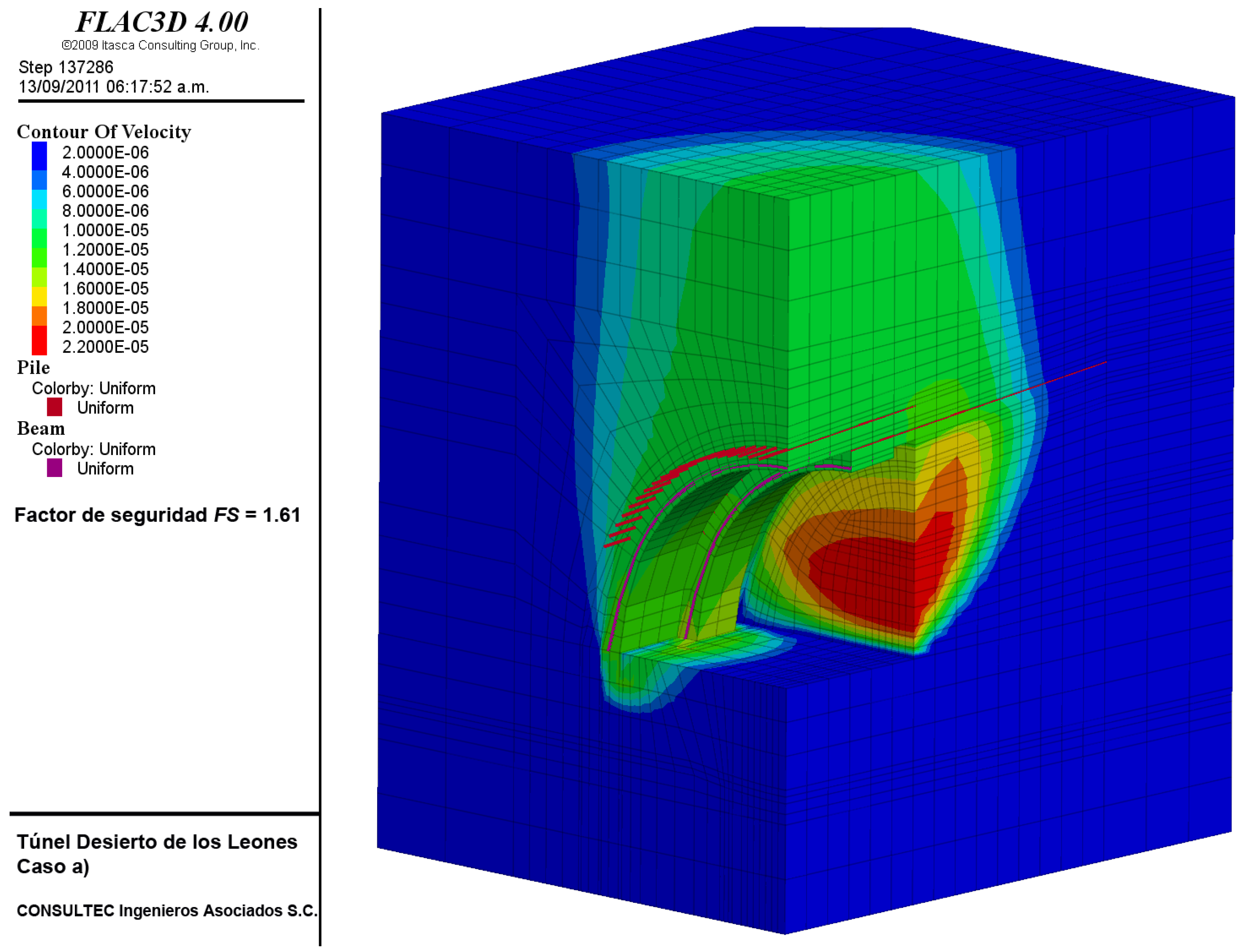
To study the stability of the model under the influence of the excavation procedure and the different support systems, the finite difference program we used has a calculation tool called Resistance Reduction Method. This tool reduces the resistance parameters in small steps until the model collapses, while the relationship between the decreased resistance and the original resistance is calculated, thus defining the concept of safety factor:
The relationship between true strength and the minimum calculated strength required for equilibrium is a very useful type of safety factor in geotechnics. To define the factor of safety in terms of the Mohr-Coulomb law of resistance we used:
Table 4 shows basic parameters for the front stability analysis and
Table 5 shows the results of the front stability calculations for the nine cases studied. In all cases, the state of stresses and deformations produced by the construction process were considered. In addition, all the elements of support are taken into account, including the different stiffness and strengths of concrete according to its age.
4. Discussion
The analyzes presented in this article provided a clear idea regarding the geotechnical conditions presented during the excavation
Figure 39 and were quite useful in preventing the different scenarios presented during the construction of the Desierto de los Leones tunnels.
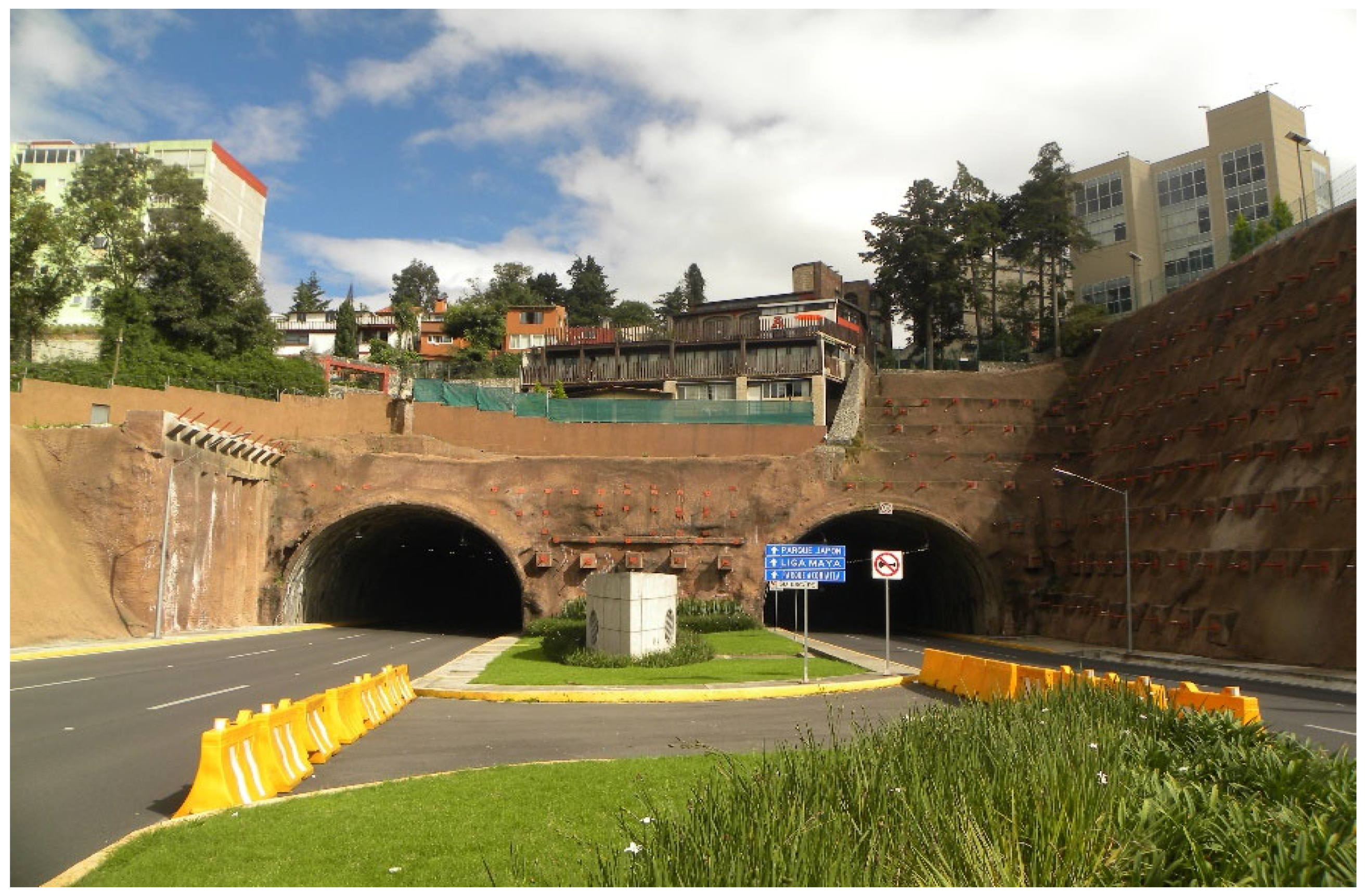
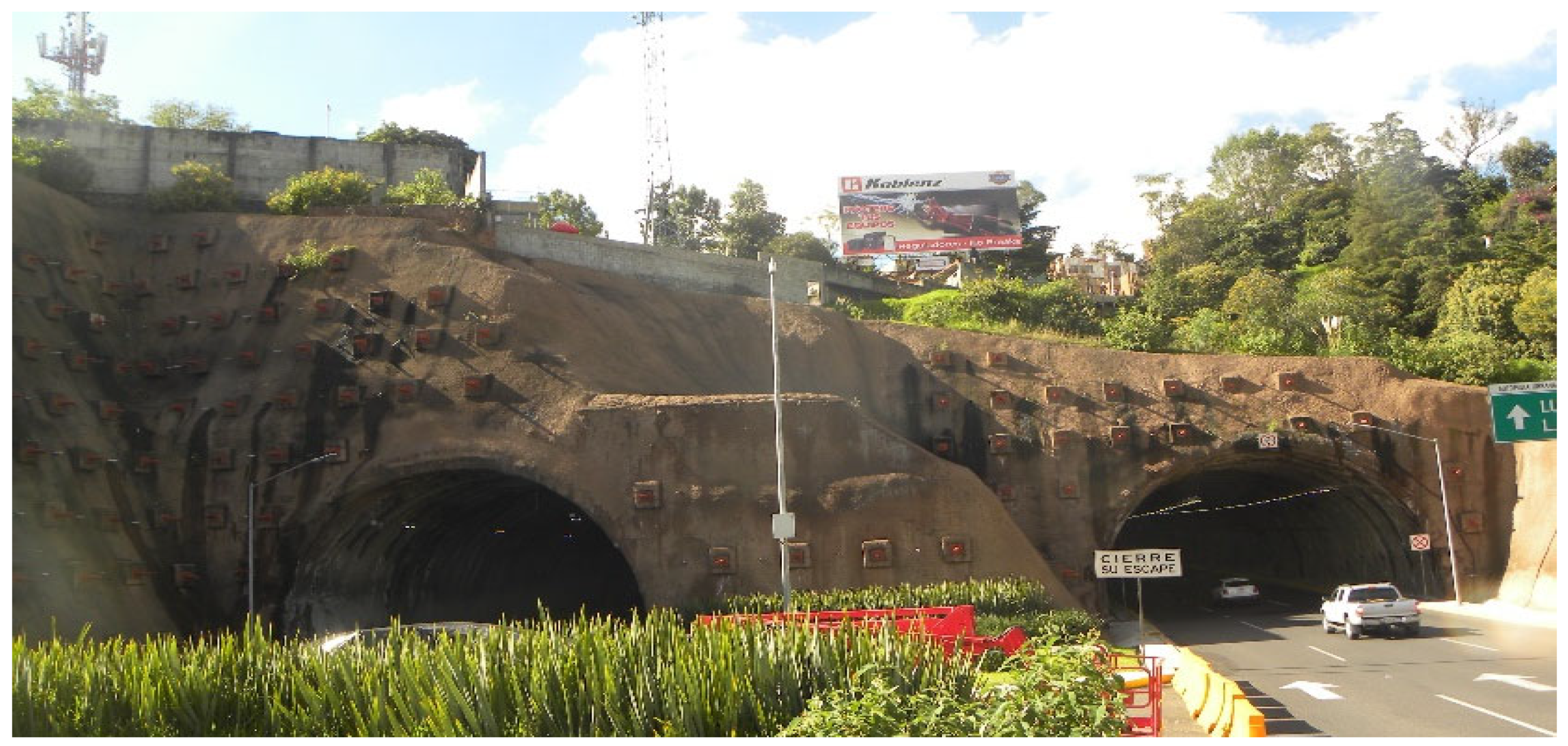
The results of the analyzes indicated that the possible displacement fields generated by the excavations could be of some importance. This occurred during the construction, especially around the portals, particularly in the South portal (the most critical), as a result of the lack of coverage, since houses are located a few meters from the mouth, as shown in
Figure 40. The North portal is shown in
Figure 41.
Due to the presence of structures on the surface and the magnitude of the calculated deformations, it was vitally important to carry out an exhaustive control of the convergences inside the tunnel and of the settlements on the surface, as well as of probable distortions in the houses present in the zone of influence of the tunnels. It is important to mention that the results of the site measurements were within the range of calculated displacements.
Regarding the safety levels in the construction of the tunnels, the results obtained and presented in this article were satisfactory and within the calculated ranges. This accounts for the fact that the analyzes were carried out only for the excavation and the supports. With the excavations completed and with the final lining implemented, the tunnels are currently in a condition of total stability and without any risk of collapse.
It is important to mention that the road began operations in 2013 and that an earthquake of 7.1 on the Richter scale occurred on 19 September 2017, in Mexico City [
18], causing severe damage and the collapse of several buildings. By mandate of the authorities of Mexico City, all infrastructure works were reviewed and evaluated, issuing an opinion on the security conditions after the earthquake. In the case of the Tunnel Desierto de los Leones, the opinion was satisfactory, and the tunnels currently operating normally. All the building above the tunnel (some of them only 8 m above the tunnel’s key) are in perfect condition without any damage.
5. Conclusions
The analyzes presented in this paper present different construction scenarios of the Desierto de los Leones tunnels. In accordance with the geotechnical conditions defined in the original project, they show that the considerations made during the study worked correctly at the time of the excavation.
The results indicate that the possible displacement fields generated by the excavations may be of some importance, although they are within the range of what commonly occurs in tunnels in soils excavated using traditional methods. Due to the presence of structures on the surface and the magnitude of the calculated deformations, it was vitally important to carry out an exhaustive control of the convergences inside the tunnel and of the settlements on the surface, as well as of probable distortions in the houses present above the tunnel. The area of influence of the tunnels confirmed the proposed hypotheses.
Regarding safety levels, the results obtained are satisfactory, especially since the analyzes were carried out only for the excavation and supports. As demonstrated, once the project was completed, the decisions implemented in the tunnels allowed them to be in a condition of total stability and without any risk of collapse.
It is important to emphasize that the models and calculations carried out for this study are based solely on the geological and geotechnical information present in the original project.
The best demonstration that the analysis model chosen to redesign the supports was correct is that it allowed the excavation to proceed without destroying or affecting the structures and buildings above the tunnel.


 ,
, 


