Article

PC-Allocation: Performance Cliff-Aware Two-Level Cache Resource Allocation Scheme for Storage System

School of Computer Science and Technology, Xi’an Jiaotong University, Xi’an 710049, China
*
Author to whom correspondence should be addressed.
Appl. Sci. 2023, 13(6), 3556; https://doi.org/10.3390/app13063556
Submission received: 1 February 2023 / Revised: 2 March 2023 / Accepted: 8 March 2023 / Published: 10 March 2023
(This article belongs to the Special Issue Advances in High-Performance Computing Research and Applications)

Abstract

:
Using the MRC (Miss Rate Curve) to guide cache capacity allocation is a common method in the storage system. However, optimal resource allocation is an NP-complete problem due to the cache performance cliff. Existing studies ignore this phenomenon or they use partitioning technology to eliminate it without considering the performance potential behind the cliff. This paper delves into this potential and proposes a cliff-aware cache resource allocation algorithm based on the inherent relationship between the capacity and the hit rate. Experiments show that these requests where the latency is less than 130 µs is increased by 33.3%. The proposed method obtains a significant cost reduction in DRAM and improves the hitting ratio of the cache layer.

1. Introduction

With the development of the information society and the continuous advancement of Internet technology, the amount of data worldwide are expanding. The DataAge 2025 report released in November 2018 points out that global data will increase from 33 ZB in 2018 to 175 ZB in 2025 [1]. Massive data are required to be stored reliably and accessed quickly. Using a low-latency cache is a common way to speed up the access on a backend large capacity storage system, and it could be used to improve the performance of many applications in many research fields, such as recent works published in [2,3,4,5,6]. Based on the access locality characterization of the program execution flow, the frequently accessed data is stored in a high-performance storage medium with a small capacity and high cost. Meanwhile, with the emergence of non-volatile memory and protocols, storage systems often use multi-layer caches with different storage characteristics to address varied kinds of storage requirements. Multi-tier caches widely exist in the storage system for various purposes, so the cache allocation algorithm has faced unsolved problems and has different design goals [7].
The cache replacement algorithm and capacity have great impacts on the cache performance. The former stipulates the promotion and evict rules between the cache frontend and the storage backend. Specifically, it refers to both the promotion time of back-end objects and the elimination time of promoted objects. The hit rate is the primary metric of the replacement algorithm, and the higher the hit rate, the better the performance. The LRU (Least Recently Used) algorithm is a classic cache replacement algorithm, and is widely used. Researchers have made many improvements on the LRU algorithm, such as 2Q [8], ARC [9], LIRS [10], and so on. However, in some cases, the experiments show that the hit rates of complex algorithms have obvious performance advantages when the capacity is small. Still, as the cache capacity increases, the hit rate gradually approaches the basic algorithm [11].
When the cache replacement algorithm is determined, the relationship between the hit rate and the capacity could be represented by the MRC (Miss Ratio Curve). Figure 1a shows the example where LRU is used as the cache replacement algorithm. Each point in the curves indicates the cache miss rate under a specific capacity. The X axis presents the cache capacity, and the Y axis presents the miss rate (the same as in the below figure, except where specifically indicated). In the initial stage, the miss rate at each point can only be calculated through the simulation program; the complete curve is finally obtained, and various research works have been carried out to solve this issue [12,13,14,15,16,17,18].
During the cache allocation phase, the algorithm must deal with the performance cliff phenomenon where a slight change in capacity will cause a huge variation in the miss rate. As shown in Figure 1b, the cache miss rate is stable between the capacity ranges <144 and 846>, and then in the interval of <846, 972>, the miss rate changes sharply. Performance cliffs have multiple effects on cache allocation. First, cliffs waste cache resources, and allocating caches in stable areas does not benefit the system performance. Secondly, cliffs can lead to unstable and unpredictable performance because small fluctuations in cache capacity can lead to a large performance cliff. Finally, the cliff makes the cache allocation very complicated [19]. The cliff phenomenon causes the MRC to have no convexity. At this time, the optimal allocation of the cache is an NP-complete problem [20].
The existing cache allocation methods either ignore the performance cliff or use partitioning technology to eliminate it [21,22,23,24,25] but these methods have evident drawbacks; the former lead to resource waste as the allocation granularity is not uniform, and the latter bring additional management overheads. The shortcomings of these schemes and the inherent potential benefits behind performance cliffs prompted us to propose a cliff-aware cache resource allocation algorithm. The contributions of this paper are as follows:
  • We model and analyze the potential of performance cliffs, and present the shortcomings of the two existing methods, and the unaware performance potential.
  • Based on an analysis result, we propose a cliff-aware cache allocation algorithm that takes the MRC as an input and calculates a cache allocation which satisfies the capacity or performance constraints.
  • We carefully compare the allocation results of the cliff-aware and the cliff-remove under various constraints, and validate the effectiveness of the proposed scheme.

2. Background and Motivation

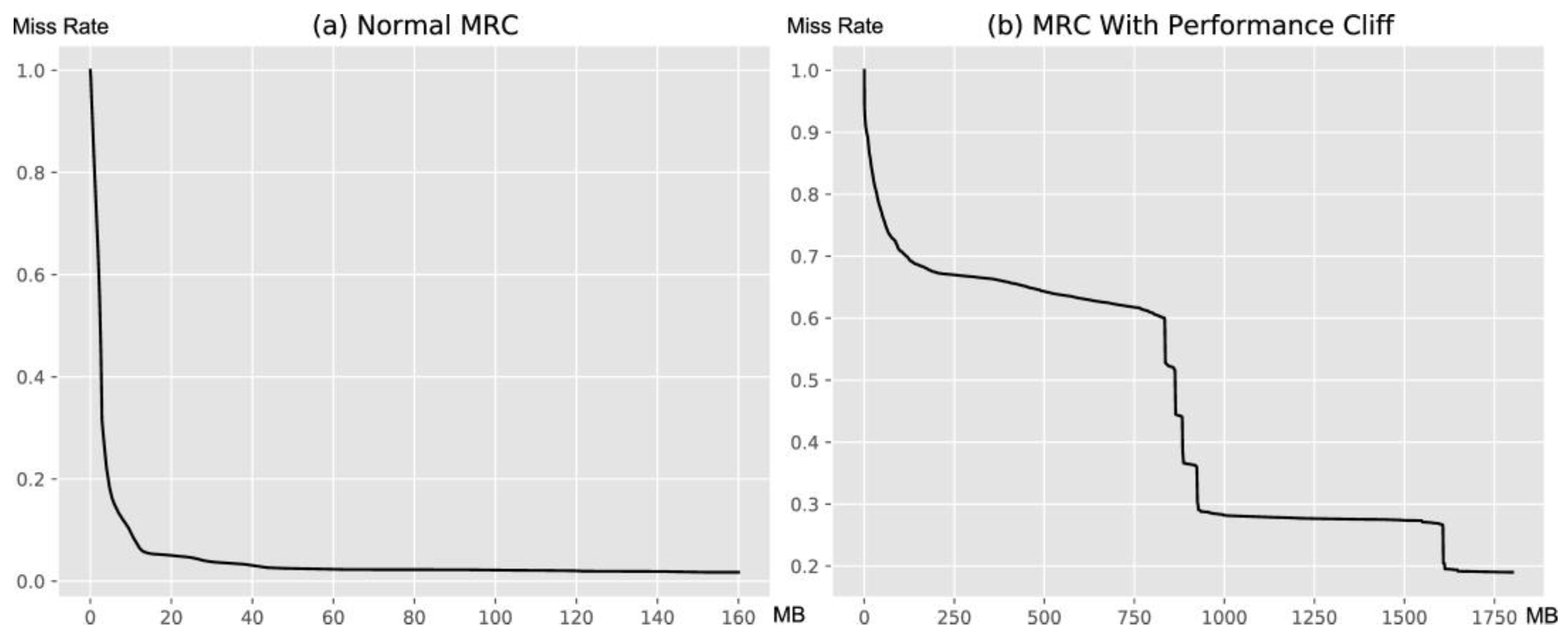
2.1. Cache Performance Cliff

As shown in Figure 1b, the performance cliff can be divided into stable and performance areas. In the stable area, the miss rate decreases slowly with the capacity increase. In contrast, and vice versa in the performance area, a slight change in the capacity causes a significant decrease in the miss rate. It reflects the uneven variation between the miss rate and the capacity. The reason for the cliff is closely related to the application access mode.
Existing studies use partition to remove the cache performance cliff. As shown in Figure 2a, the overall cache is divided into two independent regions, S1 and S2, and the request flows into the two partitions, respectively, according to the proportion ρ. Each partition has its own request flow and capacity; therefore, it also has own miss rate function, which is represented by m1(S1) and m2(S2). Due to the self- similarity of the request flow [14], the miss rate of the partition is related to the overall miss rate. Suppose that the sampling rate of the request flow is ρ, the m′(S′) of the partitions, and the original. The miss rate has the formulation shown in Equation (1) [19]:
m′(S′) ≈ ρm(S′/ρ).
Based on (1), the cache miss rate of each partition and the whole can be further calculated, as shown in Equation (2) [19]:
m1(S1) ≈ m(S1/ρ)
m2(S2) ≈ m((S1S2)/(1 − ρ))
m(S) ≈ ρm1(S1) + (1 − ρ)m2(S2).
On the basis of single-level cache-removal, Liu et al. [7] propose a multi-level cache performance cliff removal method, and its partition is shown in Figure 2b. This method improves on the performance of the cliff area, but it ignores the performance potential benefit behind, which will be analyzed in detail below.

2.2. Cliff Potential Performance Analysis

In this section, we show a simple example to analyze the performance potential mentioned above. As shown in Figure 3a, given that the access flow is ABCDABCDAB, the hit position is 4, so that when the capacity is less than or equal to 3, the miss rate is 1.0, and in other points, the miss rate is 0.4. There is a cliff between 0 and 4. This is assuming that the access is running in a two-layer cache which is composed of DRAM and SSD. Under the traditional cache architecture, the dram layer did not receive any hits, but if we reverse the hierarchy (SSD-DRAM) it can be found that the overall number of DRAM hits reached the limit, as shown in Figure 3b. The reason for this is that the performance area of the cliff has an effective cache hit.
For further explanation, the access element is increased from 4 to 8, and the request flow is expanded from 10 to 80. Now, we use the two-dimensional cliff removal method proposed in Section 2.1 to allocate cache resources, and calculate the times of cache hits for each layer. The overall cache capacity is 8, and so the feasible capacity combinations are (0, 8), (1, 7), (2, 6), (3, 5), (4, 4), (5, 3), (6, 2), (7, 1), and (8, 0). Since the convex hull of the original MRC curve contains only two points, σ1 and σ2 are both 0. It can be found from Table 1 that the DRAM layer hits increase as the capacity increases, but if we want to obtain the highest hit times, the DRAM capacity must be set to 8, which is the same as the traditional method at this time. However, when considering the position of the cliff, we can easily realize the same hit number by only setting the position to 8 in the cache as in the DRAM.
Based on this theory, we use the actual trace for further analysis. From the MSR Cambridge trace, we select proj_3 and hm_0 to construct MRC, as shown in Figure 4a. There is an obvious performance cliff between the 406 MB and the 540 MB capacity point in proj_3, and hm_0 does not contain the performance cliff, so that its MRC can be regarded as an approximate convex curve.
Figure 4b shows the performance gain difference between the miss rate when the capacity is increased by 64 kb. From the figure, the cache gain in the cliff performance area is significantly higher than that in the non-cliff area. Since there is no performance cliff in hm_0, except for the initial stage, no obvious performance gains are found.
The performance cliff is not friendly to traditional multi-level cache because high-performance media is at the top, and the front-end area of the MRC indicates its performance. The cache performance cliff contains a stable area, and its miss rate to capacity ratio is very low, but it occupies valuable high-performance cache resources. The overall hit rate is fixed when the total capacity remains the same. The better the top-level cache hit rate, the higher the cache performance. This relationship can be expressed by Equation (3); the overall delay of the cache layer is positively correlated with the hit rate of SSD. Since the speed difference between SSD and DRAM is too large, hdramtdram can be approximately ignored. Assuming that the value of tssd is fixed, the latency is proportional to hssd.
latency = hssdtssd + hdramtdramhssdtssdhssd
Now, we use three ways to allocate the cache for proj_3, using the proposed cliff-aware method. The result is shown in Figure 5. The green represents DRAM, and yellow represents the SSD. Using Equation (3) to measure the request delay, so we obtained latencyignore ≈ 0.512 tssd, latencyremoval ≈ 0.319 tssd, latencyaware ≈ 0.202 tssd. It is easy to find that the proposed cliff removal method can improve the hit rate in the initial stage, and that the cliff-aware method also does not change the overall hit rate, but that the DRMA area has a better hit rate ratio to capacity. This excellent ratio is the performance potential hidden behind the cliff, which has been ignored in previous studies.

3. The Design of the Cliff-Aware Cache Allocation Algorithm

This section introduces the cliff-aware cache resource allocation algorithm. The algorithm consists of two parts: cache performance cliff positioning and cache allocation.

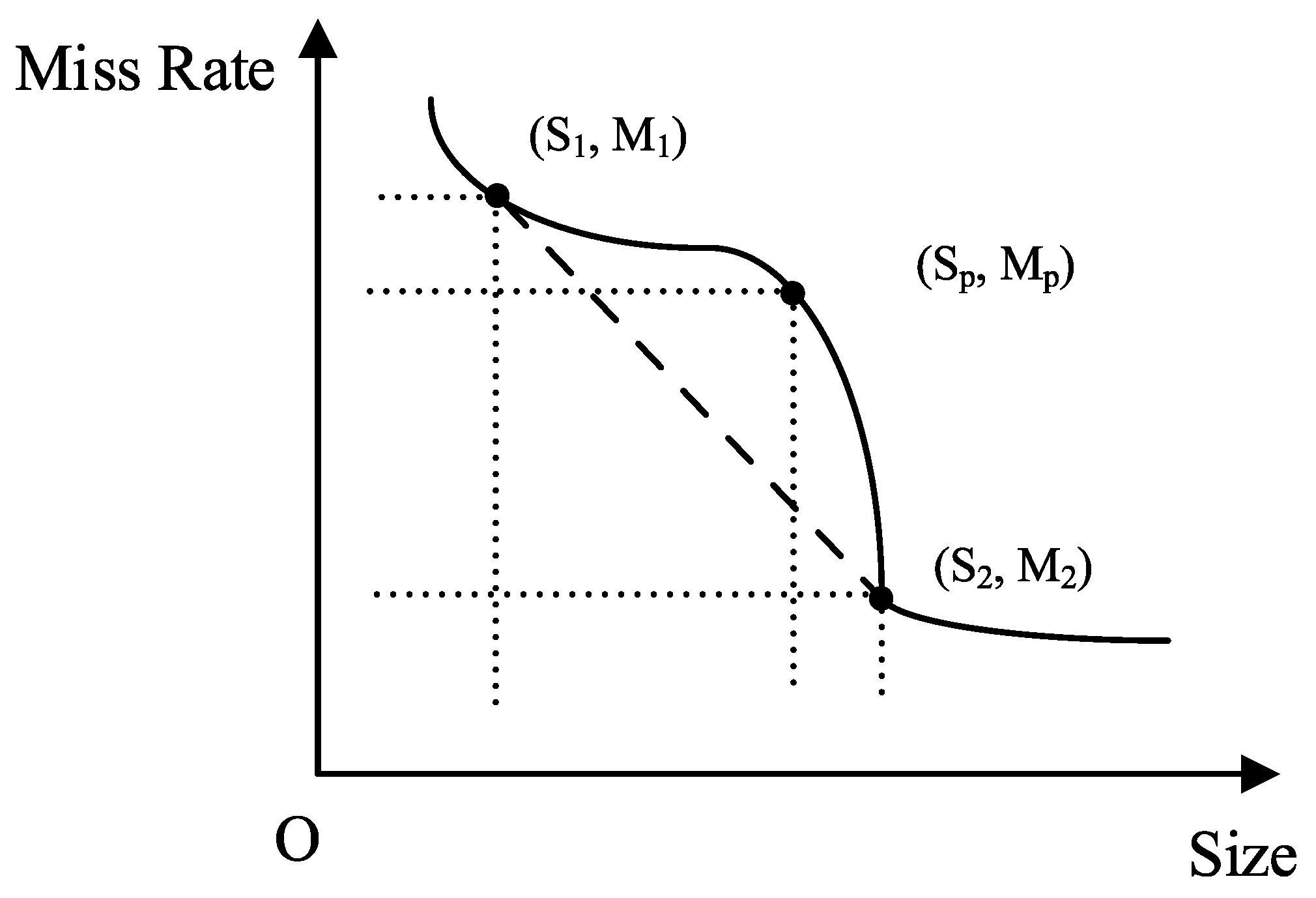
3.1. Cache Performance Cliff Positioning

The purpose of the positioning is to identify the starting point and the ending point of the cliff, according to the MRC. Since there are obvious capacity and cost changes in the cliff area, these two points must be included in the convex hull of MRC. This is because the MRC points are ordered (increasing capacity, decreasing miss rate), We can use the three coins algorithm to construct any MRC convex hull in O(N) time. After the convex hull is obtained, we judge all the adjacent points in the convex hull in turn, and find the neighboring nodes that satisfy Equation (4).
Si+1Sicliff_size_threshold
M(Si) − M(Si+1) ≥ cliff_hit_rate_threshold.
cliff_size_threshold and cliff_hit_rate_threshold are preset thresholds which can be adjusted manually. These two values determine the accuracy of cliff identification.
Changes in the capacity and hit rate are only necessary and insufficient conditions for the cliff. Accurate positioning also needs to find the turning point of the stable area and the performance area, as shown in Figure 6. First, the left and right endpoints of the capacity interval are connected by dotted line, and then all the capacity points in the interval are traversed to find the most significant point in the straight line and record that line as the turning point Sp.
capacity_proportion = SpS1/S2S1
hit_rate_proportion = M1Mp/M1M2.
The capacity_proportion parameter measures the position of Sp, the partition content, that is, the ratio of the capacity before the turning point to the overall capacity, and the hit_rate_proportion parameter measures the miss rate position of Sp the partition, that is, the ratio of the hit rate to the overall hit rate before the turning point. Similarly, both the capacity_proportion and the hit_rate_proportion have corresponding thresholds, which reflect the hit rate–capacity ratio of the cliff performance area, and need to be set according to the method published in [19].

3.2. Cliff-Aware Cache Allocation Algorithm

After obtaining the starting point, ending point, and turning point of the cliff, we use this information to allocate the cache. Only the first performance cliff is considered, to ensure that the number of cache layers is 2. The purpose of the algorithm is to find the smallest cost cache allocation that meets the performance requirements.
Based on the three points, we can obtain the initial cache allocation; the endpoint represents the overall cache capacity, the area between the turning point and the endpoint is DRAM, and between 0 and the turning point is SSD. The initial allocation is used to calculate cache performance and to compare it with the target performance. When the initial allocation performance is greater than the target performance, the overall capacity and DRAM capacity are reduced to lower the cost. Specifically, it refers to moving the DRAM area’s endpoint to the left to minimize the DRAM and overall capacity, then fixing the endpoint and moving the starting point of the DRAM area to the right. During this process, the overall performance and cost gradually decrease until the last allocation result that satisfies the constraint is found. the endpoints continue to be moved forward and all feasible endpoints are traversed. The minimum capacity allocation under each endpoint is found, and finally, the allocation result is obtained.
When the initial performance cannot reach what is expected, the overall capacity and DRAM capacity need to be increased to meet the performance requirements. Similar to the above process, the starting point of the DRAM area is moved forward, and the DRAM area is continuously expanded until the first capacity allocation that is greater than the target performance is found. The overall capacity is continuously increased, and we find the distribution result under each capacity. After obtaining all the results, we calculate the cost of each plan to obtain the lowest cost allocation plan.
The cliff-aware cache allocation algorithm is described in Algorithm 1; the detailed steps are as follows:
  • Collect application access characteristics to generate an MRC curve using the fixed space or fixed rate sampling method.
  • Generate a convex hull point set according to the MRC curve.
  • The allocation algorithm takes the convex hull set as input, and locates the cache cliff area from the convex hull set.
  • Locate the starting point, turning point, and ending point of the cliff in the cliff area. From the starting point to the turning point is a stable area, and from the turning point to the end point is a performance area. Traverse all feasible cache allocation schemes, and calculate the optimal allocation result of the performance function. The definition of the performance function is related to the cache capacity, cache cost, expected hit rate, etc.
The performance function has obvious differences in different cache usage scenarios. The best cache allocation scheme must be the way to obtain the extreme value of the performance function. In this paper, the cache cost is the lowest when the hit rate constraint of the performance function is given (constraints exist in both the first-level cache and the second-level cache). There are three schemes for cache allocation.
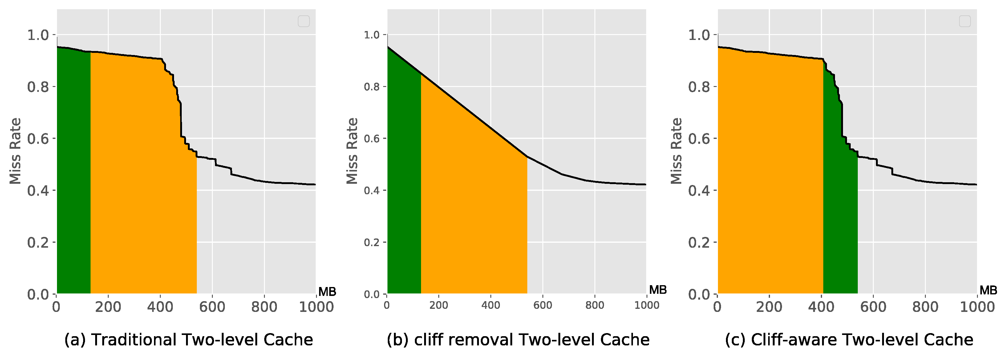
  • The plan of not doing any treatment. Directly according to the original MRC allocation, the allocation finds the first-level cache standard point and the second-level cache standard point, and the cost value at this time is the minimum cost.
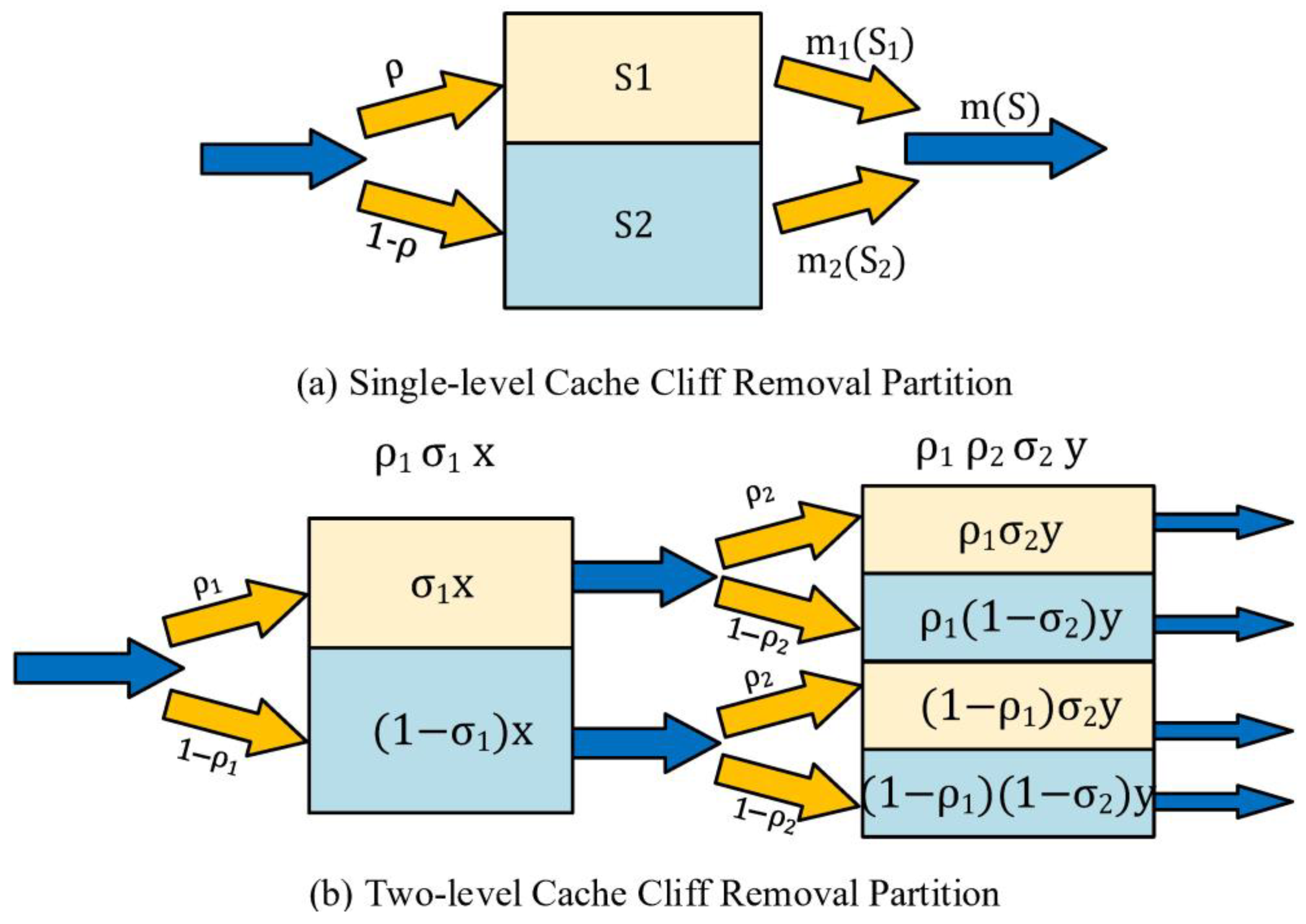
  • Cliff removal plan. Similar to (1), but first remove the performance cliff in the form of partitions, and then perform cache allocation and calculation accommodation.
  • Cliff perception assignment. Based on the cliff split point, expand the capacity forward or backward, and calculate the performance function. Complete the traversal of all feasible capacities.
According to the cliff and the turning point of the cliff, we can obtain the initial capacity allocation calculation method and calculate the SLO of the current cache allocation scheme.
When the initial performance is greater than the target performance, the capacity (overall capacity) needs to be reduced, that is, the shrinkage of the DRAM area. Fix the end point of the DMRA area, and continuously reduce the starting position (right_shrink) of the DMRA area until the critical point is reached that meets the SLO constraint. At this time, the SLO requirement cannot be met after the reduction, and the allocation plan is recorded at this time. Then, the end point of the DMRA area is moved to the left (left_shrink) by one unit, and the allocation with the smallest capacity under this end point continues to be calculated until all feasible end points are traversed.
When the initial performance is less than the target performance, the row capacity (overall capacity) needs to be improved. Similar to the above process, the operation is performed on the end point of the DRAM area until the capacity that meets the overall SLO requirements is found. After the end point is fixed, the operation is performed on the start point. During this process, the DRAM capacity increases and the performance improves. A point greater than the SLO is enough, and the operation is continuously performed on the end point to find all of the capacity division results.
When traversing all the allocation schemes, select the way with the lowest cost as the target cache allocation scheme.
Algorithm 1 Cliff-aware Cache Allocation Algorithm
Input:
SLO: The SLO target of the ith Application
cliff_begin: the starting position of performance cliff
cliff_end: the ending position of performance cliff
Output:
x: the desired DRAM capacity at least cost
y: the desired SSD capacity at least cost
B = []
M = 0
if performace(cliff_end−cliff_begin.,cliff_begin)) ≥ SLO  then
B.append(cliff_end−cliff_begin.,cliff_begin)
for m = cliff_end; m ≥ 0; left_shrink(m) do
for n = cliff_begin; n ≤ m; right_shrink(n) do
if performance(m − n, m) < SLO then
left_expand(n)
B.append(m − n, m)
break
end if
end for
end for
else:
  While (performace(cliff_end−cliff_begin.,cliff_begin))SLO)
  right_expand (cliff_end);
  for m = cliff_end; m ≤ max_cache_size; right_expand (m) do
  for n = cliff_begin; n ≥ 0; left_expand(n) do
if performance(m − n, m) ≥ SLO then
B.append(m − n, m)
break
end if
end for
end for
end if
x = B [0][0]
y = B [0][1]
min_cost = cost(x,y)
for i←1; i≤ B.size(); i++ do
  if cost(B[i][0], B[i][1]) < min_cost then:
  min_cost = cost(B[i][0], B[i][1]
  x = B[i][0]
   y = B[i][1]
  end if
end for
return x, y

3.3. Constraints

Although the new allocation brings significant performance improvements, this method has some constraints. First, the new allocation treats the two-level cache as a whole, which means that the two layers should use the same cache replacement algorithm with stack attribute. Secondly, the starting position of the DRAM area is in the performance area of the cliff, and the ending position represents the overall capacity. This means that when the overall capacity of the cache increases, the DRAM capacity increases and the SSD capacity is relatively fixed. After the cliff area is over, an additional DRAM capacity cannot bring a higher performance. Therefore, the overall benefit of this allocation method will gradually decrease and eventually disappear, which means that the program is a partial optimization. Finally, the new allocation method is only applicable to scenes that contain performance cliffs, and is invalid in other scenes.

4. Experimental Methodology

In this section, the algorithm mentioned above is evaluated. The experiment is divided into two parts. First, we analyze and compare the allocation results of the cliff removal and the cliff-aware algorithm under different cost and performance constraints. Second, we revisit part of the trace on the real disk to compare the actual effect.

4.1. Minimum Cost Cache Allocation

For a fair comparison, we use the min-cost as an indicator proposed by Liu [7]. We select traces with cliffs from MSR, including proj_2 and usr_1 [26]. For every selected trace, the maximum cache size is the working set size, and the minimum is the starting point of the cliff performance area. The area between these two capacities is divided into 50 equally spaced intervals, so that we have a total of 51 capacity constraints. Under each capacity constraint, we calculate the maximum (only use DRAM) and the minimum performances (only use SSD), and then we take 9 performance points at equal intervals between the max–min performance, for a total of 11 performance points. For each capacity and performance constraint, we calculate the results of the cliff removal and the cliff-aware algorithm. The algorithm parameters are shown in the Table 2. We use Equation (6) to calculate the cost difference between the two allocation results.
diff = (costawarecostremove)/costremove,
The result of proj_2 is shown in Figure 7 with the form of a heat map. The blue area indicates that the cliff-aware algorithm has achieved a lower cache cost; however, the red area manifests that the cliff removal algorithm has a cost advantage. From the distribution of the blue area, it is easily found that the dominant area of the cliff-aware algorithm is closely related to the position of the cliff. At the end area of the cliff (204,832), our algorithm has obtained a significant cost reduction, and then with performance requirements and the overall capacity increases, these kinds of advantages gradually decrease. In the area far away behind the cliff (321,845), there is a small blue area, because in the original MRC, there has a significant increase in the miss rate, which can be treated as an approximated performance area, so that the place for this part of the capacity in the high-speed cache can make a profit.
In addition, there are purple areas in the heat map, which indicates the cliff-aware algorithm is invalid. This is because the cliff removal can provide a higher cache hit rate under the same capacity. The max IOPS is calculated based on this hit rate, with all cache capacities as DRAM, so that even if our algorithm can obtain the same DRAM size but cannot realize the same hit rate, the performance requirements cannot be met.
However, cliff-aware algorithms are not always effective. Figure 8 shows the allocation results of usr_1, whose performance area is <307,096, 373,856>. We observe that the cliff-aware distribution method does not reduce the cache cost in any capacity or performance constraints. The reason for this is that usr_1 has approximately vertical cache benefits at the initial area. Essentially, the cliff-aware algorithm is based on the phenomenon that the cliff performance area has a higher cache benefit than the MRC starting area, even if the cliff is removed sometimes, but if the revenue does not exist or is very small, the cliff-aware method cannot obtain a better result.

4.2. Running on Real Devices

Figure 9 shows the cumulative latency probability curve of the two allocation methods. The green area represents the cliff-remove method, and the orange area represents the cliff-aware method. It is obvious that the cliff-aware method has a greater percentage of low-latency request finish times; the proportion of requests with a finish time of less than 130 µs is increased by 33.3% (from 0.6 to 0.8). This is consistent with expectations that the cliff-aware method provides a better hit benefit with the same hit rate.

5. Conclusions

The cache performance cliff is a phenomenon that is closely related to application access patterns, which leads to a non-convex MRC, and it has been found that the optimal allocation under non-convex curves is an NP-complete problem. Existing studies use partition technology to eliminate it, but these techniques ignore the access hot spot contained in the cliff area. We carefully studied the hidden performance potential behind the cliff, and proposed a cliff-aware cache resource allocation algorithm and detailed testing cliff-remove and cliff-aware methods under different capacity and performance constraints. Lastly, based on real hardware, we further implemented a DRAM-SSD two-level cache prototype system to compare the differences between the two allocation methods, and validated the effectiveness of our proposed scheme. This still leaves some chances for studying in future research, and we will try to exploit the characterization of non-volatile memory to cooperate with DRAM as a front-end cache to improve the storage performance.

Author Contributions

Conceptualization, S.L. and C.Z.; formal analysis, S.L.; experiment, C.Z., S.N., and K.D.; writing—original draft preparation, C.Z. and S.N.; writing—review and editing, S.L.; visualization, K.D.; supervision, W.W.; project administration, W.W. All authors have read and agreed to the published version of the manuscript.

Funding

This research was funded by the National Natural Science Foundation of China (No. 62002279 and No. 61972311), the Natural Science Basic Research Program of Shaanxi (Program No. 2020JQ-077), and the Shandong Provincial Natural Science Foundation (No. ZR2021LZH009).

Institutional Review Board Statement

Not applicable.

Informed Consent Statement

Not applicable.

Data Availability Statement

Not applicable.

Conflicts of Interest

The authors declare no conflict of interest.

References

  1. Reinsel, D.; Gantz, J.; Rydning, J. Data Age 2025: The Evolution of Data to Life-Critical Don’t Focus on Big Data; IDC Analyze the Future: Framingham, MA, USA, 2017. [Google Scholar]
  2. Mastour, N.; Jemaï, M.; Ridene, S. Calculation of ground state and Hartree energies of MoS2/WSe2 assembled type II quantum well. Micro Nanostruct. 2022, 171, 207417. [Google Scholar] [CrossRef]
  3. Mastour, N.; Ramachandran, K.; Ridene, S.; Daoudi, K.; Gaidi, M. Tailoring the optical band gap of In–Sn–Zn–O (ITZO) nanostructures with co-doping process on ZnO crystal system: An experimental and theoretical validation. Eur. Phys. J. Plus 2022, 137, 1137. [Google Scholar] [CrossRef]
  4. Jlidi, Z.; Baachaoui, S.; Raouafi, N.; Ridene, S. Temperature effect on structural, morphological and optical properties of 2D-MoS2 layers: An experimental and theoretical study. Optik 2021, 228, 166166. [Google Scholar] [CrossRef]
  5. Górski, T.; WOźniak, A.P. Optimization of Business Process Execution in Services Architecture: A Systematic Literature Review. IEEE Access 2021, 9, 111833–111852. [Google Scholar] [CrossRef]
  6. Saboor, A.; Hassan, M.F.; Akbar, R.; Shah, S.N.M.; Hassan, F.; Magsi, S.A.; Siddiqui, M.A. Containerized Microservices Orchestration and Provisioning in Cloud Computing: A Conceptual Framework and Future Perspectives. Appl. Sci. 2022, 12, 5793. [Google Scholar] [CrossRef]
  7. Liu, Z.; Lee, H.W.; Xiang, Y.; Grunwald, D.; Ha, S. eMRC: Efficient Miss Ratio Approximation for Multi-Tier Caching. In Proceedings of the FAST, Virtual, 23–25 February 2021; pp. 293–306. Available online: https://www.usenix.org/conference/fast21/presentation/liu (accessed on 1 January 2023).
  8. Shasha, D.; Johnson, T. 2q: A low overhead high performance buffer management replacement algorithm. In Proceedings of the 20th International Conference on Very Large Data Bases, New York, NY, USA, 12 September 1994; pp. 439–450. [Google Scholar]
  9. Megiddo, N.; Modha, D.S. ARC: A Self-Tuning, Low Overhead Replacement Cache. In Proceedings of the FAST ’03 Conference, San Francisco, CA, USA, 31 March–2 April 2003; Volume 3, pp. 115–130. [Google Scholar] [CrossRef]
  10. Jiang, S.; Zhang, X. LIRS: An efficient low inter-reference recency set replacement policy to improve buffer cache performance. ACM Sigmetr. Perform. Eval. Rev. 2002, 30, 31–42. [Google Scholar] [CrossRef]
  11. Zhou, K.; Sun, S.; Wang, H.; Huang, P.; He, X.; Lan, R.; Li, W.; Liu, W.; Yang, T. Demystifying cache policies for photo stores at scale: A tencent case study. In Proceedings of the 2018 International Conference on Supercomputing, Beijing, China, 12–15 June 2018; pp. 284–294. [Google Scholar] [CrossRef]
  12. Mattson, R.L.; Gecsei, J.; Slutz, D.R.; Traiger, I.L. Evaluation techniques for storage hierarchies. IBM Syst. J. 1970, 9, 78–117. [Google Scholar] [CrossRef]
  13. Niu, Q.; Dinan, J.; Lu, Q.; Sadayappan, P. PARDA: A fast parallel reuse distance analysis algorithm. In Proceedings of the 2012 IEEE 26th International Parallel and Distributed Processing Symposium, Shanghai, China, 21–25 May 2012; pp. 1284–1294. [Google Scholar] [CrossRef]
  14. Waldspurger, C.A.; Park, N.; Garthwaite, A.T.; Ahmad, I. Efficient MRC Construction with SHARDS. In Proceedings of the FAST, Santa Clara, CA, USA, 16–19 February 2015; Volume 15, pp. 95–110. [Google Scholar] [CrossRef]
  15. Carra, D.; Neglia, G. Efficient miss ratio curve computation for heterogeneous content popularity. In Proceedings of the 2020 USENIX Conference on Usenix Annual Technical Conference, Rome, Italy, 15–17 July 2020; pp. 741–751. [Google Scholar] [CrossRef]
  16. Waldspurger, C.A.; Saemundsson, T.; Ahmad, I.; Park, N. Cache Modeling and Optimization using Miniature Simulations. In Proceedings of the USENIX Annual Technical Conference, Santa Clara, CA, USA, 12–14 July 2017; pp. 487–498. [Google Scholar] [CrossRef]
  17. Hu, X.; Wang, X.; Zhou, L.; Luo, Y.; Wang, Z.; Ding, C.; Ye, C. Fast miss ratio curve modeling for storage cache. ACM Trans. Storage (TOS) 2018, 14, 1–34. [Google Scholar] [CrossRef]
  18. Zhang, Y.; Huang, P.; Zhou, K.; Wang, H.; Hu, J.; Ji, Y.; Cheng, B. OSCA: An online-model based cache allocation scheme in cloud block storage systems. In Proceedings of the 2020 USENIX Conference on Usenix Annual Technical Conference, Online, 15–17 July 2020; pp. 785–798. [Google Scholar] [CrossRef]
  19. Beckmann, N.; Sanchez, D. Talus: A simple way to remove cliffs in cache performance. In Proceedings of the 2015 IEEE 21st International Symposium on High Performance Computer Architecture (HPCA), Huazhong, China, 15–17 July 2020; pp. 64–75. [Google Scholar] [CrossRef] [Green Version]
  20. Yang, J.; Wang, Y.; Wang, Z. Efficient modeling of random sampling-based lru. In Proceedings of the 50th International Conference on Parallel Processing, Lemont, IL, USA, 9–12 August 2021; pp. 1–11. [Google Scholar] [CrossRef]
  21. Arteaga, D.; Ahmad, I.; Cabrera, J.; Jun, S.; Xu, J.; Xu, S.; Sundararaman, S.; Zhao, M.; Zhen, S.; Tarasov, V.; et al. Cloudcache: On-demand flash cache management for cloud computing. In Proceedings of the 14th USENIX Conference on File and Storage Technologies (FAST 16), Santa Clara, CA, USA, 22–25 February 2016; pp. 355–369. [Google Scholar] [CrossRef]
  22. Prabhakar, R.; Srikantaiah, S.; Patrick, C.; Kandemir, M. Dynamic storage cache allocation in multi-server architectures. In Proceedings of the Conference on High Performance Computing Networking, Storage and Analysis, Portland, OR, USA, 14–20 November 2009; pp. 1–12. [Google Scholar] [CrossRef]
  23. Cidon, A.; Eisenman, A.; Alizadeh, M.; Katti, S. Cliffhanger: Scaling performance cliffs in web memory caches. In Proceedings of the 13th USENIX Symposium on Networked Systems Design and Implementation (NSDI 16), Santa Clara, CA, USA, 17–18 March 2016; pp. 379–392. [Google Scholar] [CrossRef]
  24. Rajasekaran, S.; Duan, S.; Zhang, W.; Wood, T. Multi-cache: Dynamic, efficient partitioning for multi-tier caches in consolidated VM environments. In Proceedings of the 2016 IEEE International Conference on Cloud Engineering (IC2E), Berlin, Germany, 4–8 April 2016; pp. 182–191. [Google Scholar] [CrossRef]
  25. Meng, F.; Zhou, L.; Ma, X.; Uttamchandani, S.; Liu, D. vCacheShare: Automated Server Flash Cache Space Management in a Virtualization Environment. In Proceedings of the USENIX Annual Technical Conference, Philadelphia, PA, USA, 19–20 June 2014; pp. 133–144. [Google Scholar] [CrossRef]
  26. Narayanan, D.; Donnelly, A.; Rowstron, A. Write off-loading: Practical power management for enterprise storage. ACM Trans. Storage (TOS) 2008, 4, 1–23. [Google Scholar] [CrossRef]
Figure 1. The example of MRC in multi-cache storage system.
Applsci 13 03556 g001
Figure 2. Partition Scheme to Eliminate the Cache Performance Cliff [7,19].
Applsci 13 03556 g002
Figure 3. Access characterization of Performance Cliff.
Applsci 13 03556 g003
Figure 4. Cache Performance Gains as Capacity Increases.
Applsci 13 03556 g004
Figure 5. Comparison of three cache allocation.
Applsci 13 03556 g005
Figure 6. The Example of Partition Point.
Applsci 13 03556 g006
Figure 7. The Allocation Results of proj_2.
Applsci 13 03556 g007
Figure 8. The Allocation Results of usr_1.
Applsci 13 03556 g008
Figure 9. Probability Cumulative Curve of Request Latency (µs).
Applsci 13 03556 g009
Table 1. DRAM layer hits under each capacity.
Capacityρ1σ1ρ2σ2DRAM Hit
(0, 8) 0
(1, 7)0.87500.37509
(2, 6)0.7500.509
(3, 5)0.62500.375018
(4, 4)0.500.5036
(5, 3)0.37500.625036
(6, 2)0.2500.7509
(7, 1)0.12500.875063
(8, 0) 0
Table 2. The algorithm parameters.
ParameterValue
cliff_size_threshold0.2
cliff_hit_rate_threshold0.4
capacity_proportion0.6
hit_rate_proportion0.4
Disclaimer/Publisher’s Note: The statements, opinions and data contained in all publications are solely those of the individual author(s) and contributor(s) and not of MDPI and/or the editor(s). MDPI and/or the editor(s) disclaim responsibility for any injury to people or property resulting from any ideas, methods, instructions or products referred to in the content.

