Author Contributions
Conceptualization, D.R., C.M., and W.J.; methodology, D.R., W.J., and G.B.; software, D.R. and C.M.; validation, D.R. and C.M.; formal analysis, D.R. and W.J.; investigation, D.R.; resources, W.J., J.R., J.A.T., and G.B.; data curation, D.R. and C.M.; writing—original draft preparation, D.R., C.M., W.J., G.B., and J.R.; writing—review and editing, D.R., W.J., G.B., and J.A.T.; visualization, D.R.; supervision, W.J., J.A.T., and G.B.; project administration, W.J.; funding acquisition, W.J., J.R., and G.B. All authors have read and agreed to the published version of the manuscript.
Figure 1.
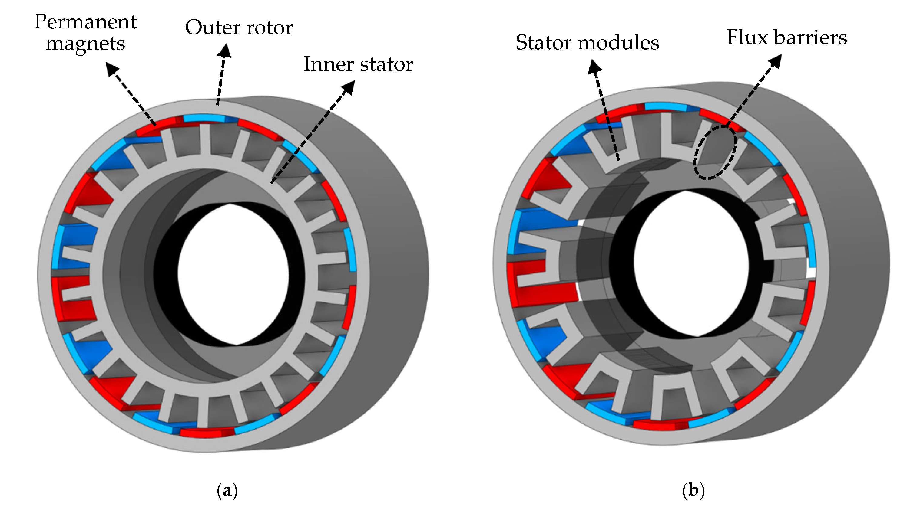
Three-dimensional representation of stator/rotor structure of a 24-slot, 20-pole PMSM: (a) conventional PMSM with non-segmented stator (monolithic), (b) PMSM with modular stator core (MPMSM).
Figure 1.
Three-dimensional representation of stator/rotor structure of a 24-slot, 20-pole PMSM: (a) conventional PMSM with non-segmented stator (monolithic), (b) PMSM with modular stator core (MPMSM).
Figure 2.
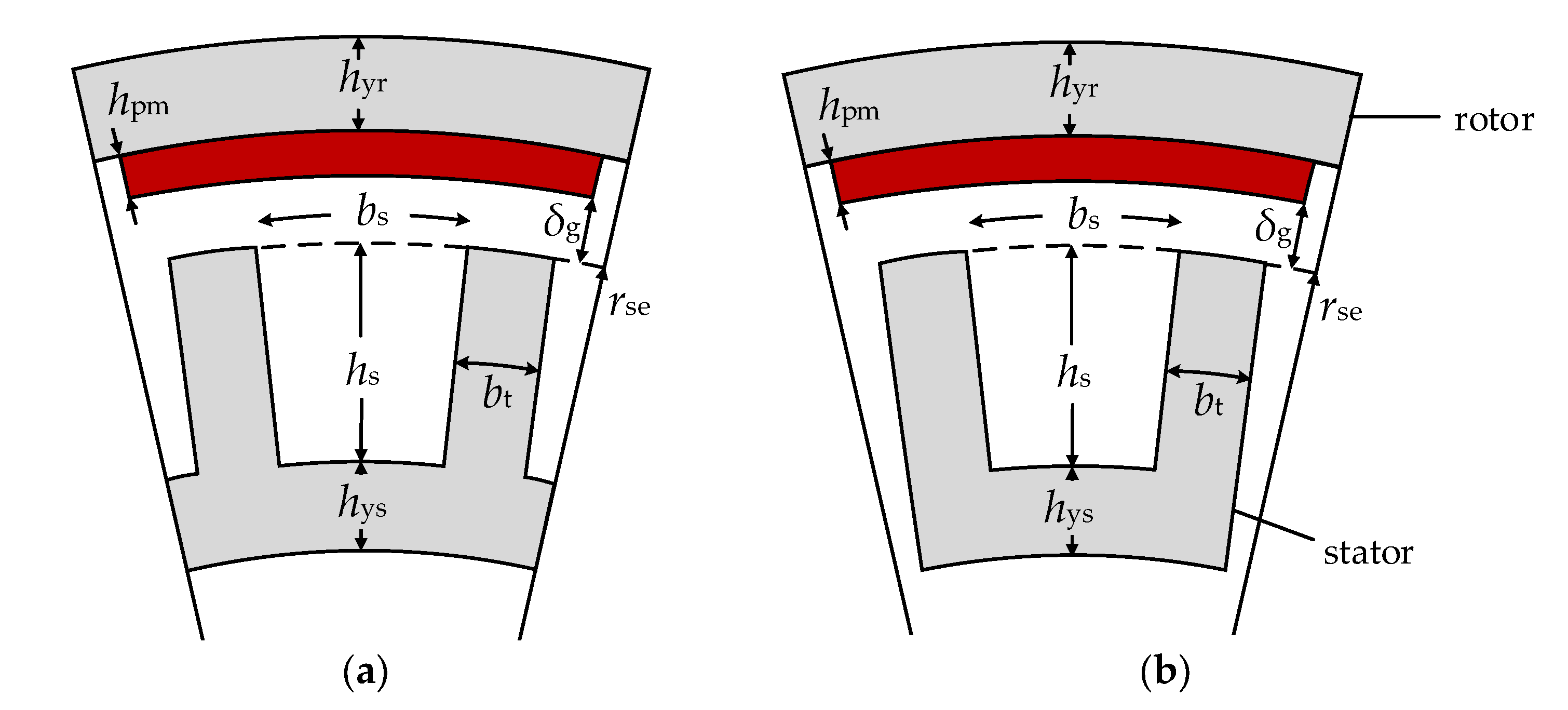
Schematics of selected PMSMs: (a) conventional PMSM with non-segmented stator, (b) PMSM with modular stator core.
Figure 2.
Schematics of selected PMSMs: (a) conventional PMSM with non-segmented stator, (b) PMSM with modular stator core.
Figure 3.
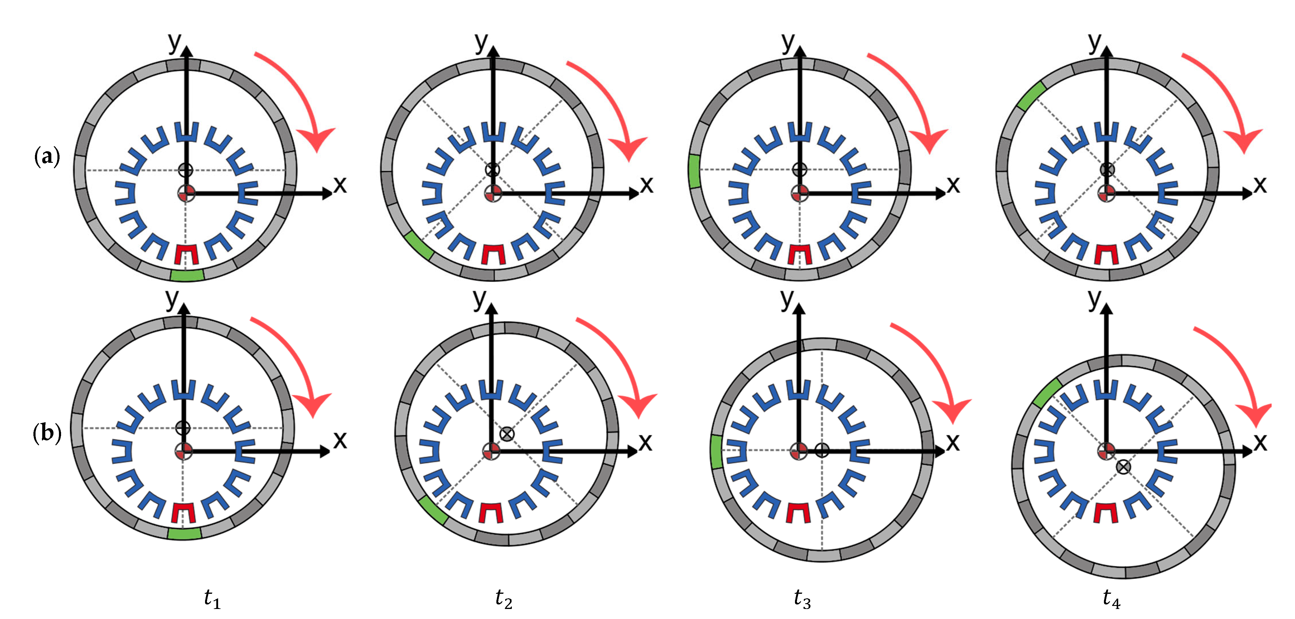
Representation of eccentricity types depending on its dynamics: (a) SE, in which the position of the minimum airgap is fixed, (b) DE, in which the position of the minimum airgap changes as the rotor structure rotates. Four arbitrary time instants are represented in the figure.
Figure 3.
Representation of eccentricity types depending on its dynamics: (a) SE, in which the position of the minimum airgap is fixed, (b) DE, in which the position of the minimum airgap changes as the rotor structure rotates. Four arbitrary time instants are represented in the figure.
Figure 4.
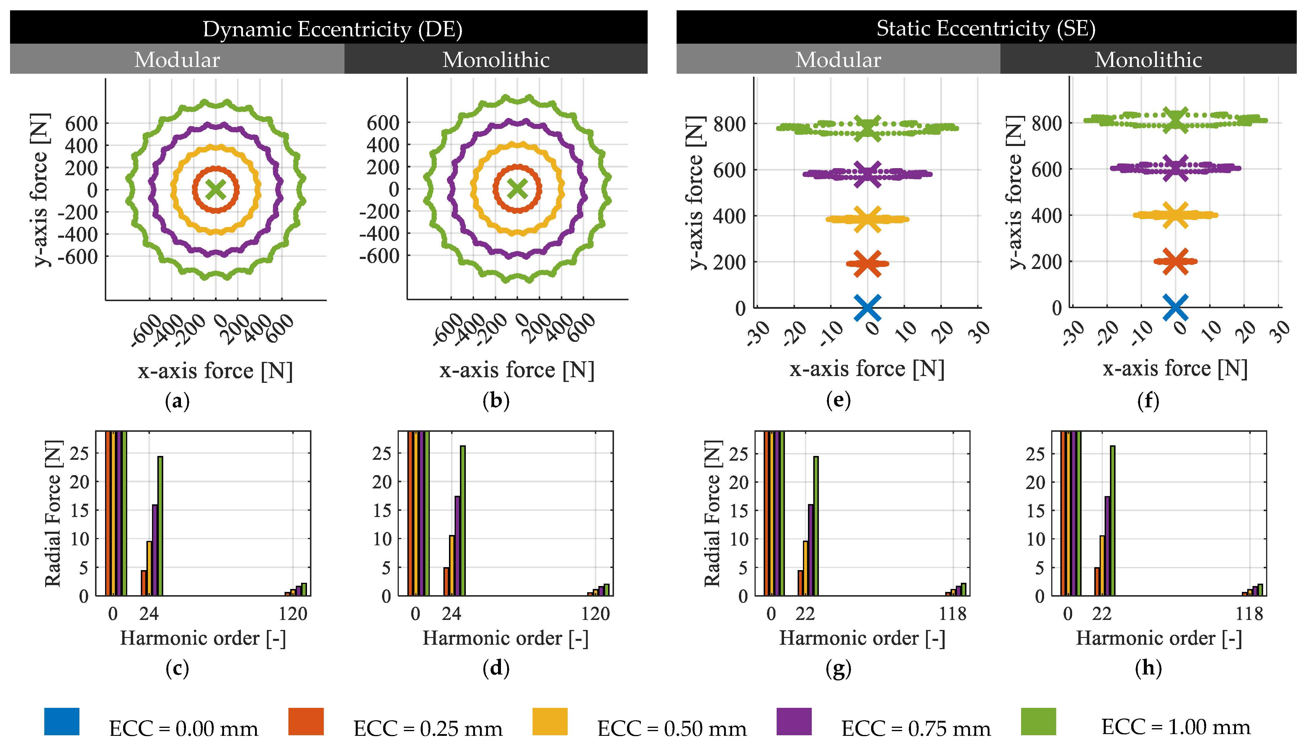
FE evaluation of radial forces acting on the rotor structure in the presence of DE (left column) and SE (right column) for a 24-slot, 22-pole PMSM and MPMSM: (a) x-axis and y-axis forces of DE on MPMSM, (b) x-axis and y-axis forces of DE on PMSM, (c) radial force spatial harmonic content of DE on MPMSM, (d) radial force spatial harmonic content of DE on PMSM, (e) x-axis and y-axis forces of SE on MPMSM, (f) x-axis and y-axis forces of SE on PMSM, (g) radial force spatial harmonic content of SE on MPMSM, (h) radial force spatial harmonic content of SE on PMSM.
Figure 4.
FE evaluation of radial forces acting on the rotor structure in the presence of DE (left column) and SE (right column) for a 24-slot, 22-pole PMSM and MPMSM: (a) x-axis and y-axis forces of DE on MPMSM, (b) x-axis and y-axis forces of DE on PMSM, (c) radial force spatial harmonic content of DE on MPMSM, (d) radial force spatial harmonic content of DE on PMSM, (e) x-axis and y-axis forces of SE on MPMSM, (f) x-axis and y-axis forces of SE on PMSM, (g) radial force spatial harmonic content of SE on MPMSM, (h) radial force spatial harmonic content of SE on PMSM.
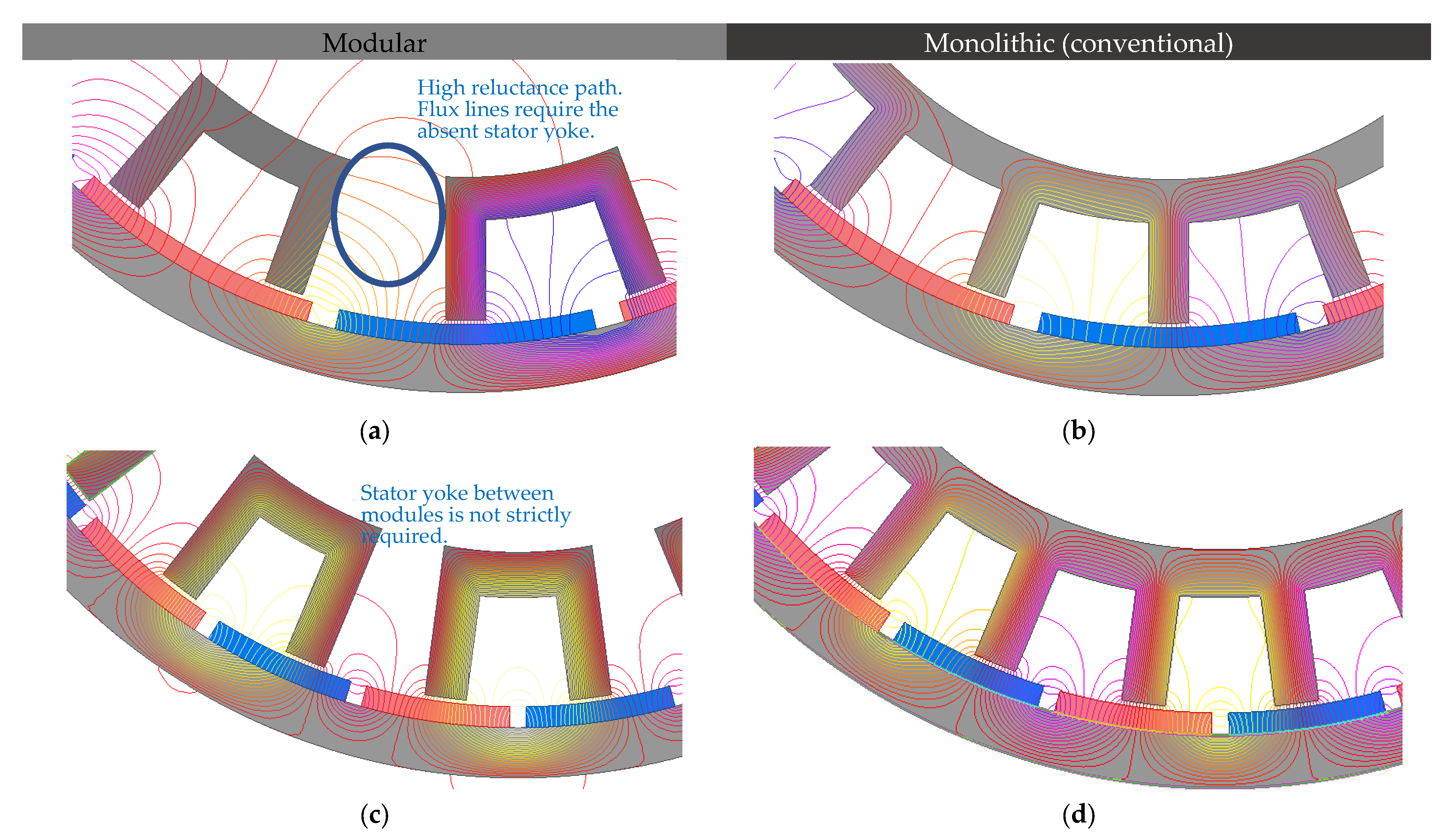
Figure 5.
Close-up to flux density lines for different values of q: (a) Modular 18-slot, 12-pole, , (b) monolithic, 18-slot, 12-pole, , (c) modular, 24-slot, 22-pole, (d) monolithic, 24-slot, 22-pole, .
Figure 5.
Close-up to flux density lines for different values of q: (a) Modular 18-slot, 12-pole, , (b) monolithic, 18-slot, 12-pole, , (c) modular, 24-slot, 22-pole, (d) monolithic, 24-slot, 22-pole, .
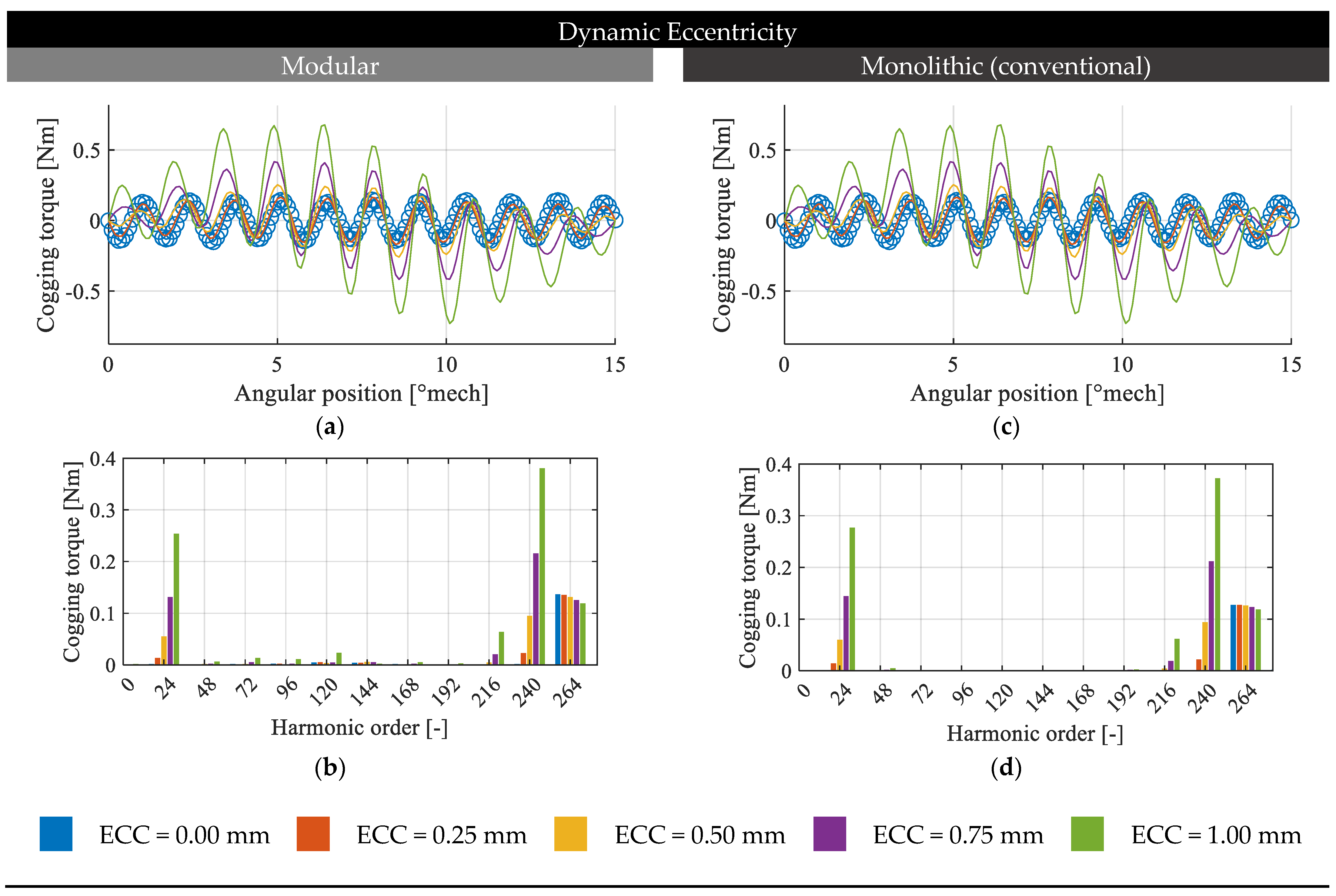
Figure 6.
FE evaluation of cogging torque in the presence of DE for the 24-slot, 22-pole PMSM and MPMSM: (a) cogging torque waveform for the modular machine, (b) cogging torque spectrum for the modular machine, (c) cogging torque waveform for the monolithic machine, (d) cogging torque spectrum for the monolithic machine.
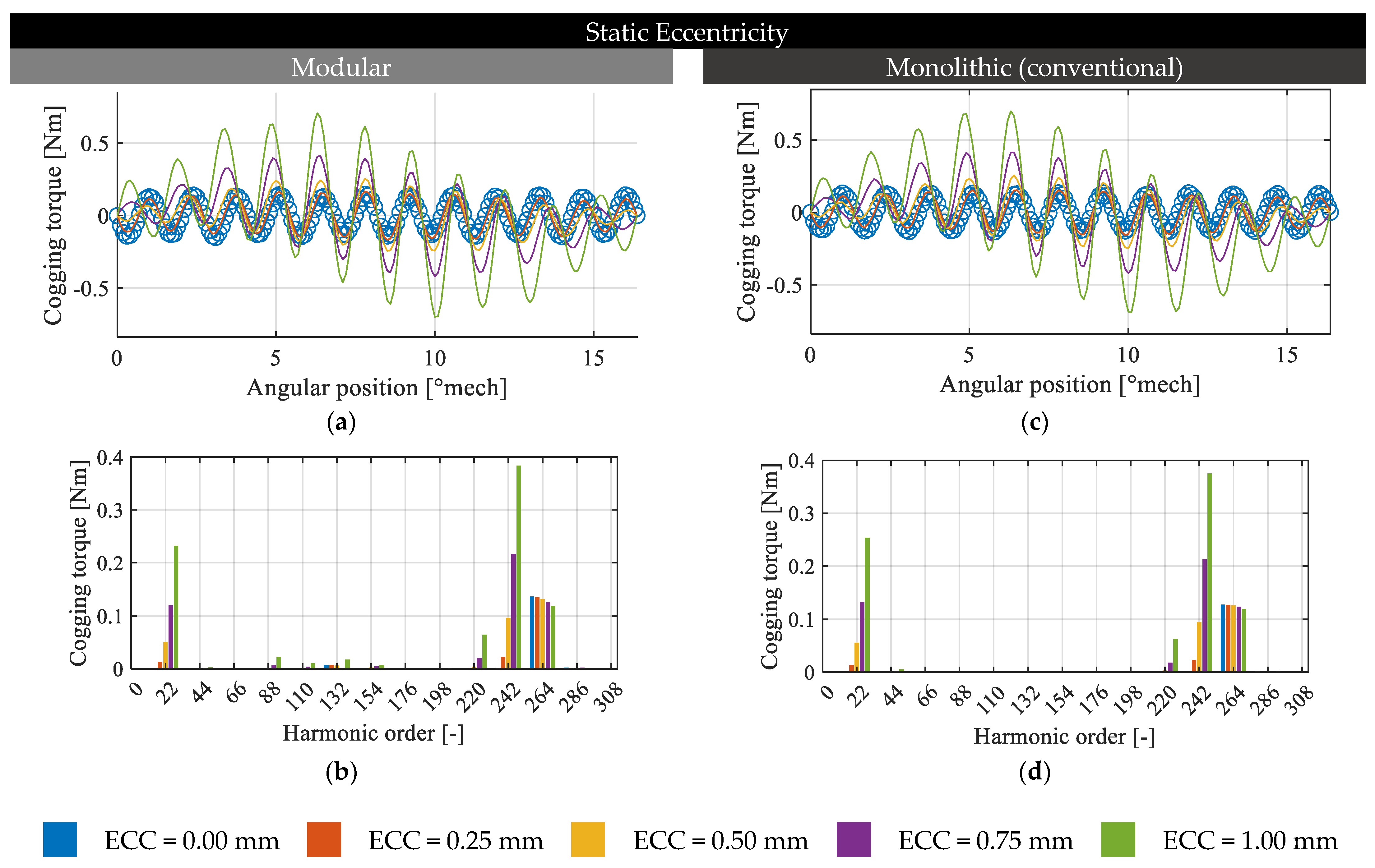
Figure 7.
FE evaluation of cogging torque in the presence of SE for 24-slot, 22-pole PMSM and MPMSM: (a) cogging torque waveform for the modular machine, (b) cogging torque spectrum for the modular machine, (c) cogging torque waveform for the monolithic machine, (d) cogging torque spectrum for the monolithic machine.
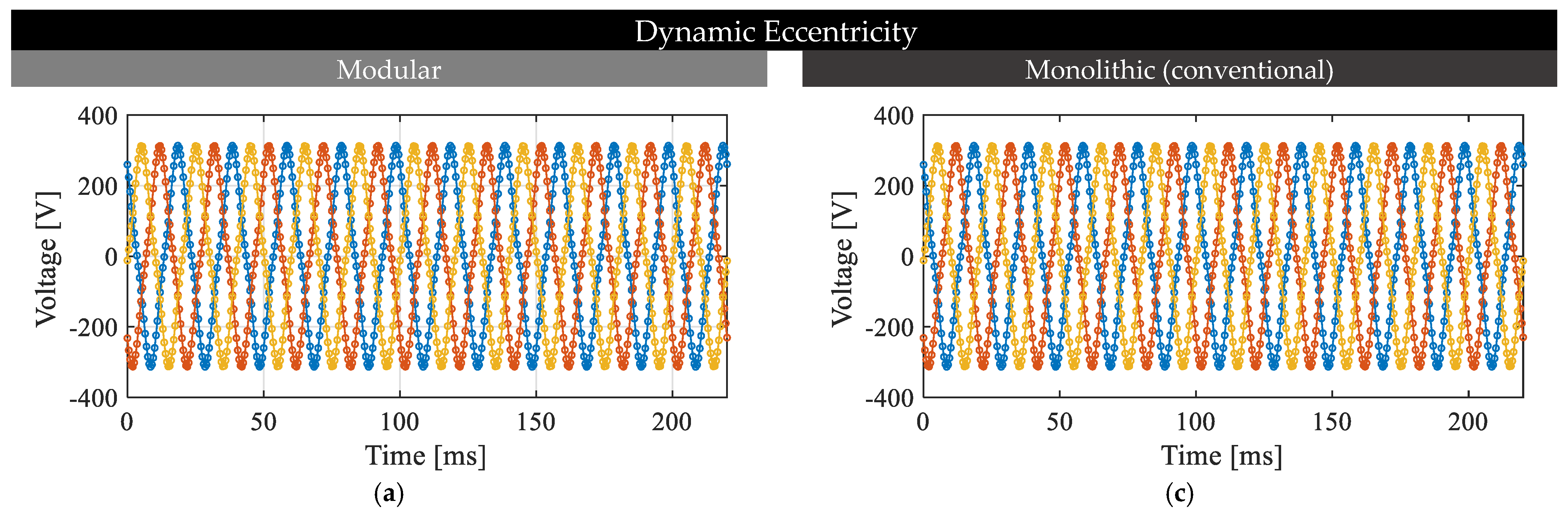
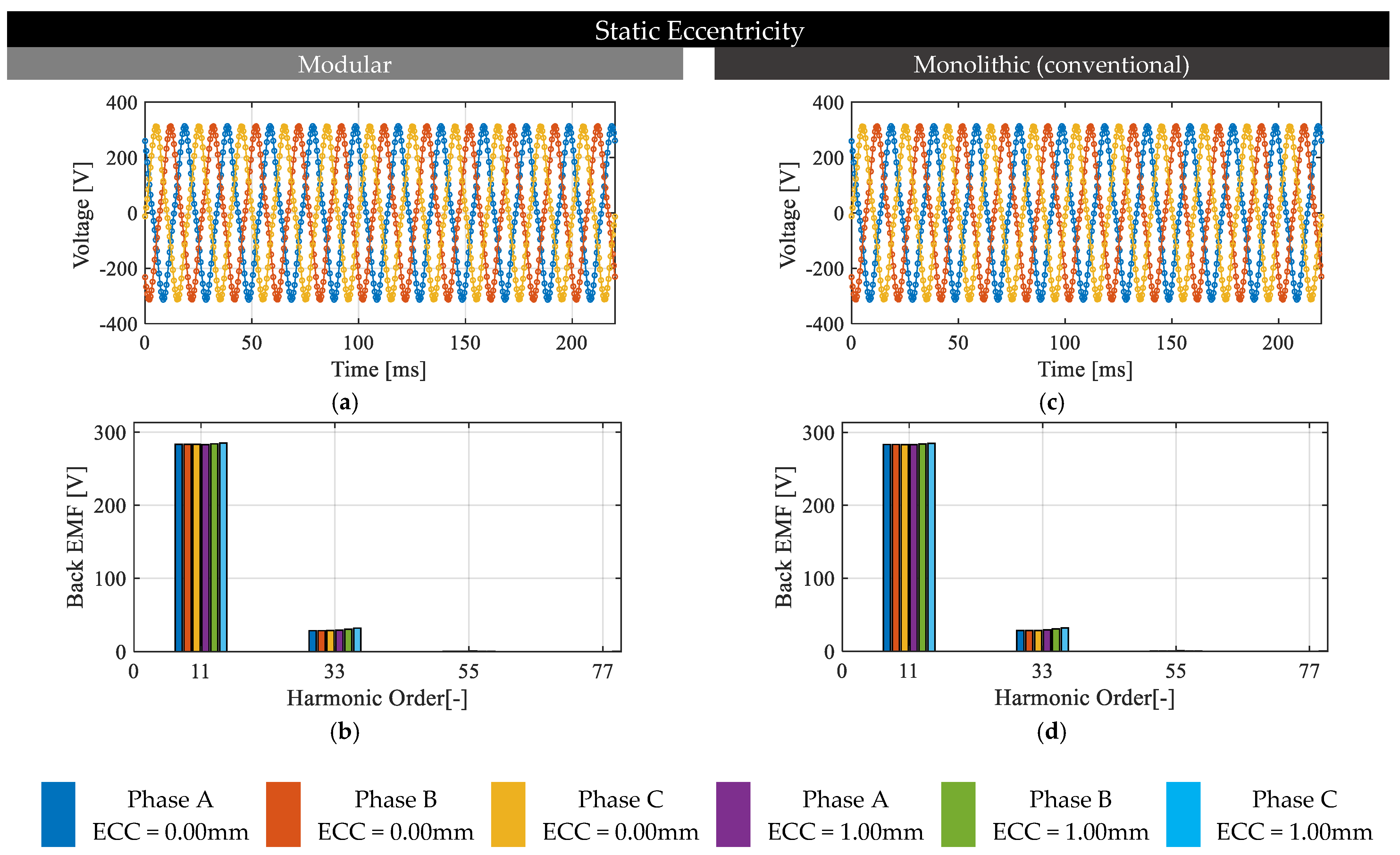
Figure 8.
FE evaluation of the back-emf in the presence of DE for a 24-slot, 22-pole PMSM and MPMSM: (a) back-emf waveform for the modular machine, (b) back-emf spectrum for the modular machine, (c) back-emf waveform for the monolithic machine, (d) back-emf spectrum for the monolithic machine.
Figure 8.
FE evaluation of the back-emf in the presence of DE for a 24-slot, 22-pole PMSM and MPMSM: (a) back-emf waveform for the modular machine, (b) back-emf spectrum for the modular machine, (c) back-emf waveform for the monolithic machine, (d) back-emf spectrum for the monolithic machine.
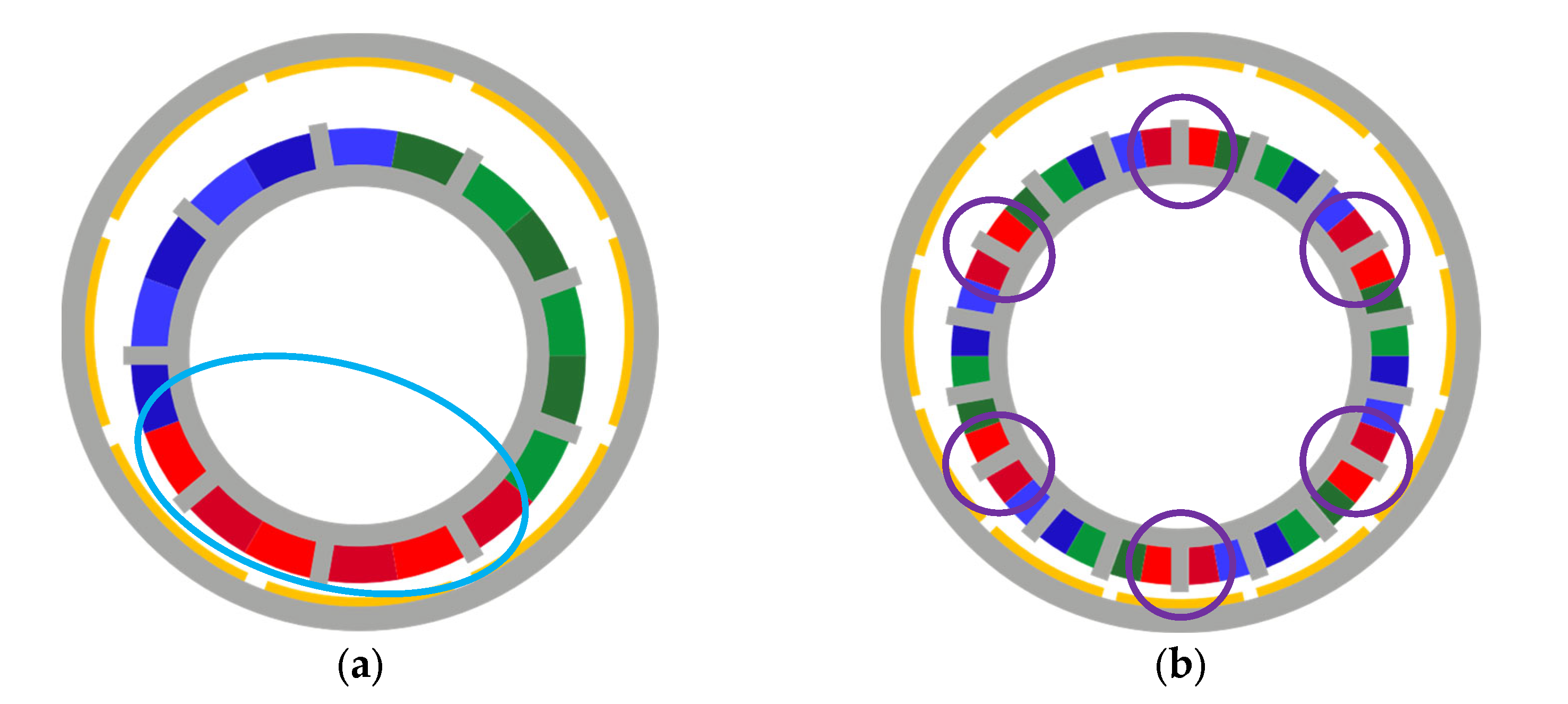
Figure 9.
Schematics of (a) a 9-slot, 8-pole PMSM with conventional stator core subject to eccentricity. In this case, the phase windings form a single group of conductors (light blue oval) distributed in a specific part of the stator circumference and (b) an 18-slot, 12-pole PMSM with conventional stator core subject to eccentricity. In this case, the phase windings form six group of conductors (light blue oval) evenly distributed in the stator circumference, damping the potential back-emf unbalance.
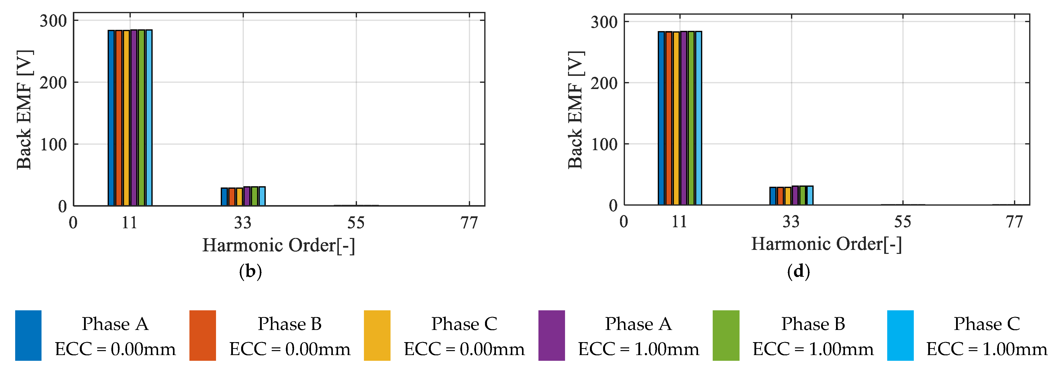
Figure 10.
FE evaluation of the back-emf in the presence of SE for a 24-slot, 22-pole PMSM and MPMSM: (a) back-emf waveform for the modular machine, (b) back-emf spectrum for the modular machine, (c) back-emf waveform for the monolithic machine, (d) back-emf spectrum for the monolithic machine.
Figure 10.
FE evaluation of the back-emf in the presence of SE for a 24-slot, 22-pole PMSM and MPMSM: (a) back-emf waveform for the modular machine, (b) back-emf spectrum for the modular machine, (c) back-emf waveform for the monolithic machine, (d) back-emf spectrum for the monolithic machine.
Table 1.
Main data of the machines (MPMSM and PMSM).
Table 1.
Main data of the machines (MPMSM and PMSM).
| Symbol | Quantity | Value |
|---|
| Effective core length | 70.0 mm |
| Stator outer radius | 133.0 mm |
| Airgap length | 2.0 mm |
| Slot width | 24.8 mm * |
| Slot height | 27.5 mm |
| Tooth width | 10.0 mm * |
| Height of the stator yoke | 10.5 mm |
| Height of the rotor yoke | 10.0 mm |
| PM height | 5.0 mm |
| PM remanence | 1.1 T |
| Relative recoil permeability | 1.04 |
Table 2.
Selected slot/pole combinations, including their winding layout considering TCW.
Table 2.
Selected slot/pole combinations, including their winding layout considering TCW.
| Slot Number | Pole Number | q | | Winding Layout |
|---|
| 18 | 12 | ½ | 6 | …|A A′|B B′|C C′|… |
| 18 | 20 | 3/10 | 2 | …|C′ A|A′ A′|A A|A′ B|B′ B′|B B|B′ C|C′ C′|C C|… |
| 24 | 20 | 2/5 | 4 | …|C′ A|A′ A’|A B′|B B|B′ C|C′ C′|C A′|A A|A′ B| B′ B′|B C′|C C|… |
| 24 | 22 | 4/11 | 2 | ![Applsci 13 02777 i001]() |
| 24 | 28 | 2/7 | 4 | …|C′ A|A′ A′|A B′|B B|B′ C|C′ C′|C A′|A A|A′ B| B′ B′|B C′|C C|… |
Table 3.
Eccentricity magnitudes analyzed in the selected PMSMs.
Table 3.
Eccentricity magnitudes analyzed in the selected PMSMs.
Eccentricity Magnitude
(% of Nominal Airgap Length) | Eccentricity Magnitude
(mm) | Severity |
|---|
| 12.5 | 0.25 | Very low |
| 25.0 | 0.50 | Low |
| 37.5 | 0.75 | Medium |
| 50.0 | 1.00 | High |
Table 4.
Average UMF of different PMSM and MPMSM slot/pole combinations in the presence of DE.
Table 4.
Average UMF of different PMSM and MPMSM slot/pole combinations in the presence of DE.
| | ECC | 0 mm (Faultless) | 0.25 mm | 0.50 mm | 0.75 mm | 1.00 mm |
|---|
| Q/2p | |
|---|
| | Mod [N] | Mon [N] | Mod [N] | Mon [N] | Mod [N] | Mon [N] | Mod [N] | Mon [N] | Mod [N] | Mon [N] |
| 18S 12P | 0 | 0 | 92 | 116 | 184 | 231 | 277 | 348 | 370 | 466 |
| 18S 20P | 0 | 0 | 148 | 151 | 296 | 304 | 446 | 458 | 599 | 614 |
| 24S 20P | 0 | 0 | 181 | 194 | 362 | 390 | 546 | 588 | 733 | 790 |
| 24S 22P | 0 | 0 | 192 | 200 | 385 | 401 | 580 | 604 | 780 | 813 |
| 24S 28P | 0 | 0 | 203 | 209 | 408 | 419 | 617 | 634 | 833 | 856 |
Table 5.
Difference between the radial force on modular and monolithic machines in terms of the number of slots per pole per phase.
Table 5.
Difference between the radial force on modular and monolithic machines in terms of the number of slots per pole per phase.
| Q/2p | q | | | |
|---|
| 18S 12P | 1/2 | 370 | 466 | 25.9% |
| 18S 20P | 3/10 | 599 | 614 | 2.5% |
| 24S 20P | 2/5 | 733 | 790 | 7.8% |
| 24S 22P | 4/11 | 780 | 813 | 4.2% |
| 24S 28P | 2/7 | 833 | 856 | 2.7% |
Table 6.
Radial force ripple for different slot/pole combinations of PMSM and MPMSM in the presence of DE.
Table 6.
Radial force ripple for different slot/pole combinations of PMSM and MPMSM in the presence of DE.
| | ECC | 0 mm (Faultless) | 0.25 mm | 0.50 mm | 0.75 mm | 1.00 mm | Main HO |
|---|
| Q/2p | |
|---|
| | Mod [N] | Mon [N] | Mod [N] | Mon [N] | Mod [N] | Mon [N] | Mod [N] | Mon [N] | Mod [N] | Mon [N] | Mod [-] | Mon [-] |
| 18S 12P | 0 | 0 | 4 | 2 | 12 | 4 | 23 | 7 | 38 | 9 | 18 | 18 |
| 18S 20P | 0 | 0 | 81 | 83 | 160 | 164 | 235 | 242 | 304 | 314 | 18 | 18 |
| 24S 20P | 0 | 0 | 3 | 1 | 6 | 3 | 10 | 7 | 22 | 13 | 24 | 24 |
| 24S 22P | 0 | 0 | 10 | 11 | 22 | 24 | 37 | 39 | 55 | 58 | 24 | 24 |
| 24S 28P | 0 | 0 | 1 | 1 | 2 | 1 | 3 | 3 | 7 | 5 | 24 | 24 |
Table 7.
Average UMF for different slot/pole combinations of PMSM and MPMSM in the presence of SE.
Table 7.
Average UMF for different slot/pole combinations of PMSM and MPMSM in the presence of SE.
| | ECC | q | 0 mm (Faultless) | 0.25 mm | 0.50 mm | 0.75 mm | 1.00 mm |
|---|
| |
|---|
| | | Mod [N] | Mon [N] | Mod [N] | Mon [N] | Mod [N] | Mon [N] | Mod [N] | Mon [N] | Mod [N] | Mon [N] |
| 18S 12P | 1/2 | 0 | 0 | 92 | 115 | 183 | 231 | 276 | 348 | 370 | 466 |
| 18S 20P | 3/10 | 0 | 0 | 148 | 151 | 296 | 303 | 446 | 457 | 599 | 614 |
| 24S 20P | 2/5 | 0 | 0 | 180 | 194 | 362 | 389 | 546 | 587 | 733 | 790 |
| 24S 22P | 4/11 | 0 | 0 | 192 | 200 | 384 | 400 | 580 | 604 | 779 | 812 |
| 24S 28P | 2/7 | 0 | 0 | 203 | 208 | 408 | 419 | 617 | 634 | 833 | 855 |
Table 8.
Radial force ripple for different slot/pole combinations of PMSM and MPMSM in the presence of SE.
Table 8.
Radial force ripple for different slot/pole combinations of PMSM and MPMSM in the presence of SE.
| | ECC | 0 mm (Faultless) | 0.25 mm | 0.50 mm | 0.75 mm | 1.00 mm | Main HO |
|---|
| |
|---|
| | Mod [N] | Mon [N] | Mod [N] | Mon [N] | Mod [N] | Mon [N] | Mod [N] | Mon [N] | Mod [N] | Mon [N] | Mod [-] | Mon [-] |
| 18S 12P | 0 | 0 | 4 | 2 | 12 | 4 | 23 | 6 | 36 | 8 | 12 | 12 |
| 18S 20P | 0 | 0 | 81 | 83 | 160 | 165 | 236 | 244 | 307 | 318 | 20 | 20 |
| 24S 20P | 0 | 0 | 2 | 1 | 5 | 3 | 10 | 6 | 20 | 12 | 20 | 20 |
| 24S 22P | 0 | 0 | 11 | 12 | 22 | 24 | 37 | 40 | 55 | 60 | 22 | 22 |
| 24S 28P | 0 | 0 | 1 | 0 | 2 | 1 | 3 | 2 | 7 | 5 | 28 | 28 |
Table 9.
Cogging torque NHC of different PMSM and MPMSM-slot/pole combinations in the presence of DE.
Table 9.
Cogging torque NHC of different PMSM and MPMSM-slot/pole combinations in the presence of DE.
| | ECC | HONHC | 0 mm (Faultless) | 0.25 mm | 0.50 mm | 0.75 mm | 1.00 mm |
|---|
| |
|---|
| | | Mod [Nm] | Mon [Nm] | Mod [Nm] | Mon [Nm] | Mod [Nm] | Mon [Nm] | Mod [Nm] | Mon [Nm] | Mod [Nm] | Mon [Nm] |
| 18S 12P | 72 | 19.11 | 22.42 | 19.13 | 22.44 | 19.17 | 22.46 | 19.24 | 22.49 | 19.34 | 22.54 |
| 18S 20P | 180 | 0.63 | 0.66 | 0.62 | 0.65 | 0.59 | 0.62 | 0.54 | 0.56 | 0.47 | 0.48 |
| 24S 20P | 120 | 3.92 | 2.70 | 3.91 | 2.71 | 3.88 | 2.77 | 3.84 | 2.86 | 3.83 | 2.99 |
| 24S 22P | 264 | 0.27 | 0.25 | 0.27 | 0.25 | 0.26 | 0.25 | 0.25 | 0.25 | 0.24 | 0.24 |
| 24S 28P | 168 | 2.28 | 0.72 | 2.28 | 0.73 | 2.30 | 0.74 | 2.34 | 0.77 | 2.40 | 0.81 |
Table 10.
Peak-to-peak value of cogging torque AHC of different PMSM and MPMSM slot/pole combinations in the presence of DE.
Table 10.
Peak-to-peak value of cogging torque AHC of different PMSM and MPMSM slot/pole combinations in the presence of DE.
| | ECC | | | 0.25 mm | 0.50 mm | 0.75 mm | 1.00 mm |
|---|
| |
|---|
| | | | Mod [Nm] | Mon [Nm] | Mod [Nm] | Mon [Nm] | Mod [Nm] | Mon [Nm] | Mod [Nm] | Mon [Nm] |
|---|
| 18S 12P | 72 | 6 | 0.06 | 0.06 | 0.12 | 0.15 | 0.26 | 0.29 | 0.45 | 0.48 |
| 18S 20P | 180 | 2 | 0.20 | 0.20 | 0.74 | 0.78 | 1.59 | 1.70 | 2.80 | 2.95 |
| 24S 20P | 120 | 4 | 0.04 | 0.06 | 0.13 | 0.09 | 0.32 | 0.22 | 0.63 | 0.50 |
| 24S 22P | 264 | 2 | 0.08 | 0.09 | 0.30 | 0.31 | 0.72 | 0.73 | 1.39 | 1.36 |
| 24S 28P | 168 | 4 | 0.02 | 0.02 | 0.05 | 0.04 | 0.13 | 0.09 | 0.29 | 0.21 |
Table 11.
Relative cogging torque increase of different PMSM and MPMSM slot/pole combinations in the presence of DE.
Table 11.
Relative cogging torque increase of different PMSM and MPMSM slot/pole combinations in the presence of DE.
| | ECC | | 0.25 mm | 0.50 mm | 0.75 mm | 1.00 mm |
|---|
| |
|---|
| | | Mod [%] | Mon [%] | Mod [%] | Mon [%] | Mod [%] | Mon [%] | Mod [%] | Mon [%] |
| 18S 12P | 6 | 0.19 | 0.22 | 0.53 | 0.65 | 1.15 | 1.30 | 2.07 | 2.18 |
| 18S 20P | 2 | 27.23 | 26.21 | 102.72 | 105.80 | 238.69 | 236.47 | 422.04 | 424.21 |
| 24S 20P | 4 | 0.29 | 0.69 | 1.33 | 3.05 | 4.42 | 7.62 | 11.00 | 17.45 |
| 24S 22P | 2 | 12.58 | 16.57 | 72.73 | 89.18 | 180.61 | 215.49 | 374.00 | 435.19 |
| 24S 28P | 4 | 0.41 | 0.11 | 1.62 | 2.12 | 4.64 | 8.61 | 10.33 | 26.39 |
Table 12.
Cogging torque NHC of different PMSM and MPMSM slot/pole combinations in the presence of SE.
Table 12.
Cogging torque NHC of different PMSM and MPMSM slot/pole combinations in the presence of SE.
| | ECC | | 0 mm (Faultless) | 0.25 mm | 0.50 mm | 0.75 mm | 1.00 mm |
|---|
| |
|---|
| | | Mod [Nm] | Mon [Nm] | Mod [Nm] | Mon [Nm] | Mod [Nm] | Mon [Nm] | Mod [Nm] | Mon [Nm] | Mod [Nm] | Mon [Nm] |
| 18S 12P | 72 | 19.10 | 22.42 | 19.13 | 22.44 | 19.16 | 22.46 | 19.20 | 22.49 | 19.24 | 22.54 |
| 18S 20P | 180 | 0.63 | 0.66 | 0.62 | 0.66 | 0.60 | 0.63 | 0.57 | 0.59 | 0.52 | 0.54 |
| 24S 20P | 120 | 3.90 | 2.66 | 3.90 | 2.68 | 3.87 | 2.74 | 3.83 | 2.82 | 3.82 | 2.96 |
| 24S 22P | 264 | 0.27 | 0.25 | 0.27 | 0.25 | 0.26 | 0.25 | 0.25 | 0.25 | 0.24 | 0.24 |
| 24S 28P | 168 | 2.28 | 0.72 | 2.28 | 0.73 | 2.30 | 0.75 | 2.34 | 0.78 | 2.40 | 0.81 |
Table 13.
Relative cogging torque increase of different PMSM and MPMSM slot/pole combinations in the presence of SE.
Table 13.
Relative cogging torque increase of different PMSM and MPMSM slot/pole combinations in the presence of SE.
| | ECC | | | 0.25 mm | 0.50 mm | 0.75 mm | 1.00 mm |
|---|
| |
|---|
| | | | Mod [%] | Mon [%] | Mod [%] | Mon [%] | Mod [%] | Mon [%] | Mod [%] | Mon [%] |
| 18S 12P | 72 | 6 | 0.19 | 0.22 | 0.54 | 0.66 | 1.17 | 1.31 | 2.05 | 2.19 |
| 18S 20P | 180 | 2 | 28.92 | 24.87 | 117.38 | 107.98 | 260.77 | 244.69 | 462.91 | 439.94 |
| 24S 20P | 120 | 4 | 0.41 | 0.83 | 1.52 | 2.89 | 4.63 | 7.72 | 11.22 | 17.86 |
| 24S 22P | 264 | 2 | 12.31 | 16.10 | 67.51 | 87.25 | 178.98 | 210.45 | 373.15 | 417.45 |
| 24S 28P | 168 | 4 | 0.55 | 0.59 | 1.46 | 2.72 | 4.37 | 9.48 | 10.14 | 25.80 |
Table 14.
Fundamental component and third-order harmonic of back-emf for different PMSM and MPMSM slot/pole combinations in the presence of DE.
Table 14.
Fundamental component and third-order harmonic of back-emf for different PMSM and MPMSM slot/pole combinations in the presence of DE.
| | ECC | | 0 mm (Faultless) | 1.00 mm |
|---|
| |
|---|
| | | Modular [V] | Monolithic [V] | Modular [V] | Monolithic [V] |
| | HO | A | B | C | A | B | C | A | B | C | A | B | C |
| 18S 12P | 1st | 247.5 | 247.5 | 247.5 | 263.7 | 263.8 | 263.7 | 247.6 | 247.7 | 247.6 | 263.7 | 263.9 | 263.7 |
| 3rd | 21.9 | 21.9 | 21.9 | 24.6 | 24.0 | 24.6 | 22.0 | 22.0 | 22.0 | 24.8 | 24.4 | 24.9 |
| 18S 20P | 1st | 281.0 | 281.1 | 281.0 | 275.4 | 275.5 | 275.4 | 281.7 | 281.7 | 281.6 | 276.2 | 276.2 | 276.2 |
| 3rd | 31.6 | 31.6 | 31.6 | 35.9 | 36.0 | 36.0 | 33.3 | 33.3 | 33.3 | 37.8 | 37.8 | 37.8 |
| 24S 20P | 1st | 276.7 | 276.7 | 276.6 | 275.9 | 275.9 | 275.8 | 277.5 | 277.5 | 277.5 | 276.7 | 276.6 | 276.6 |
| 3rd | 37.9 | 37.9 | 37.9 | 37.8 | 37.8 | 37.9 | 40.5 | 40.6 | 40.6 | 39.7 | 39.7 | 39.7 |
| 24S 22P | 1st | 283.4 | 283.4 | 283.3 | 283.2 | 283.2 | 283.2 | 284.1 | 284.1 | 284.1 | 283.9 | 283.9 | 283.9 |
| 3rd | 28.7 | 28.7 | 28.7 | 29.0 | 28.9 | 29.0 | 30.7 | 30.7 | 30.7 | 30.8 | 30.8 | 30.9 |
| 24S 28P | 1st | 300.9 | 300.9 | 300.9 | 292.5 | 292.5 | 292.5 | 303.4 | 303.4 | 303.4 | 294.8 | 294.8 | 294.8 |
| 3rd | 9.5 | 9.5 | 9.7 | 18.9 | 18.9 | 19.1 | 9.6 | 9.6 | 9.8 | 19.8 | 19.8 | 19.8 |
Table 15.
Maximum back-emf unbalance for different PMSM and MPMSM slot/pole combinations in the presence of DE.
Table 15.
Maximum back-emf unbalance for different PMSM and MPMSM slot/pole combinations in the presence of DE.
| ECC | Modular [V] | Monolithic [V] | |
|---|
| 18S 12P | 0.526 | 0.657 | 6 |
| 18S 20P | 10.386 | 9.091 | 2 |
| 24S 20P | 1.331 | 1.312 | 4 |
| 24S 22P | 6.660 | 6.286 | 2 |
| 24S 28P | 1.065 | 1.301 | 4 |
Table 16.
Fundamental component and third-order harmonic of back-emf for different PMSM and MPMSM slot/pole combinations in the presence of SE.
Table 16.
Fundamental component and third-order harmonic of back-emf for different PMSM and MPMSM slot/pole combinations in the presence of SE.
| | ECC | | 0 mm (Faultless) | 1.00 mm |
|---|
| |
|---|
| | | Modular [V] | Monolithic [V] | Modular [V] | Monolithic [V] |
| | HO | A | B | C | A | B | C | A | B | C | A | B | C |
| 18S 12P | 1st | 247.2 | 247.3 | 247.2 | 263.5 | 263.7 | 263.5 | 247.5 | 247.6 | 247.4 | 263.7 | 263.8 | 263.7 |
| 3rd | 21.9 | 21.9 | 21.9 | 24.5 | 24.1 | 24.5 | 21.9 | 22.0 | 22.1 | 24.6 | 24.6 | 24.6 |
| 18S 20P | 1st | 280.7 | 280.8 | 280.7 | 275.1 | 275.2 | 275.1 | 281.2 | 280.6 | 283.0 | 275.3 | 275.4 | 277.5 |
| 3rd | 31.7 | 31.7 | 31.7 | 36.0 | 36.1 | 36.1 | 30.5 | 32.9 | 36.97 | 36.2 | 36.2 | 41.3 |
| 24S 20P | 1st | 276.7 | 276.8 | 276.7 | 281.7 | 281.7 | 281.7 | 277.4 | 277.4 | 277.3 | 282.3 | 282.3 | 282.2 |
| 3rd | 37.9 | 37.8 | 37.9 | 38.6 | 38.6 | 38.6 | 40.3 | 40.4 | 40.4 | 40.4 | 40.4 | 40.5 |
| 24S 22P | 1st | 283.4 | 283.4 | 283.3 | 283.2 | 283.2 | 283.2 | 283.1 | 284.0 | 285.0 | 282.9 | 283.9 | 284.9 |
| 3rd | 28.7 | 28.7 | 28.7 | 29.0 | 29.0 | 29.0 | 29.3 | 30.8 | 32.2 | 29.6 | 31.0 | 32.2 |
| 24S 28P | 1st | 300.9 | 301.0 | 300.9 | 292.5 | 292.5 | 292.5 | 303.2 | 303.2 | 303.1 | 294.6 | 294.6 | 294.5 |
| 3rd | 9.5 | 9.5 | 9.6 | 19.0 | 19.0 | 19.1 | 9.7 | 9.7 | 9.7 | 19.8 | 19.8 | 19.8 |
Table 17.
Maximum back-emf unbalance for different PMSM and MPMSM slot/pole combinations in the presence of SE.
Table 17.
Maximum back-emf unbalance for different PMSM and MPMSM slot/pole combinations in the presence of SE.
| ECC | Modular [V] | Monolithic [V] | |
|---|
| 18S 12P | 0.453 | 0.527 | 6 |
| 18S 20P | 7.134 | 7.284 | 2 |
| 24S 20P | 0.391 | 0.367 | 4 |
| 24S 22P | 4.012 | 3.934 | 2 |
| 24S 28P | 0.397 | 0.539 | 4 |
Table 18.
Mean torque of different PMSM and MPMSM slot/pole combinations in the presence of DE.
Table 18.
Mean torque of different PMSM and MPMSM slot/pole combinations in the presence of DE.
| | ECC | 0 mm (Faultless) | 0.25 mm | 0.50 mm | 0.75 mm | 1.00 mm |
|---|
| |
|---|
| | Mod [Nm] | Mon [Nm] | Mod [Nm] | Mon [Nm] | Mod [Nm] | Mon [Nm] | Mod [Nm] | Mon [Nm] | Mod [Nm] | Mon [Nm] |
| 18S 12P | 147.8 | 171.8 | 148.0 | 172.0 | 147.8 | 171.8 | 147.9 | 171.8 | 148.0 | 171.9 |
| 18S 20P | 218.9 | 226.1 | 218.7 | 225.8 | 218.9 | 226.0 | 218.9 | 226.0 | 219.0 | 226.2 |
| 24S 20P | 208.4 | 215.4 | 207.6 | 214.6 | 207.6 | 214.6 | 208.1 | 215.1 | 208.3 | 215.3 |
| 24S 22P | 216.2 | 218.4 | 216.2 | 218.4 | 216.3 | 218.5 | 216.4 | 218.6 | 216.6 | 218.8 |
| 24S 28P | 207.4 | 232.4 | 207.2 | 232.2 | 207.4 | 232.4 | 207.8 | 232.7 | 208.5 | 233.4 |
Table 19.
Mean torque of different PMSM and MPMSM slot/pole combinations in the presence of SE.
Table 19.
Mean torque of different PMSM and MPMSM slot/pole combinations in the presence of SE.
| | ECC | 0 mm (Faultless) | 0.25 mm | 0.50 mm | 0.75 mm | 1.00 mm |
|---|
| |
|---|
| | Mod [Nm] | Mon [Nm] | Mod [Nm] | Mon [Nm] | Mod [Nm] | Mon [Nm] | Mod [Nm] | Mon [Nm] | Mod [Nm] | Mon [Nm] |
| 18S 12P | 147.7 | 171.7 | 147.7 | 171.8 | 147.7 | 171.7 | 147.7 | 171.8 | 147.8 | 171.8 |
| 18S 20P | 218.2 | 225.3 | 218.4 | 225.5 | 218.4 | 225.5 | 218.6 | 225.7 | 218.7 | 225.9 |
| 24S 20P | 207.9 | 214.9 | 208.0 | 215.0 | 208.0 | 215.0 | 208.3 | 215.3 | 208.4 | 215.3 |
| 24S 22P | 216.2 | 218.4 | 216.2 | 218.4 | 216.3 | 218.5 | 216.4 | 218.6 | 216.6 | 218.8 |
| 24S 28P | 207.3 | 232.2 | 207.2 | 232.2 | 207.4 | 232.4 | 207.8 | 232.7 | 208.1 | 232.9 |


 ,
, 


