Article

Differences in Properties between Hybrid Wire Arc Additive-Milling Subtractive Manufactured Aluminum and Magnesium Alloys

Wuhan National Laboratory for Optoelectronics (WNLO), Huazhong University of Science and Technology, Wuhan 430074, China
*
Author to whom correspondence should be addressed.
Appl. Sci. 2023, 13(4), 2720; https://doi.org/10.3390/app13042720
Submission received: 18 January 2023 / Revised: 13 February 2023 / Accepted: 17 February 2023 / Published: 20 February 2023
(This article belongs to the Special Issue Recent Trends on the Mechanical Properties of Additive Manufacturing)

Abstract

:
Hybrid wire arc additive-milling subtractive manufacturing (HWMM) is an effective way to improve the quality of complex metal components, but the difference in the properties of the aluminum alloy and magnesium alloy fabricated by HWMM has been not addressed. In the paper, the differences in deposition accuracy and tensile anisotropy between the Al5Si Al and AZ31B Mg alloys were studied by using the HWMM method. Under the optimal parameters, the minimum surface roughness of the AZ31B sample was 146.1 μm, which was 90% higher than for the Al5Si sample. The differences in the tensile strength and elongation of the AZ31B sample were 32% and 56%, respectively, being 6 and 3.3 times higher than those of the Al5Si samples. According to the fracture behavior of the samples, the tensile anisotropy of both alloys was mainly attributed to defects such as incomplete fusion and porosity in the fusion line. However, there was obvious structural inhomogeneity in AZ31B samples, where the grain size difference between adjacent areas reached 40%. This led to the easier fracture of AZ31B samples. These results contribute to our understanding of the HWMM of light alloys.

1. Introduction

With increasingly prominent global energy and environmental problems, the characteristics of being large scale, lightweight and integrated have gradually become the development trends of high-end equipment manufacturing, such as aerospace, shipbuilding, vehicles and nuclear power. Magnesium and aluminum alloys are widely used in aerospace, vehicles, electronics, satellites and other fields due to their low density, high specific strength, good electromagnetic shielding performance, good mechanical processing performance, good vibration and shock absorption and good dimensional stability [1,2,3]. The traditional casting–forging–milling process has the problems of low yield, low efficiency and a high cost in the small-batch and single-piece trial production of large-sized complex components. The hybrid additive and subtractive manufacturing process provides a new concept in solving the small-batch manufacturing and rapid development of large-sized complex components. Through the alternate processing of additive and subtractive materials, it can effectively solve the above processing problems and realize the integrated precision forming of complex components.
At present, aluminum alloy and magnesium alloy are prone to metallurgical defects in laser additive manufacturing due to their unique physical and chemical properties. Moreover, laser additive manufacturing has high laser radiation owing to the low energy absorption efficiency of aluminum alloy and magnesium alloy, which makes quality control difficult and leads to a low deposition rate, followed by high costs and low efficiency [4,5]. In addition, the fine powders of aluminum alloy and magnesium alloy, used for laser additive manufacturing, are not only difficult to prepare but also easily oxidized, resulting in combustion and even explosion. Therefore, laser additive manufacturing is not an efficient technique for large-scale aluminum alloy and magnesium alloy components, and increasing attention has been paid to wire arc additive manufacturing (WAAM). WAAM transfers heat to a wire and substrate through a high-conductivity plasma arc, which can result in a larger molten pool and slower solidification speed, and it helps gas and impurities to escape. It can effectively overcome the process problems in laser additive manufacturing and has the advantages of high material utilization, high deposition efficiency and excellent forming quality [6,7,8]. Therefore, WAAM is recognized as an effective production technique for large-size aluminum alloy and magnesium alloy components. However, WAAM is associated with rough surface quality, resulting in a large amount of secondary machining, because the heating area of the plasma arc column is large, and the energy is relatively dispersed. Therefore, it is possible to achieve technological breakthroughs by combining WAAM and milling, which provides a new and effective technical approach for small-batch, large-sized complex components of aluminum alloy and magnesium alloy.
Magnesium alloys have great application prospects in aerospace, automotives, communications and other fields, and they are referred to as green engineering materials in the new century, because of their advantages of low density, high specific strength, high specific stiffness and high damping [9,10,11]. Compared with aluminum alloy, magnesium alloy has much higher chemical activity and easier oxidation and flammability. In the laser additive manufacturing of magnesium alloy, due to the serious reflection of magnesium alloy to the laser and the low light absorption rate, the laser energy utilization rate and forming efficiency are low, and the magnesium powder is flammable and explosive; thus, it requires a strictly controlled working environment, resulting in a high cost for the laser additive manufacturing of magnesium alloy. At the same time, the WAAM of magnesium alloy can solve the problems of low forming efficiency and high costs, but magnesium alloy is prone to defects such as oxidation blackening, inclusions, cold shut and porosity in the process of WAAM [12], as well as low forming accuracy, poor surface quality and a small processing window. Takagi et al. conducted a study on the gas tungsten arc welding–wire arc additive manufacturing (GTAW–WAAM) of AZ31B magnesium alloy. It was found that the maximum tensile strength was 240 MPa, and the higher the welding speed, the smaller the grain size [13]. Guo et al. carried out research on the pulsed GTAW–WAAM of AZ31 magnesium alloy and found that the change in pulse frequency brought about the oscillation of the molten pool and a change in the cooling rate. When the pulse frequency was 12 Hz, the grain size was reduced to 21 μm, and the ultimate tensile strength (UTS) reached 263 MPa, but the geometric accuracy of the forming was poor [14]. Liu et al. studied the tensile anisotropy of AZ31B magnesium alloy fabricated by cold metal transfer–wire arc additive manufacturing (CMT–WAAM) and found that epitaxial columnar dendrites were formed along the deposition direction [15]. Shen et al. conducted a study on the swing welding process of AZ91 magnesium alloy by CMT–WAAM. It was found that the grain sizes above and below the fusion line were 13.9 μm and 33.2 μm, which were 69.7% and 25.2% lower than in the matrix, respectively [16]. Wang et al. conducted research on the WAAM of AZ31B magnesium alloy and found that coarse grains and pores were the main causes of tensile fracture, and the heat-affected zone softening effect existed in the sample microstructure [17]. Klein et al. studied the microstructure and mechanical properties of AZ61A magnesium alloy fabricated by WAAM. It was found that the anisotropy of tensile strength, yield strength and elongation was 3.0%, 5.2% and 0.7%, respectively. It was also found that the constitutional undercooling in the solidification front of the molten pool during deposition led to a fine grain structure [18]. Cen et al. carried out a study on the scanning laser-arc hybrid additive manufacturing of AZ31 magnesium alloy thin-walled components and found that the average grain size was reduced by 37.5% compared to that without scanning, and the ultimate tensile strength and elongation were 205 MPa and 20.7%, respectively [19]. Therefore, the study of magnesium alloy fabricated by hybrid wire arc additive-milling subtractive manufacturing (HWMM) can improve the stability and quality of magnesium alloys by removing oxide inclusions on the arc surface.
At present, research on hybrid additive and subtractive manufacturing focuses on the process planning of the forming process, mainly to improve the processing efficiency and processing accuracy and to reduce costs. Prado-Cerqueira et al. developed ER70S-6 low carbon steel semi-closed complex structural parts via cold metal transfer-hybrid wire arc additive–milling subtractive manufacturing (CMT–HWMM), and the side roughness Sa reached 18.7 μm [20,21]. Campatelli et al. conducted a study on hybrid wire arc additive-milling subtractive manufactured (HWMMed) S235JR structural steel blades and found that this process saves 60% and 34%, respectively, of material and energy compared with traditional milling [22]. Priarone et al. established an HWMM evaluation framework based on factors such as cost, manufacturing time, energy demand and carbon emissions, and carried out research on HWMM for ER70S-6 low-carbon steel complex frame structure parts, and they found that HWMM saves 50% and 57% of material and energy compared to traditional milling, respectively [23]. Xiong et al. carried out research on GH163 by plasma HWMM, which could control the size deviation of parts within ±0.05% and reduce the roughness Ra to 0.46 μm. However, the HWMM-produced parts still possessed tensile anisotropy, and the elongation along the forming direction (39.6%) was 90.4% higher than that in the vertical direction (20.8%) [24,25]. Afazov et al. carried out research on 316 L stainless steel nozzles by hybrid laser additive and subtractive manufacturing and found that the dimensional accuracy of the parts was controlled within 200 μm, and the surface roughness was controlled within 1 μm [26]. Wüst et al. carried out research on 1.2709 maraging steel parts produced by hybrid laser additive and subtractive manufacturing and established a surface roughness prediction model, and they found that the surface roughness Sa of the sample could be decreased to 0.835 μm [27]. Li et al. carried out research on 316L stainless steel via hybrid laser additive and subtractive manufacturing and found that milling increased its tensile strength by 16%, and the surface roughness Sa of the sample reached 1.9 μm [28]. Li et al. carried out research on the double-wire HWMM of an aluminum alloy stiffened panel and found that the surface roughness of the sample reached 1.38 μm, and the material utilization rate and processing efficiency were increased by 57% and 32%, respectively, compared with the traditional processing [29]. Xiao et al. carried out research on the gas metal arc welding–HWMM of 3 m grade cross-shaped aluminum alloy structural parts by using dual robot HWMM equipment, and the flatness of the upper surface of the formed parts was effectively controlled through local milling, while the forming accuracy was controlled within 3 mm [30]. However, so far, there is no literature report on the tensile property difference in HWMM-produced magnesium and aluminum alloy.
In this paper, the process of HWMM-produced AZ31B magnesium alloy was studied, and the difference in deposition accuracy between AZ31B magnesium alloy and Al5Si aluminum alloy was compared. The effect of milling on the tensile properties of HWMM-produced magnesium alloy was studied, and the difference in tensile strength and elongation anisotropy between AZ31B magnesium alloy and Al5Si aluminum alloy was discussed.

2. Materials and Methods

2.1. Materials and Equipment

The experimental equipment comprises two 6-DOF Fanuc industrial robots. The WAAM system is used in combination with a Fanuc M-710iC/50 and Fronius cold metal transfer (CMT) 4000 welder, and the milling system is used in combination with a larger load Fanuc R-2000iB/210F, motorized spindle, electrical cabinet, tool magazine, etc. The load and repeated positioning accuracy of the two robots are 50 kg, ±0.07 mm and 210 kg, ±0.3 mm, respectively. Details of the technology are summarized in Refs. [31,32].
The deposition material used was AZ31B magnesium alloy wire with a diameter of 1.6 mm and its chemical composition is shown in Table 1. The forming substrate was an AZ30 alloy sheet with a thickness of 5.2 mm. The protective gas used in the torch was 99.99% argon, and the gas flow rate was 25 L/min. Before the experiment, the polished substrate was fixed on the experimental platform and the surface was cleaned with acetone or alcohol.
Two CMT process and three deposition process combinations (pure CMT, pulse CMT (CMT+P), swing welding CMT) were used to carry out the basic process experiments on the magnesium alloy. Single thin-walled walls were formed by reciprocating deposition. A total of 7 sets of process experiments were carried out. The detailed process parameters are shown in Table 2. The HWMM was formed by layer-by-layer milling and layer-by-layer deposition. The milling thickness was 0.8 mm, and other parameters are shown in Ref. [31].

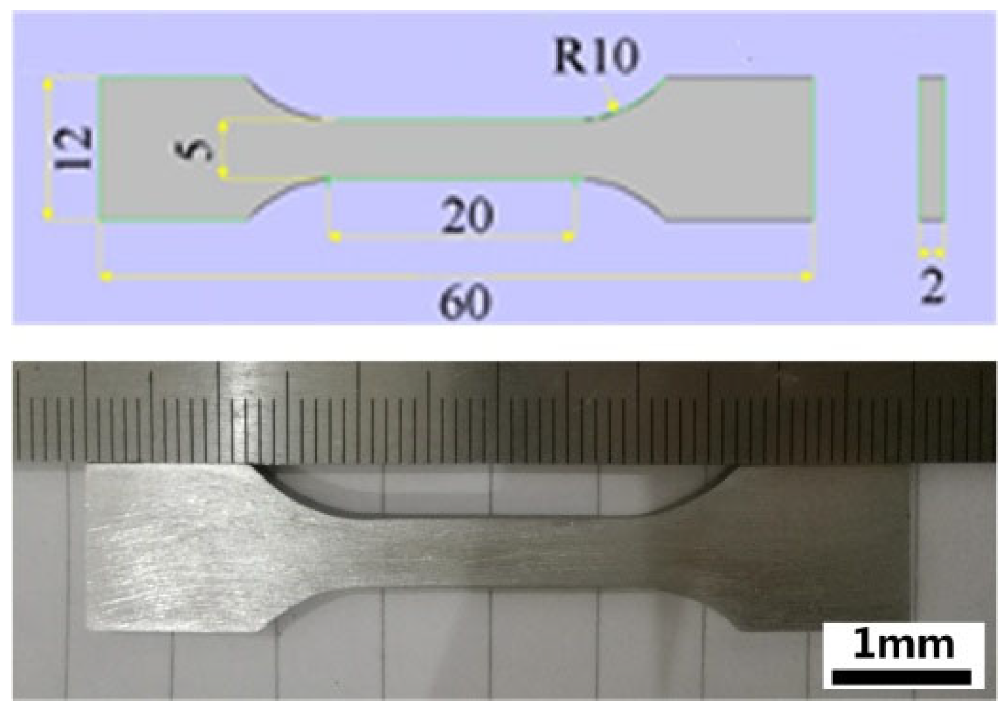
2.2. Microstructural Analysis and Mechanical Tests

The macroscopic microstructure of the sample was observed with a Nikon EPIPHOT 300 metallographic microscope. The sample was pre-ground and then polished. Finally, the polished samples were chemically etched. The etchant was a picric acid solution (5 g picric acid, 5 mL acetic acid, 10 mL deionized water, 100 mL ethanol), and the etching time was 30 s. The FEI Nvo Nano SEM 450 electron microscope was used to observe the microstructure and fracture morphology. In order to study the effect of milling on the microstructure of the magnesium alloy samples, the grain size was measured by the line intercept method [14]. The tensile test instrument was a Shimadzu AGS-X universal material testing machine, used according to the ISO 6892-1-2009 standard. During a tensile test with a tensile speed of 1.5 mm/min, three specimens were taken along the feeding and building directions of the HWMM-produced thin wall, whose dimensions were 12 mm in width, 2 mm in thickness and 60 mm in length, and the model and physical diagram of the tensile specimens are shown in Figure 1. The results reported for the ultimate tensile strength, yield strength and elongation represent the averages for the three specimens. The anisotropic percentages of ultimate tensile strength or elongation corresponds to the ratio of the difference in test values between the building and feeding directions to the value of the feeding direction.

3. Results

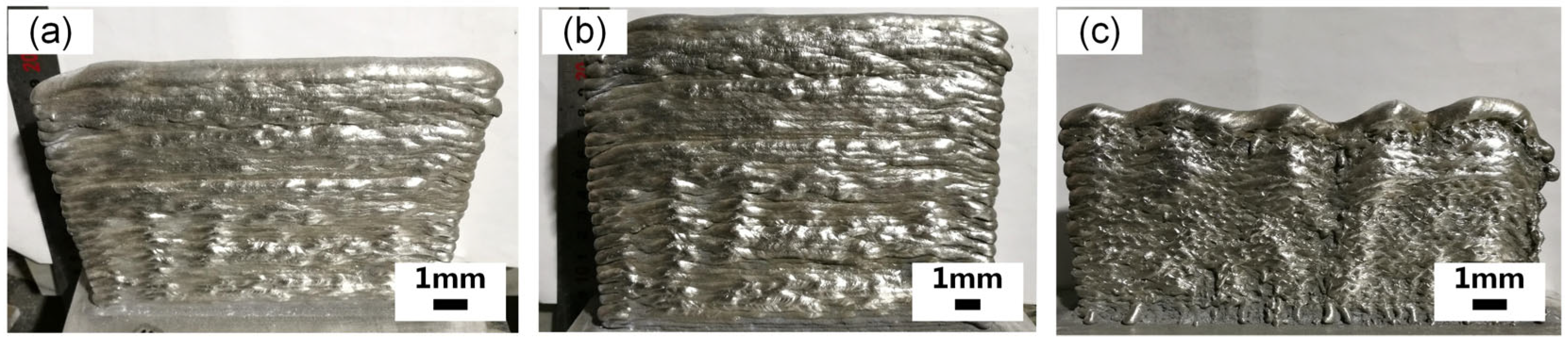
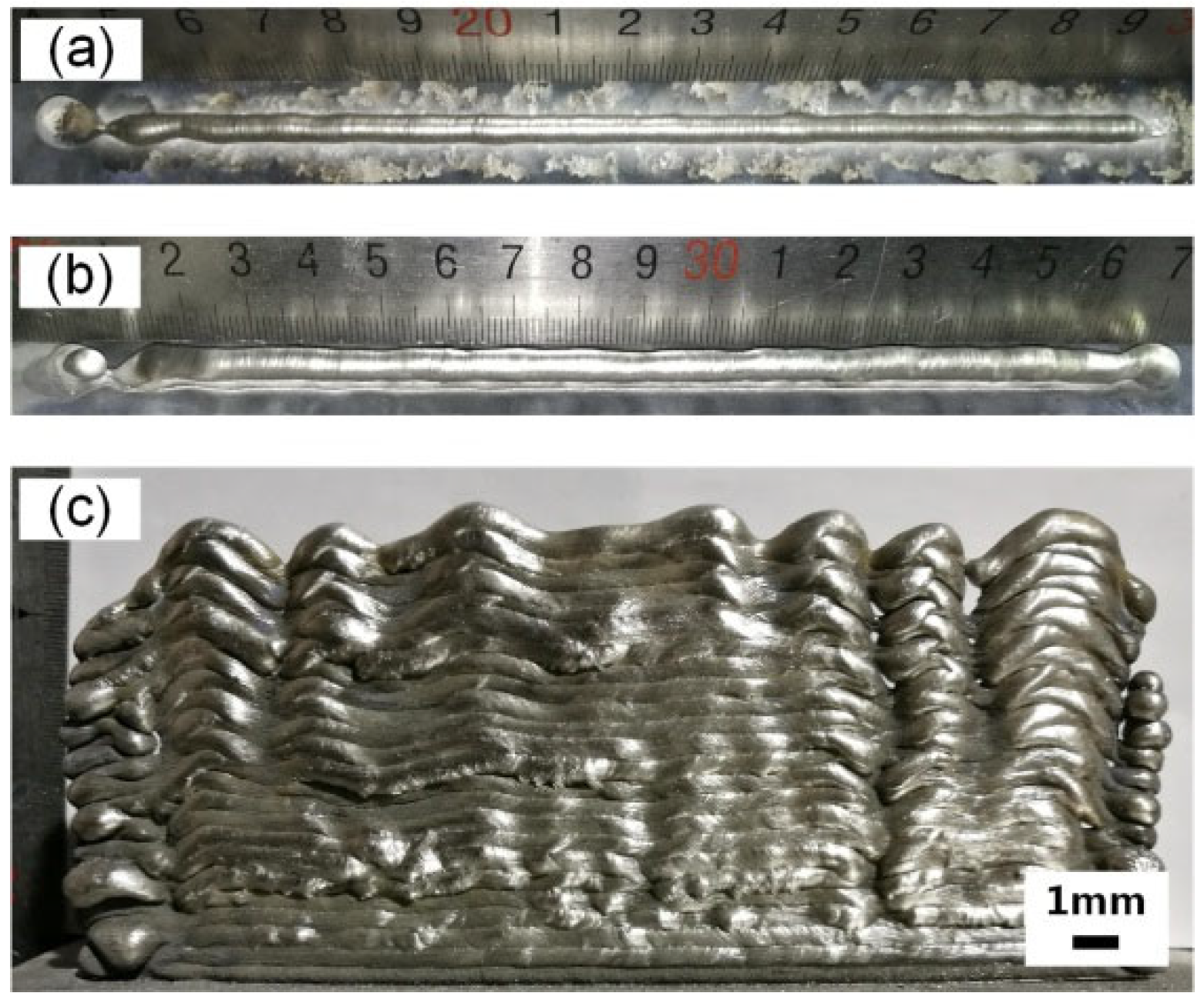
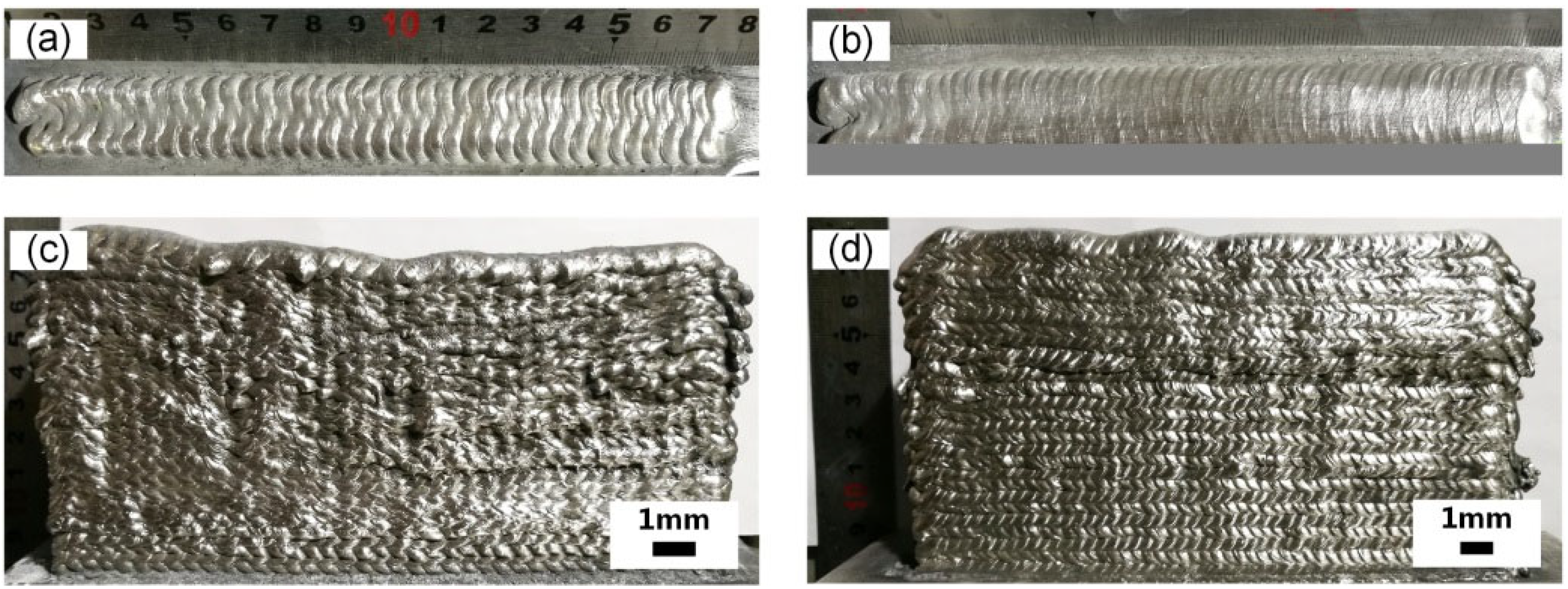
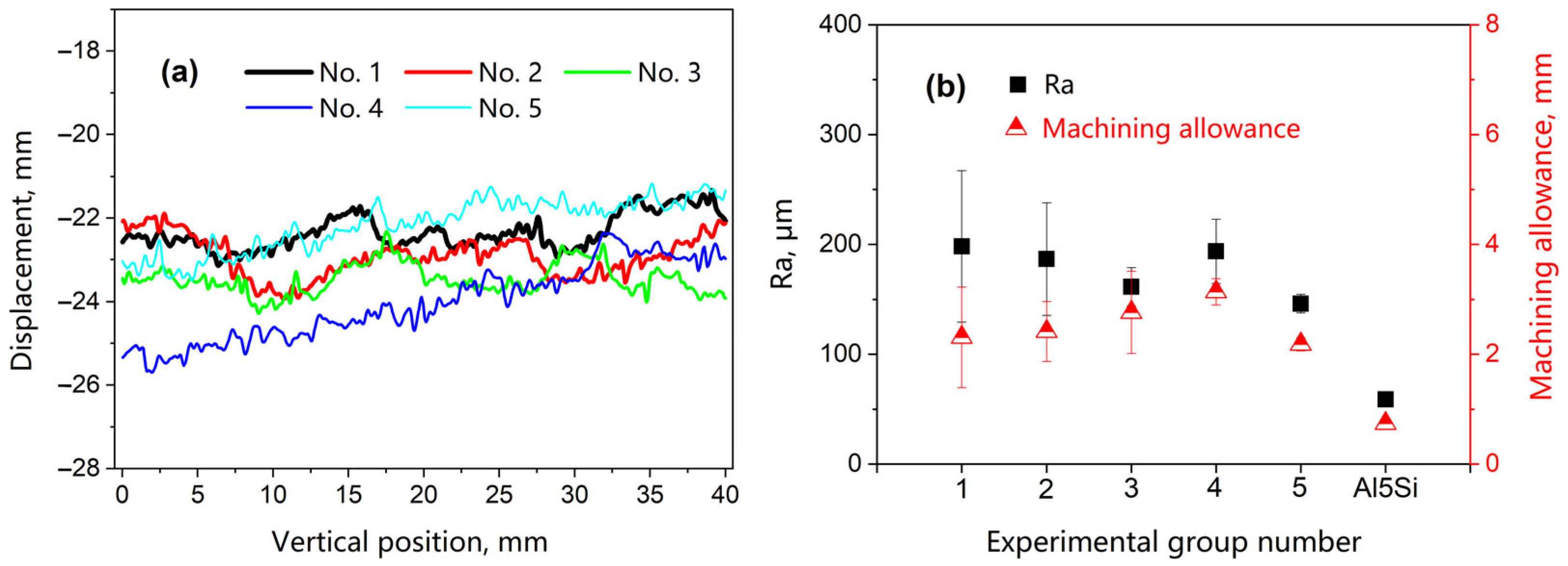
3.1. Macroscopic Analysis and Roughness

Figure 2 is a single thin-walled wall profile obtained using the AlMg4,5Mn CMT process (see Table 2 for the corresponding process parameters of different group numbers). Group 1 and Group 2 were continuously formed at 132.2 mm and 70.9 mm, respectively. It can be seen that the side of the swing-welded specimen is smooth, but the hump phenomenon appears, and the side profile fluctuates greatly. Pure CMT is prone to flow during the deposition process, resulting in a rough local surface.
Figure 3 is the profile of the single thin-walled wall of Group 3 using the Mg alloy CMT process. It can be seen that the CMT mode under the Mg alloy CMT process has a smooth surface, but the spreading effect is poor. When the wire filling speed increases to 7 m/min, the first and the second layers’ morphology is improved, and the fish scale is clearer and more uniform, but the hump still appears in the subsequent forming, resulting in some voids in the sample. The deposited layer surface in the swing welding process is smooth, the spreading effect is better, and the fish scales are clear and evenly distributed.
Figure 4 is the profile of the single thin-walled wall of Group 3 using the Mg alloy CMT process. When the scanning speed is 6 mm/s, the surface of the first layer is not smooth, and the distribution of fish scales is not dense. Local splashing will occur during subsequent forming, resulting in uneven local areas on the side. When the scanning speed is reduced to 4 mm/s, the surface of the first layer is bright and smooth, and the fish scales are densely distributed, so the forming is stable. The side is well distributed with fish scales, and the surface is flat. This shows that the lower scanning speed increases the heat input, which in turn increases the fluidity of the liquid metal.
Figure 5 shows the side-wall scanning contour results of a single thin-walled wall. The surface roughness (Ra) and machining allowance of Group 1 and Group 2 using the AlMg4,5Mn CMT process are not notably different. The Ra and machining allowance of Group 5 using the Mg alloy CMT process are the minimum values, which are 146.1 μm and 2.2 mm, respectively, and they are 24.7% and 29% lower than those of Group 4 (194 μm and 3.1 mm). In addition, the Ra of Group 4 is 90% higher than that of the HWMM-produced Al5Si aluminum sample [31]. At the same time, the Ra and machining allowance of Group 5 are reduced by 21.9% and 4.3%, compared with the minimum value in the AlMg4,5Mn CMT process. In addition, the deviations of Ra and machining allowance in Group 1 are the largest among the four groups, and they are 68.9 μm and 0.9 mm, respectively. The deviation of the Ra and machining allowance in Group 5 is 8.4 μm and 0.1 mm, respectively, being 88.4% and 88.9% lower than that in Group 1. Therefore, the swing welding Mg alloy process deposition is better. This better process parameter includes the wire feeding speed of 12 m/min, the scanning speed of 4 mm/s, the swing welding frequency of 5 Hz, and the amplitude of 8 mm.

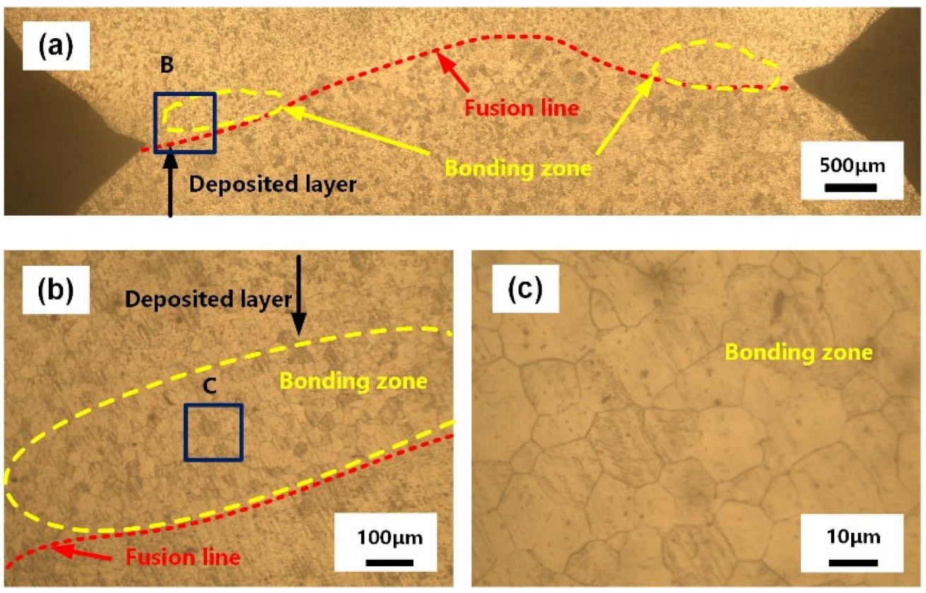
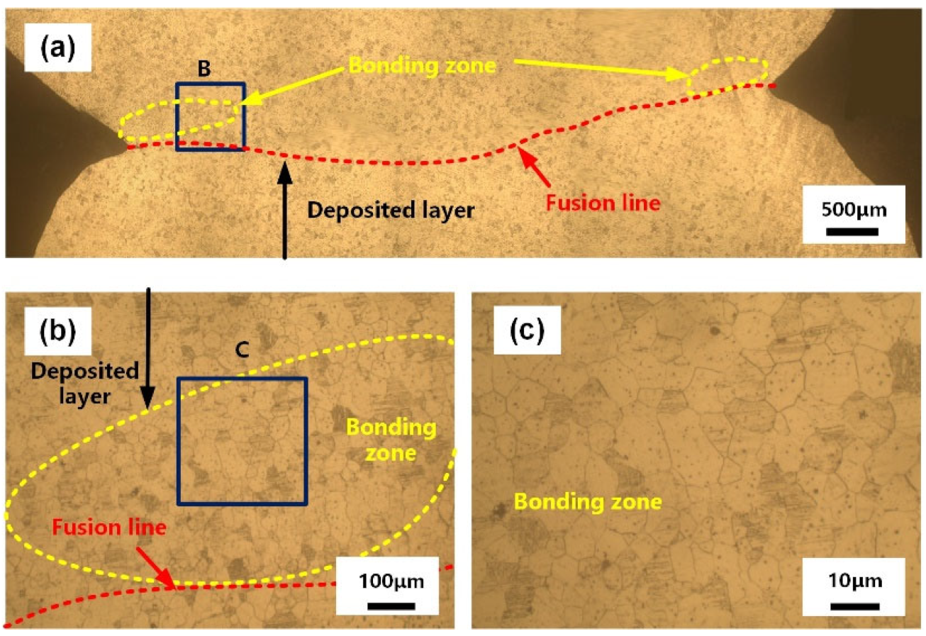
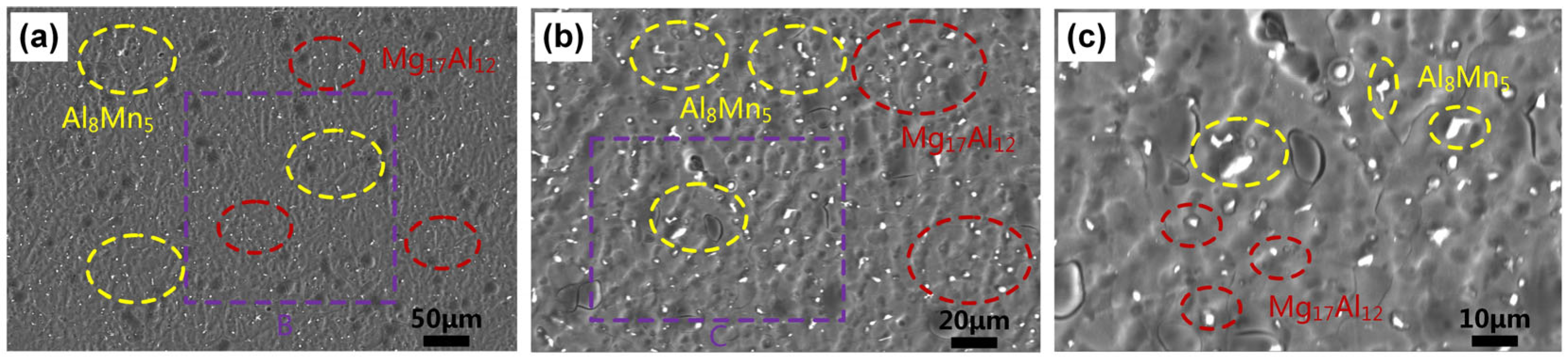
3.2. Microstructural Analysis

Figure 6 shows the cross-section microstructure of the WAAM-processed AZ31B magnesium alloy. It can be seen that the microstructural features of WAAM-processed samples are essentially similar to those of the WAAM-processed Al5Si aluminum alloy [32], which is composed of three parts: a fusion line, deposited layer and bonding zone. The average grain size of the bonding zone is 11.8 μm, which is 56.3% less than that of the deposited layer, and the bonding zones are distributed in the sample edge area, which is consistent with the characteristics of the swing welding path. The fusion line is denoted by the stripes with a convex distribution in Figure 6a.
Figure 7 is the cross-section metallographic diagram of the HWMM-processed AZ31B magnesium alloy sample. It can be seen that the microstructural features of the HWMM-processed samples are also composed of three parts: a fusion line, deposited layer and bonding zone. The fusion line is concave, and the average grain size of the bonding zone increases to 16.2 μm, which is 40% lower than that of the deposited layer. Therefore, the microstructure of the HWMM-processed AZ31B magnesium sample is similar to that of WAAM-processed AZ31B magnesium.
The SEM microstructure of the HWMM-processed sample is shown in Figure 8. It can be seen that α-Mg forms a dark substrate, and white particles of Al8Mn5 and Mg17Al12 of different sizes are distributed on the substrate [19]. The larger granular Al8Mn5 phase is precipitated directly from the liquid phase, and its Al and Mn atoms can aggregate rapidly, while the small granular Mg17Al12 phase is precipitated from the supersaturated α-Mg solid solution.

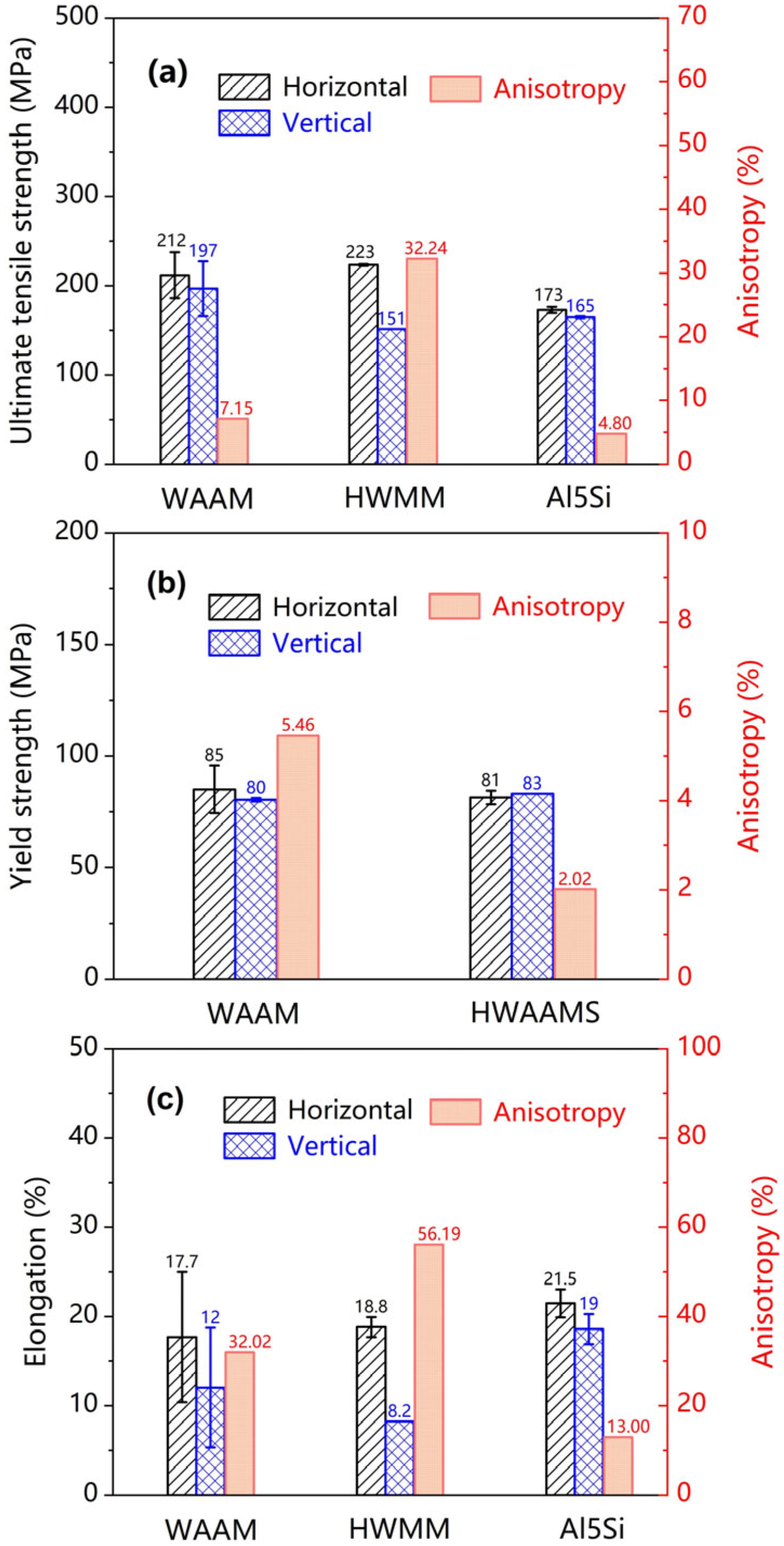
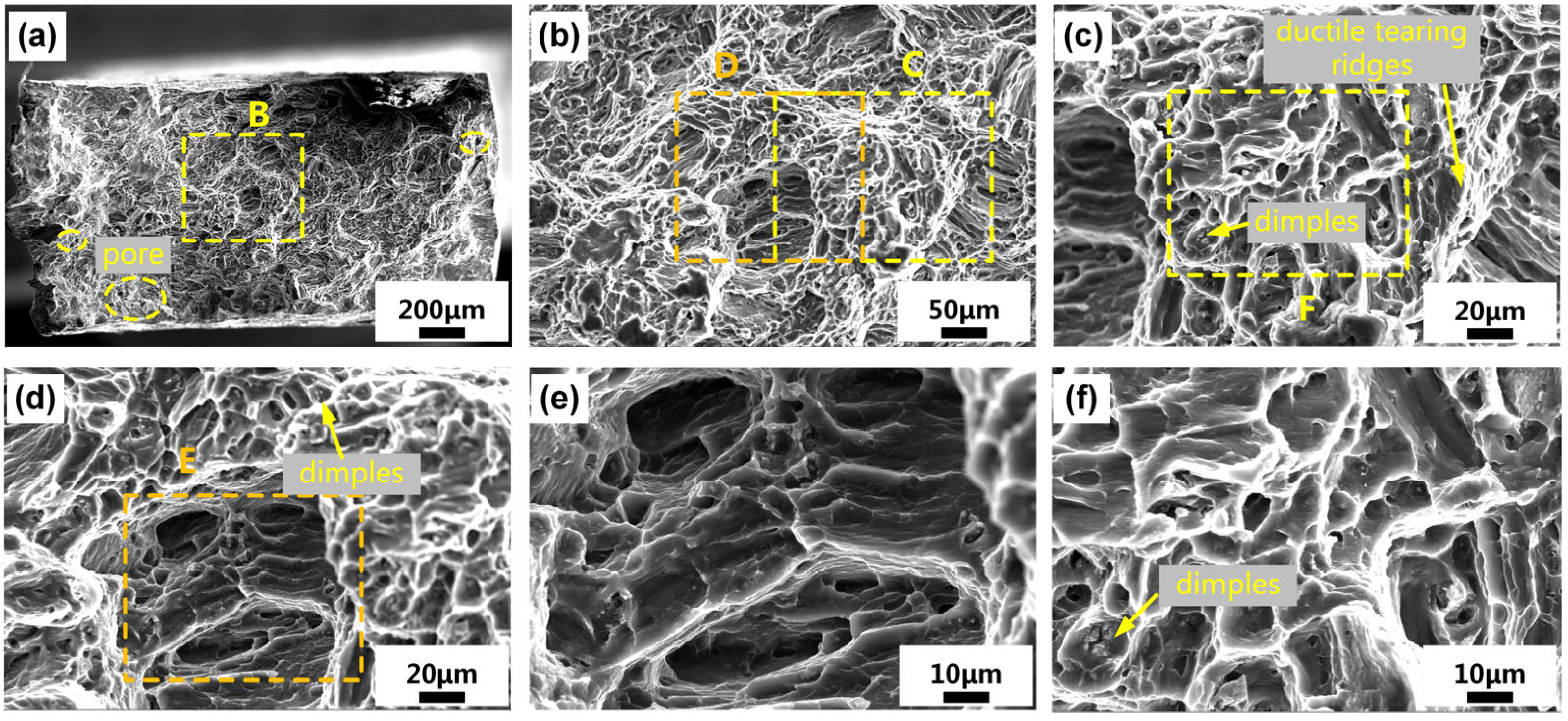
3.3. Tensile Anisotropy and Fractographic Images

As shown in Figure 9, the tensile strength of the HWMM-processed AZ31B magnesium in the horizontal direction is 5.2% higher than that of the WAAM-processed AZ31B magnesium, while the tensile strength of HWMM in the vertical direction is smaller than that of WAAM. Therefore, the anisotropy of HWMM is significantly higher than that of WAAM, and its anisotropy is 32.2%, far greater than 5%. At the same time, the tensile strength deviation of the HWMM-fabricated AZ31B magnesium is smaller than that of the WAAM-fabricated AZ31B magnesium. The yield strength of the HWMM-processed AZ31B magnesium in the horizontal direction is 3.5% lower than that of the WAAM-processed AZ31B magnesium, while the yield strength of the HWMM-processed AZ31B magnesium in the vertical direction is larger than that of the WAAM-processed AZ31B magnesium, so the anisotropy of the HWMM-processed AZ31B magnesium is less than that of the WAAM-fabricated AZ31B magnesium. At this time, the anisotropy of the HWMM-fabricated AZ31B magnesium is 2.0%, less than 5%, and the anisotropy of the yield strength of the HWMM-processed AZ31B magnesium is not significant. The elongation in the horizontal direction of the HWMM-processed AZ31B magnesium is smaller than that of the WAAM-processed AZ31B magnesium, and the elongation in the vertical direction is 30.8% lower than that of the WAAM-processed AZ31B magnesium. At the same time, the elongation anisotropy of the HWMM-fabricated AZ31B magnesium is 56.2%, which is far greater than 5%. The difference in elongation is significantly credible. The tensile strength and elongation anisotropy of the HWMM-processed Al5Si aluminum alloy is 4.8% and 13%, respectively [32]. The anisotropy in the tensile strength and elongation of the AZ31B sample was 32% and 56%, respectively, being 6 and 3.3 times higher than that of the Al5Si samples.
It can be seen from Figure 10 that the fracture has typical dimples and ductile tearing edge characteristics, and some pores are found on the fracture. The fracture morphology shows that these dimples are formed by the plastic flow of the matrix (α-Mg), while the eutectic composition or intermetallic compound phase remains unchanged at the center of each dimple. However, gas holes may be formed during HWMM processing due to oxidation or impurities in the wire. In a few cases, individual grains fracture in a brittle manner, which is likely to occur in grains perpendicular to the tensile direction [33].

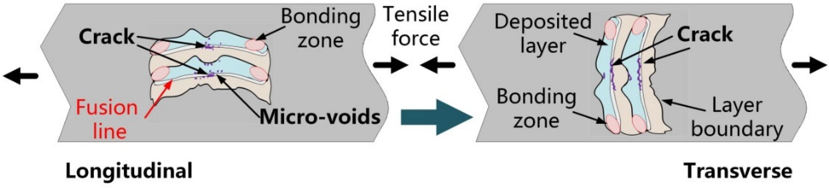
4. Mechanisms of Tensile Anisotropic Difference

As mentioned above, the microstructural features of the HWMM-produced magnesium alloy sample are similar to those of aluminum alloy. The AZ31B magnesium alloy studied in this paper has a fine-grained equiaxed structure similar to that reported in the literature [14,17]. In the HWMM, the AZ31B magnesium alloy alloyed with Al can easily form fine and equiaxed grains [34]. Due to the difference in thermal boundary conditions at different positions, the solidification rate is different so that an obvious layered structure is formed. Therefore, based on the key factor in the formation of a fine equiaxed microstructure according to the interdependence theory proposed by Birmingham, this morphology usually leads to tensile anisotropy [35].
From the analysis of the tensile fracture mechanism of the HWMM aluminum alloy, it can be seen that the fusion line area of the sample is prone to fracture during the tensile process due to the obvious uneven structure [32]. The physical parameters of the AZ31B magnesium alloy and the Al5Si aluminum alloy are shown in Table 3. From the table, it can be found that the thermal conductivity of the AZ31B magnesium alloy is 0.39 times that of the Al5Si aluminum alloy, and the solidus temperature of the AZ31B magnesium alloy is 29.8% lower than that of the Al5Si aluminum alloy. These differences lead to a more obvious uneven microstructure near the fusion line of the AZ31B magnesium alloy, and the grain size difference between adjacent areas reaches 40%. At the same time, the chemical activity of the AZ31B magnesium alloy is much higher than that of the Al5Si aluminum alloy.
During the forming process of magnesium alloy, it is easy to observe oxides formed on the surface, resulting in some defects such as incomplete fusion and porosity. It leads to the fracture of the magnesium alloy near the fusion line, which occurs more easily than in aluminum alloy during the tensile process, as shown in Figure 11. Therefore, the tensile property decrease in magnesium alloy along the deposition direction is larger than that in aluminum alloy. The tensile properties along the feed direction are less affected by the uneven structure near the fusion line. As a result, the tensile strength and elongation anisotropy of the AZ31B magnesium alloy samples is larger than those of the Al5Si aluminum alloy.

5. Conclusions

(1)
The hybrid wire arc additive-milling subtractive manufacturing (HWMM) of the AZ31B magnesium alloy was proposed for the first time, and the deposition accuracy was compared with that of the Al5Si aluminum alloy. Under the optimal process parameters, the surface roughness of the AZ31B magnesium sample was 146.1 μm, which is 90% higher than that of the Al5 Si aluminum sample.
(2)
The microstructural features of the HWMM AZ31B magnesium alloy sample are essentially similar to those of the Al5Si aluminum alloy. The microstructure of the HWMM AZ31B magnesium alloy sample is consistent with that of arc wire additive manufacturing, and white particles of Al8Mn5 and Mg17Al12 with different sizes are distributed on the substrate. In addition, the anisotropy in the tensile strength and elongation of AZ31B magnesium sample was 32% and 56%, respectively, being 6 and 3.3 times higher than in the Al5Si aluminum samples.
(3)
According to the fracture behaviors, the tensile anisotropy of aluminum alloy and magnesium alloy was mainly attributed to defect, such as incomplete fusion and porosity in the fusion line. However, because the thermal conductivity of the AZ31B magnesium alloy was 0.39 times that of the Al5Si aluminum alloy, the structural inhomogeneity in the AZ31B magnesium samples was more obvious, and the grain size difference between adjacent areas reached 40%. This led to the easier fracture of the AZ31B magnesium samples.

Author Contributions

Methodology, S.Z. and M.G. (Ming Gao); Validation, M.G. (Mengcheng Gong); Investigation, S.Z. and Y.L.; Resources, S.Z. and M.G. (Mengcheng Gong); Data curation, S.Z. and L.C.; Writing—original draft, S.Z. and M.G. (Ming Gao); Writing—review & editing, M.G. (Ming Gao); Visualization, S.Z.; Project administration, M.G. (Ming Gao); Funding acquisition, S.Z. All authors have read and agreed to the published version of the manuscript.

Funding

This research was financially supported by the National Natural Science Foundation of China (Grant No: 52275335, 52205360 and Grant No: 52205465).

Institutional Review Board Statement

Not applicable.

Informed Consent Statement

Not applicable.

Data Availability Statement

The data presented in this study are available upon request from the corresponding author.

Conflicts of Interest

The authors declare no conflict of interest.

References

  1. Mordike, B.; Ebert, T. Magnesium: Properties—Applications—Potential. Mater. Sci. Eng. A 2001, 302, 37–45. [Google Scholar] [CrossRef]
  2. Sahoo, K.; Poddar, P. Studies on Magnesium Alloys–Properties and Potential for Automotive and Aerospace Applications, Transaction of 65th Indian foundry Congress 2017. In Proceedings of the Transaction of 65th Indian foundry Congress 2017, Kolkata, India, 3–5 February 2017; Volume 2017, pp. 151–156. [Google Scholar]
  3. Luo, A.A. Materials Comparison and Potential Applications of Magnesium in Automobiles, Essential Readings in Magnesium Technology; Springer: Berlin/Heidelberg, Germany, 2016; pp. 25–34. [Google Scholar]
  4. Galy, C.; Le Guen, E.; Lacoste, E.; Arvieu, C. Main defects observed in aluminum alloy parts produced by SLM: From causes to consequences. Addit. Manuf. 2018, 22, 165–175. [Google Scholar] [CrossRef]
  5. Leary, M.; Mazur, M.; Elambasseril, J.; McMillan, M.; Chirent, T.; Sun, Y.; Qian, M.; Easton, M.; Brandt, M. Selective laser melting (SLM) of AlSi12Mg lattice structures. Mater. Des. 2016, 98, 344–357. [Google Scholar] [CrossRef]
  6. DebRoy, T.; Wei, H.; Zuback, J.; Mukherjee, T.; Elmer, J.; Milewski, J.; Beese, A.M.; Wilson-Heid, A.; De, A.; Zhang, W. Additive manufacturing of metallic components–Process, structure and properties. Prog. Mater. Sci. 2018, 92, 112–224. [Google Scholar] [CrossRef]
  7. Jafari, D.; Vaneker, T.H.; Gibson, I. Wire and arc additive manufacturing: Opportunities and challenges to control the quality and accuracy of manufactured parts. Mater. Des. 2021, 202, 109471. [Google Scholar] [CrossRef]
  8. Kazanas, P.; Deherkar, P.; Almeida, P.; Lockett, H.; Williams, S. Fabrication of geometrical features using wire and arc additive manufacture. Proc. Inst. Mech. Eng. Part B J. Eng. Manuf. 2012, 226, 1042–1051. [Google Scholar] [CrossRef]
  9. Zeng, Z.; Salehi, M.; Kopp, A.; Xu, S.; Esmaily, M.; Birbilis, N. Recent progress and perspectives in additive manufacturing of magnesium alloys. J. Magnes. Alloys 2022, 10, 1511–1541. [Google Scholar] [CrossRef]
  10. Song, J.; Chen, J.; Xiong, X.; Peng, X.; Chen, D.; Pan, F. Research advances of magnesium and magnesium alloys worldwide in 2021. J. Magnes. Alloys 2022, 10, 863–898. [Google Scholar] [CrossRef]
  11. Pan, F.; Yang, M.; Chen, X. A Review on Casting Magnesium Alloys: Modification of Commercial Alloys and Development of New Alloys. J. Mater. Sci. Technol. 2016, 32, 1211–1221. [Google Scholar] [CrossRef]
  12. Song, J.; Pan, F.; Jiang, B.; Atrens, A.; Zhang, M.-X.; Lu, Y. A review on hot tearing of magnesium alloys. J. Magnes. Alloy. 2016, 4, 151–172. [Google Scholar] [CrossRef] [Green Version]
  13. Takagi, H.; Sasahara, H.; Abe, T.; Sannomiya, H.; Nishiyama, S.; Ohta, S.; Nakamura, K. Material-property evaluation of magnesium alloys fabricated using wire-and-arc-based additive manufacturing. Addit. Manuf. 2018, 24, 498–507. [Google Scholar] [CrossRef]
  14. Guo, J.; Zhou, Y.; Liu, C.; Wu, Q.; Chen, X.; Lu, J. Wire arc additive manufacturing of AZ31 magnesium alloy: Grain refinement by adjusting pulse frequency. Materials 2016, 9, 823. [Google Scholar] [CrossRef] [Green Version]
  15. Yang, X.; Liu, J.; Wang, Z.; Lin, X.; Liu, F.; Huang, W.; Liang, E. Microstructure and mechanical properties of wire and arc additive manufactured AZ31 magnesium alloy using cold metal transfer process. Mater. Sci. Eng. A 2020, 774, 138942. [Google Scholar] [CrossRef]
  16. Bi, J.; Shen, J.; Hu, S.; Zhen, Y.; Yin, F.; Bu, X. Microstructure and mechanical properties of AZ91 Mg alloy fabricated by cold metal transfer additive manufacturing. Mater. Lett. 2020, 276, 128185. [Google Scholar] [CrossRef]
  17. Wang, P.; Zhang, H.; Zhu, H.; Li, Q.; Feng, M. Wire-arc additive manufacturing of AZ31 magnesium alloy fabricated by cold metal transfer heat source: Processing, microstructure, and mechanical behavior. J. Mater. Process. Technol. 2021, 288, 116895. [Google Scholar] [CrossRef]
  18. Klein, T.; Arnoldt, A.; Schnall, M.; Gneiger, S. Microstructure formation and mechanical properties of a wire-arc additive manufactured magnesium alloy. JOM 2021, 73, 1126–1134. [Google Scholar] [CrossRef]
  19. Gao, M.; Cen, L.; Jiang, L.; Zhao, S.; Gong, M. Oscillating laser-arc hybrid additive manufacturing of AZ31 magnesium alloy. Appl. Sci. 2022, 13, 897. [Google Scholar] [CrossRef]
  20. Prado-Cerqueira, J.; Diéguez, J.; Camacho, A. Preliminary development of a Wire and Arc Additive Manufacturing system (WAAM). Procedia Manuf. 2017, 13, 895–902. [Google Scholar] [CrossRef]
  21. González, J.; Rodríguez, I.; Prado-Cerqueira, J.-L.; Diéguez, J.; Pereira, A. Additive manufacturing with GMAW welding and CMT technology. Procedia Manuf. 2017, 13, 840–847. [Google Scholar] [CrossRef]
  22. Campatelli, G.; Montevecchi, F.; Venturini, G.; Ingarao, G.; Priarone, P.C. Integrated WAAM-subtractive versus pure subtractive manufacturing approaches: An energy efficiency comparison. Int. J. Precis. Eng. Manuf. Technol. 2020, 7, 1–11. [Google Scholar] [CrossRef]
  23. Priarone, P.C.; Campatelli, G.; Montevecchi, F.; Venturini, G.; Settineri, L. A modelling framework for comparing the environmental and economic performance of WAAM-based integrated manufacturing and machining. CIRP Ann. 2019, 68, 37–40. [Google Scholar] [CrossRef]
  24. Xiong, X.; Zhang, H.; Wang, G.; Wang, G. Hybrid plasma deposition and milling for an aeroengine double helix integral impeller made of superalloy. Robot. Comput.-Integr. Manuf. 2010, 26, 291–295. [Google Scholar] [CrossRef]
  25. Xiong, X.; Zhang, H.; Wang, G. Metal direct prototyping by using hybrid plasma deposition and milling. J. Mater. Process. Technol. 2009, 209, 124–130. [Google Scholar] [CrossRef]
  26. Afazov, S.; Ceesay, L.; Larkin, O.; Berglind, L.; Denmark, W.; Ozturk, E. A methodology for precision manufacture of a nozzle using hybrid laser powder-bed fusion: A case study. Proc. Inst. Mech. Eng. Part B J. Eng. Manuf. 2021, 235, 751–760. [Google Scholar] [CrossRef]
  27. Wüst, P.; Edelmann, A.; Hellmann, R. Areal surface roughness optimization of maraging steel parts produced by hybrid additive manufacturing. Materials 2020, 13, 418. [Google Scholar] [CrossRef] [Green Version]
  28. Li, P.; Gong, Y.; Wen, X.; Xin, B.; Liu, Y.; Qu, S. Surface residual stresses in additive/subtractive manufacturing and electrochemical corrosion. Int. J. Adv. Manuf. Technol. 2018, 98, 687–697. [Google Scholar] [CrossRef]
  29. Li, F.; Chen, S.; Shi, J.; Tian, H.; Zhao, Y. Evaluation and optimization of a hybrid manufacturing process combining wire arc additive manufacturing with milling for the fabrication of stiffened panels. Appl. Sci. 2017, 7, 1233. [Google Scholar] [CrossRef] [Green Version]
  30. Ma, G.; Zhao, G.; Li, Z.; Yang, M.; Xiao, W. Optimization strategies for robotic additive and subtractive manufacturing of large and high thin-walled aluminum structures. Int. J. Adv. Manuf. Technol. 2019, 101, 1275–1292. [Google Scholar] [CrossRef]
  31. Zhang, S.; Zhang, Y.; Gao, M.; Wang, F.; Li, Q.; Zeng, X. Effects of milling thickness on wire deposition accuracy of hybrid additive/subtractive manufacturing. Sci. Technol. Weld. Join. 2019, 24, 375–381. [Google Scholar] [CrossRef]
  32. Zhang, S.; Gong, M.; Zeng, X.; Gao, M. Residual stress and tensile anisotropy of hybrid wire arc additive-milling subtractive manufacturing. J. Mater. Process. Technol. 2021, 293, 117077. [Google Scholar] [CrossRef]
  33. Zumdick, N.A.; Jauer, L.; Kersting, L.C.; Kutz, T.N.; Schleifenbaum, J.H.; Zander, D. Additive manufactured WE43 magnesium: A comparative study of the microstructure and mechanical properties with those of powder extruded and as-cast WE43. Mater. Charact. 2019, 147, 384–397. [Google Scholar] [CrossRef]
  34. St, J.D.H.; Qian, M.; Easton, M.A.; Cao, P.; Hildebrand, Z. Grain refinement of magnesium alloys. Met. Mater. Trans. A 2005, 36, 1669–1679. [Google Scholar]
  35. Bermingham, M.; StJohn, D.; Easton, M.; Yuan, L.; Dargusch, M. Revealing the Mechanisms of Grain Nucleation and Formation During Additive Manufacturing. JOM 2020, 72, 1065–1073. [Google Scholar] [CrossRef]
  36. Davis, J.R. Metals Handbook, 9th ed.; ASM International: Chardon, OH, USA, 1979. [Google Scholar]
  37. Koklu, U.; Coban, H. Effect of dipped cryogenic approach on thrust force, temperature, tool wear and chip formation in drilling of AZ31 magnesium alloy. J. Mater. Res. Technol. 2020, 9, 2870–2880. [Google Scholar] [CrossRef]
  38. Li, Y. Light Metal Welding Technology; National Defense Industry Press: Beijing, China, 2011; pp. 145–146. [Google Scholar]
Figure 1. Model and physical diagram of tensile specimen.
Applsci 13 02720 g001
Figure 2. Side-wall morphology of magnesium deposited sample: (a) overview of No. 1, (b) No. 1, (c) No. 2.
Applsci 13 02720 g002
Figure 3. Side-wall profile of No. 3: (a) first layer, (b) second layer, (c) overview.
Applsci 13 02720 g003
Figure 4. Single layer morphology, (a) No. 4, (b) No. 5; overview, (c) No. 4, (d) No. 5.
Applsci 13 02720 g004
Figure 5. (a) Side-wall scanning contour, (b) surface roughness (Ra) and machining allowance.
Applsci 13 02720 g005
Figure 6. OM image of the AZ31B magnesium alloy cross-section specimen fabricated by WAAM: (a) overview, (b) details of region B, (c) details of region C.
Applsci 13 02720 g006
Figure 7. OM image of the AZ31B magnesium alloy cross-section specimen fabricated with HWMM: (a) overview, (b) details of region B, (c) details of region C.
Applsci 13 02720 g007
Figure 8. SEM micrographs of HWMM-fabricated AZ31B magnesium alloy sample. Al8Mn5 and Mg17Al12 are marked with yellow and red dots: (a) overview, (b) details of region B, (c) details of region C.
Applsci 13 02720 g008
Figure 9. Tensile anisotropy of the HWMM-processed AZ31B magnesium, (a) ultimate tensile strength, (b) yield Tensile, (c) elongation.
Applsci 13 02720 g009
Figure 10. SEM micrographs of sample 7 tensile fracture: (a) overview, (b) details of region B, (c) details of region C, (d) details of region D, (e) details of region E, (f) details of region F.
Applsci 13 02720 g010
Figure 11. Schematic diagram of the HWMM-produced AZ31B magnesium sample fracture mechanisms.
Applsci 13 02720 g011
Table 1. Chemical compositions of AZ31B wire/wt-%.
MaterialAlZnMnSiFeCuNiMg
AZ31B2.80.990.250.0190.00270.00760.00071Balance
Table 2. Main processing parameters in the HWMM experiment.
No.CMT
Process
Deposition ModeSwing WeldingWire Filling Speed
m/min
Scanning Speed
mm/s
Arc
Current
A
Arc
Voltage
V
Frequency
Hz
Amplitude
mm
1AlMg4,5MnCMT689313.3
2AlMg4,5MnSwing welding53689313.3
3Mg alloyCMT7109010.6
4Mg alloySwing welding5812614913.1
5Mg alloySwing welding5812414913.1
Table 3. Physical parameters of magnesium alloy and aluminum alloy.
Physical ParametersMgAl [36]
Density, kg/m31770 [37]2700
Poisson ratio0.35 [37]0.33
Young’s modulu, GPa45.0 [37]69.4
Solidus temperature, °C566 [38]806.4
Thermal conductivity, W/(m·k)96 [3]247
Specific heat capacity, J/(kg·K)1000 [38]963
Coefficient of linear expansion, m/m·°C2.6 × 10−5 [3]2.4 × 10⁻⁵
Disclaimer/Publisher’s Note: The statements, opinions and data contained in all publications are solely those of the individual author(s) and contributor(s) and not of MDPI and/or the editor(s). MDPI and/or the editor(s) disclaim responsibility for any injury to people or property resulting from any ideas, methods, instructions or products referred to in the content.

