Article

Multi-Robot Collaborative Flexible Manufacturing and Digital Twin System Design of Circuit Breakers

1
Engineering Research Center of Low-Voltage Apparatus Technology of Zhejiang Province, Wenzhou University, Wenzhou 325035, China
2
Technology Institute, Wenzhou University, Wenzhou 325699, China
*
Author to whom correspondence should be addressed.
Appl. Sci. 2023, 13(4), 2721; https://doi.org/10.3390/app13042721
Submission received: 31 January 2023 / Revised: 12 February 2023 / Accepted: 16 February 2023 / Published: 20 February 2023
(This article belongs to the Topic Virtual Reality, Digital Twins, the Metaverse)

Abstract

:
Circuit breakers (CBs) are mainly designed to interrupt current flow when faults are detected and have been widely used in industrial applications. The existing CBs manufacturing method is semi-automatic and requires a lot of labor. To realize flexible manufacturing, a multi-robot cooperative CBs flexible manufacturing system (CBFMS) is presented in this study. Aiming at the efficiency of the multi-robot cooperative CBFMS key units, a two-arm cooperation robot approach is proposed. The reinforcement learning algorithm is developed to optimize the manufacturing trajectory of the two-arm cooperation robot. To build and optimize the multi-robot cooperative CBFMS, a digital twin (DT) system describing all physical properties of the physical manufacturing plant is constructed for simulation. In the developed DT system, a kinematic control model of the collaboration robot is established. A real-time display of the robot’s trajectory, manufacturing status, and process manufacturing is provided by the data interaction with the physical cell flow between the units. Following this design, a synchronous mapping between the flexible manufacturing DT system of the CBs and the physical workshop is realized, which enables real-time monitoring and management of the physical production line. The experiments’ results show that the manufacturing efficiency, compared with traditional CBs production, is improved by 22%. Moreover, the multi-robot cooperative CBFMS can make process changes according to the production requirements, which can improve the stability of production.

1. Introduction

Circuit breaker [1,2] is an important component of the electrical industry, which plays an important role in production and manufacturing. Most of the traditional CBs manufacturing is performed with semi-automated production. Most of the assembly operations cannot be completed with robots. To achieve high manufacturing efficiency, the concept of flexible CBs manufacturing has been developed. With the development of the Industry 4.0 era [3], industrial robots are developed for flexible manufacturing systems (FMS) because of their high flexibility and operability [4]. At present, several problems still exist in CBs manufacturing when assembly robots are incorporated: (1) a proper assembly process is usually missing, which results in relatively low production efficiency; (2) collaborative robots in motion control and trajectory optimization are still facing many challenges [5,6,7,8]. Digital twin (DT) technology is mainly applied in aerospace applications. In addition, the DT system can be applied to the design, development, manufacturing, assembly, operation, and maintenance of aircraft [9,10,11,12]. With the development of manufacturing, DT technology is beginning to be integrated into intelligent manufacturing. It can effectively improve the production conditions and intelligence level. To solve the problems of adaptability and human dynamics, a DT system in the field of automation was proposed. By introducing the structure, manifestation, and existing advantages of the DT system, some reasonable suggestions for future development are put forward [13]. To solve the dynamic problems in the production system and make the DT model design more perfect, a DT model for the development of a production system is proposed to analyze and optimize the process parameters by extracting data from the physical unit production line. This method can realize the remote monitoring of the production system and improve the performance of the system [14]. A DT prototype method is proposed to help humans complete welding training. This method analyzes behavior through data-driven processes and displays the behavior through Augmented Reality (AR). The results show that this method can effectively solve the problems encountered by human behavior in welding and can improve the user’s sense of operation and comfort [15]. Collaborative robots are lightweight, perceptive, and highly maneuverable [16,17]. Robots can sense their surroundings and change their behavior in response to the environment, which can make work easier and improve the performance indicators. To enable robots to complete various complex tasks and improve the cooperation ability of a multi-robot system, a human–machine collaborative assembly scheme without sensors was proposed. The compliance control of the cooperative robot is completed by optimizing the identification method of the load model and the adaptive impedance algorithm determined by the design task [18]. Aiming at the difficult problems of large assembly workload and high requirement for hole-making quality and precision in the narrow space of the aircraft, a dual-robot guidance-cooperative operation intelligent control technology for the narrow space of the aircraft is proposed. Through trajectory planning of the robot and compensation of the collaborative visual servo control, the target assembly and assembly space occupation are achieved [19]. However, existing problems, such as the manufacturing accuracy and safety issues, still need to be solved. Therefore, the combination of DT technology and multi-robot technology can promote the development of intelligent manufacturing and improve the level of intelligence.
In recent years, the application of multi-robot cooperation and DT technology has become more and more extensive. Tao [20] et al., put forward the concept of the DT workshop for intelligent production needs and explored the new concept of the workshop based on DT. They discussed four essential parts: the physical workshop, virtual workshop, workshop service system, and DT data. Furthermore, the data transfer service’s operational mechanism and implementation method are studied to lay a theoretical foundation for constructing the DT workshop. However, the research is at an initial stage and still needs a lot of work, such as the applications of a DT workshop in smart manufacturing. Pérez [21] et al., proposed a multi-robot system, which can combine robots from different manufacturers. The system is modeled, designed automatically, and monitored in real time through a DT system. Meanwhile, it is well suited for operator training, real-time monitoring, and optimization. However, this method does not involve real-time connection between the twin system and the physical system, and some functions have not been realized. Han [22] et al., proposed a flexible automatic assembly of CBs by using a robot system. To optimize the assembly trajectory of the manipulator, quintic polynomial interpolation is combined with particle swarm optimization (PSO). However, all experimental verifications are based on a platform for testing, and there is a lack of digital simulation methods for verification. In Ref [23], a framework that supports robot motion planning and motion control based on the DT technique was proposed. Aiming at a flexible assembly robot unit, a mathematical model of robot motion control was then applied to the digital scene of the physical object. The digital model was kept up to date by continuously mirroring the physical units driven by data, thus ensuring the real-time synchronization and faithful mapping of digital twins. However, the research is limited to the design of the robot unit and does not involve the design of the entire flexible manufacturing process of CBs. Moreover, the operation mode was also limited to a single-robot system, which cannot realize flexible automatic production of CBs. In Ref [24], to solve the trajectory planning problem of multiple robots in common welding, a hierarchical planning control strategy with a symmetric internal and external adaptive variable impedance control method is proposed. Although the method can successfully complete the welding of the target, there are certain safety problems during the operation, and the actual operation is difficult. In Refs [25,26], a deep Q-network (DQN) algorithm in reinforcement learning is applied to the multi-robot system. Compared with the traditional machine-learning algorithm, it can solve the path planning problem faster and more effectively. However, this method has problems, such as low sample utilization and inability to handle continuous actions.
The existing research shows that the current CBs manufacturing solutions are mainly semi-automatic, and there is a lack of fully automated and flexible system solutions. Due to the limited capability of a single-robot system, the system beat is affected by the lead time (LT), the actual Takt time (ATT), and the cycle time (CT). In addition, there is a lack of a complete set of digital devices to supervise and optimize the manufacturing system. Compared with existing research, the main innovations and contributions of our study consist of three parts:
  • To realize the flexible assembly of a circuit breaker, a multi-robot collaborative CBFMS is designed in this paper. Compared with traditional assembly methods, it can achieve efficient assembly and enhance system stability.
  • To improve the assembly efficiency of CBFMS key units and improve the production rhythm of the system, a two-arm cooperation robot method is designed. The training robot is assembled using the depth deterministic strategy gradient (DDPG) algorithm [27,28,29]. Compared with other machine-learning algorithms, DDPG can learn continuous actions more effectively, thus improving the stability and convergence of the system.
  • To monitor and optimize the production unit, a DT system is developed to synchronize the virtual unit by interacting with the physical production unit. Compared with the traditional manufacturing method, the production line can be planned and adjusted through simulation of the DT system to ensure the efficiency and safety of production.
The paper is organized as follows. The composition of a multi-robot cooperative CBFMS and the design framework of the DT system are introduced in Section 2. In Section 3, a two-arm cooperation robot assembly part method is proposed; feasibility is verified by collaborative space analysis and algorithm optimization of the assembly trajectory. In Section 4, the construction and optimization of the DT system based on multi-robot cooperative CBFMS are introduced. The experiment and analysis are carried out in Section 5. The conclusions are given in Section 6.

2. Related Work

The internal structure and the components of the CBs are shown in Figure 1. Five parts (handle, big-U rod, yoke, magnetic system, arc extinguishing chamber) are selected as the objects to be assembled in this paper.

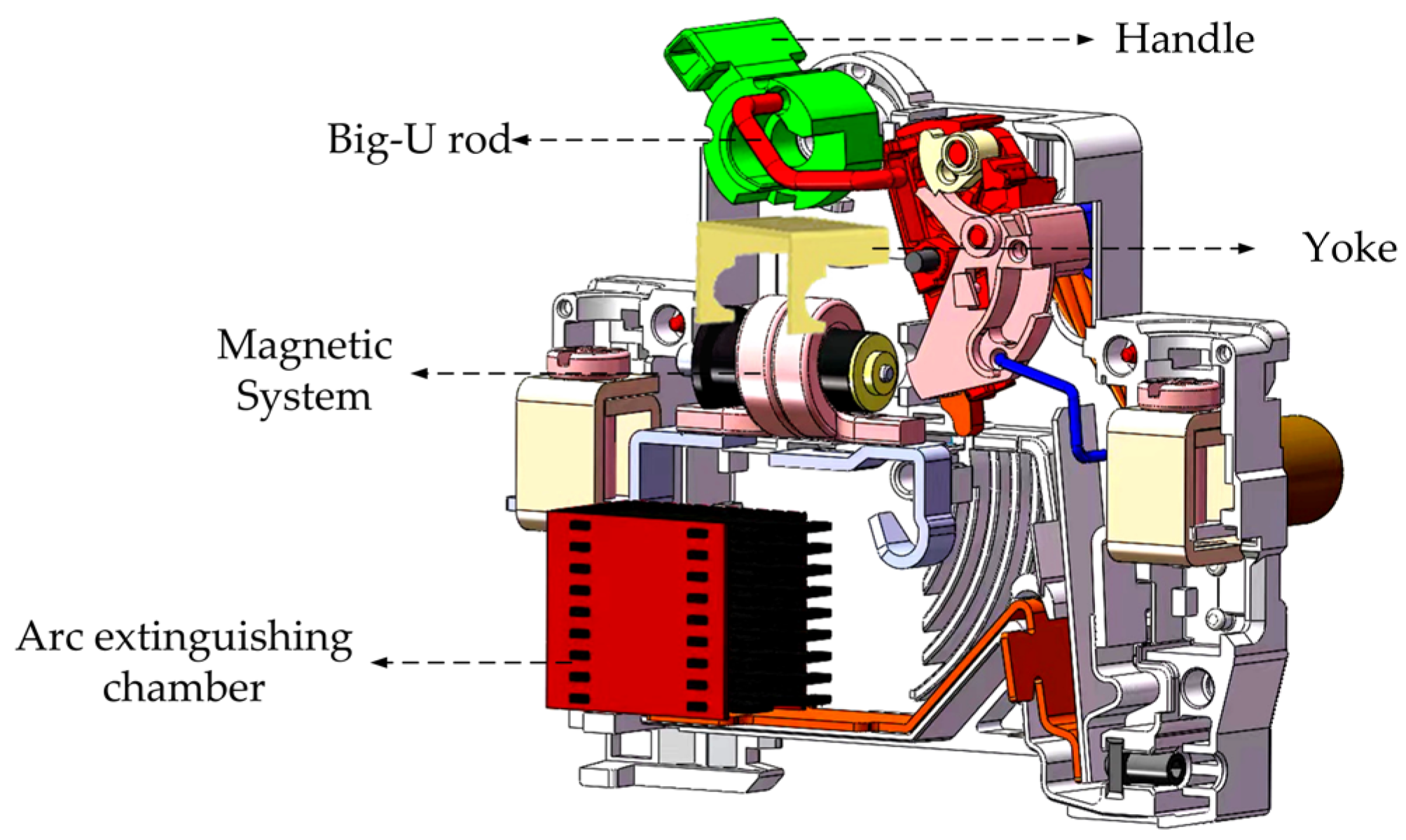
2.1. Problems and Optimization in CBs Manufacturing

2.1.1. Problems with Traditional Semi-Automated Manufacturing Lines

In Figure 2, the traditional semi-automatic CBs manufacturing line is connected with different manufacturing sub-units. A series-parallel operation for manufacturing is used in the production line, connected by shunting and merging equipment. Unit 1 and units 7–13 of the line are serial units. During the serial manufacturing process, the carrier sources are automatically assembled in each sub-unit by a conveyor belt. Units 2–6 are parallel. The carrier sources are shunted from units 1 to units 2–6 to complete the manual manufacturing of the parts. From the overall layout, its manufacturing process involves the separate manufacturing of each part. Problems such as the long and heavy structure of the production line will be caused by this method. There is still manual work in the production line, which is bound to result in low manufacturing efficiency, poor reliability, and other problems.

2.1.2. Problems in Single-Robot Flexible Manufacturing System

In Figure 3a, posture adjustment is a crucial unit in multi-robot collaborative CBFMS, which completes the part’s attitude adjustment through the cooperation of the robot and the auxiliary mechanism. In Figure 3b, when the auxiliary adjustment mechanism performs posture adjustment, it needs to adjust the part’s attitude to the manufacturing requirements through the joint angle rotation of the robot. After the correction, the parts are picked up from the auxiliary machinery and assembled onto the part sorting carrier. With all parts needing to be adjusted, the above operation will undoubtedly increase the manufacturing time. When one of the production units takes more time, the entire production rhythm of the system will be affected. Finally, it will lead to production stagnation and inefficiency.

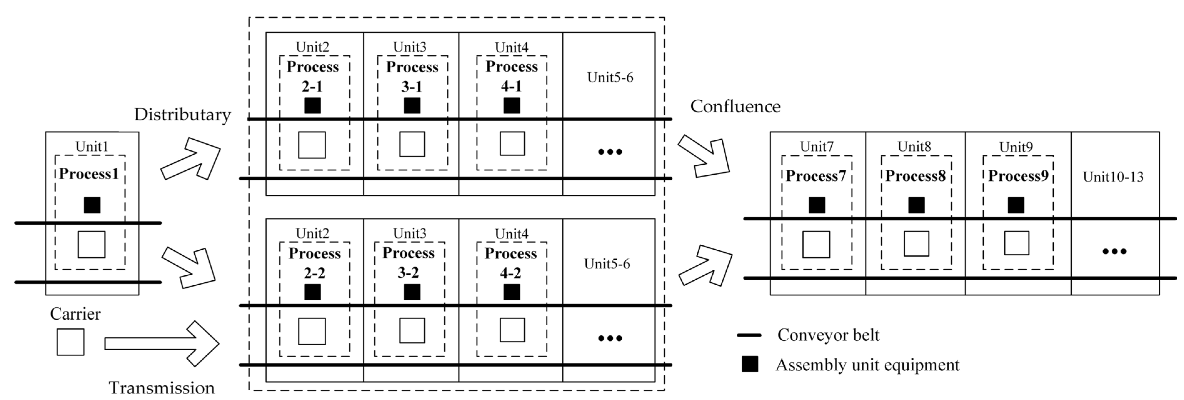
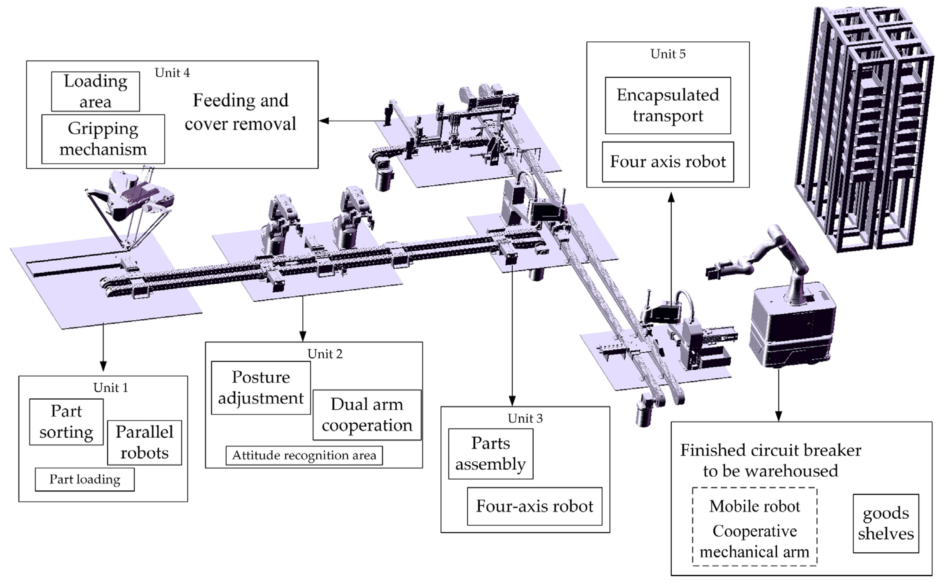
2.2. Multi-Robot Collaborative CBs Flexible Manufacturing System

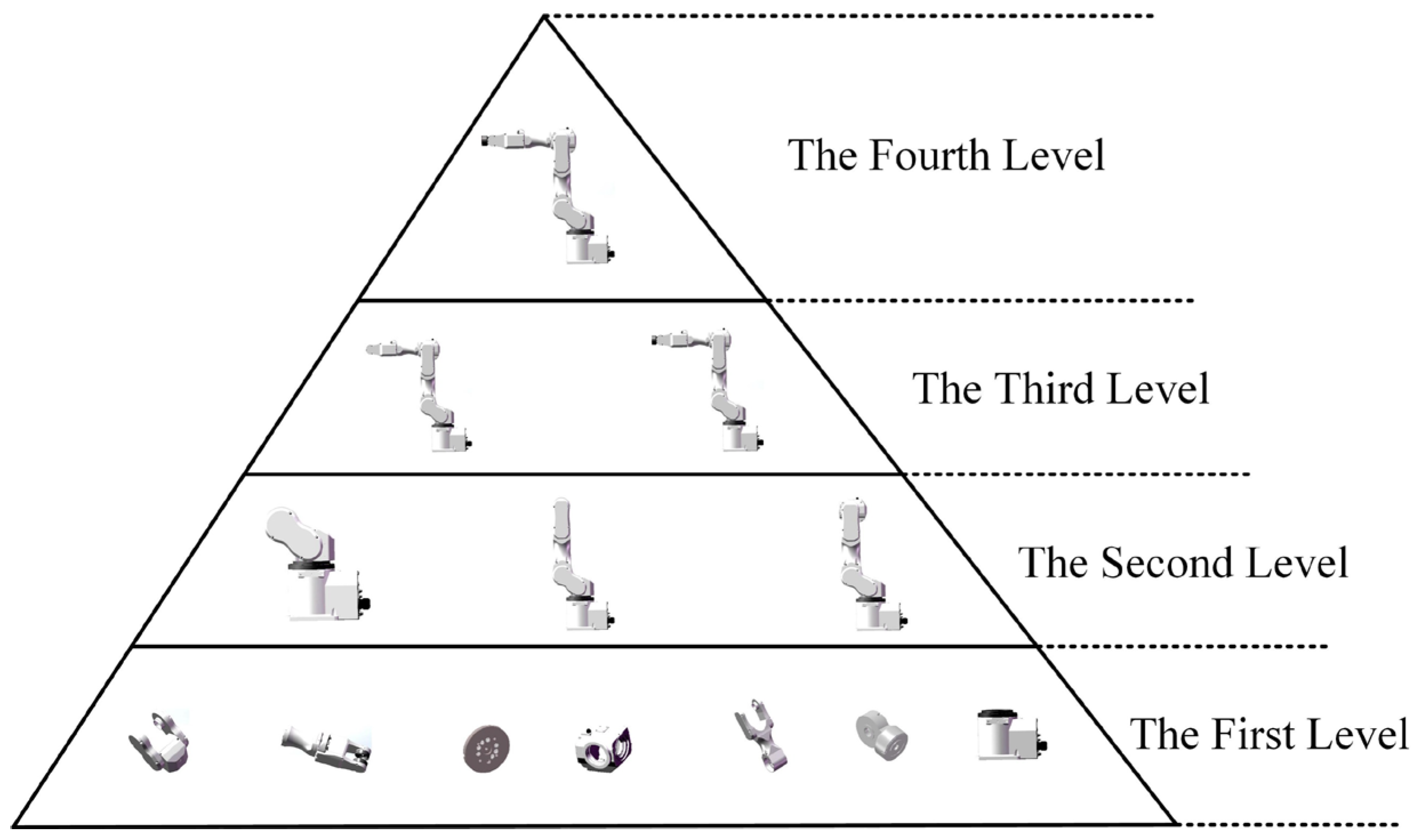
Multi-Robot System Construction and Task Distribution

To solve the problems of the existing technical solutions, a multi-robot collaborative CBFMS is designed and optimized in this paper. The system consists of multi-robot units, which assign different tasks according to robot characteristics. The system structure is shown in Figure 4.
The system functions are described as follows. Unit 1 is a parts sorting unit, including a parallel robot, a parts transport track, a return unit, and a part sorting carrier. The six types of CBs parts required for manufacturing are picked out by the parallel robot combined with the vision algorithm. Unit 2 is a position adjustment unit, including a collaborative robot arm, a main robot arm, a position adjustment carrier, and an end-effector. To adapt to the posture required for manufacturing, the six randomly positioned CB components are adjusted by the cooperation of the robots. Unit 3 is the manufacturing unit, including a four-axis robot and a flexible gripper. Its function is the automatic assembly of the parts into monoblack CBs at the specified position. Unit 4 is the loading and splitting unit, including a loading device and a splitting device. Its function is to automatically feed and split the CBs for subsequent automatic manufacturing of parts. Unit 5 is a package and storage unit, including a four-axis robot and flexible clamping jaws. Its function is to package the assembled CBs. Unit 6 is the storage unit, including a mobile robot and shelves. The mobile robot includes a mobile chassis and a collaborative robot arm. The function of the unit is to load raw materials and store the finished CBs.

2.3. Improvement of Key Assembly Unit Scheme

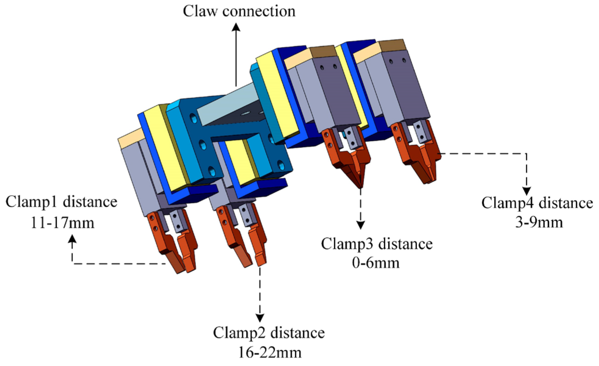
2.3.1. Flexible Multi-Gripper Claw Design

Traditional semi-automatic production cannot achieve accurate clamping because of the different specifications of each part. To achieve flexible production, a flexible multi-gripper claw is designed in this paper, as shown in Figure 5. According to different part sizes and assembly requirements, four grippers with different strokes are designed in the mechanism to ensure the fit of the clamping range and positioning accuracy. The flexible multi-gripper claw is connected to the robot’s end-effector through a claw connection. In the assembly process, the robot combines the visual camera to select the appropriate gripper for grasping.

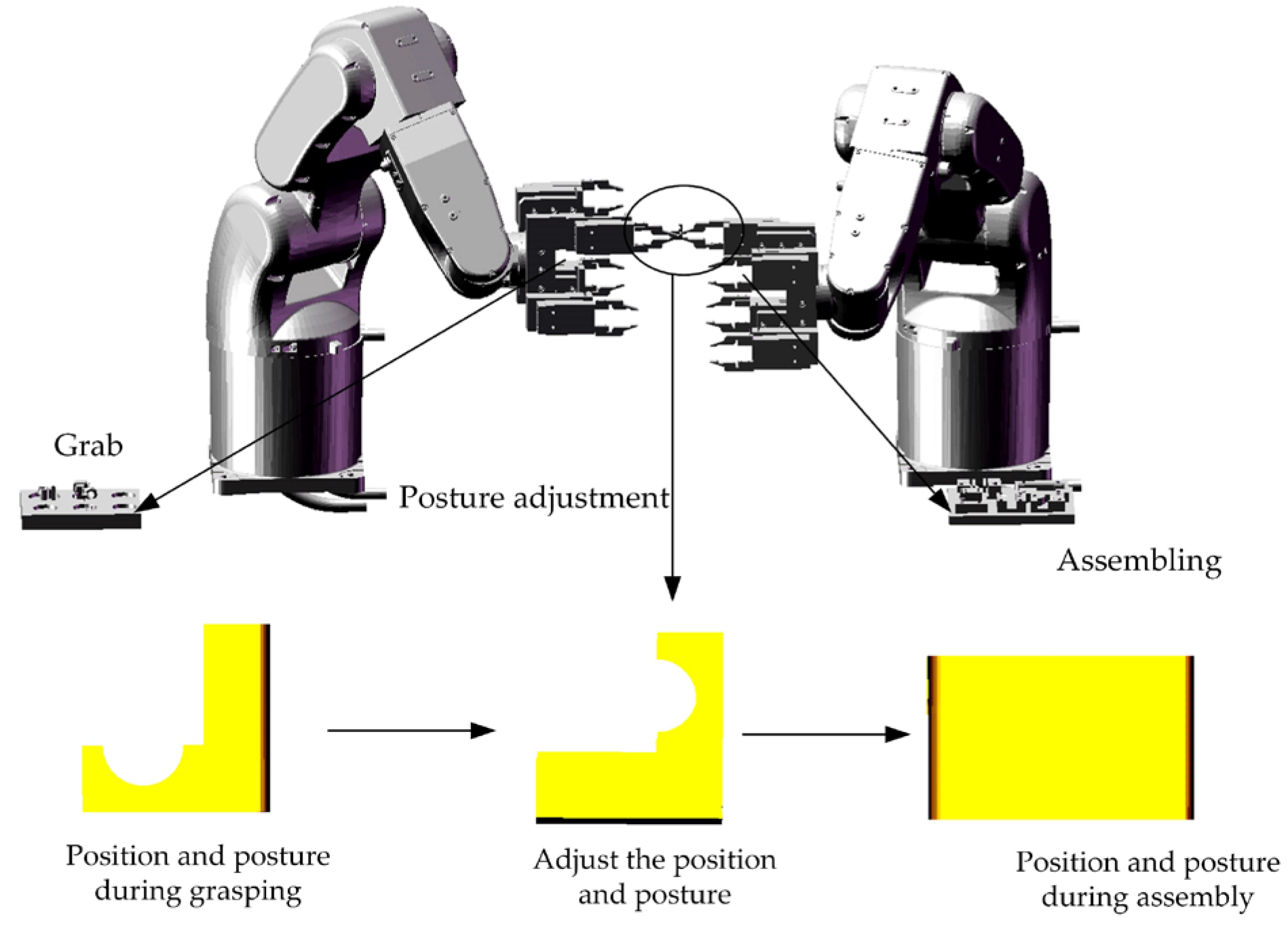
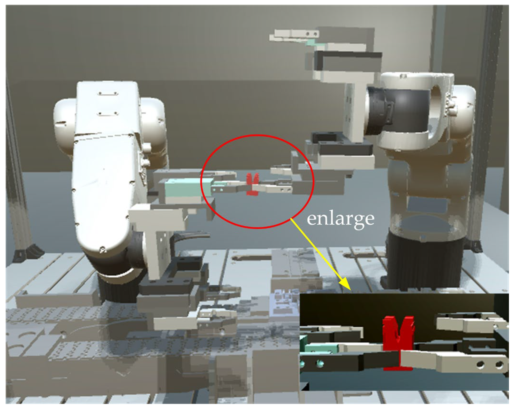
2.3.2. The Assembly of Two-Arm Cooperation Robot

The parts’ posture adjustment is the most important unit in multi-robot collaborative CBFMS. The existing method in posture adjustment relies on a single-robot system, and the improvement of production efficiency and capacity is restricted. To improve the efficiency of posture adjustment, a two-arm cooperation robot method is designed in this paper, as shown in Figure 6. According to the current state of the parts, the cooperative robot arm selects the appropriate gripper to clamp the parts. After the cooperative robot arm rotates the parts to be adjusted to the state required for cooperation, the main robot arm rotates the end actuator to the corresponding angle for grasping. When the main robot arm completes grasping, the parts with the required posture are placed in the carrier. The operation allows simultaneous gripping, adjustment, and manufacturing, which can greatly improve work efficiency.

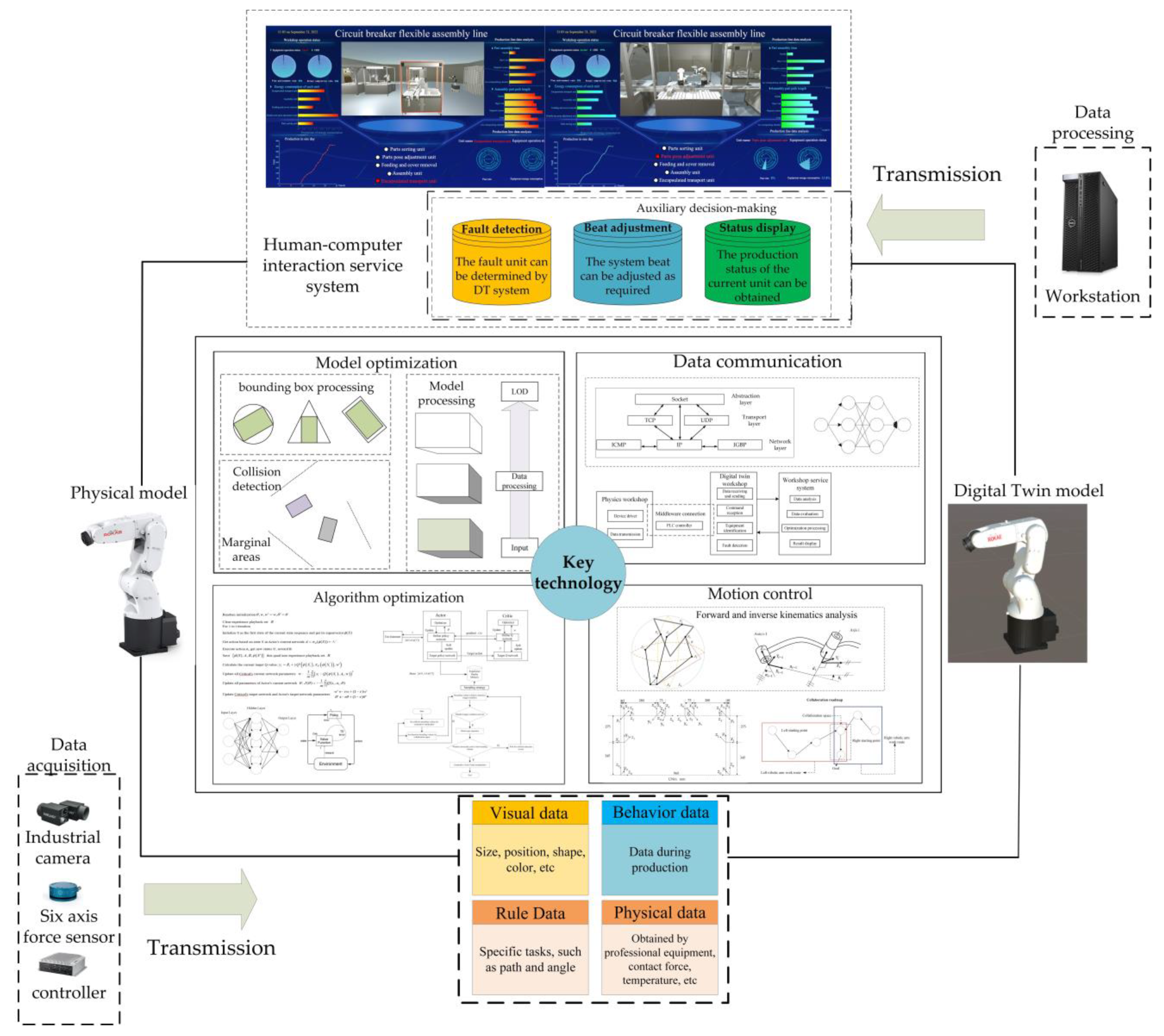
2.4. DT Framework of the Multi-Robot Cooperative CBFMS

The four major components of the DT include the physical entities, DT models, data processing, and visualization services [30]. The flexible manufacturing DT framework is summarized as follows:
  • Physical entities: The physical entities mainly include physical components, such as multi-robots, conveyors, parts, and boxes, as well as functional components, such as controllers, sensors, and the programmable logic controller (PLC).
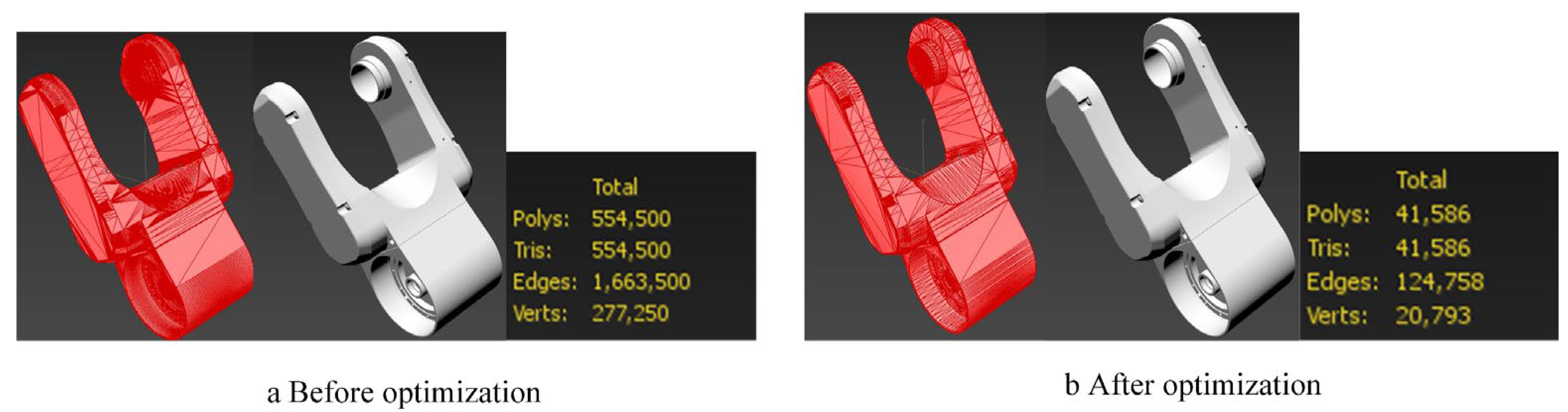
  • Twin model: As a prerequisite for the DT system, the construction and processing of the twin model are extremely important. A highly reductive twin model can reduce the pressure when building the DT system [31].
  • Data processing: As a critical part of the twin system, the virtual layer is connected with the physical layer through data processing. The data generated by the physical layer are read and processed by data reading devices and finally sent to the twin system. Stable, efficient, and secure data transmission is a prerequisite for real-time interaction.
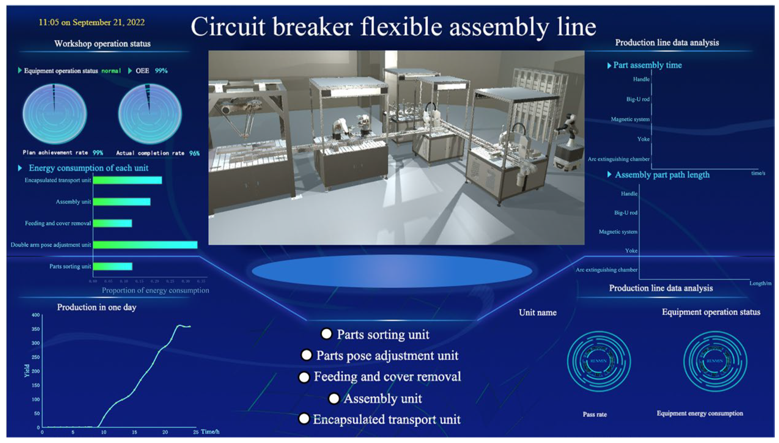
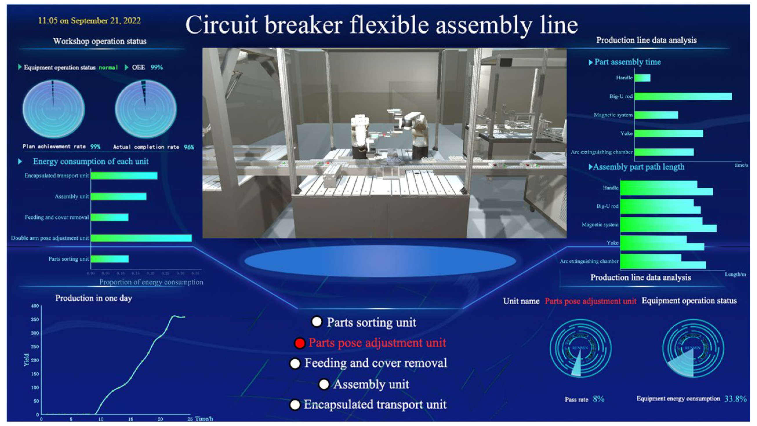
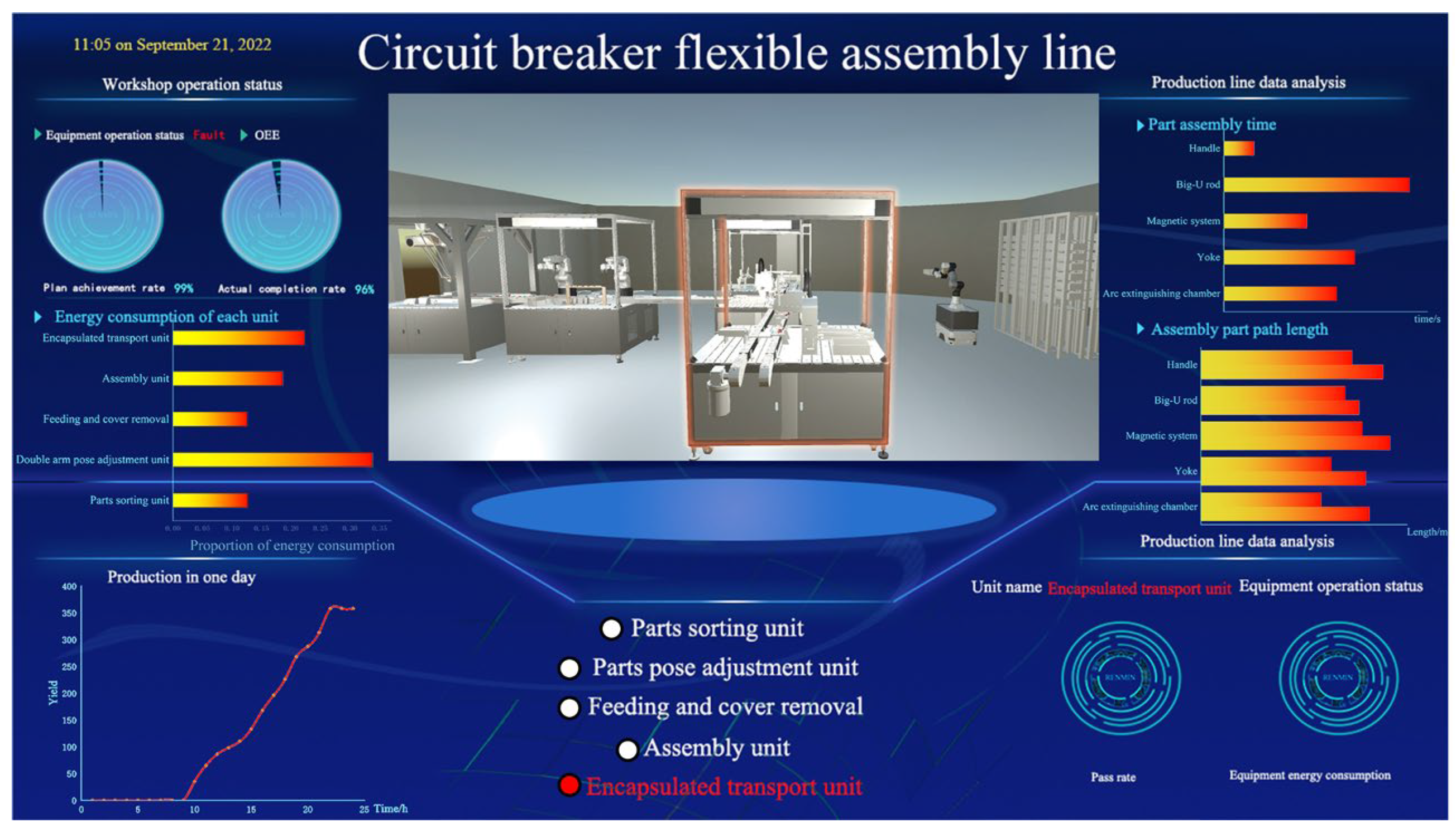
  • Visualization services: Real-time mapping of the entities’ actions, behaviors, and states is the basis of DT technology [32]. Through the real-time monitoring of the DT system, the essential services in the workshop are displayed through visualization services.
As can be seen in Figure 7, data are acquired from the physical robot model through industrial cameras and force sensors. Data types include visual data, physical data, and production data. The data generated by the robot are processed and transmitted through a communication system between the physical and virtual units. The processed data are displayed through a visualization service system, and the user can observe the system’s state and detect faults promptly. In Figure 7, the critical technologies required to construct the flexible manufacturing DT system are illustrated in this study, including the processing of the model, kinematic control algorithms, data acquisition and processing, and visualization services. The feedback mechanism of the system framework is as follows. Firstly, physical unit data are obtained from external devices, and the virtual model is assigned the attributes of physical entities. Secondly, data are transferred to the workstation; then, data are processed by the workstation to build a digital twin system, including algorithm optimization, robot kinematics control, model data optimization, and so on. Finally, data transmission in the DT system is operated by the data communication mechanism to the DT system visualization service.

3. The Control Strategy of Two-Arm Cooperation Robot

To improve the flexible manufacturing efficiency, a two-arm cooperation robot flexible automatic assembly method is proposed in this study. The collaborative robots need to assemble the parts with high accuracy and no collision during the assembly process. To complete the cooperative assembly task better, it is necessary to control the kinematics of the cooperative robots. Simultaneously, to reduce redundant paths during the manufacturing of collaborative robots, the assembly trajectory of the robot arms needs to be optimized.

3.1. Kinematic Control of Two-Arm Cooperation Robot

The robot used in this paper is the ROKAE XB-4 robot arm, and its D-H coordinate system is established, as shown in Figure 8. The D-H parameters of the two-arm cooperation robot are shown in Table 1, which include the rotation angle, the joint offset, the connecting rod length, and the torque. Similarly, the D-H parameters of the collaborative robot arm are the same.

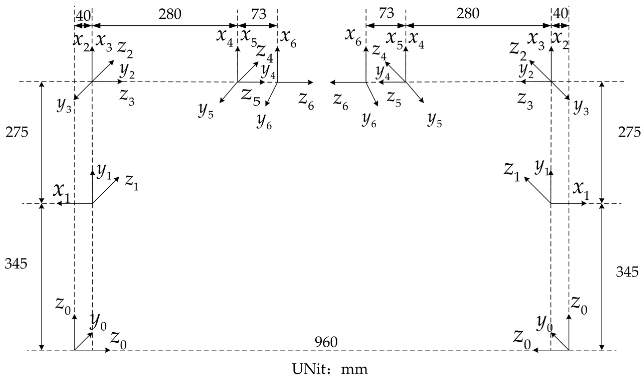
3.1.1. Forward Kinematics Analysis of the Two-Arm Cooperation Robot

On the robot arm base, the homogeneous transformation can be carried out sequentially from the first joint to the end joint of the robot arm. The homogeneous transformation matrix between adjacent linkage coordinate systems can be described as
R θ i = cos θ i sin θ i 0 0 sin θ i cos θ i 0 0 0 0 1 0 0 0 0 1 D d i = 1 0 0 0 0 1 0 0 0 0 0 d i 0 0 0 1 D a i = 1 0 0 a i 0 1 0 0 0 0 0 0 0 0 0 1 R α i = 1 0 0 0 0 cos α i sin α i 0 0 sin α i cos α i 0 0 0 0 1
The real transformation relationship between the base and the end of the robot arm can be obtained by multiplying these transformation matrices. According to the steps for establishing the linkage coordinate system, the coordinate linkage coordinate system i can be described in the coordinate system i 1
T i i 1 = R ( α i 1 ) D ( α i 1 ) R ( θ i ) D ( d i ) = cos θ i sin θ i 0 α i 1 sin θ i cos α i 1 cos θ i cos α i 1 sin α i 1 sin α i 1 d i sin θ i sin α i 1 cos θ i sin α i 1 cos α i 1 cos α i 1 d i 0 0 0 1
The transformation matrix is used to transform a vector defined in the coordinate system i into a description in the coordinate system i 1 , which can be defined as
n 0 T = 1 0 T 2 1 T n n - 1 T
For the six-axis robot arm in this paper, the total transformation from the base to the end of the actuator can be written as
T 0 6 = T 1 0 T 2 1 T 3 2 T 4 3 T 5 4 T 6 5

3.1.2. Inverse Kinematics Analysis of the Two-Arm Cooperation Robot

Based on the transformation relationship shown in Equation (3), the right matrix of the equation is inversely multiplied to the left of the equation. The joint angle of the manipulator can be inversely deduced from the Cartesian coordinates of the manipulator’s end. Finally, the inverse solution of the joint of the robot arm can be written as
T 1 0 1 T n 0 = T 2 1 T n 1 n 2 T n n 1
In this study, the equation conversion from the end-effector to the robot arm joint can be described as
T 6 5 1 T 6 0 = T 1 0 T 2 1 T 3 2 T 4 3 T 5 4 T 5 4 1 T 6 5 1 T 6 0 = T 1 0 T 2 1 T 3 2 T 4 3 T 4 3 1 T 5 4 1 T 6 5 1 T 6 0 = T 1 0 T 2 1 T 3 2 T 4 3 1 T 4 3 1 T 5 4 1 T 6 5 1 T 6 0 = T 1 0 T 2 1 T 2 1 1 T 4 3 1 T 4 3 1 T 5 4 1 T 6 5 1 T 6 0 = T 1 0
where n n - 1 T represents the transformation matrix between adjacent connecting rods.

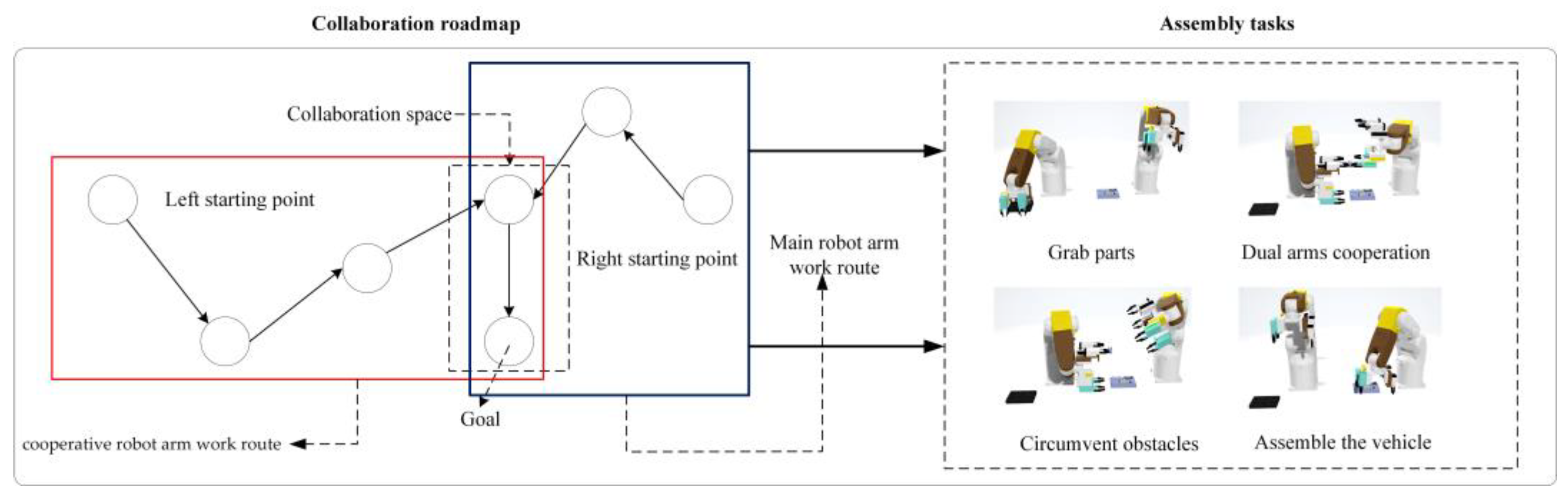
3.2. Cooperative Space Analysis of the Two-Arm Cooperation Robot

The efficiency and safety of the system are restricted by the operability of cooperative robots. This is a crucial issue in multi-robot collaboration. Spatial maneuverability can be translated into the process of spatially fitting the two-arm cooperation robot, which can be written as
x x 1 2 a 1 2 + y y 1 2 b 1 2 + z z 1 2 c 1 2 1 x x 2 2 a 2 2 + y y 2 2 b 2 2 + z z 2 2 c 2 2 1
where a, b, and c represent the polar radii of the ellipsoid; and x 1 , x 2 , y 1 , y 2 , and z 1 , z 2 represent the coordinates of the center points of the trajectories of the two-arm cooperation robot. There is a certain coordination relationship when the two-arm cooperation robots are assembled. The motion state of the two-arm cooperation robot can be described as
X = J ( q ) Q
where X = x 1 x 2 , Q = q 1 , q 2 T , J q are the Jacobi matrices of the two-arm cooperation robot with values of
J q = J ( q ) 1 0 0 J ( q ) 2
Respectively, J ( q ) 1 , J ( q ) 2 are the Jacobi matrices of the two-arm cooperation robot. Thus, the spatial maneuverability M of the two-arm cooperation robot is
M = det ( J ( q ) 1 J q ) 1 T det ( J ( q ) 2 J q ) 2 T
The robot model is created in Matlab based on the D-H parameters. The Monte Carlo method is used to construct the executable space of the two-arm cooperation robot through a point cloud plot. The more points used in the experiment, the higher the accuracy of the results. Twenty thousand sampling points are used to sample its spatial distribution; the result is shown in Figure 9. It can be seen that the collaboration space between the two-arm cooperation robots ranges from 0 to 200 mm; the end-effector gripper length ranges from 60 mm to 70 mm; and the size of the six CBs parts ranges from 7 mm to 12 mm. It can be concluded that all the assembled parts’ processes exist within the collaboration space, and the feasibility of the solution provides a guarantee for the parts grasped by the two-arm cooperation robot.

3.3. Trajectory Optimization of the Two-Arm Cooperation Robot

To adjust the random posture of the CBs parts, the two-arm cooperation robot must go through the process of grasping, obstacle avoidance, cooperation, and manufacturing. There are three critical points in these four processes, as shown in Figure 10: one is the point position when the cooperative robot arm is grasping the parts; the other is the point position when cooperative robots cooperate with each other; the last point is the point position when the parts are assembled. The robot arms need to reach the critical point before performing relevant operations. Specifically, the collaborative robot arm needs to rotate the end-effector to the collaborative working state after grasping the part. At the same time, the main robot arm cooperates in grasping the part and then puts the part into the carrier with the required posture. During the process, the robot needs to take the shortest path to the critical point within the limits of the joint angle. Collaborative robot arms must not collide with each other or with obstacles such as part carriers during their movement. To optimize the trajectory when the cooperative robots assemble the parts, a reinforcement learning approach is used. Based on the part manufacturing environment, the robots learn to make optimal action decisions to complete the task in the context of assembling different parts.
Traditional control algorithms for robot arms tend to result in redundant paths, long response times, and low accuracy in reaching the target. To optimize the trajectory during assembly, deep reinforcement learning is used to train the two-arm cooperation robot. According to the current action state, the strategy is adjusted by the two-arm cooperation robot, and action is executed in a new manufacturing state. Furthermore, the value of the manufacturing behavior is calculated by setting the reward and punishment function. Finally, it will be fed back to the two-arm cooperation robot. According to the current part posture state, the robot adjusts the strategy and executes the action in the new manufacturing state. These samples are used by the reinforcement learning algorithm to optimize the robot’s trajectory and improve the robot’s action strategy in the CBs manufacturing environment. After continuous iterative learning, the optimal trajectory is obtained by the two-arm cooperation robot to adjust the parts’ posture.

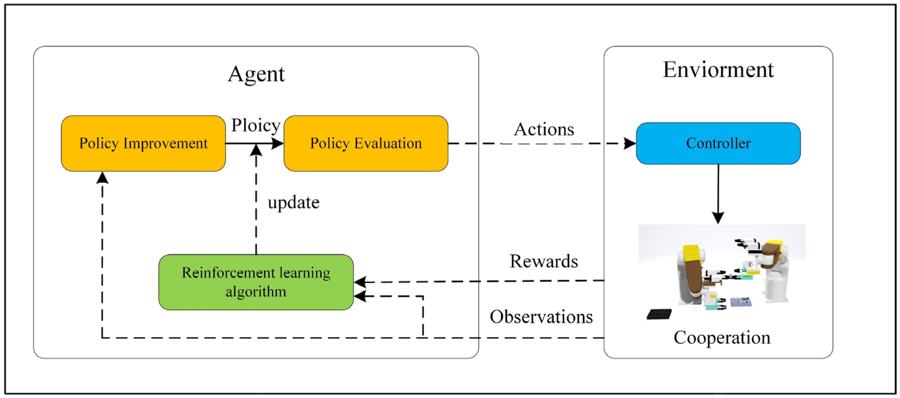
3.3.1. Reinforcement Learning

The approach to reinforcement learning can be described as a Markovian decision process (MDP). The MDP can be summarized by S A P R γ , where S is a finite set of states, s is the next state, A is a finite set of actions, and P is the probability of a state transfer. P ( S t + 1 = s | S t = s , A t = a ) is defined to represent the probability of an action a transferring to a state s under state s. R is the reward function, which can be expressed as R = E ( s t , a t ) . γ is the discount factor, which is the proportion of the value of a future reward at this moment. The MDP can be described as the action state value function and the state value function. The action value function is the process by which S uses strategy π to find the maximum reward expectation under action a, which can be defined as
q π ( s ) = E π ( G t | s t , a t )
The state value function is the expectation obtained according to the state s, defined as
v π ( s ) = E π G t | S t = s
where G t is the discount incentive, which is defined as
G t = R t + 1 + γ R t + 2 + = k = 0 γ k R t + k + 1
where R t is the reward value at each moment.
The optimal state value function and the maximum action value function are defined, respectively, as
v * s = max π v π s q * = max π q π s , a
where v π ( s ) , q π ( s , a ) are the state value function.
The advantage of reinforcement learning over machine learning is the ability to constantly interact with the environment at all times and to constantly receive rewards. The agent actions are taken with the goal of maximizing cumulative rewards; the mechanism is shown in Figure 11.

3.3.2. Reward and Punishment Mechanism Setting

The evaluation of behavior is an important part of deep reinforcement learning training. When appropriate reward mechanisms are set up, it can improve training speed and improve algorithm performance. To address the sparse reward problem, an artificial potential field method for setting the reward mechanism is used in this paper. The robot arm is rewarded when it is close to the target and punished when it is far from the target. Similarly, when the end-effector of the robot arm is close to another end-effector, it is penalized. The basic model is
D s = x s 1 x s 2 2 + y s 1 y s 2 2 + z s 1 z s 2 2 D min = D s 0 ( i = 0 ) min D s i , D s i , D min ( i 0 ) R = D min D s t k 1 D min > D s t D s t D min k 2 D min < D s t k 3 D s t = 0
where D is the distance between the end-effector of the robot and the key point, which varies with time. D min is the minimum distance, and R is the reward value. When the distance D s is less than the minimum distance, the arm moves closer to the target key point and receives a reward k 2 . When the distance D s is greater than the minimum distance, the arm moves away from the target key point and receives a penalty k 1 . When the robot reaches the key point accurately, the maximum reward k 3 is given (k is a constant). The robot arm continuously updates R in Equation (14) during each training session. According to the distance between its own position and the key point, it continuously approaches the target key point and finally maximizes the accumulated reward for the target action. When the training is completed, the robot arm can reach the target point directly at this point, avoiding redundant paths during manufacturing and achieving the effect of path optimization.

3.3.3. The Deep Deterministic Policy Gradient (DDPG) Algorithm

Compared with traditional machine-learning algorithms, the DDPG algorithm allows model-free offline training and can move continuously. It is simple and efficient for the environment created in this paper. The DDPG algorithm is implemented in the Actor–Critic framework; the schematic is shown in Figure 12.
The network used in the DDPG algorithm is the Actor–Critic network. The Actor network is a neural network that approximates the policy function, which is divided into the online policy network and the target policy network. The Critic network is a neural network that approximates the value function, which is divided into the Critic online Q network and the target Q network. According to the Actor network, the online policy network sends the behavior A selected and executed by the intelligent body at time t, which can be written as
A = μ s t | θ
where s t is the state data of the environment observed by the intelligent body, and θ is the Actor’s online policy network parameter.
The robot model outputs a new reward value and environment state after execution and uses random sampling data as training data. The estimated action value Q of the Critic target network is calculated by combining the training data with the Actor target strategy network and the Critic target Q network. According to the mean square error loss function, the Critic online network parameters are updated to calculate the policy gradient of the Actor online policy network and to update the Actor online policy network parameters. The DDPG algorithm updates the Critic network parameters by minimizing the loss function L, which can be written as
L = 1 M i y i Q s i , a i | w 2
where w is the Critic’s network parameter, and y i is the value of the current target Q network. The value is
y i = R i + γ Q s i + 1 , μ s i + 1 | θ | w
The gradient descent method is used to determine the direction of iterative descent of parameters in the learning process by calculating its partial derivative. The gradient descent method updates the Actor network parameters, and the specific formula can be written as
θ J 1 M i a Q s , a | w s = s i , a = μ s i θ μ s | θ s i
where a Q is the evaluation gradient; θ μ is the action gradient.
Finally, the Actor’s target strategy network and the Critic’s target Q network are soft updated. The parameter update process can be written as
w τ w + ( 1 τ ) w θ τ θ + ( 1 τ ) θ
where θ is the target policy network parameter; w is the target Q network parameter; θ is the online policy parameter; w is the online network parameter. The DDPG algorithm code is written in this framework, and the pseudo-code is shown in Algorithm 1.
Algorithm 1: DDPG algorithm pseudo-code.
Random initialization θ , w , w = w , θ = θ
Clear experience playback set R
For 1 to t iteration
Initialize S as the first state of the current state sequence and obtain its eigenvector ϕ ( S )
Get action based on state S in Actor’s current network A = μ s t | θ
Execute action a t , obtain new status s t + 1 , reward r t
Save s t , a t , r t , s t + 1 this quad into experience playback set R
Calculate the current target Q value: y i = r i + γ Q s i + 1 , μ s i + 1 | θ | w
Use loss function to update Critic’s network parameter: L = 1 M i y i Q s i , a i w 2
Update Actor’s parameters: θ J 1 M i a Q s , a w s = s i , a = μ s i θ μ s θ s i
Update Critic’s and Actor’s target network parameters: w τ w + ( 1 τ ) w θ τ θ + ( 1 τ ) θ
End for
End for

3.4. Simulation Experiments

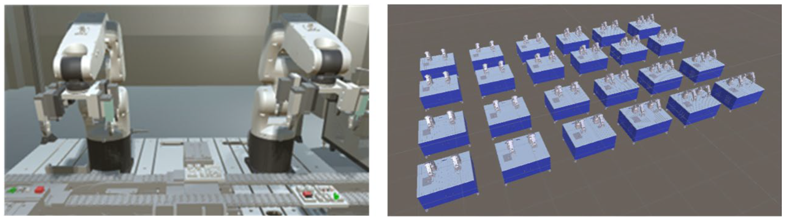
3.4.1. Experimental Environment

The process of reinforcement learning requires numerous errors to be experienced. However, robots have a joint limitation and a safety issue in a real environment, so the robot is trained in a virtual environment for reinforcement learning in this paper. Robots are trained in the Unity environment, as shown in Figure 13. Multiple robots can be trained simultaneously sharing the same trained data at high speeds, cutting down training time.

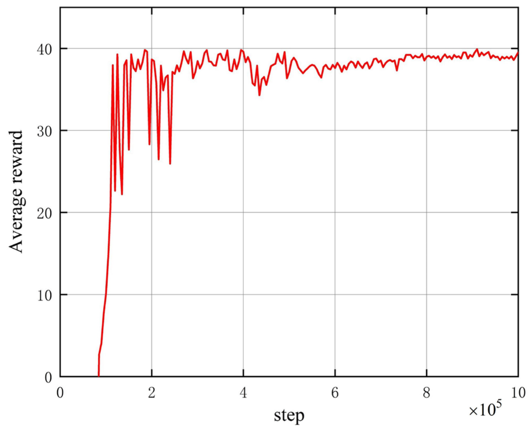
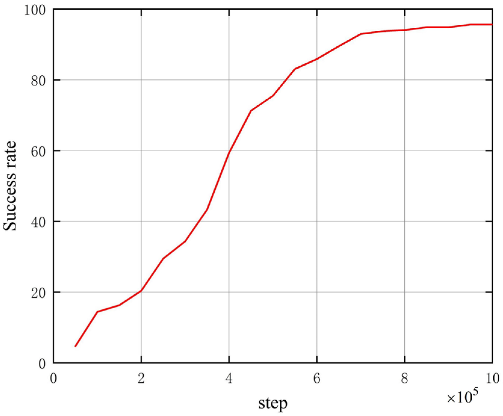
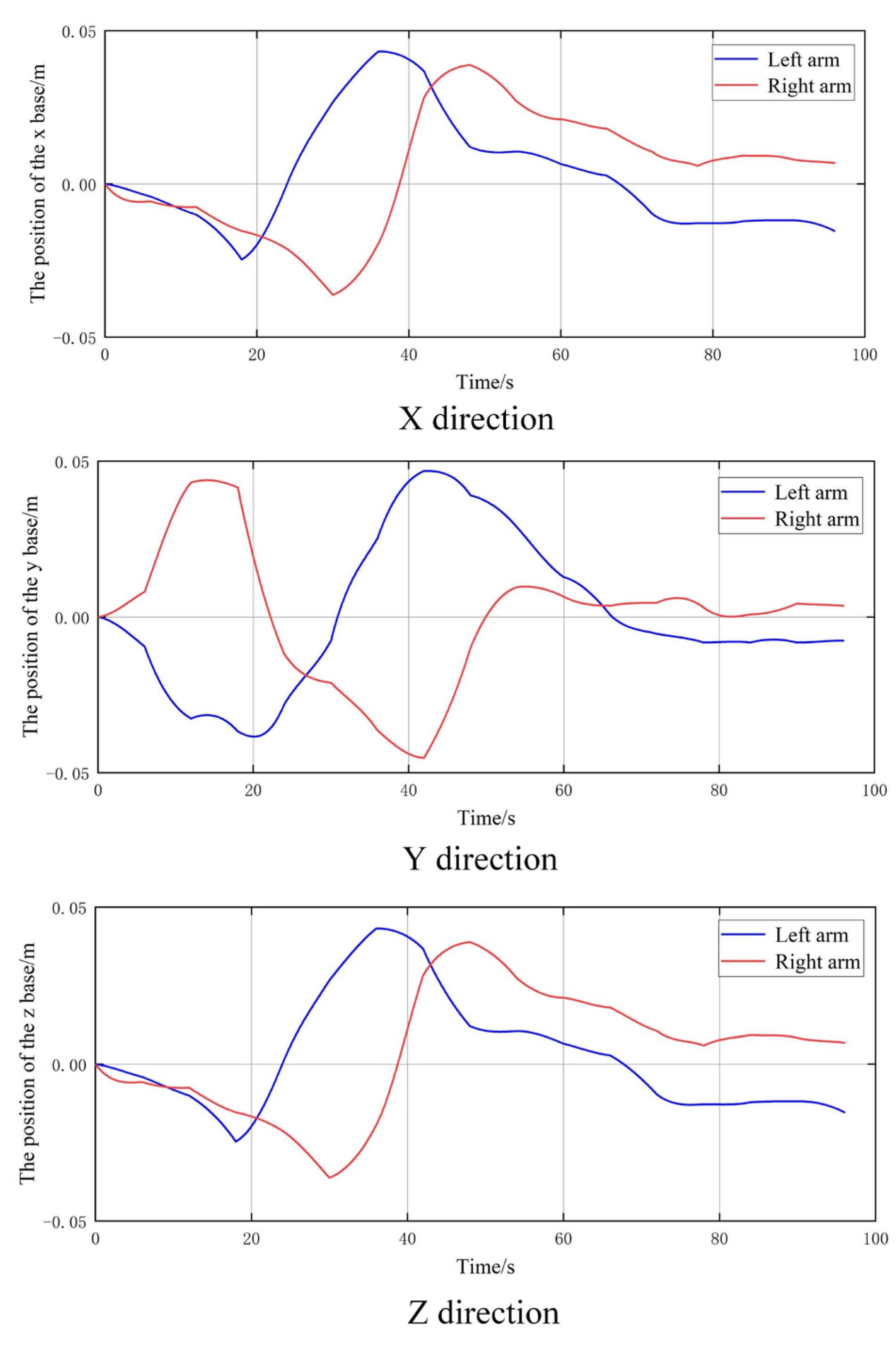
3.4.2. Simulation Experiments’ Results

In the experiment, the maximum number of training steps was set to 1 million. During the training process, the round ended immediately when the robot reached the target point, collided with an obstacle, exceeded the preset working range, or failed to reach the target point for a long time. Finally, the average reward at convergence was calculated.
As can be seen in Figure 14, the reward obtained by the agent robot gradually increases, reaching a state of convergence at nearly 5 × 10 5 steps. The robot can mostly avoid obstacles to reach the target point of the collaborative manufacturing interrupter chamber within a short period of time. It is concluded that its chosen action can achieve better planning results and steadily control the robot arm to reach the target point. To test the success rate of reaching the target point, the following graph shows the success rate of the two arms reaching the key point of adjusting the interrupter chamber.
As can be seen in Figure 15, the success rate of the two-arm cooperation robot at reaching the collaborative key point is increasing. The result proves that it has good stability for the collaborative manufacturing parts, and the success rate converges to about 96% when the number of steps is about times. It is a high success rate for the two-arm cooperation robot to reach the target point, proving that the algorithm can make the two-arm cooperation robot reach the target point accurately. After the training, the part grabbing test is carried out using the training result model, and the result is shown in Figure 16.
As can be seen in Figure 16, the two-arm cooperation robot can eventually grasp the part successfully with no collision. It is proven that the algorithm is effective in commanding the two-arm cooperation robot to assemble parts. The robot will have a certain error relative to the ideal point position during the experiment. To verify whether the error present will affect the grasping, the error between it and the ideal point position is judged by observing the trajectory of the robot arm movement. The deviation curve of the trajectory variation of the two-arm cooperation robot over time is shown in Figure 17, which represents the deviation of the two-arm cooperation robot from the ideal target position in the x, y, and z directions.
As can be seen in Figure 17, the deviation in the x direction is eventually controlled between −0.22 m and −0.13 m; the deviation in the y direction is eventually controlled between −0.05 m and −0.02 m; and the deviation in the z direction is eventually controlled between −0.15 m and −0.09 m as the time changes. The deviations in the x, y, and z directions are eventually within the manipulable range of the part manufacturing. The feasibility of the two-arm cooperation robot cooperation scheme is proved in this paper. To verify the effectiveness of the optimized method, the traditional method was compared with the method in this study. By comparing the time and success rate of grasping five parts, the results are shown in Table 2.
For the arc extinguishing chamber part, compared with the traditional method, the optimized method assembly time is decreased by 2.88 s, the efficiency is increased by 44.17%, and the assembly accuracy is increased by 3.1%. For the magnetic system, the optimized method assembly time is decreased by 6.71 s, the efficiency is increased by 63.48%, and the assembly accuracy is increased by 3.6%. For the yoke part, the optimized method assembly time is decreased by 1.36 s, the efficiency is increased by 23.09%, and the assembly accuracy is increased by 2.2%. For the big-U rod part, the optimized method assembly time is decreased by 4.09 s, the efficiency is increased by 55.57%, and the assembly accuracy is increased by 0.5%. For the handle part, the optimized method assembly time is decreased by 2.65 s, the efficiency is increased by 50.28%, and the assembly accuracy is increased by 2.7%. Based on the experimental results, it can be concluded that the method proposed in this paper can greatly reduce the manufacturing time of the five parts. The manufacturing efficiency is improved, and the problem of the unit with a poor production beat is solved.

4. Design of a DT System for Multi-Robot Cooperative CBFMS

4.1. Construction and Optimization of the Robot Model

DT models are classified into static and dynamic in this paper because the composition is extremely complex. The classification normalization process is adopted in this study; models with the same attributes and logic as higher level models are linked using a function.
Let us take a six-degree-of-freedom robot arm as an example. To comply with the motion constraints of the robot, the subordination of the logical model needs to be established. With the pedestal of the robot as the base, the parent function is used to build the subordination from the bottom up. The first level is the child level, and the higher level is the parent level. By calling the link function, when the joints of the parent level move, the joints of the child level can also move with them. The hierarchy is constructed, as shown in Figure 18.
Optimization of the model is a prerequisite for DT. With the volume of data increasing in the later stages of the process, if the number of points and faces in the model is too large, the memory consumption will have a burden, and the rate of operation will be affected. The basic premise of optimization is to make the number of faces and points of the model as small as possible without affecting the appearance of the model. The traditional levels of detail algorithm optimizes the model by layering the model and retaining the highest level of the model. This method does not provide sufficient model granularity when processing the model, and the finished model is still relatively crude and poorly smoothed. Therefore, an adaptive weight reduction to handle the model is used in this paper. It can reduce the number of points and surfaces of the model according to the weight size, and the model can be finely optimized. The model can be optimized while maintaining its smoothness of the model. The formula for the adaptive weight reduction method can be defined as
ω = i = 0 n P i n i = 0 n P i W = k W × ω · n + 1 k W × 1 max ( l 1 , l 2 , l 3 ) l 1 + l 2 + l 3
k W = k W W max W min + 1
where P i is the area of the triangle; n is the normal vector of the triangle; l 1 , l 2 , l 3 is the length of the three sides of the triangle; W is the weight size; k W is the dynamic weight; k is the base weight size, assuming the values [0, 1].
After the calculation according to Equation (21), the triangles with larger weights are deleted, and the weights are recalculated according to Equation (22) after completion.
The following is an example of a joint of a six-degree-of-freedom robot arm, which was optimized using this algorithm, and the test results are shown in Figure 19.
The result of the comparison shows that the number of points and surfaces of the model is greatly reduced without changing the shape and effect of the model, and the optimization efficiency is increased by 92.51%. This proves the effectiveness of the algorithm.

4.2. DT Model Behavioral Relationship Construction

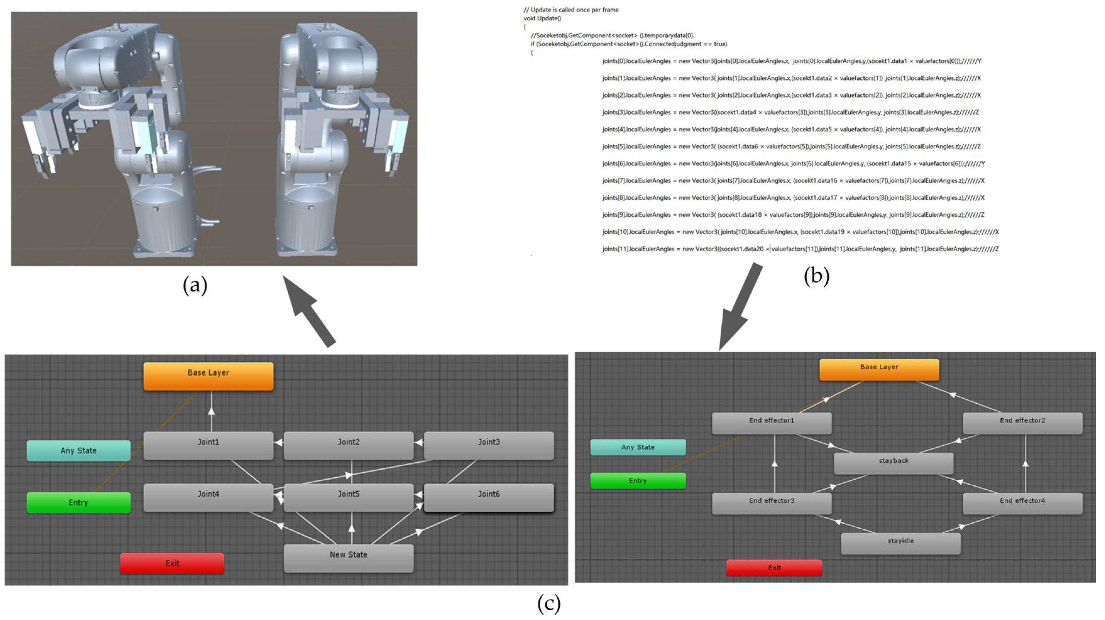
4.2.1. The Robot DT Models’ Kinematics Algorithm

There is no clear boundary between the logical constraints of the robot twin models. The kinematic control of the robot twin models is completed by adding kinematic algorithms to the constructed twin models. The robot arms use the actual kinematic constraints as a benchmark. The kinematic model of the six-axis robot is established with the kinematic relationship. Furthermore, the kinematic relationships between the joint models are bound, and the kinematic constraints of the robot arm are completed. Finally, the twin model motion is controlled by the kinematic algorithms, as shown in Figure 20.

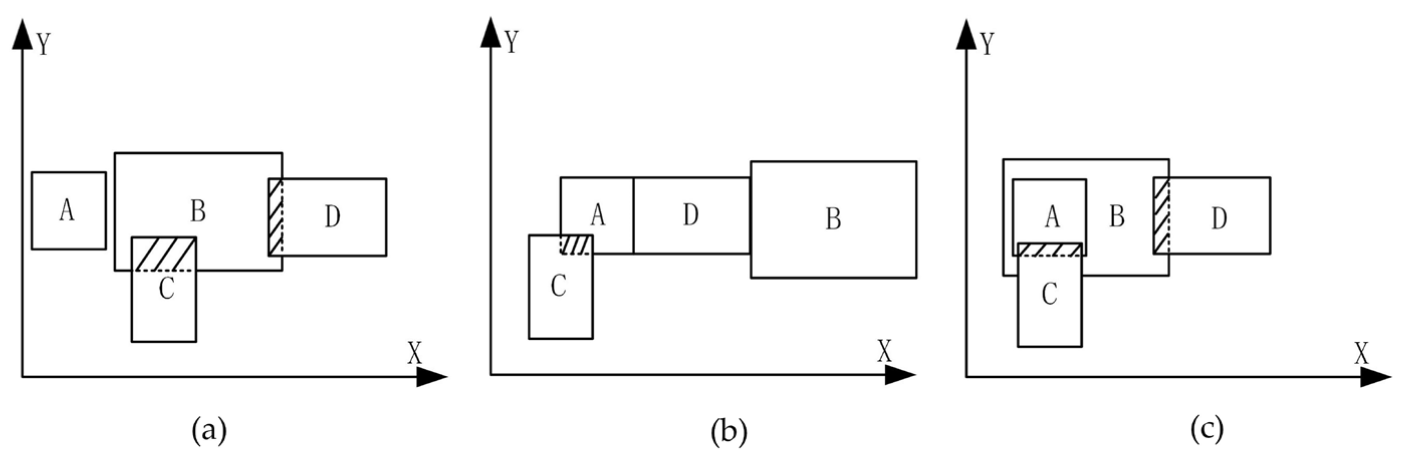
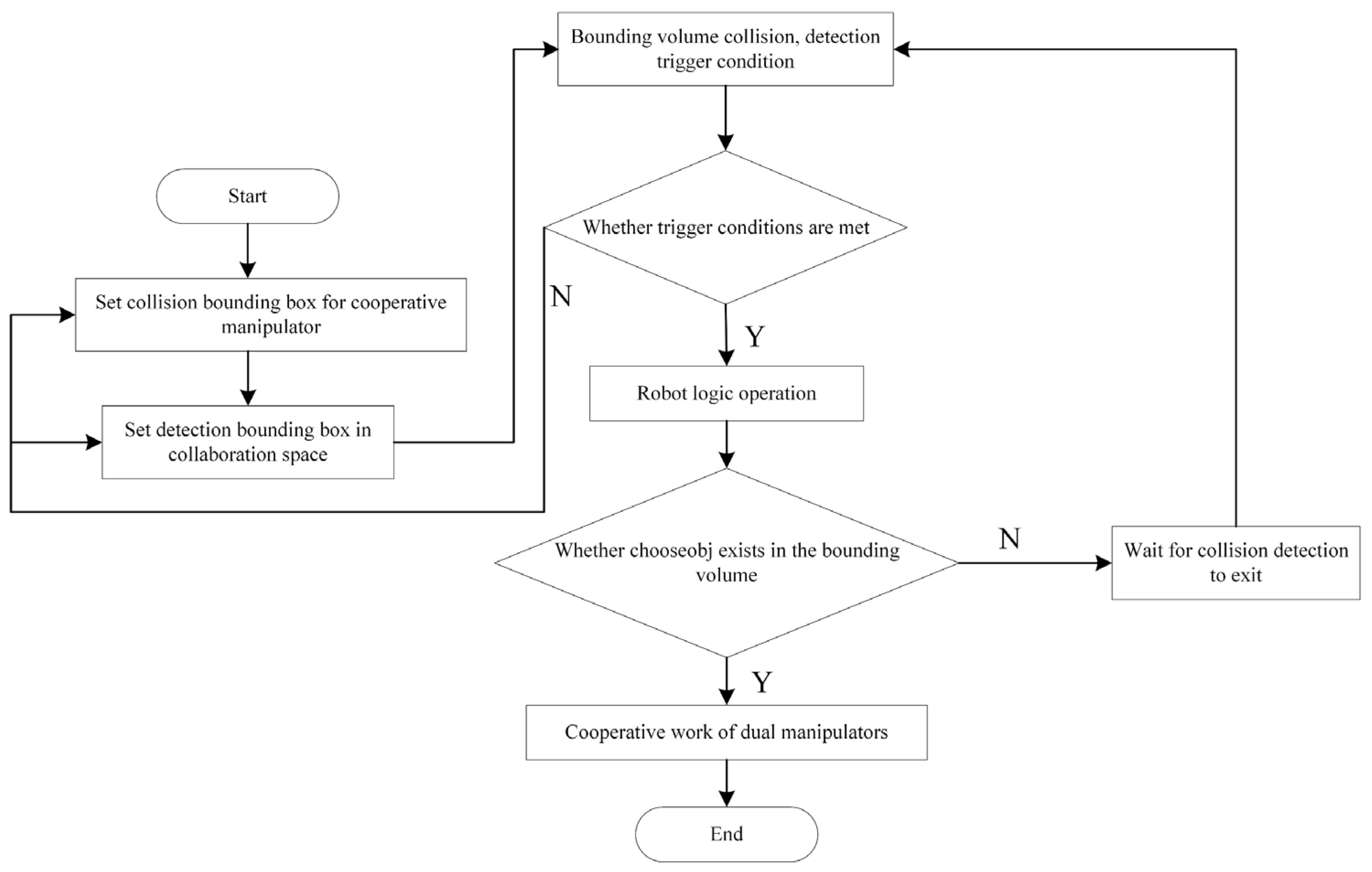
4.2.2. Bounding Volumes Collision Detection Algorithm

The types of bounding volumes include the axis-aligned bounding volume, O-shaped bounding volume, and triangular bounding volume, etc. As the carriers and CBs are regular shapes, the axis-aligned bounding volumes enable the model to be enclosed more evenly and tightly, making it easier to calculate. The shape of the bounding volume is shown in Figure 21.
As a necessary condition for logical triggering, the construction of the bounding volume has a greater role in the operational efficiency of the DT system. A double-layer construction is used in this paper, as shown in Figure 21b. The algorithm is a separated axis detection algorithm. If the projections of two bounding volumes in the direction of the same axis do not overlap, the two bounding volumes are proven to be non-intersecting. If the projections in one direction intersect, a collision may be released. Simultaneously, if the projections in both directions intersect, the two bounding volumes must have collided. Traditional collision detection requires separate detection of the separation axis. However, the double-layered bounding volume only requires collision detection by design in the construction, without having to collide with each bounding volume. The principle of the collision detection algorithm is shown in Figure 22. The traditional collision detection of each bounding volume requires the detection of the separation axis; B is detected with A and B, respectively, when entering the state, and A is detected with C and D, respectively, after waiting for B to exit detection. The double-layer construction bounding volume used in this paper collides with the two bounding volumes C and D at the same time and only requires eight rounds to complete (Figure 22a). There is no need to calculate the collision between B and C (Figure 22b) and the collision between A and D (Figure 22c). Compared with traditional separate collision detection, this can greatly improve computational efficiency.

4.2.3. Logic Judgment Recognition Algorithm

DT systems are prone to breakdown because the logic relationship of the multi-robot cooperative CBFMS is complex. The existing method often involves performing the next action after the collision detection is completed, which tends to cause the system to waste time. The long time operation will cause the memory to be overloaded, and the system will break down. To solve the problem, a logic judgment algorithm based on the collision detection algorithm is proposed in this paper, which can judge the state of the robot arm in real time through collision detection, as shown in Figure 23.
This method involves setting a bounding volume for multiple robots and determining whether there will be a danger by collision detection between the bounding volumes. At the same time, a bounding volume is set in the dangerous area as the detection condition. When the bounding volume of the robot itself collides or enters the area, the presence of danger is detected, and the cooperative robot is stopped by algorithm judgment. When crossing the dangerous area, there is no bounding volume in the boundary area. The exit detection runs normally, and the cooperative robot starts to run. The data collected by the two-arm cooperation robot manufacturing unit after algorithm optimization are shown in Table 3.
The table is judged through memory utilization, frames per second (FPS), and the number of faults, respectively. The memory utilization in the table shows that compared with the traditional method, the optimized method is significantly improved by 23% when the system runs for four hours. The higher the frame rate of FPS, the smoother the picture. The FPS of the system is significantly improved after optimization by the algorithm, effectively solving the problem of long running time with serious frame drops. Over time, the optimization rate of faults is gradually reduced from 66.6% to 33.3%. This proves that the algorithm can effectively increase the stability of the system and its smoothness.

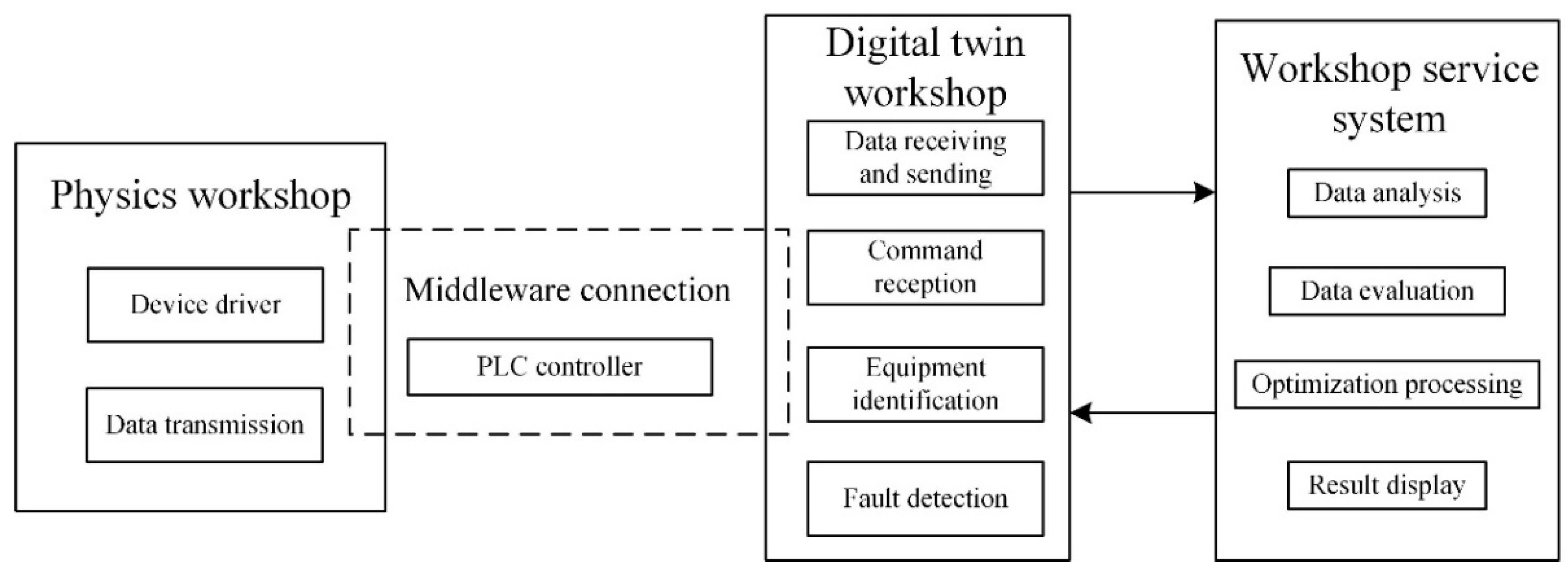
4.3. Data Communication Mechanisms

Data communication, a central part of the DT system, provides the data basis for updating and optimizing the DT system. The DT system for multi-robot collaboration is dynamic and will be generated with the movement of the robot. It contains physical data, behavioral data, visual data, rule data, etc. The physical data include the joint angles and positions generated by the robot movement; the visual data include the size, color, and shape of all the models. The behavioral data include the productivity and status of the entire shop floor. How the physical cell sends the data to the virtual system is key to building the twin system. The mechanisms of data interaction are shown in Figure 24. The DT system needs to process the joint angle, speed, route, time, and other data received from the robot and then drive the DT model to move. The communication between the DT system and the physical workshop is connected through the middleware. The physical workshop controls the actual system through the drive equipment, collects the data generated by the robot controller, and transmits the collected data to the PLC through ethernet. Finally, the network protocol conversion is sent to the virtual system. The virtual system receives and processes the data through the data exchange engine. By analyzing and optimizing the production line data, the workshop service system finally realizes the operation and dynamic display of the DT system. Meanwhile, the optimized data are conveyed to the database for storage.

5. System Feasibility Verification

To verify the success rate and efficiency of manufacturing, the experiments with physical units and virtual systems are conducted, respectively. In the experiment of the robot manufacturing unit, the trajectory planning algorithm is applied to the prototype mainly through the test of manufacturing accuracy and time. By tracking the manufacturing process, the operation of the whole production line and the state of the robot can be known. The experimental physical prototype of the two-arm cooperation robot is shown in Figure 25.
To verify the synchronization relationship between the virtual and the physical system, the physical manufacturing unit is connected to the virtual system. The initial state of the system is adjusted to match the physical operation unit, and the state of the robot is judged by observing the operation process of the physical unit. Data from the physical unit manufacturing process are sent to the virtual system to complete the precise manufacturing of the virtual system, which can monitor the status of the system in real time. At the same time, by observing the trajectory of robots in multi-robot cooperative CBFMS, we can judge whether the two-arm cooperation robots are assembled according to the optimal trajectory, which is of great significance to the practical research of dual-robot-arm cooperation. The experimental software environment is Microsoft Visual Studio 2019 and Unity3D 5.5.2f1 development platform, and the hardware environment is Intel (R) Core (TM) i7-11800H @ 2.3GHz processor and NVIDIA GeForce RTX3060 display adapter.
The multi-robot cooperative CBFMS includes the parts, carriers, robot system, goods shelves, boxes, rails, etc. The robot system is composed of a six-axis robot arm, a four-axis robot arm, a parallel robot, a mobile robot, end clamping jaws, and industrial control system. The composition of the DT system and the information of each production unit are displayed through data interaction, which is convenient for customers to observe the productivity and operation status of the equipment. The CB flexible manufacturing DT system is shown in Figure 26.
Through a visual display of DT system data, the whole state of the production line can be clearly seen in the main interface. The DT system of the multi-robot collaborative CBFMS built for a 3D engine in the middle can visually display the dynamic effect of each manufacturing unit. The other parts visually display the relevant operating parameters generated by system manufacturing in the form of data diagrams, including the production status, production data, time cost, equipment energy consumption, and fault status. The lower part is the buttons of each unit of the system. Each unit system is switched by clicking the button on the main interface. After entering, the production status of each unit is viewed, including the total cost of path length, time, manufacturing accuracy, etc. The different units are shown separately in Figure 27.
Serious consequences will occur if the fault cannot be found in time. The DT system’s visual service is used for fault display. When the real physical production line encounters problems, it will send a signal to the DT system. When the DT system receives the fault signal, the corresponding fault unit will brighten, which is convenient for operators to find the fault in time. The DT system highlighted when a unit fails is shown in Figure 28.
When a unit in the system fails, the unit in question lights up a red light, and the whole system stops working. When entering the work interface of the unit, the data of the whole system turn red and stop updating, which facilitates the operator finding the fault.
To verify the validity of the design scheme in this paper, the multi-robot cooperative CBFMS is compared with the traditional CBs manufacturing scheme through a digital visual service system. The results are shown in Table 4.
As can be seen in Table 4, the manufacturing time of the scheme involved in this paper is 13.42 s shorter and 22% more efficient than that of the traditional semi-automatic production line. Compared with the traditional methods, the scheme proposed in this paper can save a lot of manual operations and achieve fully automated production. By building a supporting DT system, the CBFMS production line can be optimized and improved. In the face of different specifications and models of products, changes can be made according to different process requirements to truly achieve flexible production and maximize benefits.

6. Conclusions

According to the complex and changeable assembly requirements for CBs, a multi-robot collaborative CBFMS is proposed. This method can realize the fully automatic manufacturing of CBS from parts loading to storage. To improve the assembly efficiency of key units in multi-robot collaborative CBFMS, the method of collaborative assembly of parts with two-arm cooperation robots is adopted. Finally, the DT system of multi-robot collaborative CBFMS is built to realize the prediction and monitoring of the production line, which can improve the intelligence level of the entire production system.
(1)
Compared with the traditional semi-automatic production line, the overall assembly efficiency is increased by 22%. At the same time, this method can solve the problems of excessive rigidity and single assembly method in traditional assembly schemes.
(2)
Compared with the traditional single-robot system, the efficiency of two-arm cooperation robot assembly can be increased by 63%. This method can improve the whole CBFMS production rhythm and speed up the production process by improving the assembly efficiency of key units.
(3)
The DT system of multi-robot collaborative CBFMS can accurately and timely express each process of the production unit, including the selection of the best process of the whole system and the accurate mapping of actual production objectives. The proposed framework provides a set of reference implementation schemes for the construction of a physical workshop, which can greatly improve the production efficiency of CBs and optimize the structure of the production line.
In the future, we hope to introduce human–machine–environment integration and DT system data prediction analysis. Robots can act quickly when they judge human behavior and environmental changes, and their efficiency will be further enhanced. At the same time, a large number of data models are analyzed by building the DT system, and the future trend is predicted by combining the AI algorithm.

Author Contributions

Conceptualization, L.W. and L.S.; methodology, L.W. and L.S.; software, L.W. and H.Z.; validation, L.W.; formal analysis, L.W. and L.S.; investigation, L.W. and L.S.; resources, L.S.; data curation, L.W. and H.Z.; writing—original draft preparation, L.W. and L.S.; writing—review and editing, L.W. and L.S.; visualization, L.W.; supervision, L.W.; project administration, L.S.; funding acquisition, L.W. and L.S. All authors have read and agreed to the published version of the manuscript.

Funding

This research was funded by the Key R&D Project of Zhejiang Province, grant number No.2021C01046; by the Basic Industrial Science and Technology Project of Wenzhou, grant number G20210020; by the Zhejiang Xinmiao Talents Program, grant number 2022R429B048.

Institutional Review Board Statement

Not applicable.

Informed Consent Statement

Not applicable.

Data Availability Statement

Not applicable.

Acknowledgments

We would like to thank all the reviewers for their helpful suggestions.

Conflicts of Interest

The authors declare no conflict of interest.

Abbreviations

CBsCircuit breakers
CBFMSCircuit breaker flexible manufacturing system
DTDigital twin
FMSFlexible manufacturing system
DTSDigital twin shopfloor
PSOParticle swarm optimization
LTLead time
ATTActual Takt time
CTCycle time
PLCProgrammable logic controller
MDPMarkovian decision process
DDPGDeep deterministic policy gradient
DQNDeep Q-network
ARAugmented reality
FPSFrames per second

References

  1. Wang, Y.; Li, W.; Wu, X.; Wu, X. A Novel Bidirectional Solid-State circuit breaker for DC Microgrid. IEEE Trans. Ind. Electron. 2019, 66, 5707–5714. [Google Scholar] [CrossRef]
  2. Szulborski, M.; Łapczyński, S.; Kolimas, Ł.; Zalewski, D. Transient thermal analysis of the circuit breaker current path with the use of fea simulation. Energies 2021, 14, 2359. [Google Scholar] [CrossRef]
  3. Ghobakhloo, M. Industry 4.0, digitization, and opportunities for sustainability. J. Clean. Prod. 2020, 252, 119869. [Google Scholar] [CrossRef]
  4. Kousi, N.; Gkournelos, C.; Aivaliotis, S.; Giannoulis, C.; Michalos, G.; Makris, S. Digital Twin for adaptation of robots’ behavior in flexible robotic manufacturing lines. Procedia Manuf. 2019, 28, 121–126. [Google Scholar] [CrossRef]
  5. Müller, R.; Vette, M.; Geenen, A. Skill-based dynamic task allocation in human-robot-cooperation with the example of welding application. Procedia Manuf. 2017, 11, 13–21. [Google Scholar] [CrossRef]
  6. Monguzzi, A.; Maiocchi, M.; Zanchettin, A.M.; Rocco, P. Flexible robotic strategy for the manufacturing of ring-shaped elastic objects. Procedia Comput. Sci. 2022, 200, 376–385. [Google Scholar] [CrossRef]
  7. Cui, H.; Sun, R.; Fang, Z.; Lou, H.; Tian, W.; Liao, W. A novel flexible two-step method for eye-to-hand calibration for robot manufacturing system. Meas. Control 2020, 53, 2020–2029. [Google Scholar]
  8. Chen, X.; Shu, L.; Leng, Y.; Yang, Y. Design of Digital Twin system for flexible manufacturing workshop of circuit breaker. Comput. Eng. Appl. 2022, 58, 245–257. [Google Scholar]
  9. Guo, J.; Hong, H.; Zhong, K.; Liu, X.; Guo, Y. A Digital Twin-based production control method for aerospace manufacturing workshops. China Mech. Eng. 2020, 31, 808–814. [Google Scholar]
  10. Fu, Y.; Cao, H.; Gao, W.; Gao, W. Digital Twin-driven remaining life prediction of aero-engine turbine discs. J. Mech. Eng. 2021, 57, 106–113. [Google Scholar]
  11. Liu, S.; Bao, J.; Lu, Y.; Li, J.; Lu, S.; Sun, X. Digital Twin modeling method based on biomimicry for machining aerospace components. J. Manuf. Syst. 2021, 58, 180–195. [Google Scholar] [CrossRef]
  12. Phanden, R.K.; Sharma, P.; Dubey, A. A review on simulation in Digital Twin for aerospace, manufacturing and robotics. Mater. Today Proc. 2021, 38, 174–178. [Google Scholar] [CrossRef]
  13. Malik, A.A.; Brem, A. Digital twins for collaborative robots: A case study in human-robot interaction. Robot. Comput. Integr. Manuf. 2021, 68, 102092. [Google Scholar] [CrossRef]
  14. Abbasi, R.; Yanes, A.R.; Villanuera, E.M.; Ahmad, R. Real-time implementation of digital twin for robot based production line. In Proceedings of the Conference on Learning Factories (CLF), Graz, Austria, 1–2 July 2021. [Google Scholar]
  15. Wang, Q.; Jiao, W.; Wang, P.; Zhang, Y. Digital twin for human-robot interactive welding and welder behavior analysis. IEEE/CAA J. Autom. Sin. 2020, 8, 334–343. [Google Scholar] [CrossRef]
  16. Rizk, Y.; Awad, M.; Tunstel, E.W. Cooperative heterogeneous multi-robot systems: A survey. ACM Comput. Surv. 2019, 52, 1–31. [Google Scholar] [CrossRef]
  17. Tuci, E.; Alkilabi, M.H.M.; Akanyeti, O. Cooperative object transport in multi-robot systems: A review of the state-of-the-art. Front. Robot. AI 2018, 5, 59. [Google Scholar] [CrossRef]
  18. Xiao, J.; Dou, S.; Zhao, W.; Liu, H. Sensorless human-robot collaborative assembly considering load and friction compensation. IEEE Robot. Autom. Lett. 2021, 6, 5945–5952. [Google Scholar] [CrossRef]
  19. Liu, H.; Pan, X.; Zhang, Q.; Zhang, H.; Li, P.; Tian, W. Key Technologies of Cooperative Assembly of Dual Robots for Aircraft Narrow Space. Aviat. Manuf. Technol. 2022, 65, 55–62. [Google Scholar]
  20. Tao, F.; Zhang, M. DT shop floor: A Newshop floor paradigm towards smart manufacturing. IEEE Access 2017, 5, 20418–20427. [Google Scholar] [CrossRef]
  21. Pérez, L.; Rodríguez-Jiménez, S.; Rodríguez, N.; Usamentiaga, R.; Garcíaet, D.F. Digital Twin and virtual reality based methodology for multi-robot manufacturing cell commissioning. Appl. Sci. 2020, 10, 3633. [Google Scholar] [CrossRef]
  22. Han, Y.; Shu, L.; Wu, Z.; Zhang, G.; Cai, Z. Research of flexible assembly of miniature circuit breakers based on robot trajectory optimization. Algorithms 2022, 15, 269. [Google Scholar] [CrossRef]
  23. Yang, Y.; He, H.; Shu, L.; Yang, M.; Wu, Z. A Digital Twin robot for flexible manufacturing of circuit breaker and its motion control. Comput. Integr. Manuf. Syst. 2020, 26, 2915–2926. [Google Scholar]
  24. Umay, I.; Fidan, B.; Melek, W. An integrated task and motion planning technique for multi-robot-systems. In Proceedings of the IEEE International Symposium on Robotic and Sensors Environments (ROSE), Ottawa, ON, Canada, 17–18 June 2019. [Google Scholar]
  25. Yang, Y.; Li, J.; Peng, L. Multi-robot path planning based on a deep reinforcement learning DQN algorithm. CAAI Trans. Intell. Technol. 2020, 5, 177–183. [Google Scholar] [CrossRef]
  26. Zhang, L.; Sun, Y.; Barth, A.; Ma, O. Decentralized control of multi-robot system in cooperative object transportation using deep reinforcement learning. IEEE Access 2020, 8, 184109–184119. [Google Scholar] [CrossRef]
  27. Gong, H.; Wang, P.; Ni, C.; Cheng, N. Efficient path planning for mobile robot based on deep deterministic policy gradient. Sensors 2022, 22, 3579. [Google Scholar] [CrossRef]
  28. Xie, L.; Miao, Y.; Wang, S.; Blunsom, P.; Wang, Z.; Chen, C.; Markham, A.; Trigoni, N. Learning with stochastic guidance for robot navigation. IEEE Trans. Neural Netw. Learn. Syst. 2020, 32, 166–176. [Google Scholar] [CrossRef]
  29. Yu, J.; Su, Y.; Liao, Y. The path planning of mobile robot by neural networks and hierarchical reinforcement learning. Front. Neurorobot. 2020, 14, 63. [Google Scholar] [CrossRef]
  30. Tao, F.; Liu, W.; Liu, J.; Liu, X.; Liu, Q.; Qu, T.; Hu, T.; Zhang, Z.; Xiang, F.; Xu, W.; et al. Digital Twin and its application exploration. Comput. Integr. Manuf. Syst. 2018, 24, 1–18. [Google Scholar]
  31. Li, S.; Shu, L.; Yang, Y.; Chen, D. A fast architecture approach for Digital Twin shop systems with parallel computation of logic and model data. J. Mech. Eng. 2021, 57, 76–85. [Google Scholar]
  32. Liu, L.; Du, H.; Wang, H.; Liu, T. Construction and application of Digital Twin system for workshop production process. Comput. Integr. Manuf. Syst. 2019, 25, 1536–1545. [Google Scholar]
Figure 1. Internal structure and parts composition of a CB.
Applsci 13 02721 g001
Figure 2. Traditional CBs semi-automatic production line.
Applsci 13 02721 g002
Figure 3. Single-robot flexible manufacturing system: (a) Crucial unit of parts’ posture adjustment; (b) Individual part attitude adjustment process.
Applsci 13 02721 g003
Figure 4. The construction of the multi-robot collaborative CBs flexible manufacturing system.
Applsci 13 02721 g004
Figure 5. Robot’s flexible multi-gripper claw construction.
Applsci 13 02721 g005
Figure 6. The assembly mode of two-arm cooperation robot.
Applsci 13 02721 g006
Figure 7. Framework of the DT flexible manufacturing system.
Applsci 13 02721 g007
Figure 8. Two-arm cooperation robot’s D-H coordinate system.
Applsci 13 02721 g008
Figure 9. Monte Carlo method collaborative spatial point cloud map.
Applsci 13 02721 g009
Figure 10. Key points in collaborative manufacturing of two-arm cooperation robot.
Applsci 13 02721 g010
Figure 11. Reinforcement learning mechanism.
Applsci 13 02721 g011
Figure 12. DDPG algorithm framework.
Applsci 13 02721 g012
Figure 13. Two-arm cooperation robot in Unity environment.
Applsci 13 02721 g013
Figure 14. Convergence iteration curve during training.
Applsci 13 02721 g014
Figure 15. The success rate of the robot in completing the task.
Applsci 13 02721 g015
Figure 16. Two-arm cooperation robots working together to grip parts.
Applsci 13 02721 g016
Figure 17. Deviation between actual position and ideal target position.
Applsci 13 02721 g017
Figure 18. Logical relation construction of robot model.
Applsci 13 02721 g018
Figure 19. Comparison before and after model optimization.
Applsci 13 02721 g019
Figure 20. Kinematic control algorithm for robot model: (a) Digital twin model; (b) Kinematic algorithm; (c) Animator control.
Applsci 13 02721 g020
Figure 21. Model bounding volume handling: (a) The directional bounding volume; (b) The double-layer construction bounding volume; (c) The axis-aligned bounding volume.
Applsci 13 02721 g021
Figure 22. Principle of the collision detection algorithm: (a) Status one; (b) Status two; (c) Status three.
Applsci 13 02721 g022
Figure 23. Logic judgment detection algorithm flowchart.
Applsci 13 02721 g023
Figure 24. Twin system data communication mechanisms.
Applsci 13 02721 g024
Figure 25. Two-arm cooperation robot physical prototype.
Applsci 13 02721 g025
Figure 26. Main interface of DT system of multi-robot cooperative CBFMS.
Applsci 13 02721 g026
Figure 27. DT system unit interface of multi-robot cooperative CBFMS.
Applsci 13 02721 g027
Figure 28. System display in the event of a fault.
Applsci 13 02721 g028
Table 1. ROKAE XB-4 D-H parameters.
JointRotation Angle ( θ i ) Connecting   Rod   Length   ( a i ) Joint   Offset   ( d i ) Torque   ( α i )
1 θ 1 40 mm0−90
2 θ 2 275 mm00
3 θ 3 25 mm0−90
4 θ 4 0280 mm90
5 θ 5 00−90
6 θ 6 073 mm0
Table 2. Comparison of time and success rate of grasping five parts before and after optimization.
Part NameTime/sPass Rate (%)
TraditionalOptimizedOptimization Rate (%)TraditionalOptimized
Arc extinguishing chamber6.523.6444.1792.595.6
Magnetic system10.573.8663.4891.795.3
Yoke5.894.5323.099294.2
Big-U rod7.363.2755.5793.493.9
Handle5.272.6250.2892.294.9
Table 3. Comparison of system operation data before and after optimization.
Time/hMemory
Utilization (%)
FPSNumber of Respective Faults
TraditionalOptimizedTraditionalOptimizedTraditionalOptimizedOptimization Rate (%)
1261279.2163.53166.6
2392361.71486350
3482745.3125.78537.5
4553232.7117.89633.3
Table 4. Comparison between the traditional CBs manufacturing line and the multi-robot cooperative CBFMS.
FunctionMulti-Robot Cooperative CBFMSSemi-Automatic Manufacturing Line
Production time of one CB (s)47.5861
Whether there is labornoyes
Whether the process can be changedyesno
Whether the process design is perfectyesno
Disclaimer/Publisher’s Note: The statements, opinions and data contained in all publications are solely those of the individual author(s) and contributor(s) and not of MDPI and/or the editor(s). MDPI and/or the editor(s) disclaim responsibility for any injury to people or property resulting from any ideas, methods, instructions or products referred to in the content.

