Article

Dynamic Behavior Analysis of I-Shaped RC Beams under Combined Blast and Impact Loads

School of Highway, Chang’an University, Xi’an 710061, China
*
Author to whom correspondence should be addressed.
Appl. Sci. 2023, 13(3), 1943; https://doi.org/10.3390/app13031943
Submission received: 14 January 2023 / Revised: 31 January 2023 / Accepted: 1 February 2023 / Published: 2 February 2023
(This article belongs to the Topic Dynamical Systems: Theory and Applications)

Abstract

:

Featured Application

Numerical simulation of I-shaped RC beams under combined blast and impact loads.

Abstract

The existing literature mainly focuses on the research of reinforced concrete (RC) beams under a single load such as blast or impact. In this paper, the slab–rib–slab RC beam, a new type of structure widely used in bridge structures, was taken as the research object. The explicit dynamic analysis software LS-DYNA was used to numerically analyze the dynamic response and failure behavior of I-shaped RC beams under combined blast and impact loads. For this reason, an effective numerical analysis model was obtained by carrying out experiments on I-shaped RC beams under contact explosion. The key factors affecting the dynamic response of the structure under combined loads were numerically analyzed. Numerical results showed that different load application sequences have important effects on the dynamic response of the structure. When the impact load was first applied to the structure, more severe concrete damage and deformation occured in the depth direction of the beam. However, when the blast load was first applied to the structure, the concrete at the lower flange was damaged in the span direction of the beam due to tension, and no large-scale concrete spallation occurred in the depth direction. This was mainly due to the different mechanisms of blast and impact loads. In addition, the vulnerability of the I-shaped RC beams varied with some structural parameters, including span, depth, and configuration of reinforcement. At the same time, the results showed that the structure is more sensitive to changes in structural parameters when it is first subjected to impact loads.

1. Introduction

With the frequent occurrence of military conflicts, terrorist attacks, and bridge safety accidents, extreme loads such as blasts or impacts have become potential threats to bridge structures [1]. As an important flexural-critical member of the bridge structure, it is crucial to ensure that the beam can withstand a certain degree of extreme load; otherwise, it may lead to the collapse of the whole bridge. The existing literature mainly focuses on the research of reinforced concrete (RC) beams under a single load such as blast or impact.
Regarding blast loads, existing studies have evaluated the dynamic response of RC slabs [2,3,4,5] and RC columns [6,7,8,9,10]. The experimental and numerical studies on RC beams under blast loading are limited, and the research objects are mainly RC beams with rectangular cross-sections. Yao et al. studied the impact of different stirrup ratios on the blast resistance and damage characteristics of reinforced concrete through experiments and numerical analysis. It was found that the degree of concrete damage decreases with the increase of the stirrup ratio, and the empirical formulas of the stirrup ratio and deflection were given [11]. Fan et al. proposed a theoretical approach to predict the dynamic response of externally prestressed reinforced concrete (EPC) beams under blast loading and provided useful design insights into three important parameters affecting the dynamic response of the structure [12]. Liu et al. carried out four-point bending experiments of the glass fiber-reinforced polymer (GRFP)-reinforced bar concrete beams under close blast. It was proven that GRCB has a stronger blast resistance through the remaining bearing capacity of the beam [13]. Algassem et al. studied the impact of steel fibers on the blasting performance of high-strength concrete beams and carried out related experimental research. The results showed that steel fibers can replace the transverse reinforcement and reduce the shear failure caused by explosion [14]. Liu et al. conducted an explosion test analysis on 10 half-scale beams. At the same proportional distance, the damage of RC beams with a larger blast mass was more serious. At the same time, the empirical formula between the mid-span displacement and the proportional distance was obtained [15].
Compared with blast loads, the existing literature has more sufficient research on RC beams under impact loads. Fujikake et al. carried out the drop-weight impact test of reinforced concrete beams to study the response changes of the drop-weight height and the amount of longitudinal reinforcement to RC beams under impact loads. It was found that the local and global response of the structure depends on different loading rates [16]. Li et al. studied the influence of the overall stiffness of the structure on the impact force distribution through LS-DYNA. A two degrees of freedom (2DOF) analytical model was developed for an RC beam under drop-weight impact by predicting impact forces using a fiber beam section analysis method [17]. Cheng et al. used a numerical analysis method to study the effect of impact velocity on the response and failure of RC beams. Analytical equations that predict the failure modes in RC beams from bending to shear were presented [18]. Almusallam et al. designed the projectile impact experiment of mixed fiber-reinforced concrete beams and found that mixed fibers can improve the energy absorption of beams and improve the impact response of RC beams [19]. Pham et al. used drop-weight tests to study the mechanical properties of RC beams with cushions. High energy-absorbing pads were used to protect RC beams subjected to impact loads and a simplified equation for the maximum deflection of beams with pads was established [20].
From the above studies, it can be concluded that the main reason for the difference in the dynamic response of structures caused by blast loads and impact loads is that the load application mechanisms are different. The shock wave of the explosion load is applied to the structure in the form of a uniform load. When the explosion energy is large enough, the concrete on the blast surface of the beam will be damaged under compression, and the concrete on the back blast surface will be damaged due to tension. However, RC beams may undergo flexural failure, shear failure, or flexural-shear failure under different conditions. This mainly depends on the energy of the blast load, which is generally related to the proportional distance Z of the explosive.
Z = R W 1 / 3
where R is the distance from the center of the explosive to the structure and W is the weight of the explosive. However, the impact load is applied to the structure in the form of the concentrated load, and the dynamic response of the structure is closely related to the impact rate and impact duration. Flexural failure can occur when a structure is subjected to low rate but long duration impact loading, similar to static loading. Under high-rate and short-duration impact loads, structures may undergo localized shear failure. At moderate rates, combined shear and flexural failure may occur. Under high-rate and short-duration impact loads, structures may undergo localized shear failure. At moderate rates, combined shear and bending failure may occur.
Many scholars have conducted much research on the damage mechanism and failure behavior of RC beams under impact or blast loads. However, in reality, except for the single load, the bridge structure may also be subjected to combined blast and impact loads. For example, when a car or ship carrying explosives hits a beam or column, the structure is subjected to impact loads that may subsequently cause blast loads [21,22]. When the high-speed projectile explodes, the structural fragments of some explosive objects may be applied to the structure in the form of impact load after the explosion [23]. Therefore, it is very important to analyze the dynamic response and failure behavior of bridge structures under combined loads. At the same time, the I-shaped RC beam, as a hollow member, has a slab–rib–slab structure. Because of its structural advantages such as saving materials and reducing self-weight, it is widely used in highway bridges. However, there are no reports on its research under extreme loads. Therefore, the main purpose of this paper was to use explicit dynamic analysis software LS-DYNA to numerically analyze the dynamic mechanical response and failure behavior of I-shaped RC beams under combined loads. The key factors affecting the dynamic response of I-shaped RC beams under combined loads were evaluated, in order to provide a theoretical basis for the protection design, prevention strategies, and improvement methods of this type of structure. To this end, we have carried out the following work:
(1) Numerical model verification under single load: Carry out explosion experiments on I-shaped RC beams to obtain an effective numerical analysis model. The numerical model with the same material model was verified experimentally under impact loading.
(2) Numerical calculation under combined loads: Based on the verification of the numerical model, the dynamic response of the I-shaped RC beam under combined loads of near-field blast loads and medium-rate impact loads was analyzed.
(3) Parameter analysis: The impact of different load application sequences and different structural parameters on the vulnerability of the structure was evaluated.

2. Finite Element Analysis of the I-Shaped RC Beam under the Blast Load

There is no relevant research on I-shaped RC beams under blast or impact loads in the existing literature. Therefore, the experimental components of I-shaped RC beams were designed and manufactured, and the contact explosion experiments were carried out. At the same time, the explicit dynamic analysis software LS-DYNA was used to establish the numerical model. The numerical simulation results were compared with the experimental results to verify the feasibility of the numerical model and algorithm.

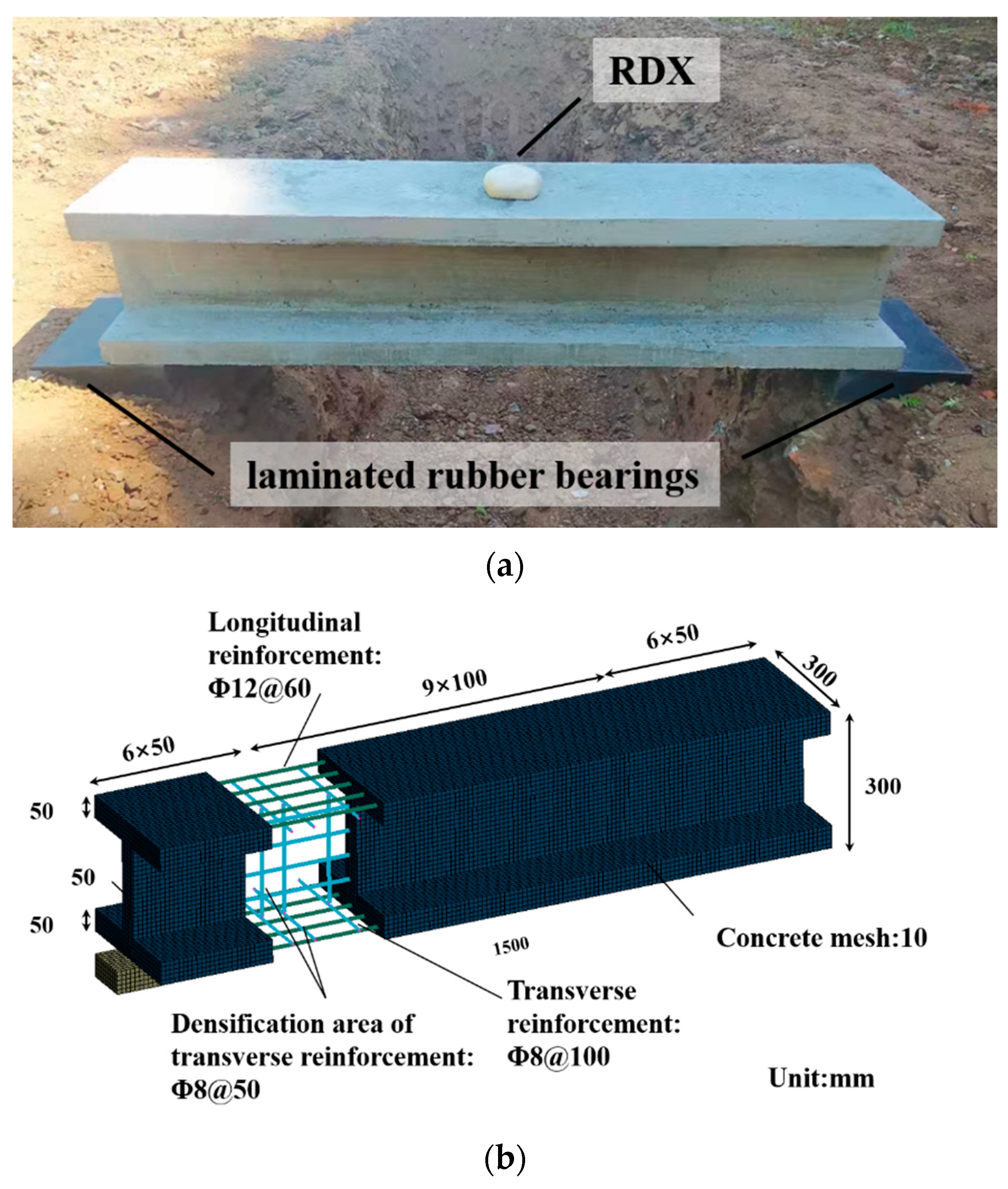
2.1. Structural Model

The experimental beam has an I-shaped cross-section. The height, width, and span of the beam are 300 mm, 300 mm, and 1500 mm, respectively. The thickness of the top plate, vertical ribs, and bottom plate are all 50 mm. Considering possible flexural damage, 10 longitudinal reinforcements with a diameter of 12 mm are arranged on the top and bottom plates, and the reinforcement ratio is 2.50%. At the same time, transverse reinforcement ratios of 0.75% and 1.41% are arranged in the mid-span and supporting point to strengthen the shear resistance under the impact loadings. During the experiment, laminated rubber bearings were placed under the bottom plate of the I-shaped RC beam to provide simple support for the structure. The explosive uses the hexogen (RDX) trimmed into a cube to detonate in contact with the mid-span position of the top plate. The explosives in this experiment are mixed by RDX and adhesives, of which 86% is RDX. In the finite element numerical model, solid elements are used for concrete and supports, and beam elements are used for steel bars. Figure 1 shows the experimental and numerical model. According to the literature [24], for concrete materials with a compressive strength between 20–58 Mpa, the recommended mesh size is 8–32 mm. Considering that the concrete of about 50 MPa is selected for the experiment, after preliminary calculations, different grid sizes mainly affect the calculation time. In order to ensure calculation efficiency and accuracy, the grid size selected for the numerical model is 10 mm, the number of nodes in the model is 79,809, and the number of units is 62,092.

2.2. Material Model

In order to describe the nonlinear characteristics of the material, the material behavior of concrete was modeled using the MAT_CSCM_CONCRETE Keywords: The model included hardening, damage, and strain rate effects of the material under the blast loading. The dynamic enhancement factor (DIF) was used to reflect the enhancement effect of the material strength, and the concrete compressive strength enhancement factor (CDIF) [25] is:
C D I F = f c d f c s = { ( ε ˙ c d ε ˙ c s ) 1.026 α γ ( ε ˙ c d ε ˙ c s ) 1 / 3 f o r f o r ε ˙ c d 30 s 1 ε ˙ c d > 30 s 1
where f c d is the dynamic compressive strength under the strain rate ε ˙ c d ; f c s is the static compressive strength under the strain rate ε ˙ c s ; the interval of the dynamic strain rate ε ˙ c d is [ 3 × 10 5 s 1 , 3 × 10 2 s 1 ] , and the static strain rate ε ˙ c s is 3 × 10 5 s 1 ; f c 0 = 10 MPa ; α = 1 / ( 5 + 9 f c s / f c 0 ) ,   l o g γ = 6.156 α 2 . The tensile strength enhancement factor (TDIF) of the concrete is [26]:
T D I F = f t d f t s = { ( ε ˙ t d ε ˙ t s ) δ β ( ε ˙ t d ε ˙ t s ) 1 / 3 f o r f o r ε ˙ t d 1 s 1 ε ˙ t d > 1 s 1
where f t d is the dynamic compressive strength at the strain rate ε ˙ t d ; f t s is the static compressive strength at the strain rate ε ˙ t s ; the interval of the dynamic strain rate ε ˙ t d is [ 10 6 s 1 ,   160 s 1 ] , the static strain rate ε ˙ c s is 10 6 s 1 ;   δ = 1 / ( 1 + 8 f c s / f c 0 ) ,   f c 0 = 10 MPa ;   l o g β = 6 δ 2 .
In order to accurately describe the mechanical characteristics of the reinforcement, the keyword MAT_PLASTIC_KINEMATIC was used for simulation [26]. At the same time, the Cowper–Symonds model, which can consider both the strain rate effect and the dynamic strengthening effect, was used for analysis. The yield stress values of the transverse and longitudinal reinforcement are 320.3 MPa and 410.6 MPa, respectively. When the maximum principal strain exceeds 0.14, the reinforcement element quits working. The model strain rate enhancement factor was calculated as [27]:
D I F s = 1 + ( ε ˙ C ) 1 / P
where ε ˙ is the strain rate of the reinforcement, C and P are the strain rate parameters of the Cowper–Symonds model.
CONSTRAINED_LAGRANGE_IN_SOLID was used for coupling between reinforcement and concrete elements. According to [24], frictionless sliding between steel and concrete elements was considered, allowing uniform meshing over the whole structure. In addition, the keyword MAT_VISCOELASTIC was used to simulate the material of the rubber bearing. RDX, as a high explosive, has an internal energy almost 1.5 times that of trinitrotoluene (TNT), and a density of about 1890 kg/m3. For numerical analysis, TNT is a commonly used material in explicit material libraries. Therefore, in order to facilitate the calculation and quantitative comparison of the explosive performance of the structure under different explosion scenarios, the TNT equivalent coefficient was used to convert the RDX weight into the TNT equivalent weight. Use the keyword LOAD_BLAST_ENHANCED to simulate blast loads, where the default explosive is TNT. Set a blast surface on the structure with the LOAD_BLAST_SEGMENT_SET command to simulate the interaction between the blast shock wave and the structure. Some material properties are shown in Table 1.

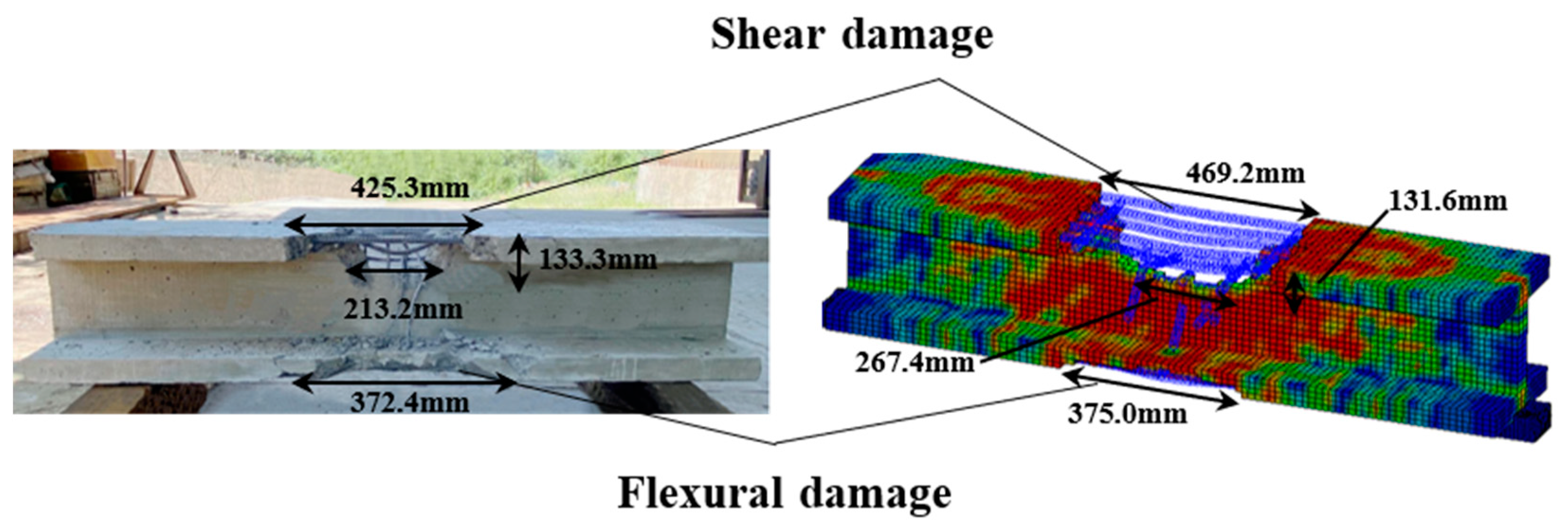
2.3. Result Analysis

Figure 2 compares the finite element numerical results and experimental results of the I-shaped RC beam under blast loading. The results show that when the weight of RDX is 100 g, the blast surface of the beam is subjected to instantaneous high-intensity explosion load. Shear failure occurred on the top plate, and large-scale concrete spalling occurred locally. The length of the damaged region is 425.3 mm. The shock wave propagates downward through the top plate, and the shear failure extends to the vertical rib area. The damage depth was 133.4 mm, which is 44.4% of the beam height, and the concrete at the edge of the bottom slab was cracked. Under instantaneous impact and high temperature, the longitudinal reinforcement of the top plate expanded, and the transverse reinforcement in the damaged area reached the ultimate strength and breaks. During the explosion process of the component, the kinetic energy generated by the explosion shock caused the reinforcement to vibrate at high frequency, and the crack on the top plate of the component extended longitudinally. According to the finite element numerical simulation results, the failure behavior and damage state of the components were basically consistent with the experimental results, and the error value was about 10%. Therefore, it can be considered that the method of using the numerical model and algorithm to simulate the dynamic response of I-shaped RC beams under blast load is reliable.

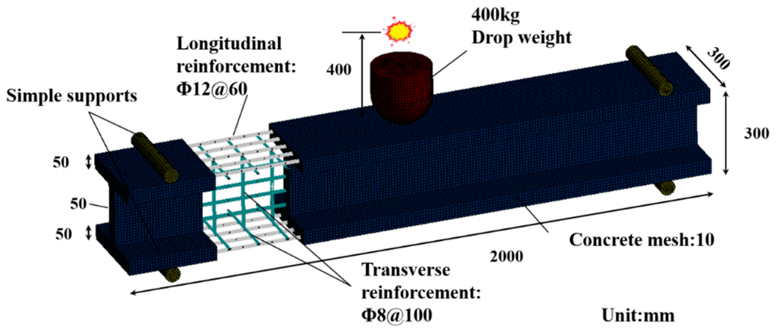
3. Finite Element Analysis of the RC Beam under the Impact Load

Since there is no experimental research on I-shaped RC beams under impact loads, we established a finite element numerical model using the explicit dynamics software LS-DYNA based on the 400 kg drop-weight experiment performed on the RC beam by Fujikake et al. [16]. Numerical results were compared with the impact experimental results using the same material model, contacts, and algorithms as described above for the application of the blast load.

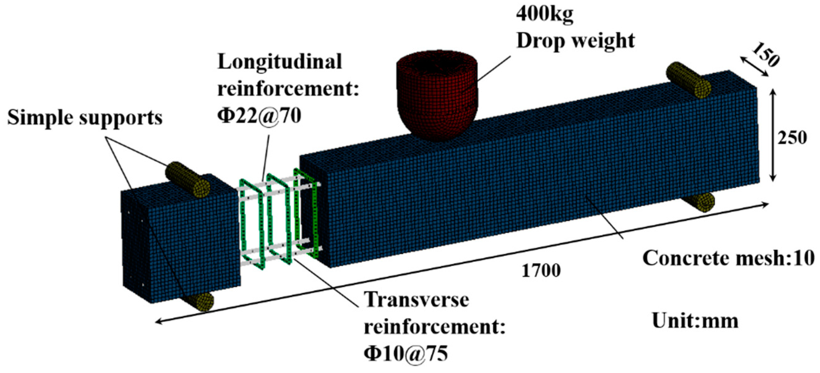
3.1. Structural Model

The experimental beam has a rectangular cross-section, and the height, width, and span dimensions are 250 mm, 150 mm, and 1700 mm, respectively. The thickness of the concrete cover is 40 mm, and two longitudinal bars with a diameter of 22 mm are arranged on the compression side and the tension side of the beam respectively. The longitudinal reinforcement ratio is 2.46%. Stirrups with a diameter of 10 mm and a spacing of 75 mm are arranged in the span direction of the beam. A drop weight with a mass of 400 kg is freely dropped from a height of 2.4 m to the mid-span of the beam with a drop loader. The impact head of the drop hammer is a hemispherical tip with a radius of 90 mm. The concrete beams are supported by special devices that allow them to rotate freely while preventing the structure from moving. Solid elements are used for the concrete and drop hammer, and beam elements are used for the steel bars. The grid size of the numerical model is 10 mm. Figure 3 is the numerical analysis model of the experimental beam.

3.2. Material Model

The concrete material was simulated using the keyword MAT_CSCM_CONCRETE, and the reinforcement was simulated using the keyword MAT_PLASTIC_KINEMATIC. The reinforcement and concrete were coupled using the keyword CONSTRAINED_LAGRANGE_IN_SOLID. These material models are all the same as when the blast loads were applied. At the same time, the keyword MAT_GRAD was used to simulate the drop weight. According to the falling height of the drop weight, the initial velocity was set by the keyword INTIAL_VELOCITY_GENERATION. The keyword AUTOMATIC_SURFACE_TO_SURFACE was used to define the contact between the drop weight and the structure. Some material properties are shown in Table 2.

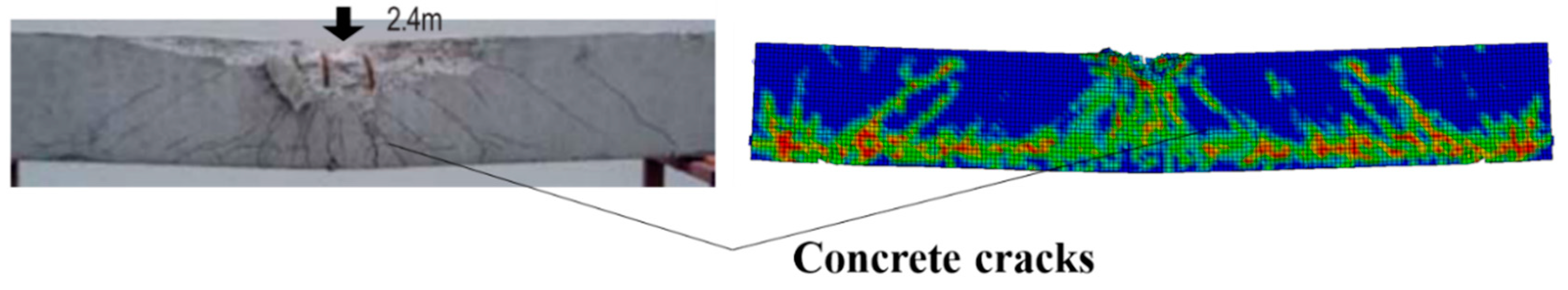
3.3. Result Analysis

Figure 4 shows the failure behavior and damage mode of the reinforced concrete beam at the impact velocity of 6.86 m/s and compares the results of the finite element simulation with the experimental results. The results showed that localized damage occurred on the concrete impact surface. Diagonal concrete cracks appeared at the bottom of the beam, and flexural-shear failure occurred. By observing the damage range of the structure, we found that the finite element numerical calculation results are in good agreement with the experimental results.

4. Numerical Results of I-Shaped RC Beams under Combined Loads

In order to more accurately evaluate the failure behavior of I-shaped RC beams used in highway bridges under combined blast and impact loads, some parameters of the numerical model of the I-shaped RC beams were adjusted according to the design documents. The section of the model was the same as that of the experimental beam subjected to contact explosion, the span of the beam was changed to 2000 mm, the spacing of the transverse reinforcement was 100 mm, and the grid size of the structure was 10 mm. The explicit dynamic analysis software LS-DYNA was used to establish a numerical model and calculate. The detailed dimensions of the structure are shown in Figure 5. When the blast load was applied to the structure, the detonation point was 400 mm above the mid-span, and the explosive was TNT (Trinitrotoluene). Different weights of explosives can change the proportional distance Z of the explosion. When the impact load was applied to the structure, the drop weight was applied at the mid-span with a mass of 400 kg. The different initial velocities of the drop weight can reflect the height when the drop weight falls. The material model, contacts, and algorithms were the same as when the structure was subjected to a single load application. By setting the start and end time of the load., it can be realized that when the subsequent load starts to be applied to the structure, the previous load ends.

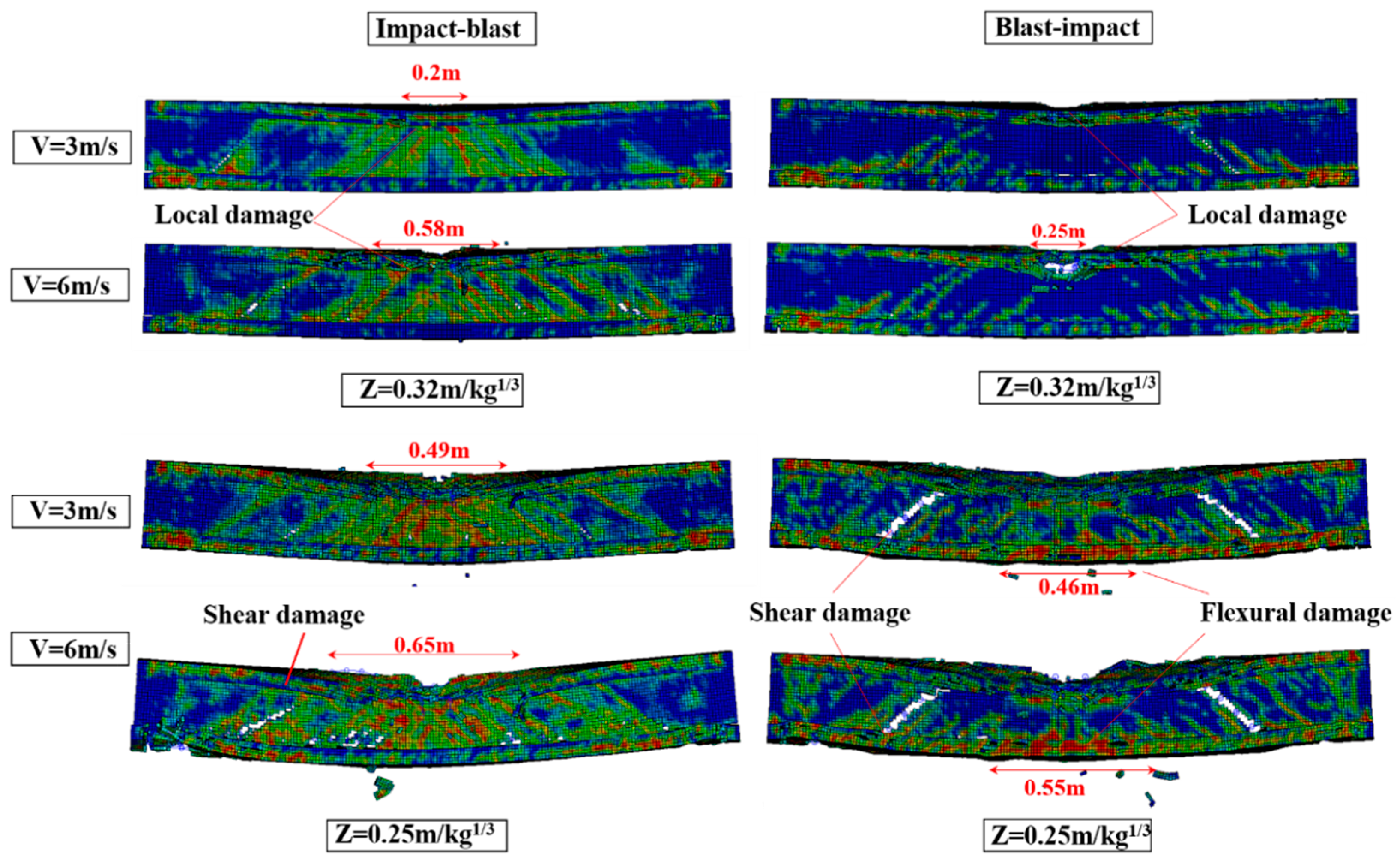
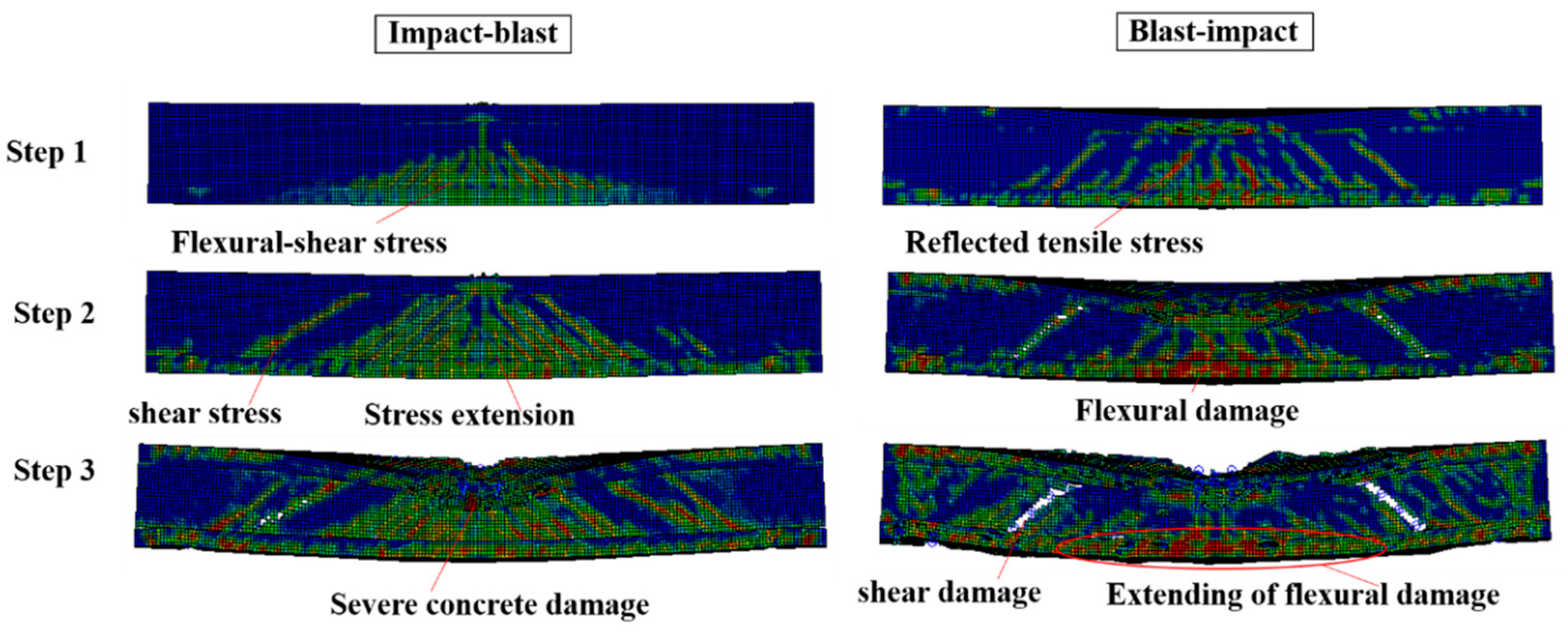
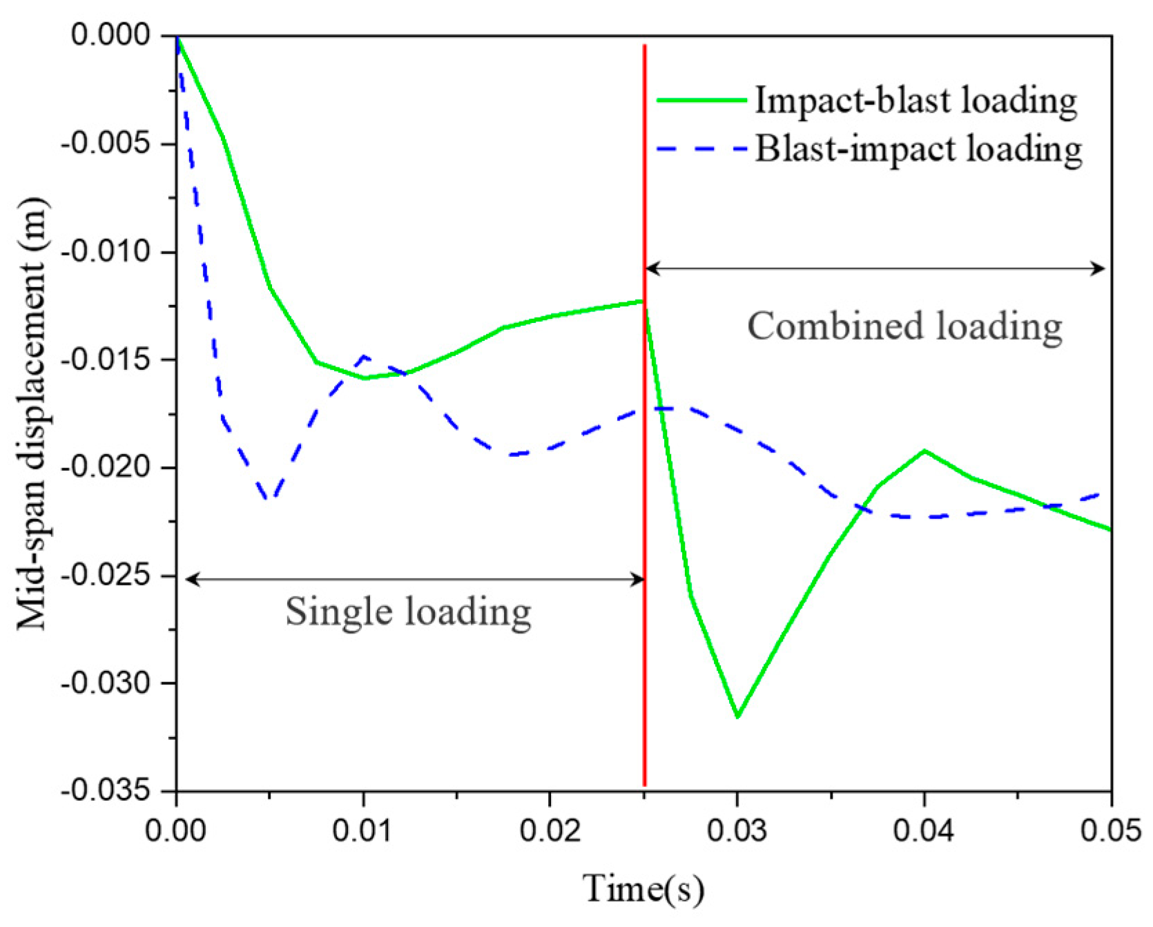
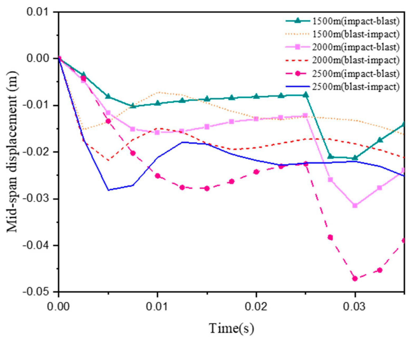
4.1. Influences of Different Load Application Sequences

By varying the start and end times of the blast and impact loads, the effects of different load sequences on the dynamic response of the structure were studied. When impact loads are applied to the structure prior to blast loads, they are called “impact–blast” loads. When blast loads are applied to the structure prior to impact loads, they are called “blast–impact” loads.
Figure 6 shows the effects of different explosion proportional distances (Z), impact velocities (V), and load loading sequences on the failure behavior of the structure. The results show that under the impact–blast load, the concrete was more severely damaged in the depth direction, and the damage location was mainly concentrated in the mid-span. The damage to the concrete in the depth direction increased with the decrease in the blast proportion and the increase in the impact velocity. However, under the blast–impact load, the concrete of the top plate was partially damaged by compression, and the concrete of the bottom plate was damaged by tension along the span direction of the beam. With the decrease in the blast proportion and the increase in the impact velocity, the overall failure mode of the beam changes from local damage to flexural-shear failure.
Figure 7 shows the structural damage changes during the load application. The main reason for the different structural dynamic responses is the different mechanism of the load. The impact load is applied to the structure in the form of concentrated force, which tends to cause obvious local flexural-shear stress in the impact zone. When the subsequent blast load is applied to the structure, it causes the spread of combined stresses. However, when the blast load is first applied to the structure, the uniform load will not cause local stress concentration, and the beam will undergo overall flexural and shear failure. The structure still has a strong bearing capacity when subjected to the subsequent impact loads. Damage along the span direction occurs in the tensile zone of the concrete. Figure 8 shows the time–history curve of the mid-span displacement of the beam under the explosion proportional distance of 0.32 m/kg1/3 and the impact velocity of 6 m/s. It can be seen that the maximum mid-span displacement of the beam under the impact–explosion load is greater than the blast–impact load, only blast, and only impact.

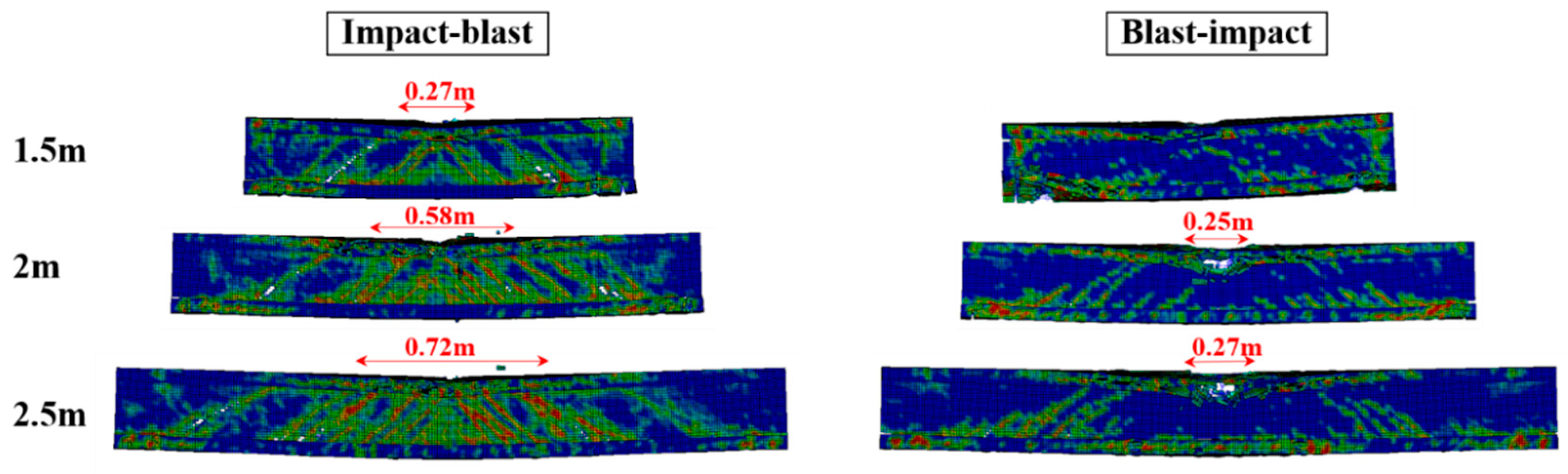
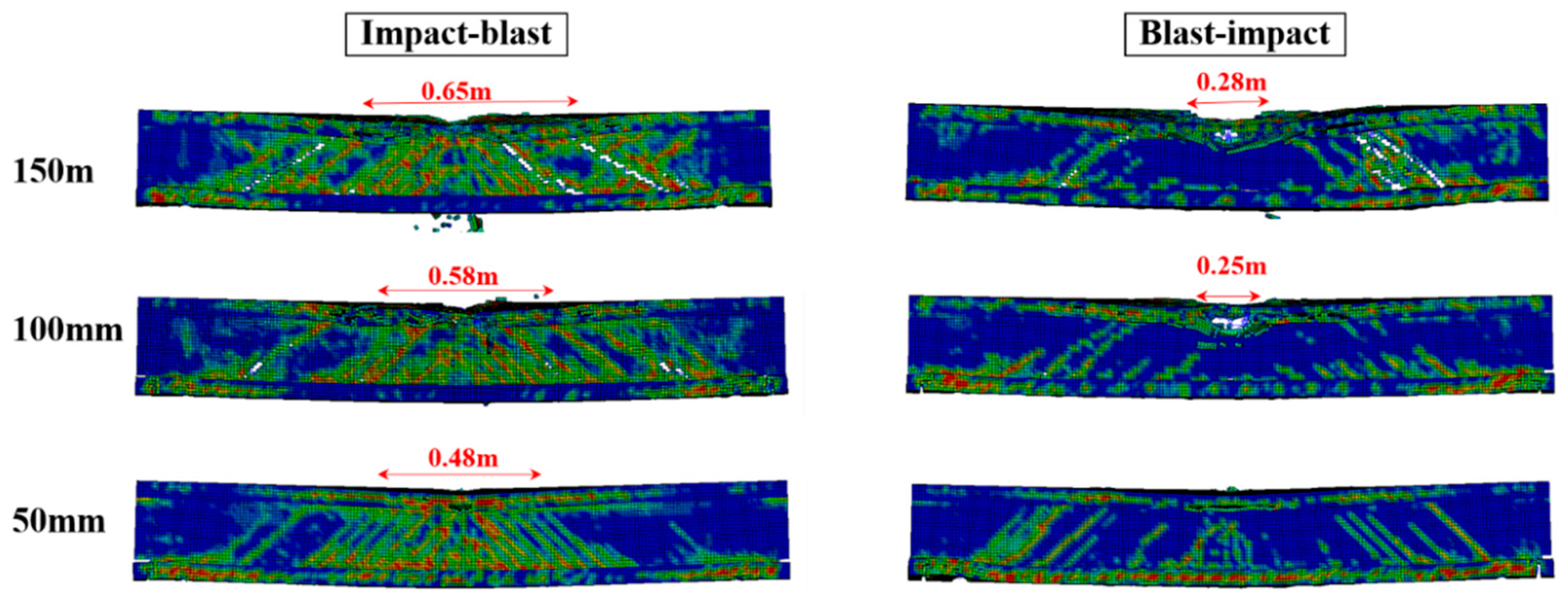
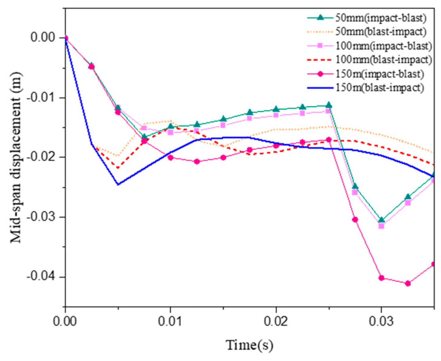
4.2. Influences of Different Beam Spans

In this section, the influence of different beam spans on the damage behavior of structures under combined blast and impact loads is discussed. When the proportional distance of the explosion is 0.32 m/kg1/3 and the impact velocity is 6 m/s, the dynamic responses of the I-shaped RC beams with spans of 1.5 m, 2 m and 2.5 m are numerically calculated, respectively. Figure 9 shows the structural damage states of the beams with different spans under the two loading conditions. The results show that with the increase in the beam span, the damage area of the concrete increases obviously. This is due to the fact that the increased span results in more flexural moments in the mid-span of the beam. At the same time, we can also see that the damage changes of the structure are more obvious under the impact–blast load. As the beam span increases, the cumulative effect of flexural-shear stress from the impact loads and stress diffusion from blast loads increases. The longer the span of the beam, the more severe the concrete failure in the depth direction of the beam. Figure 10 shows the mid-span displacement time histories of beams at different spans. It can be seen that as the beam span increases, the maximum mid-span displacement also increases. When the impact–blast load is applied to the structure, the effect of the different beam span lengths on the maximum mid-span displacement is more sensitive than when the blast–impact load is applied to the structure.

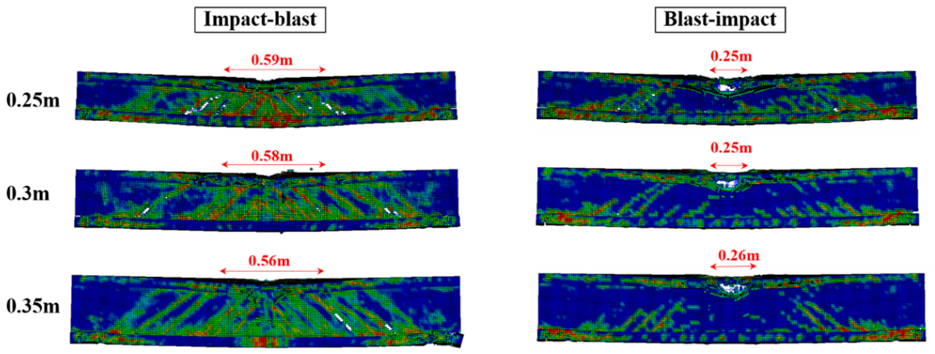
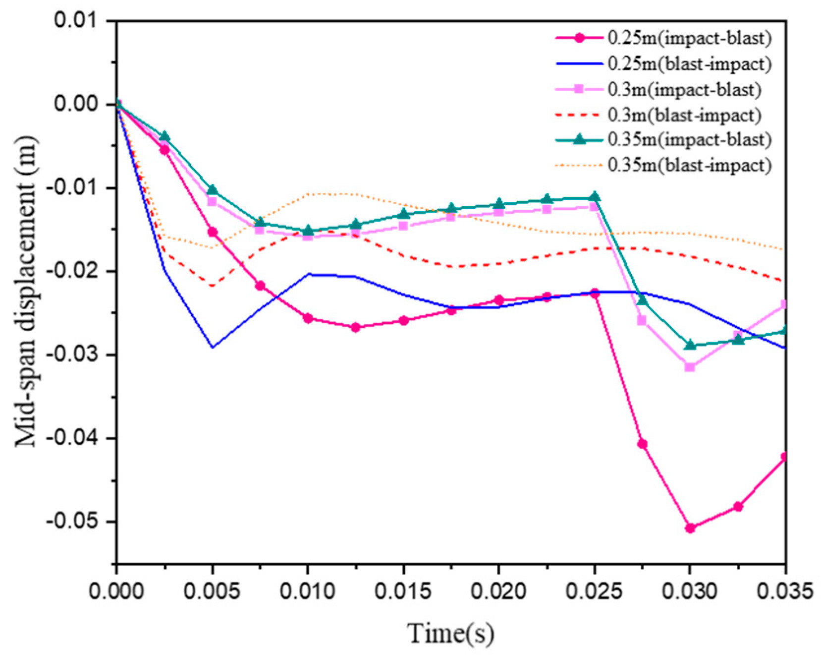
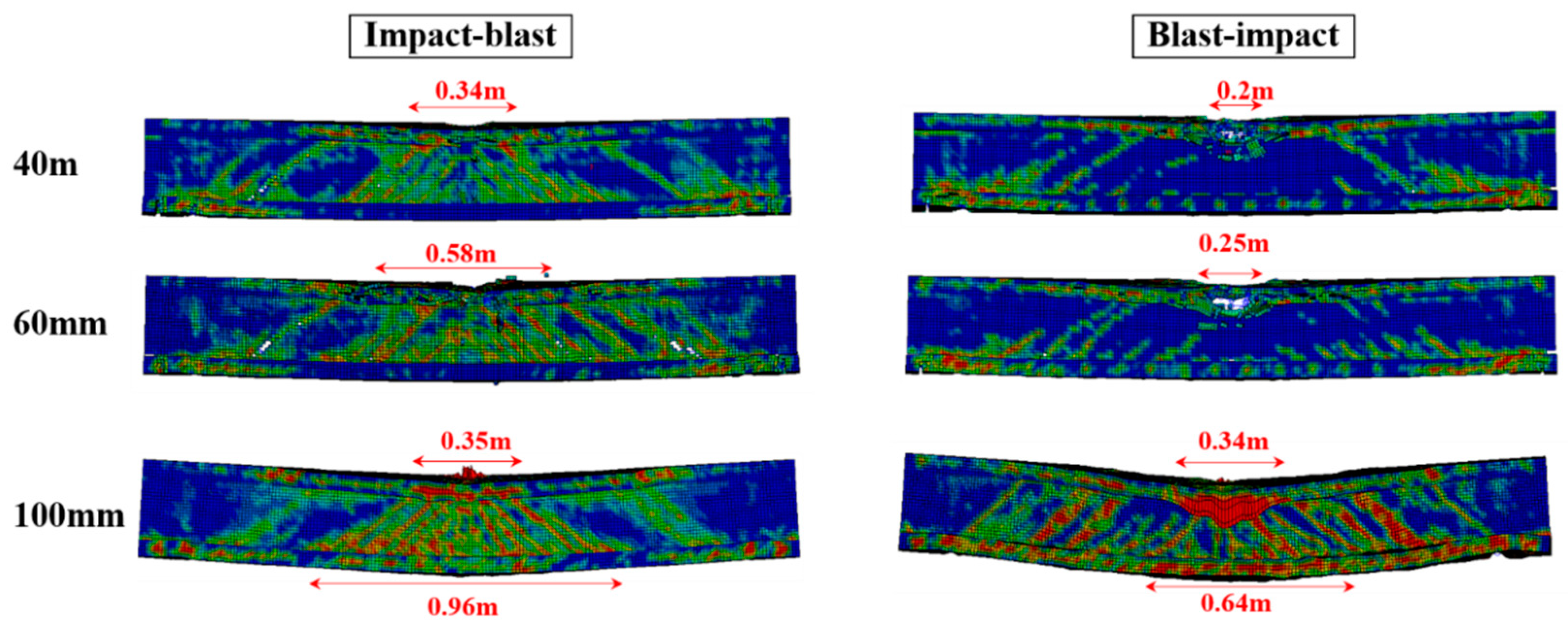
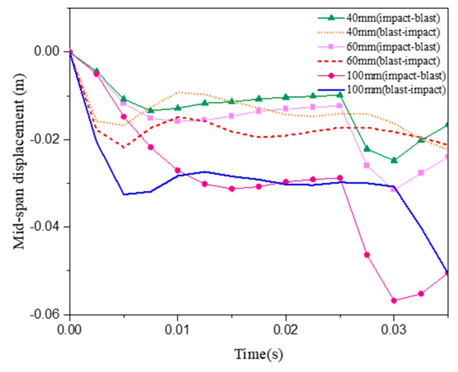
4.3. Influences of Different Beam Depths

Taking the beam depth as another structural parameter, the dynamic response and failure behavior of the structure under combined loads were studied under different beam depths. The explosion proportional distance was set to 0.32 m/kg1/3 and the impact velocity to 6 m/s. When the depth of the I-shaped RC beam was 0.25 m, 0.3 m and 0.35 m, the damage states of the structure and mid-span displacements were numerically calculated. Figure 11 shows the damage states of beams under combined loads of different beam depths. From the numerical results, it can be seen that with the increase in the beam depth, the damage degree of the concrete in the direction of the beam depth decreased, and the damage changes of the structure under the impact–blast load were more obvious. This is because when the beam depth is small, the distance between the concrete compression zone of the top plate and the concrete tension zone of the bottom plate decreases, and the overall bearing capacity of the structure decreases. However, the overall concrete damage range of the structure did not increase significantly. Figure 12 shows the time histories of the midspan displacement of the beam at different depths. It can be seen that as the beam depth increases, the maximum mid-span displacement decreases. When the structure was subjected to impact–blast loads, the influence of different beam depths on the maximum mid-span displacement was more sensitive than when the structure was subjected to blast–impact loads.

4.4. Influences of Different Longitudinal Reinforcement Spacing

By changing the longitudinal reinforcement spacing, the effect of different longitudinal reinforcement ratios on the damage behavior of the structure under combined load was studied. The explosion proportional distance was set to 0.32 m/kg1/3 and the impact velocity to 6 m/s. The dynamic response and failure behavior of the structure were studied when the longitudinal reinforcement spacing of I-shaped RC beams was 40 m, 60 mm and 100 mm, respectively. Figure 13 shows the damage states of the beams under combined loads of different longitudinal reinforcement spacing. Figure 14 shows the time-history curves of the mid-span displacement of the beams under different longitudinal reinforcement spacing. Numerical results show that the damage area and mid-span displacement of the structure increase significantly with the increase in the longitudinal reinforcement spacing no matter under impact–blast load or blast–impact load. Due to the increase in the reinforcement ratio of the longitudinal reinforcement, the flexural bearing capacity of the structure was improved. Concrete damage in the tension zone was significantly reduced. This shows that adding longitudinal reinforcement can significantly improve the ability of the structure to endure combined loads.

4.5. Influences of Different Transverse Reinforcement Spacing

By changing the transverse reinforcement spacing, the effect of different longitudinal reinforcement ratios on the damage behavior of the structure under combined load was studied. The explosion proportional distance was set to 0.32 m/kg1/3 and the impact velocity to 6 m/s. The dynamic response and failure behavior of the structure were studied when the transverse reinforcement spacing of I-shaped RC beams was 50 m, 100 mm, and 150 mm respectively. Figure 15 shows the damage states of the beams under the combined loads of the different transverse reinforcement spacing. Figure 16 shows the time–history curves of the mid-span displacement of beams under the different transverse reinforcement spacing. The results show that the damage area and mid-span displacement of the structure decrease significantly with the increase in the transverse reinforcement ratio, no matter under the impact blasting load or the blasting impact load. The increase in the transverse reinforcement can greatly improve the shear resistance of the structure, and the damage area of the concrete caused by the shear force is reduced. Increasing the reinforcement ratio of the transverse reinforcement is of great significance to improving the ability of the structure to endure the combined load.

5. Conclusions

In this paper, the I-shaped RC beam widely used in highway bridges was taken as the analysis object, and the explicit dynamic analysis software LS-DYNA was used to numerically analyze the dynamic response and failure behavior of the structure under combined blast and impact loads. There is no relevant research on this type of structure in the existing literature. To this end, we carried out explosion experiments on the I-shaped RC beams, obtained an effective numerical model, and carried out numerical calculations under combined loads. It was found that different loading sequences have an important influence on the dynamic response of the structure. When the impact load was first applied to the structure, more severe concrete damage and larger mid-span displacements occurred in the depth direction of the beam. However, when the blast load was first applied to the structure, the concrete in the span direction of the beam was damaged in a longer range, while the large-scale concrete spalling in the depth direction of the beam did not occur. This was mainly due to the different mechanisms of blast and impact loads. When the impact load was applied to the structure in the form of concentrated force, the impact area will easily form local flexural-shear stress, and the subsequent explosion load will cause the combined stress to spread. The application mechanism of blast load was uniform load, and the structure will not form obvious local stress before being subjected to impact load. The concrete tension zone has the greater resistance to cracking.
In addition, a parametric analysis was carried out, including some important structural parameters such as span, depth, and reinforcement configuration. It was found that the maximum mid-span displacement of the beam decreases when the beam span decreases or the beam depth increases. However, when the reinforcement ratio of longitudinal or transverse reinforcement increases, the maximum mid-span displacement of the beam decreases. It is worth noting that the loading sequences of the different combined loads have different sensitivities to the structural parameters. When the span, depth, transverse reinforcement ratio, and longitudinal reinforcement ratio change within a certain range, the maximum mid-span displacement changes are 52.08%, 42.31%, 39.66%, and 47.62%, respectively, under the impact–blast load. Under the blast–impact load, the displacement changes are 37.93%, 36.67%, 54.35%, and 16.00%, respectively. Therefore, the structure is more sensitive to changes in the structural parameters when it is first subjected to impact loads.
Based on the above research, the work that can be continued in the future is as follows:
(1) Empirical formula of residual capacity: through the restart function of the finite element software LS-DYNA, apply a flexural moment to the structure after the combined loads to obtain the residual capacity of the structure. According to the parameter analysis, the empirical formula is obtained.
(2) Dynamic analysis of I-shaped composite girder bridges: establish a numerical analysis model for I-shaped composite girder bridges. Based on the dynamic response of the components under the combined loads, the dynamic response or collapse analysis of I-shaped composite girder bridges is further studied.
(3) Different types of combined loads: In addition to the extreme loads of blast and impact, bridge structures may still face other forms of combined loads. For example, when a tanker truck explodes, the structure may be subjected to both blast and fire loads.

Author Contributions

All authors significantly contributed to the scientific study and writing. J.L. and Y.Y. contributed to the overall idea, model formulation and analysis; J.L. contributed to the writing of the manuscript; Y.L. contributed to the process of refining research ideas. All authors have read and agreed to the published version of the manuscript.

Funding

This research received no external funding.

Institutional Review Board Statement

The study did not require ethics approval and the authors chose to exclude this statement.

Informed Consent Statement

The study did not involve humans and the authors chose to exclude this statement.

Data Availability Statement

The data that support the findings of this study are available from the corresponding author upon reasonable request.

Conflicts of Interest

The authors declare no conflict of interest.

References

  1. Ma, L.; Wu, H.; Fang, Q. Damage Mode and Dynamic Response of RC Girder Bridge Under Explosions. Eng. Struct. 2021, 243, 112676. [Google Scholar] [CrossRef]
  2. Yao, S.; Zhang, D.; Chen, X.; Lu, F.; Wang, W. Experimental and Numerical Study on the Dynamic Response of RC Slabs under Blast Loading. Eng. Fail. Anal. 2016, 66, 120–129. [Google Scholar] [CrossRef]
  3. Ning, J.; Yang, S.; Ma, T.; Xu, X. Fragment Behavior of Concrete Slab Subjected to Blast Loading. Eng. Fail. Anal. 2022, 138, 106370. [Google Scholar] [CrossRef]
  4. Lyu, P.; Fang, Z.; Wang, X.; Huang, W.; Zhang, R.; Sang, Y.; Sun, P. Explosion Test and Numerical Simulation of Coated Reinforced Concrete Slab Based on BLAST Mitigation Polyurea Coating Performance. Materials 2022, 15, 2607. [Google Scholar] [CrossRef]
  5. Zhao, C.; Ye, X.; He, K.; Gautam, A. Numerical Study and Theoretical Analysis on Blast Resistance of Fabricated Concrete Slab. J. Build. Eng. 2020, 32, 101760. [Google Scholar] [CrossRef]
  6. Tahzeeb, R.; Alam, M.; Muddassir, S.M. A Comparative Performance of Columns: Reinforced Concrete, Composite, and Composite with Partial C-FRP Wrapping under Contact Blast. Mater. Today 2022, 62, 2191–2202. [Google Scholar] [CrossRef]
  7. Tahzeeb, R.; Alam, M.; Muddassir, S.M. Performance of composite and tubular columns under close-in blast loading: A comparative numerical study. Mater. Today 2022, 65, 51–62. [Google Scholar] [CrossRef]
  8. Shi, Y.; Hu, Y.; Chen, L.; Li, Z.; Xiang, H. Experimental Investigation into the Close-in Blast Performance of RC Columns with Axial Loading. Eng. Struct. 2022, 268, 114688. [Google Scholar] [CrossRef]
  9. Fujikake, K.; Aemlaor, P. Damage of Reinforced Concrete Columns Under Demolition Blasting. Eng. Struct. 2013, 55, 116–125. [Google Scholar] [CrossRef]
  10. Fujikura, S.; Bruneau, M.; Lopez-Garcia, D. Experimental Investigation of Multihazard Resistant Bridge Piers Having Concrete-Filled Steel Tube under Blast Loading. J. Bridg. Eng. 2008, 13, 586–594. [Google Scholar] [CrossRef]
  11. Yao, S.; Zhang, D.; Lu, F.; Wang, W.; Chen, X. Damage Features and Dynamic Response of RC Beams under Blast. Eng. Fail. Anal. 2016, 62, 103–111. [Google Scholar] [CrossRef]
  12. Fan, Y.; Chen, L.; Fang, Q.; Wang, T. Blast Resistance of Externally Prestressed RC Beam: A Theoretical Approach. Eng. Struct. 2019, 179, 211–224. [Google Scholar] [CrossRef]
  13. Liu, S.; Zhou, Y.; Zhou, J.; Zhang, B.; Jin, F.; Zheng, Q.; Fan, H. Blast Responses of Concrete Beams Reinforced with GFRP Bars: Experimental Research and Equivalent Static Analysis. Compos. Struct. 2019, 226, 111271. [Google Scholar] [CrossRef]
  14. Algassem, O.; Li, Y.; Aoude, H. Ability of Steel Fibers to Enhance the Shear and Flexural Behavior of High-strength Concrete Beams Subjected to Blast Loads. Eng. Struct. 2019, 199, 109611. [Google Scholar] [CrossRef]
  15. Liu, Y.; Yan, J.; Huang, F. Behavior of Reinforced Concrete Beams and Columns Subjected to Blast Loading. Def. Technol. 2018, 14, 550–559. [Google Scholar] [CrossRef]
  16. Fujikake, K.; Li, B.; Soeun, S. Impact Response of Reinforced Concrete Beam and Its Analytical Evaluation. J. Struct. Eng. 2009, 135, 938–950. [Google Scholar] [CrossRef]
  17. Li, H.; Chen, W.; Pham, T.M.; Hao, H. Analytical and Numerical Studies on Impact Force Profile of RC Beam under Drop Weight Impact. Int. J. Impact. Eng. 2021, 147, 103743. [Google Scholar] [CrossRef]
  18. Cheng, J.; Wen, H. Effect of Impact Velocity on the Failure Modes of A RC Beam. Int. J. Impact. Eng. 2022, 160, 104061. [Google Scholar] [CrossRef]
  19. Almusallam, T.; Abadel, A.; Siddiqui, N.; Abbas, H.; Al-Salloum, Y. Impact Behavior of Hybrid-fiber Reinforced Concrete Beams. Structures 2022, 39, 782–792. [Google Scholar] [CrossRef]
  20. Pham, T.T.; Kurihashi, Y.; Masuya, H. Performance of Reinforced Concrete Beam with Cushion Subjected to Impact Loading. Case. Stud. Constr. Mat. 2022, 16, e00893. [Google Scholar] [CrossRef]
  21. Fan, W.; Xu, X.; Zhang, Z.; Shao, X. Performance and Sensitivity Analysis of UHPFRC–strengthened Bridge Columns Subjected to Vehicle Collisions. Eng. Struct. 2018, 173, 251–268. [Google Scholar] [CrossRef]
  22. Gholipour, G.; Zhang, C.; Mousavi, A.A. Effects of Axial Load on Nonlinear Response of RC Columns Subjected to Lateral Impact Load: Ship-pier Collision. Eng. Fail. Anal. 2018, 91, 397–418. [Google Scholar] [CrossRef]
  23. Zhang, C.; Gholipour, G.; Mousavi, A.A. Nonlinear Dynamic Behavior of Simply-supported RC Beams Subjected to Combined Impact-blast loading. Eng. Struct. 2019, 181, 124–142. [Google Scholar] [CrossRef]
  24. Murray, Y.D. Users Manual for LS-DYNA Concrete Material Model 159; Report No. FHWA-HRT-05-062; Federal Highway Administration: Washington, DC, USA, 2007; pp. 3–13.
  25. Béton CE-Id. CEB-FIP Model Code 1990: Design Code; Thomas Telford: London, UK, 1993. [Google Scholar]
  26. Malvar, L.J.; Crawford, J.E. Dynamic Increase Factors for Concrete; DTIC Document: Fort Belvoir, VA, USA, 1998. [Google Scholar]
  27. Malvar, L.J.; Crawford, J.E. Dynamic Increase Factors for Steel Reinforcing Bars. In Proceedings of the 28th DDESB Seminar, Orlando, FL, USA, 8–9 August 1998. [Google Scholar]
Figure 1. Geometric model of I-shaped RC beam; (a) experimental model, and (b) numerical model.
Applsci 13 01943 g001
Figure 2. Damage behavior and numerical analysis results of the I-shaped RC beam under the blast load.
Applsci 13 01943 g002
Figure 3. Numerical analysis model of the RC beam.
Applsci 13 01943 g003
Figure 4. Damage behavior and numerical analysis results of the RC beam under the impact load.
Applsci 13 01943 g004
Figure 5. Numerical analysis model of I-shaped RC beam under combined load.
Applsci 13 01943 g005
Figure 6. Numerical analysis results of damage behavior of I-shaped RC beams under different impact rates and proportional distances.
Applsci 13 01943 g006
Figure 7. Damage states of the beam progressing under different combined loadings with V = 6.86 m/s and Z = 0.32 m/kg1/3.
Applsci 13 01943 g007
Figure 8. Time-history curves of mid-span displacement of beams under different loading sequences.
Applsci 13 01943 g008
Figure 9. Damage states of beams under combined loads of different beam spans.
Applsci 13 01943 g009
Figure 10. Time-history curves of mid-span displacement of beams under different beam spans.
Applsci 13 01943 g010
Figure 11. Damage states of beams under combined loads of different beam depths.
Applsci 13 01943 g011
Figure 12. Time-history curves of mid-span displacement of beams under different beam depths.
Applsci 13 01943 g012
Figure 13. Damage states of beams under combined loads of different longitudinal reinforcement spacing.
Applsci 13 01943 g013
Figure 14. Time-history curves of mid-span displacement of beams under different longitudinal reinforcement spacing.
Applsci 13 01943 g014
Figure 15. Damage states of beams under combined loads of different transverse reinforcement spacing.
Applsci 13 01943 g015
Figure 16. Time-history curves of mid-span displacement of beams under different transverse reinforcement spacing.
Applsci 13 01943 g016
Table 1. Material properties used for I-shaped RC beams under blast loads.
ModelParameterValue
ConcreteMass density (kg/m3)2350
Compressive strength (MPa)49.6
Rate effectsTurn on
Rebar (longitudinal and transverse)Failure strain0.14
Poisson’s ratio0.3
Strain rate parameter C40
Strain rate parameter p5.0
Transverse rebarYoung’s modulus (GPa)195.6
Yield stress (MPa)320.3
Longitudinal rebarYoung’s modulus (GPa)205.4
Yield stress (MPa)410.6
Table 2. Material properties used for I-shaped RC beams under impact loads.
ModelParameterValue
ConcreteMass density (kg/m3)2440
Compressive strength (MPa)42
Rate effectsTurn on
Rebar (longitudinal and transverse)Young’s modulus (GPa)210
Failure strain0.14
Poisson’s ratio0.3
Strain rate parameter C40
Strain rate parameter p5.0
Transverse rebarYield stress (MPa)295
Longitudinal rebarYield stress (MPa)418
Disclaimer/Publisher’s Note: The statements, opinions and data contained in all publications are solely those of the individual author(s) and contributor(s) and not of MDPI and/or the editor(s). MDPI and/or the editor(s) disclaim responsibility for any injury to people or property resulting from any ideas, methods, instructions or products referred to in the content.

