1. Introduction
Precision cylindrical rollers, characterized by their diminutive dimensions and lightweight composition, present challenges in dynamic unbalance detection, specifically in terms of driving difficulties and susceptibility to surface damage. With the progress of science and technology, the requisites for cylindrical roller bearings in contemporary industries have seen a marked escalation. This trend is particularly pronounced in high-precision equipment, where bearings must exhibit the capacity to withstand both high speeds and impacts while sustaining exceptional dynamic characteristics and protracted service life during high-speed operation. The inherent disparities in material distribution and shape asymmetry in small-scale, high-speed precision cylindrical rollers introduce a discernible deviation between the central main inertia axis and the axis of rotation. Consequently, this engenders dynamic unbalance in the cylindrical roller’s operation [
1,
2]. The presence of dynamic unbalance in a cylindrical roller during high-speed rotation begets periodic centrifugal forces [
3,
4,
5]. The larger centrifugal forces induce an alteration in the force equilibrium of the cylindrical roller, thereby exacerbating rotational slippage and spin sliding phenomena [
6]. These effects hasten the surface wear of the cylindrical roller, consequently leading to a decline in the performance, operational lifespan, and overall efficiency of rotating machinery [
7]. Consequently, it is imperative that, prior to the assembly of bearings, a thorough assessment of dynamic unbalance in the rollers is conducted, allowing for the identification and subsequent selection of rollers that adhere to permissible tolerance levels for assembly. This rigorous process serves to ensure the dependable and uninterrupted operation of the equipment.
Presently, within the industrial domain, prevalent dynamic balancing machines are predominantly tailored for large-scale rotating entities such as automobile wheel hubs, machine tool spindles, and motor rotors, characterized by substantial volume and mass. In contrast, cylindrical rollers, characterized by relatively compact dimensions and mass, present a distinct set of challenges. These include impediments to in providing sufficient support, limitations in achieving high-speed rotation, and susceptibility to surface damage during dynamic unbalance detection. In response, Cui Yong and Sui Xin et al. [
8,
9] of Henan University of Science and Technology devised a dynamic unbalance detection system for low-mass cylindrical rollers, leveraging micro-electro-mechanical systems (MEMS) technology. This system incorporates a V-block for stabilization and a belt pulley to drive the rotation of the cylindrical roller, thereby circumventing the limitations of conventional detection systems characterized by unwieldy frames, significant mass, elevated cost, and diminished sensitivity. During rotation, it is worth noting that the belt speed may lead to excessive deformation, resulting in elastic sliding. Furthermore, the pulley itself may generate interference in the form of vibration signals, while the belt and supporting V-block may also pose a risk of surface damage to the cylindrical roller. Subsequently, Cui Yongcun et al. [
10] from Northwestern Polytechnical University engineered a high-speed, negative-pressure air flotation spindle, employing negative-pressure gas for the adhesion and subsequent rotation of cylindrical rollers. This innovative approach effectively addresses the challenge of limited rotational speed in cylindrical rollers. However, it is pertinent to mention that the method of employing an air flotation spindle for the high-speed adsorption and rotation of cylindrical rollers exhibits notable drawbacks. Primarily, it displays diminished stability due to the inherent dynamic unbalance within the cylindrical rollers and the absence of radial support in the drive mechanism. Furthermore, Duan Mingde et al. [
11] from Henan University of Science and Technology introduced a non-destructive detection methodology for dynamic unbalance in cylindrical rollers. This approach employs an air flotation slide table to facilitate the rotation of the cylindrical roller, thereby preventing potential surface damage.
Building upon the research conducted by Duan Mingde and colleagues, this paper proposes a novel non-destructive driving mechanism. The structure of the paper is outlined as follows:
Section 2 introduces the structures and principles of the non-destructive driving mechanism. In
Section 3, an analysis of the force distribution on the cylindrical roller is presented, emphasizing the significance of the bearing air film based on force analysis.
Section 4 delves into the mechanical characteristics of the bearing air film by examining the internal structure of the air flotation sleeve, determining the optimal thickness for the load-bearing air film.
Section 5 describes finite element analysis of the load-bearing air film, validating the rationality of the mathematical model.
Section 6 introduces the experimental platform for non-destructive driving and discusses the experimental results. Finally,
Section 7 summarizes the main research findings and provides prospects for further studies.
2. Non-Destructive Drive Mechanism
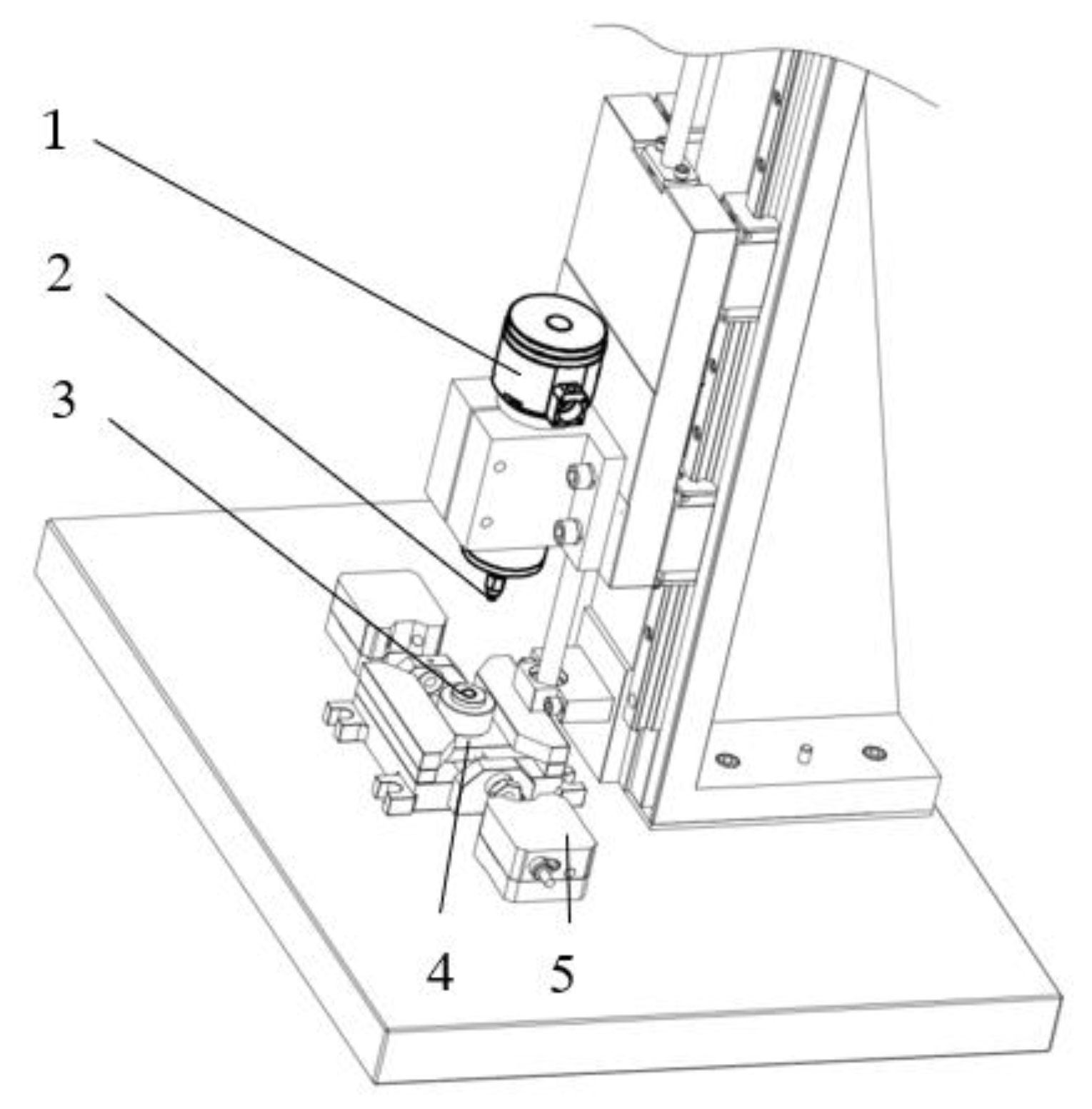
Figure 1 illustrates a novel, non-destructive detection method for dynamic unbalance of cylindrical rollers. The underlying principle is as follows: when a cylindrical roller undergoes high-speed, unimpeded rotation within an air flotation sleeve, its geometric center axis deviates from the axis coinciding with the center of mass. Consequently, this induces a periodic force acting on the air flotation sleeve. This gives rise to periodic vibrations of the air flotation slide. The amplitude of these vibrations is gauged by a sensor, and subsequently, the software algorithm derives the dynamic unbalance value of the cylindrical roller.
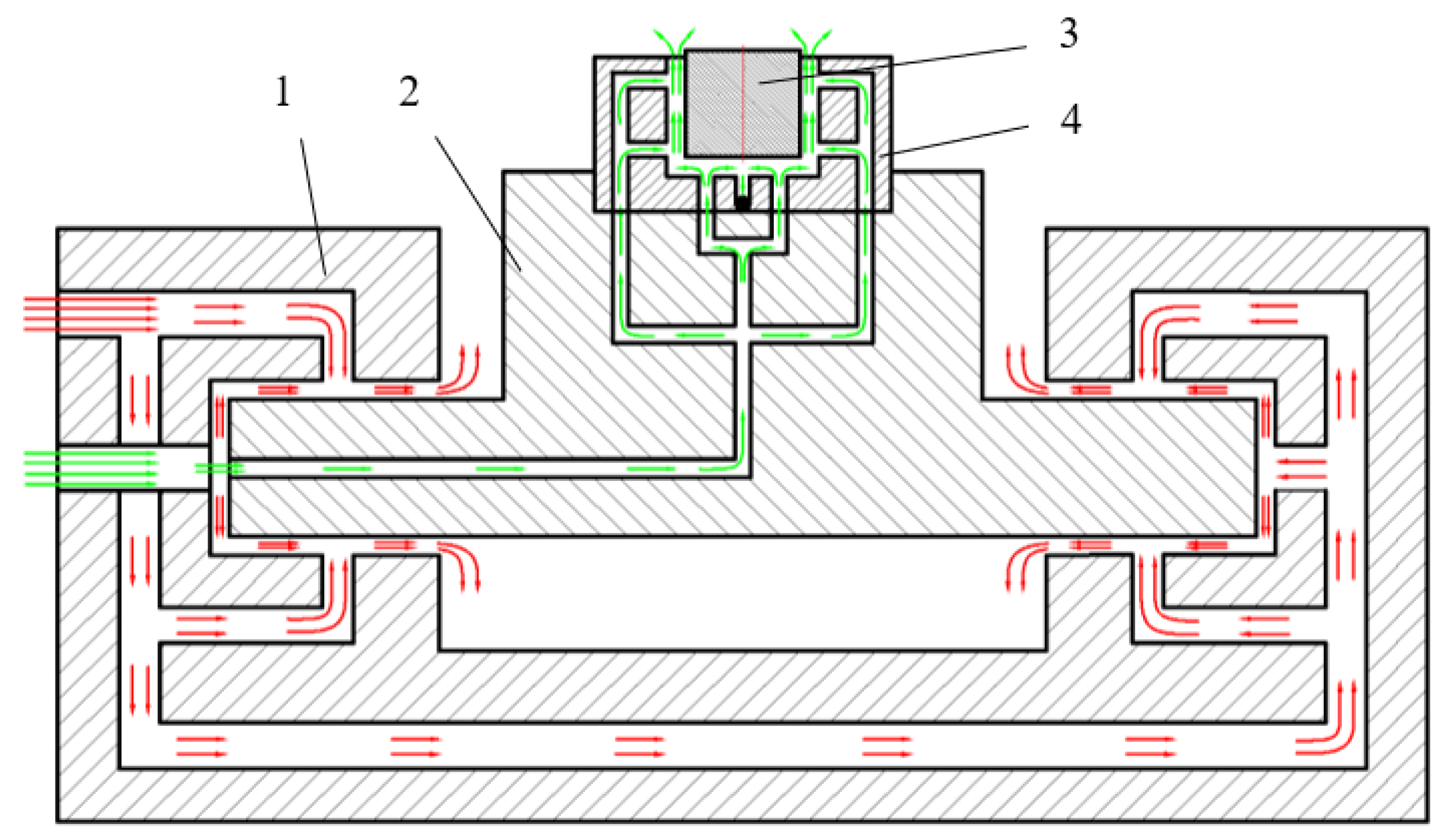
Figure 2 provides an illustrative schematic outlining the principle of non-destructive air flotation support(Red represents the air supply system for the air floatation slide, while green represents the air supply system for the air floatation sleeve).
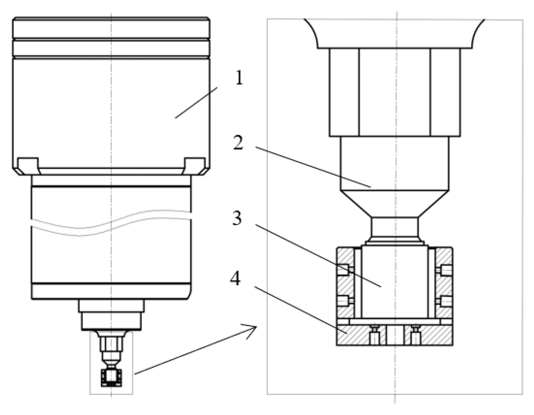
This paper introduces a novel, non-destructive drive mechanism, building upon the previously outlined non-destructive method of dynamic unbalance detection. This mechanism, illustrated in
Figure 3, comprises key components including an air flotation electrical spindle, a vacuum suction cup, a cylindrical roller, and an air flotation sleeve.
The air flotation sleeve is securely affixed to the air flotation slide, facilitating the introduction of compressed air into the sleeve and thus generating an air film [
12]. Initially, the cylindrical roller remains stationary within the air flotation sleeve, with the air film solely shouldering the roller’s self-weight. Subsequently, the electric spindle descends axially along the cylindrical roller, resulting in a reduction in air film thickness and an attendant increase in load-bearing capacity [
13,
14,
15]. The air flotation electrical spindle harnesses the static frictional force exerted by the vacuum suction cup on the upper surface of the cylindrical roller to initiate high-speed rotation. Once the predetermined speed is achieved, the electric spindle ascends, disengaging the vacuum suction cup from the upper surface of the cylindrical roller. Consequently, the cylindrical roller commences independent rotation within the air flotation sleeve, embarking on the dynamic unbalance detection process.
3. Force Analysis of Cylindrical Roller
In order to enhance detection efficiency, it is imperative for the drive mechanism to expedite the cylindrical roller to the prescribed velocity within the briefest feasible duration [
16,
17]. However, it is worth noting that excessive angular acceleration may ensue, potentially leading to undesired slippage between the vacuum suction cup and the surface of the cylindrical roller. To safeguard the integrity of the cylindrical roller’s surface, it becomes imperative that the frictional torque significantly surpass the initial starting torque requisite for mobilizing the cylindrical roller.
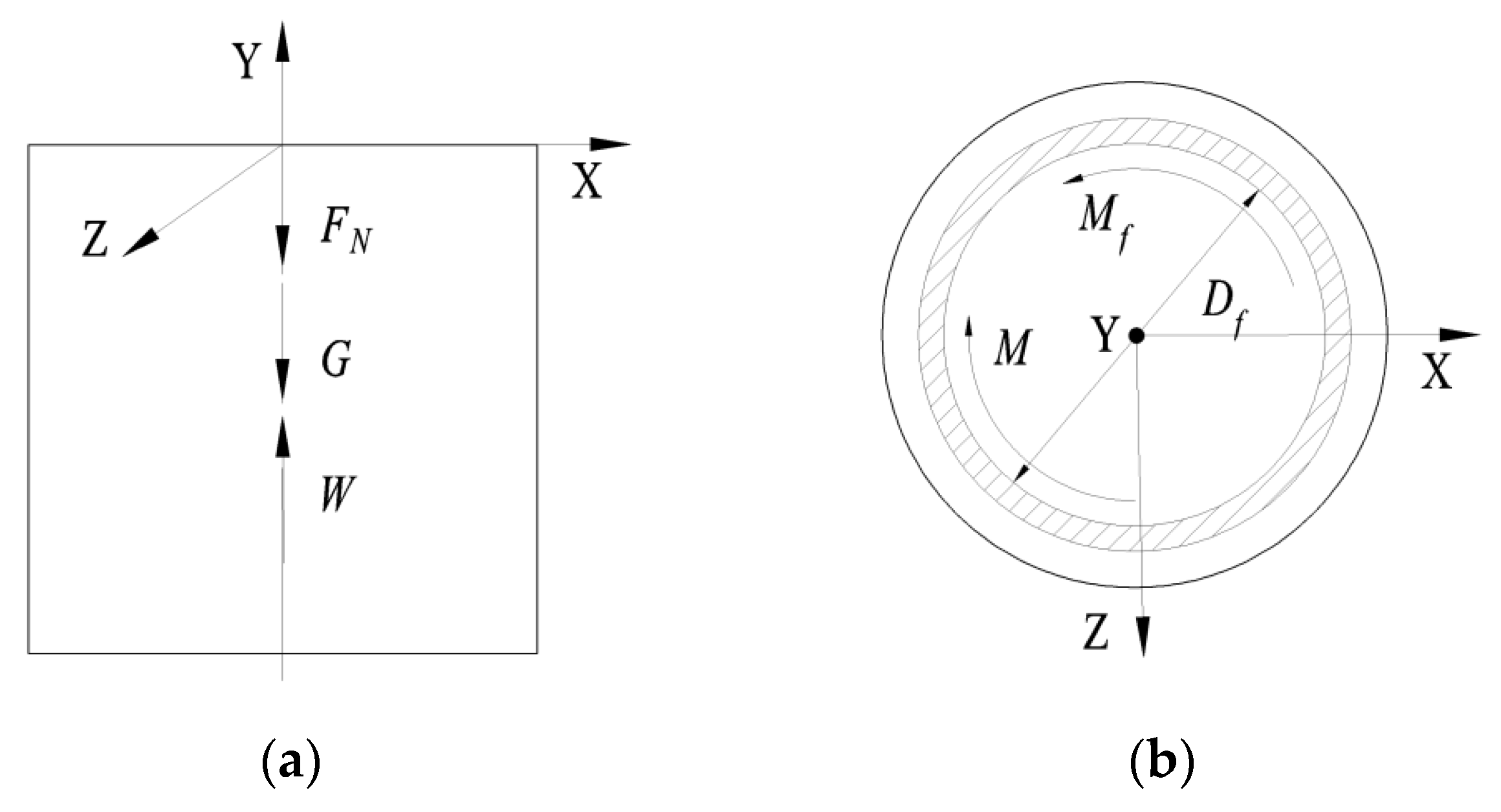
The disregard for the viscous force exerted by the air film on the cylindrical roller is warranted due to its minimal impact on the roller’s motion. During the stage of accelerated rotation, a comprehensive analysis of forces acting on the axial and upper-end facets of the cylindrical roller, termed as the contact force, is undertaken, as depicted in
Figure 4. These forces include the gravitational force
acting in the downward direction, the upward load-bearing force sustained by the air film
, and the downward force applied by the vacuum suction cup
. Furthermore, attention is directed towards the application of the starting torque
and the frictional torque
at the upper-end face of the cylindrical roller. To facilitate a rigorous examination, a Cartesian coordinate system is established. It is postulated that the equilibrium of the cylindrical roller is achieved through the concerted interplay of these forces.
The analytical equation of friction torque and starting torque is as follows.
The pertinent parameters are defined as follows: represents the friction coefficient characterizing the interaction between the vacuum suction cup and the upper surface of the cylindrical roller. signifies the effective adsorption diameter of the vacuum suction cup, while denotes the mass of the cylindrical roller. stands for the radius of the cylindrical roller, designates the predetermined maximum speed set for the cylindrical roller, and represents the duration required for the cylindrical roller to attain the specified maximum speed.
By examining Equations (1) and (2), it becomes evident that the duration necessary to accelerate the cylindrical roller to the specified velocity, without alterations to the drive’s material composition or structural configuration, hinges on the load-bearing capacity of the air film.
4. Mathematical Model of Air Film Load-Bearing Characteristics
This apparatus leverages the load-bearing phenomenon facilitated by the air film to achieve non-destructive support for the high-speed rotation of the cylindrical roller. In the context of the axial load-bearing air film for the cylindrical roller, established principles in fluid mechanics dictate that a decrease in air film thickness corresponds to an augmentation in load-bearing capacity. However, due to inherent geometric imperfections present on the upper and lower end surfaces of both the cylindrical roller and the vacuum suction cup, operational forces may induce vertical oscillations. In severe instances, this oscillation may culminate in contact between the lower end surface of the cylindrical roller and the base of the air flotation sleeve, resulting in detrimental effects on the end surface of the cylindrical roller. As an industry-wide practice, the thickness of the load-bearing air film is typically maintained at several tens of microns, a dimension that ensures maximal stiffness of the air film [
18].
Regarding the radial load-bearing air film supporting the cylindrical roller, as explicated in the preceding sections, the non-destructive dynamic unbalance detection method outlined in this paper necessitates the generation of a cyclic force exerted by the cylindrical roller onto the air flotation sleeve. To optimize both the lubrication and load-bearing functions of this radial load-bearing air film, it is imperative to maximize its rigidity.
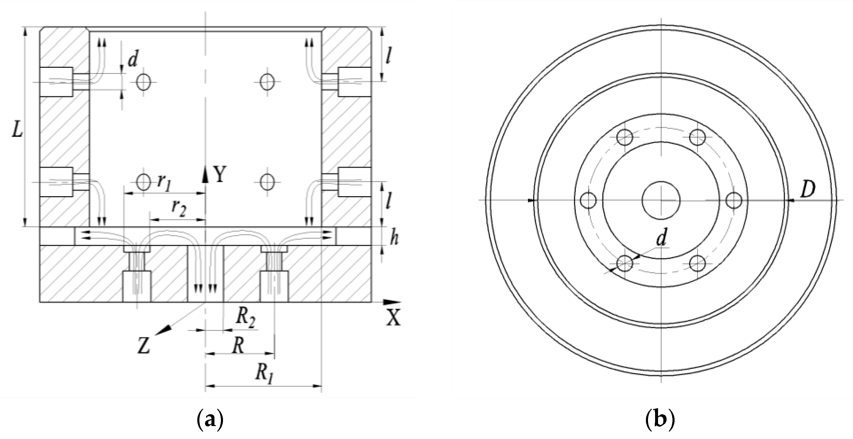
Figure 5 illustrates the configuration of the air flotation sleeve and the gas flow dynamics. Upon the introduction of external compressed air into the interstice between the air flotation sleeve and the cylindrical roller, it engenders the creation of an air film characterized by a pressure distribution adhering to a specific pattern, as detailed in the references [
19,
20]. The differential pressure between the air film and the ambient atmosphere confers upon it a designated load-bearing capacity.
The pressure distribution within the gas film is typically characterized by the Reynolds equation, a derivation drawn from the fundamental gas equation of motion, the ideal gas equation of state, and the equation governing mass conservation, resolved collectively. In practical engineering, the encountered viscous flow entails intricate boundary conditions, with flow parameters within the field exhibiting temporal and spatial variation leading to mutual interactions. Hence, prior to the calculation, it becomes necessary to posit the following assumptions.
- (1)
The flow pattern within the gas film is laminar flow and conforms to Newton’s laws of motion;
- (2)
The flow of the gas film is purely viscous and incompressible, with a constant coefficient of viscosity;
- (3)
The pressure variation in the direction of the gas film thickness is neglected, and the effects of gravity, magnetism, and other bulk forces are ignored;
- (4)
The thickness of the gas film is very small and it is a single-phase medium with continuous flow;
- (5)
The gas film is isothermal in the process of flow.
Based on the above assumptions, the N-S equation is obtained after neglecting the minutiae terms:
where
is the gas film pressure;
is the gas viscosity coefficient; and
and
are the velocity of the fluid unit moving along the
x-direction and
z-direction, respectively.
The gas continuity equation is given by:
where
is the gas density,
is the velocity of the fluid unit moving along the y-direction, and
is the time.
The gas is flowing in an isothermal laminar flow, and the equation of state is:
where
is the atmospheric pressure and
is the atmospheric density.
Combining Equations (3)–(5), a simplified Reynolds equation is obtained when the gas flow state is laminar:
The air film load-bearing capacity is calculated as follows:
where
is the air film’s load-bearing capacity and
is the effective area of the air film.
Equation (6) represents a second-order partial differential expression characterizing pressure variation with respect to geometric position. Finding its analytical solution poses a considerable challenge. In the interest of algorithmic simplification, this study employs an approach described in the existing literature [
18]. This involves an assumption that the pressure distribution along the radial direction adheres to linearity, facilitating an approximation of the air film’s load-bearing capacity.
The structure of the air flotation sleeve is shown in
Figure 5. The optimum thickness of the axial air film and the corresponding load-bearing capacity are approximately calculated. Input:
, number of throttle orifice
, throttle orifice diameter
, supply pressure
. To calculate the optimal thickness of the axial air film and its corresponding load-bearing capacity, the main steps are as follows.
- 1.
are calculated. These are the gas passage coefficient, working medium coefficient, and gas film structure coefficient, respectively.
The air film flow medium is air, so .
- 2.
ε is calculated.
- 3.
According to
, the corresponding β value is found from the universal design curve (Figure 2-1, attached in the references [
18]).
- 4.
The optimal thickness of the axial air film is calculated.
where
is the flow coefficient, generally taken as 0.8,
is the cross-sectional area of the throttle orifice, and g is a constant related to
, when
.
For the radial load-bearing air film, its structural configuration and force application characteristics align with those of conventional cylindrical air bearings. As such, the optimal thickness of the radial load-bearing air film can be readily determined through a table look-up method, leveraging the general design guidelines established within the air flotation bearing industry. These guidelines, typically accounting for factors such as air film stiffness and processing feasibility, provide a comprehensive assessment. The study cited in [
18] (p. 72), specifically Tables 2–4 (b), detailing cylindrical air bearing performance calculations, facilitates this determination. Given the geometric specifications of the air flotation sleeve and the input gas parameters in this study, the optimal thickness of the radial air film (
) is readily ascertained. While this method may entail a slight reduction in precision compared to numerical solutions of differential equations through computational means, it remains sufficiently accurate for typical engineering applications.
5. Finite Element Analysis of Air Film Load-Bearing Characteristics
To validate the accuracy of the proposed mathematical model and to investigate the gas flow dynamics within the air flotation sleeve, a finite element analysis of the air film was conducted.
A representative air flotation sleeve with specifications denoted as
was selected for this purpose. The 3D fluid domain was constructed using SolidWorks and subsequently imported into Fluent for mesh generation. The physical field reference type was designated as Watertight Geometry. Inlet ports were labeled as pressure inlets, while outlet ports were denoted as pressure outlets. The surface interfacing with the cylindrical roller, where the air film came into contact, was identified as wall-force; all other surfaces were categorized as walls. Given the minuscule thickness of the air film, ranging from a few microns to a few tens of microns, a boundary layer in the direction of the film thickness was incorporated, comprising three layers. The minimum radial air film thickness was set at 0.01 mm, with a corresponding minimum mesh size of 7 × 10
−3 mm. Subsequent refinements in mesh size did not yield substantial alterations in solution outcomes. The final mesh comprised 179,802 elements, with a minimum mesh mass of 0.285, meeting the solution criteria. For the minimum axial air film thickness of 0.005 mm, the minimum mesh size was established as 5 × 10
−3 mm. Similar reductions in mesh size did not induce noteworthy changes in the solution results. The mesh for this configuration consisted of 96,859 elements, with a minimum mesh mass of 0.262, in conformity with the solution prerequisites. The resulting model following mesh generation is depicted in
Figure 6.
After the meshing is completed, the parameters and boundary conditions of the fluid analysis were set.
- (1)
The solver was set to pressure-based, the velocity formulation is set to absolute, and the time is set to steady.
- (2)
K-epsilon (2 eqn) was selected for the model, standard was chosen for the k-epsilon model parameter, standard wall functions were set for near-wall treatment, and other control factors were defaulted.
- (3)
The material of the fluid was set to ideal air; the boundary conditions of inlet pressure were set to 600,000 Pa oriented perpendicular to the inlet interface inward; and the boundary conditions of outlet pressure were set to 100,000 Pa, oriented perpendicular to the outlet cross-section outward.
- (4)
A force report definition was created, and the force was a positive pressure (N) on the wall-force surface, that is, the load-bearing force of the air film on the cylindrical roller.
- (5)
An initialization method was selected standard initialization. Execute the solution after initialization.
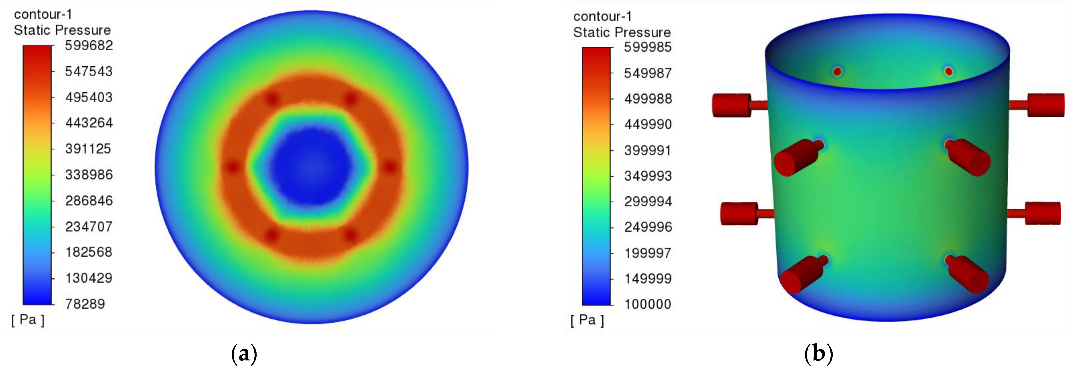
Figure 7 depicts the pressure distribution within the air film. Observably, the high-pressure zone of the axial load-bearing air film was notably concentrated in proximity to the pressure-equalizing groove. Gradually, the pressure diminished from this region towards the periphery and center, eventually reaching atmospheric levels. As for the radial load-bearing air film, the elevated pressure region primarily occupied the central expanse of the cylinder. Analogously, the pressure gradually tapered off towards atmospheric levels from this central region towards the upper and lower extremities.
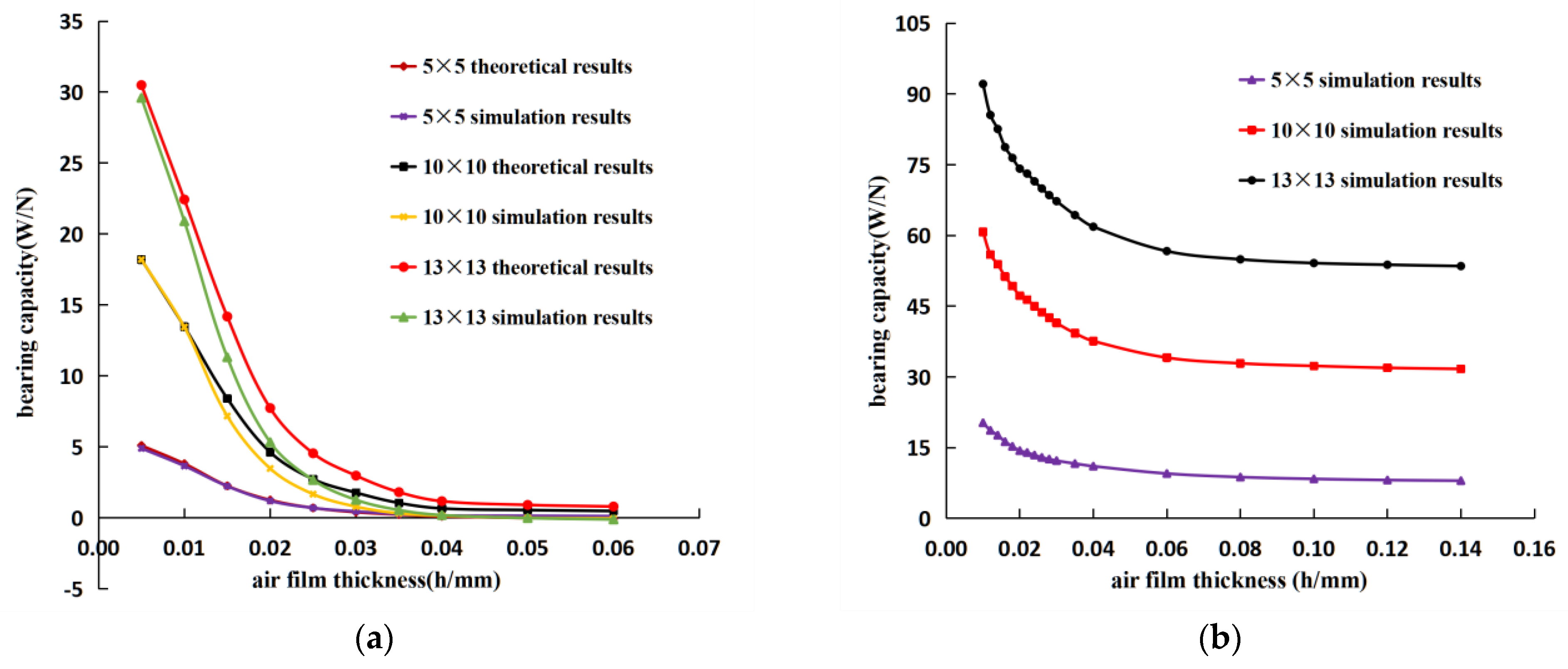
The axial and radial air film thicknesses were systematically varied as parameters, enabling a comprehensive examination and computation of the corresponding air film load-bearing capacities across different thicknesses. Additionally, two alternative configurations of air flotation sleeves were introduced for comparative analysis. Employing Fluent, a suite of simulation procedures was executed in accordance with the aforementioned protocols. The resultant data, encompassing both theoretical calculations and simulation analyses, were meticulously collated and presented in the form of scatter plots, then subsequently subjected to rigorous curve fitting for enhanced interpretative insights.
As depicted in
Figure 8, the theoretical calculations for the three specifications of the axial load-bearing air film closely aligned with the curve trends observed in the simulation results. With a progressive increment in the thickness of the axial load-bearing air film, there was a discernible decline in the air film’s load-bearing capacity, eventually approaching zero. As the thickness of the radial load-bearing air film was augmented, its load-bearing capacity gradually converged towards the force exerted by atmospheric pressure upon the cylindrical roller. These observed trends are in accordance with fundamental principles in fluid mechanics.
Error analysis: As depicted in
Figure 8a, the theoretical calculations for the 5 × 5 specification of the axial gas film exhibited a commendable concordance with the results obtained through simulation analysis. The curves exhibited a substantial overlap. However, for the 10 × 10 and 13 × 13 specifications of the axial gas film, the simulation results slightly deviated from the theoretical calculations, with the load-bearing capacity in the simulation demonstrating a negative value. This deviation arose from an enlarged outlet for the axial load-bearing gas film, resulting in an excessive outflow of gas from the outlet ports. Consequently, localized pressure levels dipped below atmospheric pressure, which was particularly evident in the central region, as illustrated in
Figure 7a. It is noteworthy that the simplified algorithm employed in theoretical calculations did not account for this phenomenon.
6. Test
To further corroborate the fidelity of the mathematical model and to substantiate the efficacy of the mechanism designed in this study for the non-destructive driving of cylindrical rollers, a functional prototype of the drive mechanism, founded upon the principle of non-destructive dynamic unbalance detection for cylindrical rollers, has been constructed.
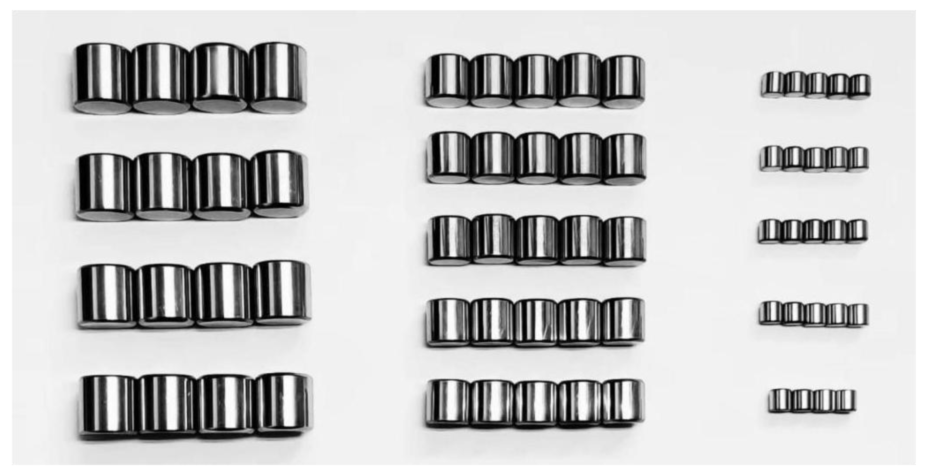
Test conditions: The specific test parameters are detailed in
Table 1, with the respective cylindrical roller specimens illustrated in
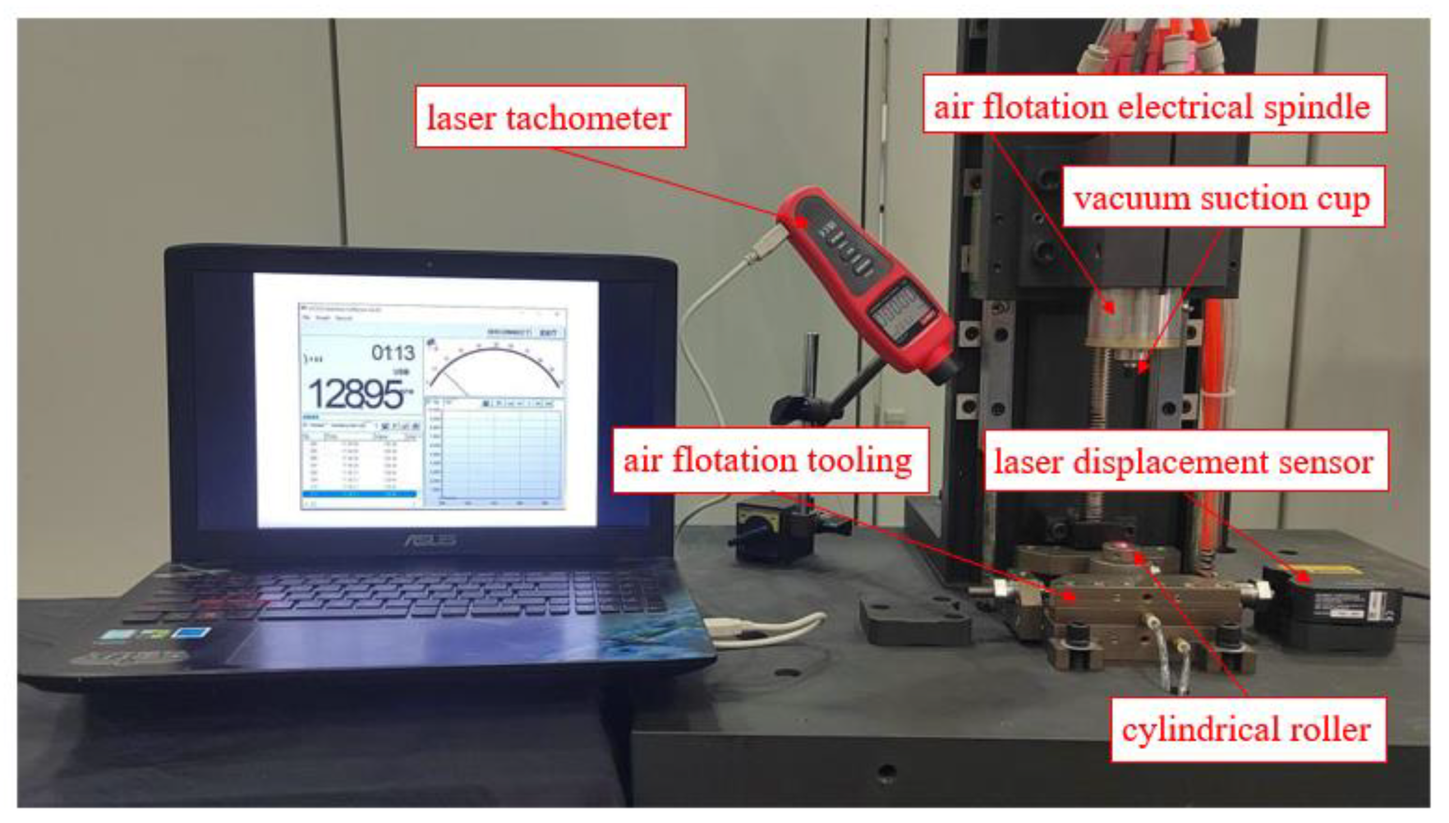
Figure 9. Each size variant of the cylindrical roller, totaling twenty pieces, was meticulously prepared for evaluation. The experimental setup, as depicted in
Figure 10 and
Figure 11, comprised essential components, including the cylindrical roller, air flotation electrical spindle, vacuum suction cup, air flotation tooling (encompassing the air flotation sleeve, slide, and guide), and the laser displacement sensor (LK-H008) and laser tachometer (UT372). Following the thorough assembly and calibration processes for the drive mechanism, non-destructive drive tests were systematically conducted on the cylindrical roller specimens.
Test methodology: Initially, place the cylindrical roller sample (ensuring it is devoid of contaminants and free from any residual oils) under the microscope to ascertain and document its initial surface condition. Subsequently, insert the cylindrical roller into the air flotation sleeve, configure the air flotation electric spindle to its rated speed, and specify the desired acceleration duration. Execute the high-speed rotation of the cylindrical roller and measure its actual rotational velocity once the acceleration phase is concluded. Following the completion of this motion, subject the cylindrical roller to microscopic examination once more, meticulously recording any alterations in its surface quality.
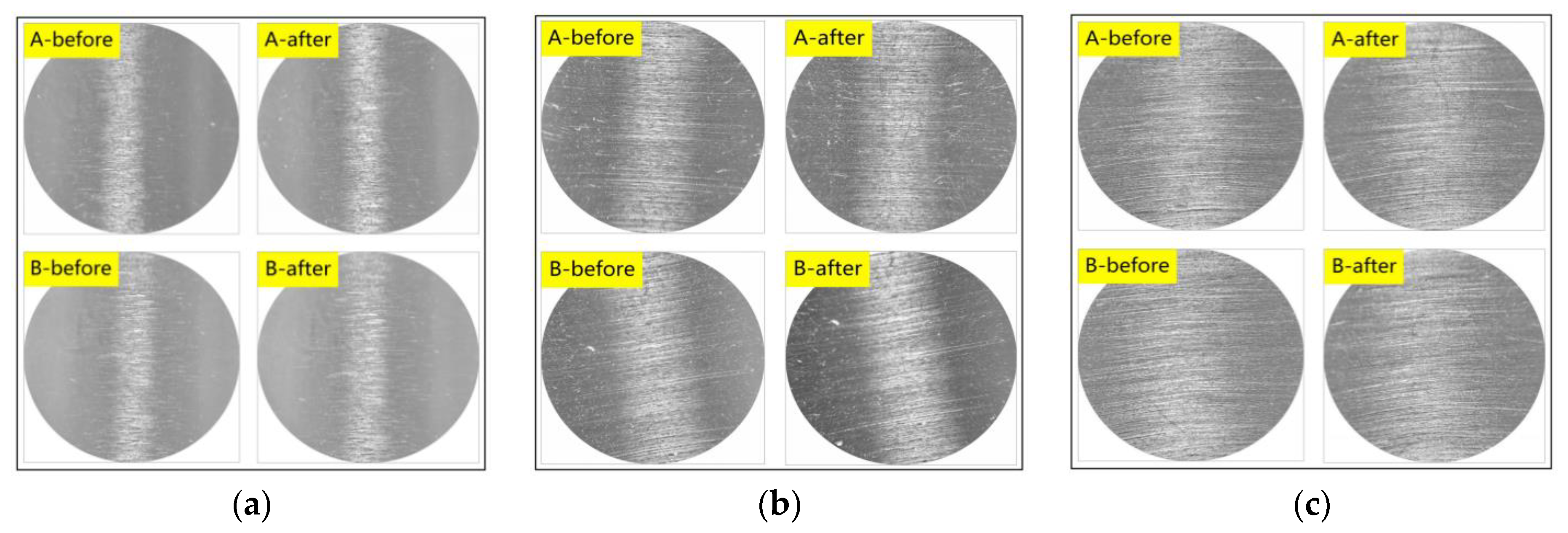
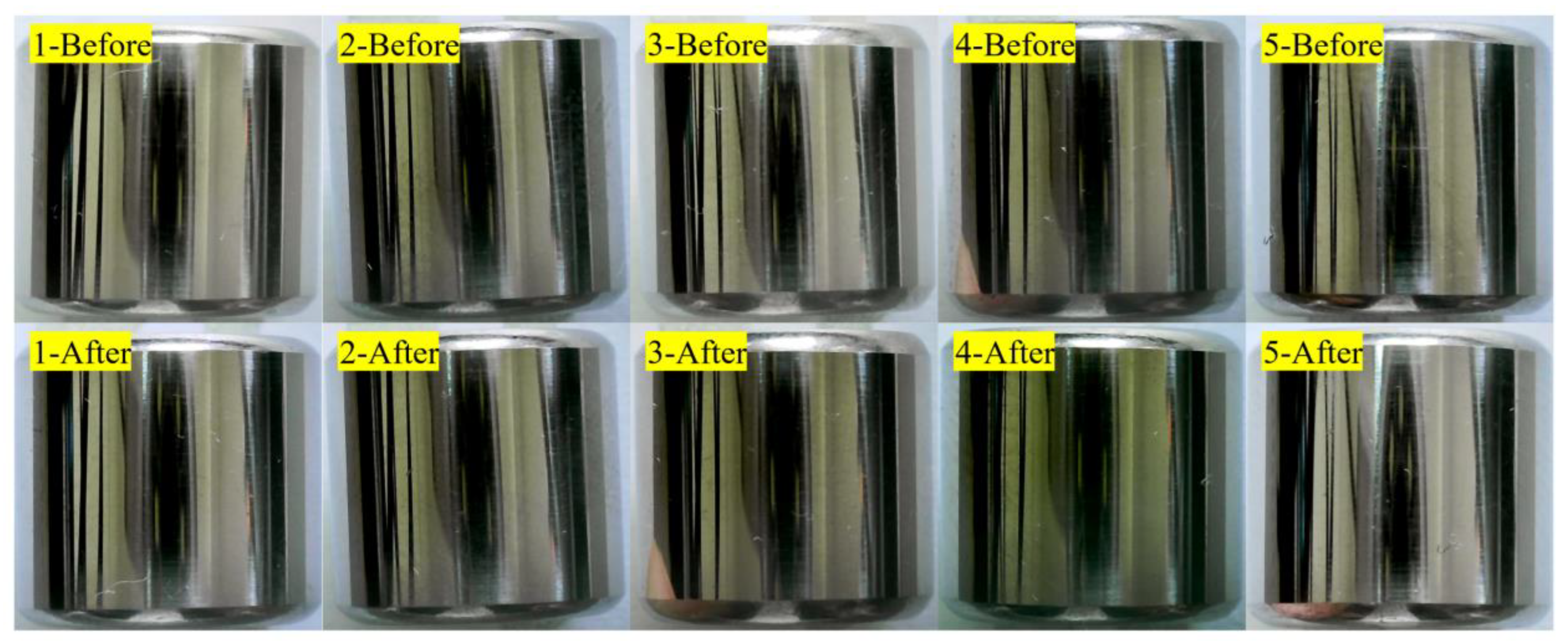
Test Results: The driving process of the cylindrical roller proceeded smoothly and without any discernible noise or disruptions. As illustrated in
Figure 12, the surface condition of the cylindrical roller following the drive remained indistinguishable from its pre-drive state. Furthermore, the actual speeds of the cylindrical roller, as outlined in
Table 2, closely corresponded to the predetermined speeds set for the air flotation electrical spindle. This congruence between actual and designated speeds underscores the precision and reliability of the drive mechanism.
To verify that the driving mechanism can meet the non-destructive detecting requirements for dynamic unbalance in precision cylindrical rollers, subsequent experiments were conducted to non-destructively detect dynamic unbalance in precision cylindrical rollers. The experimental results are as follows.
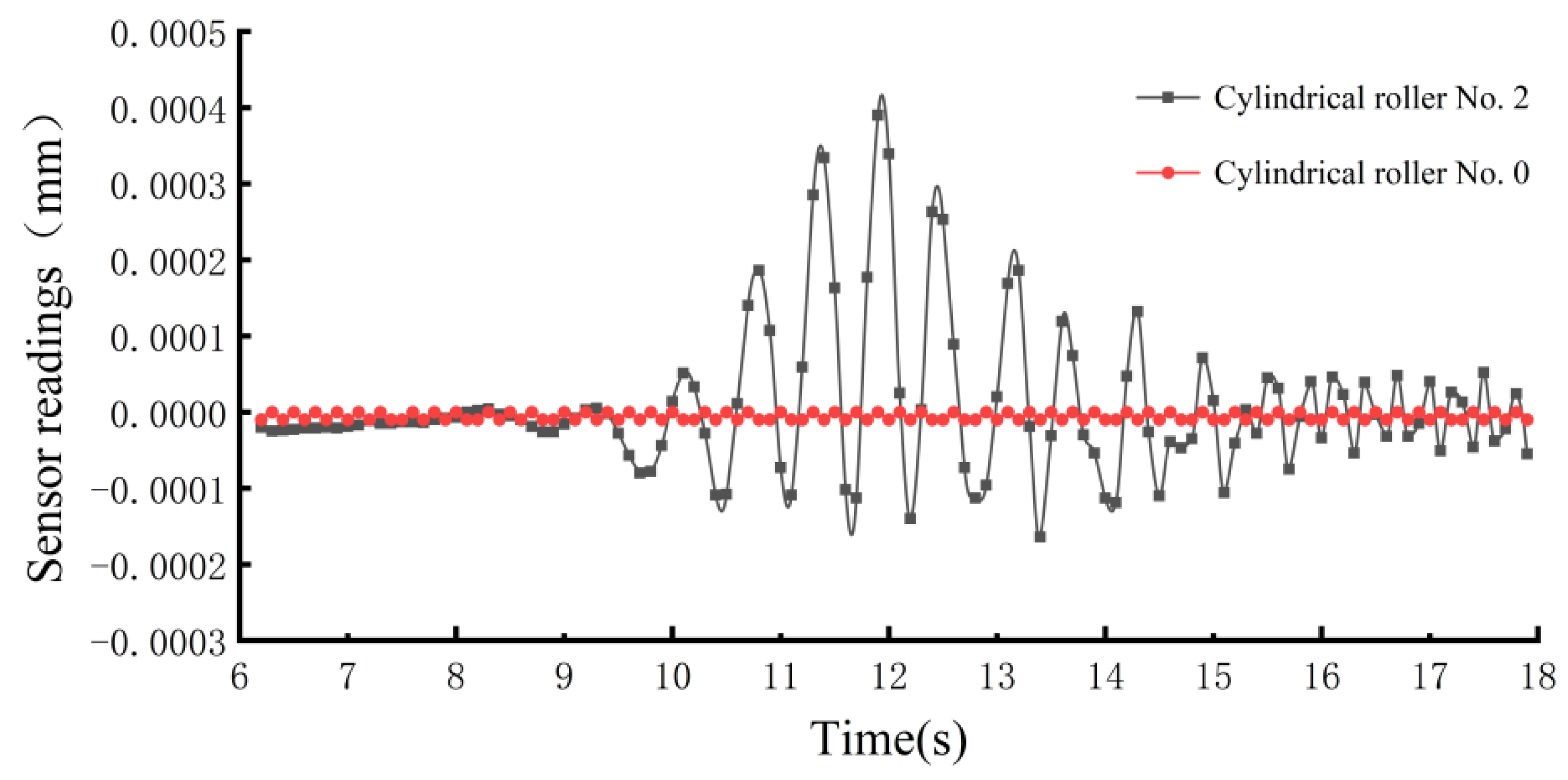
Figure 13 and
Figure 14 represent time–domain and frequency–domain signal plots, respectively. In
Figure 13, cylindrical roller No. 0 corresponds to a meticulously selected precision roller, which can be approximated as having negligible dynamic unbalance. Cylindrical roller No. 2, on the other hand, underwent manual de-weighting and exhibited a certain level of dynamic unbalance.
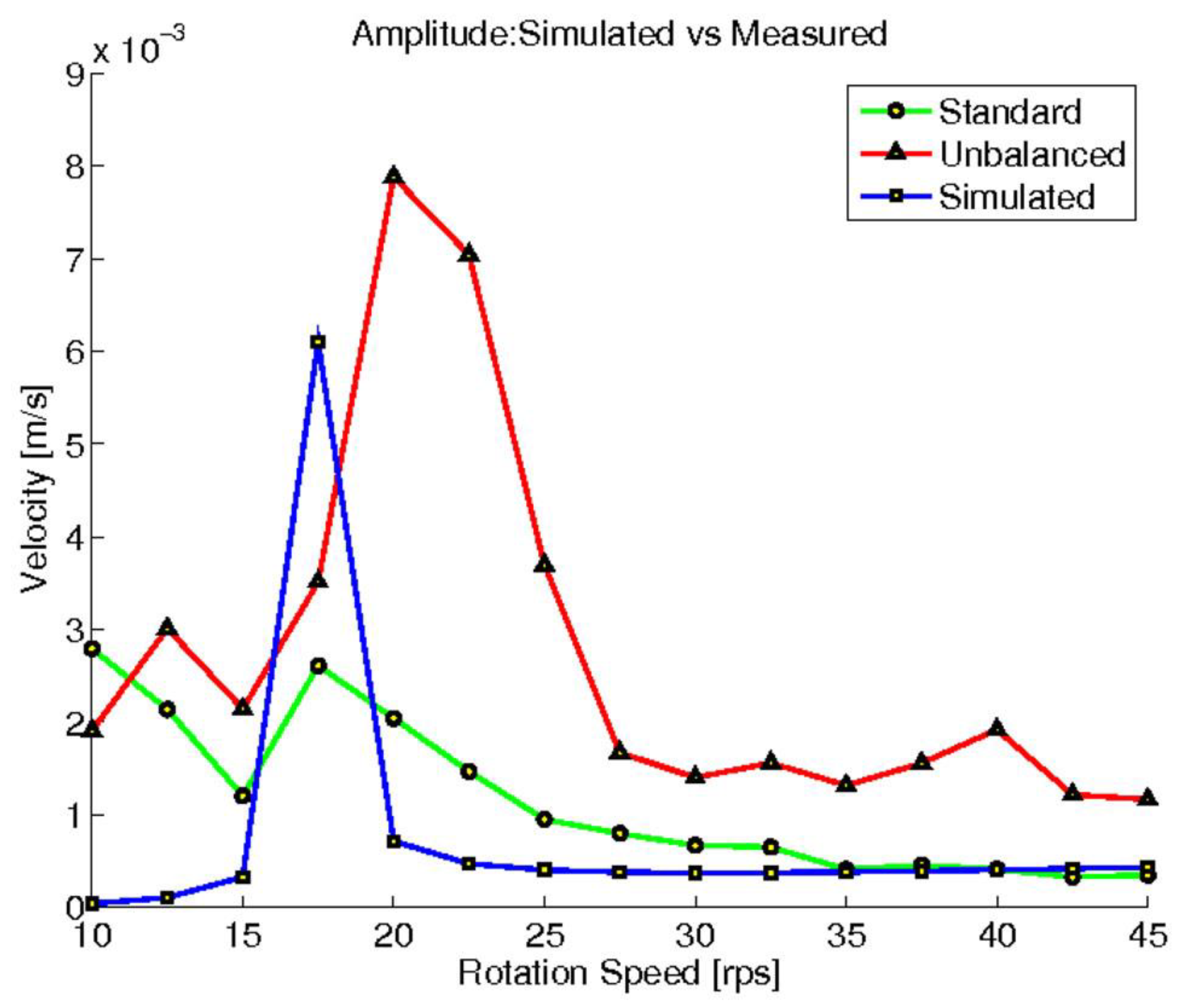
Figure 14 was sourced from reference [
9], depicting amplitude response curves for cylindrical rollers with dynamic unbalance (represented by the red line) and standard rollers (approximated as having negligible dynamic unbalance, represented by the green line).
Whether in the frequency–domain or time–domain signals, in the absence of external signal interference, theoretically, the excitation amplitude generated by a cylindrical roller with no dynamic unbalance should be zero. In
Figure 13, the cylindrical roller without dynamic unbalance exhibits a vibration signal close to zero, appearing nearly as a straight line. This observation suggests that the additional vibration signal interference introduced by the proposed driving mechanism in this study was minimal. In
Figure 14, even for cylindrical rollers without dynamic unbalance, there is a noticeable amplitude, largely attributed to interference from the driving mechanism.
Figure 15 displays surface images of cylindrical rollers involved in dynamic unbalance detection, captured using a color microscope.
7. Conclusions
The issue of dynamic unbalance in precision cylindrical rollers constitutes a crucial factor impacting the performance and lifespan of rolling bearings. Presently, commonly employed methods for detecting dynamic unbalance in the industry encounter challenges such as significant difficulty in implementation and susceptibility to surface damage during the driving process. These challenges substantially constrain the development of non-destructive detection techniques for dynamic unbalance. To address these issues, this study proposed a novel driving method. A mathematical model was established for the cylindrical roller and the bearing air film, with a parameterized simulation analysis conducted on the bearing air film. Theoretical analysis indicated that the driving mechanism can, in principle, rotate the cylindrical roller at high speeds without inducing relative sliding. Furthermore, it was established that the bearing air film can facilitate this motion.
To validate the feasibility of the proposed method, an experimental platform for the driving mechanism was constructed. Using this platform, cylindrical rollers of three different size specifications were individually accelerated to 12,000 RPM. Through a comparative analysis of the surface quality of the cylindrical rollers before and after driving, this study establishes that the proposed driving method can achieve the desired rotational speed for the cylindrical roller without causing surface damage. Subsequently, we conducted further experiments on dynamic unbalance detection, and the results indicate that the proposed driving method in this study can mitigate input vibration interference.
Future efforts will be devoted to optimizing and enhancing the structural design of the driving mechanism to reduce manufacturing costs and meet the non-destructive detection requirements for dynamic unbalance in diverse cylindrical rollers.


