Article

Lateral Dynamic Response of Helical Pile in Viscoelastic Foundation Considering Shear Deformation

1
School of Physics and Mechanical & Electrical Engineering, Hubei University of Education, Wuhan 430205, China
2
Engineering Research Centre of Rock–Soil Drilling & Excavation and Protection, Ministry of Education, Zhejiang Institute, China University of Geosciences, Wuhan 430074, China
3
China Railway 16th Bureau Group No. 3 Engineering Co., Ltd., Huzhou 313000, China
*
Author to whom correspondence should be addressed.
Appl. Sci. 2023, 13(22), 12220; https://doi.org/10.3390/app132212220
Submission received: 17 September 2023 / Revised: 2 November 2023 / Accepted: 3 November 2023 / Published: 10 November 2023

Abstract

:
Helical piles are a new type of pile that has good application prospects, and researchers have carried out an in-depth investigation into their vertical uplift and compressive bearing capacity. However, there is relatively little research on the dynamic bearing characteristics of helical piles. Therefore, the lateral vibration of a helical pile embedded in the viscoelastic foundation is systematically studied in this article. Utilizing the equivalent stiffness method to transform a helical pile into a cylindrical pile of special diameter, the lateral vibration model of the helical pile considering shear deformation is established based on the Winkler foundation model and the Timoshenko beam theory. The analytical solutions for the lateral dynamic displacement, bending moment, and shear force of the helical pile are strictly derived, and the rationality of the present solutions is also verified by comparing them with existing solutions. Based on the present solutions, a parametric study is carried out to investigate the influence of the pile and soil properties on the lateral dynamic response of the helical pile. It is found that the load excitation frequency and pile–soil stiffness ratio have a significant influence on the lateral dynamic displacement, bending moment, and shear force of the helical pile with space and time response.

1. Introduction

The helical pile is a new type of variable cross-section pile foundation, whose side surface is attached by helixes to enhance the interaction between the pile body and soil [1,2,3]. The existence of helixes can raise the lateral friction resistance of helical piles, leading to their increasingly widespread application in engineering, especially for some structures that mainly undergo lateral loads such as wave load, wind load, and seismic load [4,5,6]. Therefore, in recent years, many scholars have paid attention to investigating the static and dynamic characteristics of helical piles due to their bearing advantages [7,8,9,10,11,12,13,14,15,16,17,18].
At present, many scholars mainly utilize model tests, field tests, and theoretical research methods to investigate the vertical deformation mechanism of helical piles. In the field of the vertical uplift bearing characteristics of helical piles, Dong et al. [19] conducted in-depth research on the transfer mechanism of pull-out load among the helixes, pile body, and soil by considering the size effect of the helixes. Hu et al. [20] obtained the distribution law of soil pressure on the side of a helical pile with a helix at its bottom under the condition of uplift. Wang et al. [21] conducted a comprehensive comparison of the freeze-pull characteristics of helical piles and cylindrical piles in cold soil areas, confirming that helical piles can reduce the freeze-pull disease of foundations in cold regions. Hao et al. [22] studied the interaction between the helixes of the multi-helix helical pile and its influence on the vertical uplift bearing capacity of the helical pile. Wang et al. [23] studied the influence of pile formation effect on the vertical uplift bearing capacity of the single-helix helical pile, and obtained the corresponding calculation formula of vertical uplift bearing capacity. Filho and Tsuha [24] studied the uplift performance of the grouting helical pile in residual soil. Feng et al. [25] investigated the vertical uplift bearing capacity of the micro helical pile in different soil layers under different loading modes through on-site experiments. In terms of the vertical compressive bearing characteristics of the helical pile, Meng et al. [26] and Black et al. [27] successively carried out systematic model tests on the vertical compressive bearing characteristics of helical piles in sand and soft clay. Furthermore, Zhang et al. [28] carried out systemic model tests to study the influence of design parameters of the helical pile on its vertical compressive bearing capacity and obtained the reasonable combined design parameters of the helical pile. Through model tests, Hu et al. [29], Dong et al. [30,31], Akopyan et al. [32], and Wang et al. [33] successively investigated the calculation theory of the vertical compressive bearing characteristics of the helical pile under different loading conditions and different soil properties, and obtained a series of useful calculation formulas.
According to the above literature review, the research on the vertical deformation mechanism of the helical pile has been extensive and in-depth, but there are still relatively few existing research results on the lateral bearing characteristics of the helical pile. However, Hu et al. [34] found that the existence of helixes would improve the lateral bearing capacity of the helical pile through a series of model tests. Hussein and El Naggar [9] as well as Elsawy et al. [35] also confirmed that the presence of helixes could improve the seismic resistance of the helical pile through large-scale shaking table tests. Meanwhile, Zhang et al. [36] derived a calculation formula for the lateral vibration characteristic of the helical pile by the equivalent stiffness method, and once again demonstrated that the changes in the pile parameters of the helical pile have a significant influence on its lateral vibration characteristics. Therefore, the lateral bearing behavior of the helical pile is also worth further research, especially the dynamic problems of helical piles widely used in wind power foundations, transportation foundations, and other engineering projects [37,38,39,40,41]. However, most of the existing research on the dynamic response of the helical pile and the dynamic interaction theory between helical pile and soil is based on the Euler beam model, and the breadth and depth of research are still insufficient. Further research is urgently needed on the lateral dynamic response (LDR) of the helical pile considering the pile–soil interaction [42].
In order to investigate the lateral vibration characteristics of the helical pile more realistically, this paper takes the shear deformation effect of the helical pile into account, and develops an equivalent stiffness method to establish the dynamic governing equations of the helical pile embedded in a viscoelastic foundation based on the Winkler foundation theory and the Timoshenko beam theory. Then, the analytical solutions for the lateral dynamic displacement (LDD), bending moment (BM), and shear force (SF) of the helical pile are strictly derived, and the rationality of the analytical solutions is also verified by comparing it with existing solutions. Based on the obtained solutions, the influence of pile and soil parameters on the lateral vibration characteristics of the helical pile with space and time response is investigated in detail. The relevant results can be utilized to guide the dynamic design of helical piles under lateral loads, especially suitable for the helical piles in marine engineering and the design of dynamic foundations on helical piles.

2. Equivalent Model of Helical Pile

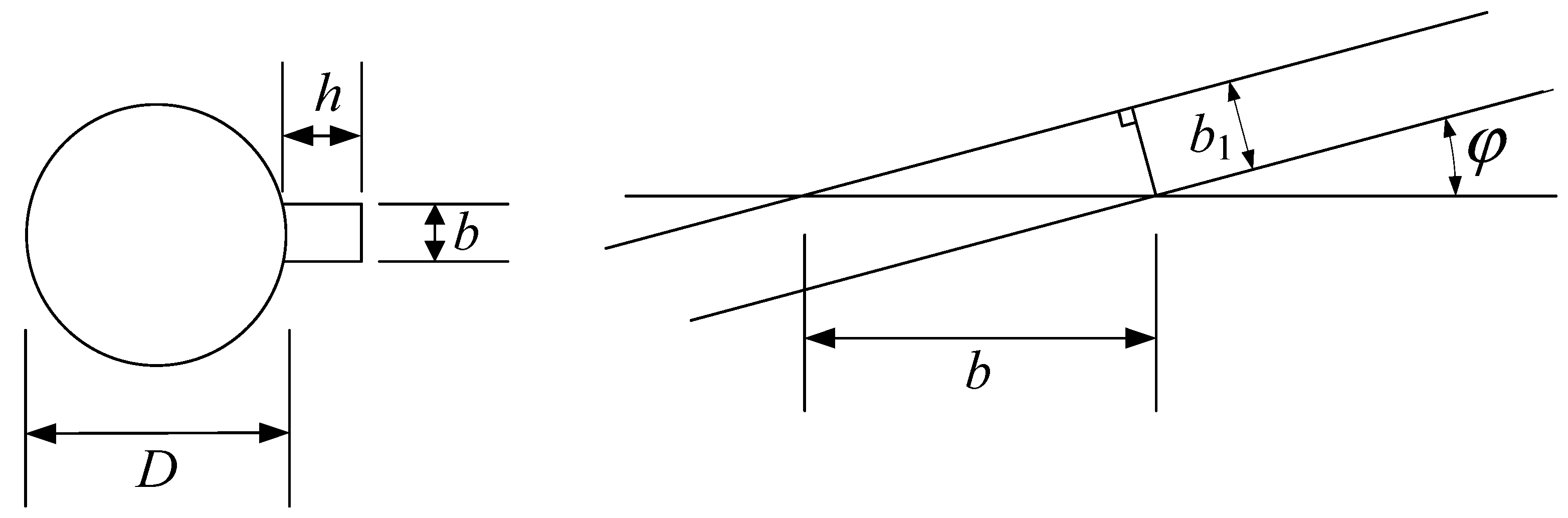
2.1. Establishment of Equivalent Model

Under the action of lateral exciting force at the pile top, bending stiffness is a key indicator determining the LDR of the helical pile [43,44,45]. Since the helical pile is a variable cross-section structure, it is necessary to establish a reasonable stiffness model for the helical pile body. As seen in Figure 1 D D 0 , and  H  are the diameter of the straight pile part, diameter of the helix part, and length of the helical pile, respectively. According to the equivalent stiffness method proposed by Zhang et al. [36], the helical pile can be equivalent to a cylindrical pile with the same stiffness, and the equation of equivalent stiffness can be written as
E p I p = E p I p ,
where  E p  and Ip denote the elastic modulus and cross-section inertia moment of the helical pile, respectively.  E p  and  I p  represent the elastic modulus and cross-section inertia moment of the equivalent cylindrical pile, respectively.
Since the helical pile and the equivalent cylindrical pile have the same composition materials, it can be obtained that  I p = I p  due to  E p = E p . Then, the equivalent diameter relationship between the helical pile and equivalent cylindrical pile can be found by comparing the two inertia moments. The inertia moment of the helical pile can be decomposed into two parts:
I p = I p 1 + I p 2 ,
where  I p 1 = π D 4 / 64  denotes the inertia moment of the straight pile part of the helical part, and  I p 2 = h b 3 / 12  represents the inertia moment of the helix part of the helical pile, respectively.
As shown in Figure 2, when the cutting helix is a lateral section, the vertical projection of its cross-section can be treated as a rectangle, where  h  is the length from the outer side of the helix part to the outer side of the straight pile part, i.e.,  h = ( D 0 D ) / 2 ; the width  b  is determined by the thickness  b 1  and the inclination angle of helixes  φ , i.e.,  b = b 1 csc φ . Then, the inertia moment of the helical pile can be rewritten as
I p = [ 3 π D 4 + 8 b 3 csc 3 φ ( D 0 D ) ] / 192 ,
The cross-section inertia moment of the equivalent cylindrical pile can be expressed as
I p = π D d 4 / 64 ,
where  D d  is the diameter of the equivalent cylindrical pile.

2.2. Validation of Equivalent Model

To prove the rationality of the equivalent stiffness conversion method in this article, the inertia moment of the helical pile given in Equation (3) is compared with that of the steel pipe helical pile obtained by Zhang et al. [36], i.e.,  I p = [ 3 π ( D d ) 4 + 8 b 3 csc 3 φ ( D 0 D ) ] / 192 , where  d  denotes the inner diameter of the steel straight pipe part, and the meanings of the other parameters are the same as those shown in Figure 1. It can be noted that, when  d 0 , the inertia moment of the steel pipe helical pile obtained by Zhang et al. [36] can be degraded to the inertia moment given in Equation (3). This indicates that the equivalent stiffness conversion results of the two pile types are consistent, thus verifying the rationality of the present equivalent model.

3. Governing Equations and Their Solutions

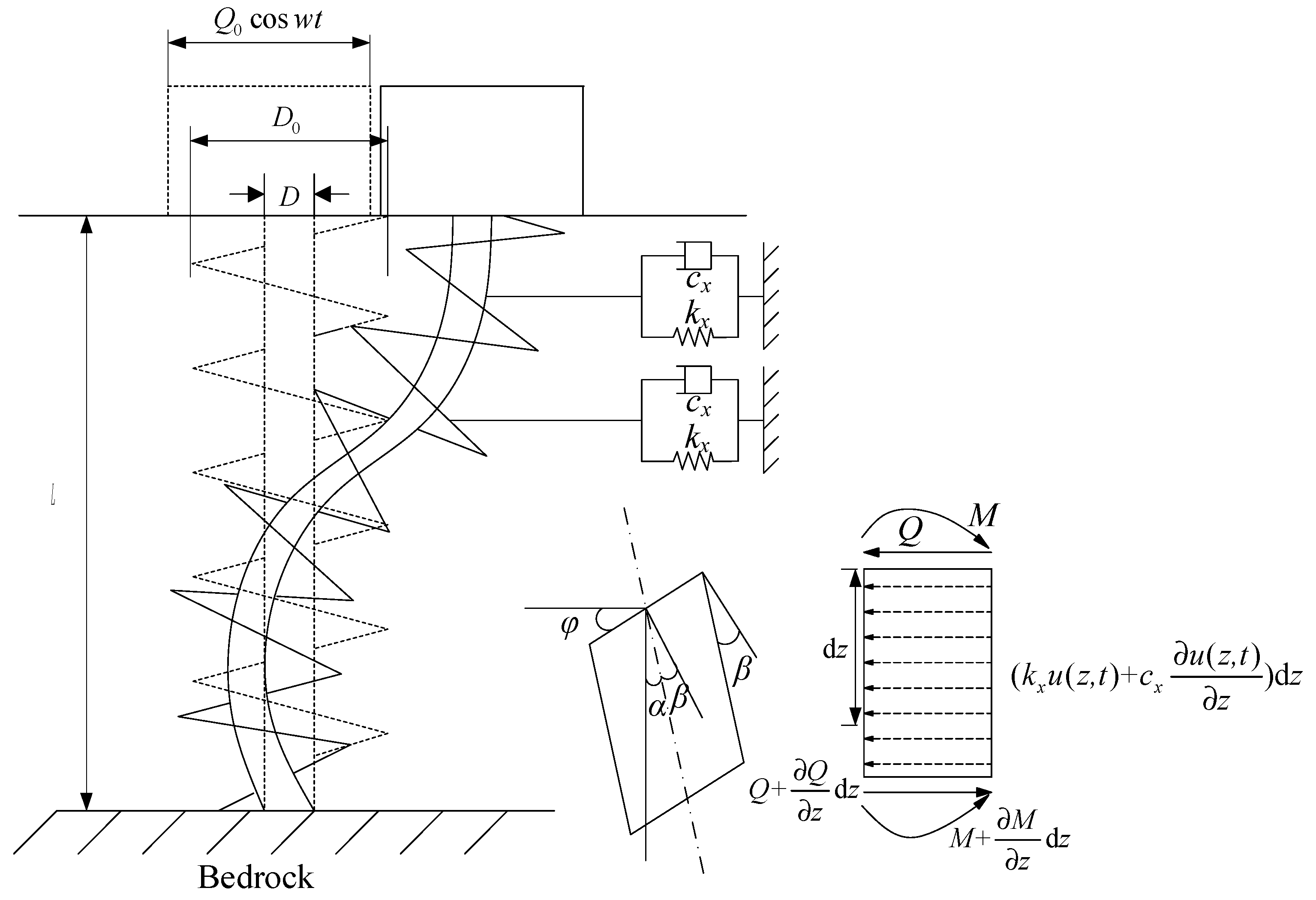
3.1. Dynamic Equation of Soil

Following the work of Gazetas and Dobry [46], the stiffness coefficient of the pile–surrounding soil can be obtained as
k x = 1.2 E s ,
The damping coefficient of pile–surrounding soil can be gained as
c x 6.0 a 0 1 4 ρ s V s D d + 2 k x β s ω ,
where  k x  and  c x  are the stiffness and damping coefficients of pile–surrounding soil, respectively;  V s = E s / 2 ρ s ( 1 + ν s )  represents the shear wave velocity of pile–surrounding soil;  β s ρ s E s , and  ν s  are the damping ratio, density, elastic modulus, and Poisson’s ratio of pile–surrounding soil;  ω  denotes the circular frequency, and  a 0 = ω D d / V s  represents the dimensionless frequency, respectively.

3.2. Dynamic Equation of Helical Pile

Timoshenko [47] modified the Euler beam theory and proposed a more accurate beam deformation theory which can consider the effects of shear deformation and rotational inertia on the lateral vibration characteristics of the pile. Furthermore, Wang [48] found that the influence of rotational inertia of the beam cross-section in Timoshenko’s equation on the beam vibration characteristic was so small that it would not be considered in this paper. Figure 3 shows the schematic of the pile–soil interaction model, in which  φ  represents the rotation angle of the pile cross-section,  α  denotes the inclination angle of the elastic axis, and  β  means the shear deformation angle, respectively.
To solve the governing equation more conveniently and ensure the universality of the results, this article proposes the following assumptions:
(1)
The pile’s surrounding soil is a homogeneous, isotropic, and viscoelastic medium. Therefore, the stiffness and damping coefficients of the soil layers are both constants along the vertical direction.
(2)
The pile body is a combination of circular and rectangular sections, and only the bending deformation of the pile is considered after simplification.
(3)
The pile–soil system is subjected to small deformations and strains during lateral vibration, and the longitudinal displacement of the pile’s surrounding soil is ignored.
(4)
No relative sliding occurs at the pile–soil interface.
(5)
The influence of pile cap is not considered.
(6)
The harmonic excitation acts horizontally on the pile top.
Utilizing the Timoshenko beam theory and combining it with the assumptions, the dynamic equilibrium equation of the helical pile can be derived as
{ k A p G p [ φ ( z , t ) z 2 u ( z , t ) z 2 ] + k x u ( z , t ) + c x u ( z , t ) t + m p 2 u ( z , t ) t 2 = 0 E p I p 2 φ j ( z , t ) z 2 + k A p G p [ u ( z , t ) z φ ( z , t ) ] = 0 ,
where  u ( z , t )  and  φ ( z , t )  denote the LDD and rotation angle of the cross-section of the pile element segment, respectively;  G p m p , and  A p  represent the shear modulus, pile element mass, and cross-section area of the helical pile, respectively;  k  denotes the shear coefficient of the cross-section, which is related to the shape of the cross-section. The meanings of the other symbols are consistent with the previous text.

3.3. Solutions of the Equations

For the steady-state lateral vibration of the pile–soil system, the dynamic equilibrium equation of the helical pile can be directly solved from the complex frequency domain, and the solutions of the equation can be written as
u ( z , t ) = U ( z ) e i ω t φ ( z , t ) = ψ ( z ) e i ω t ,
where  U ( z )  and  ψ ( z )  denote the amplitudes of the LDD and rotation angle of the helical pile, respectively.  i  denotes the imaginary unit.
For the convenience of solving, the following equations are set:
W p = E p I p , J p = k A p G p , k s = k x m p ω 2 + c x ω i ,
Substituting Equations (8) and (9) into Equation (7) yields
W p d 4 U ( z ) d z 4 k s W p J p d 2 U ( z ) d z 2 + k s U ( z ) = 0 ,
ψ ( z ) = W p J p d 3 U ( z ) d z 3 + ( 1 k s W p J p 2 ) d U ( z ) d z ,
The solution of Equation (10) can be derived as
U ( z ) = e α z ( A 1 cos β z + B 1 sin β z ) + e α z ( C 1 cos β z + D 1 sin β z ) ,
where  A 1 B 1 C 1 , and  D 1  are constants determined by the boundary conditions. The coefficients  α  and  β  satisfy the following equations:
α = k s 4 W p + k s 4 J p ,
β = k s 4 W p k s 4 J p ,
Substituting Equation (12) into Equation (11) gives
ψ ( z ) = e α z ( A 2 cos β z + B 2 sin β z ) + e α z ( C 2 cos β z + D 2 sin β z ) ,
According to the Material Mechanics, the BM and SF of the helical pile can be obtained as
M ( z ) = W p d ψ ( z ) d z = W p [ e α z ( A 3 cos β z + B 3 sin β z ) + e α z ( C 3 cos β z + D 3 sin β z ) ] ,
Q ( z ) = J p [ d U ( z ) d z ψ ( z ) ] = W p [ e α z ( A 4 cos β z + B 4 sin β z ) + e α z ( C 4 cos β z + D 4 sin β z ) ] ,
Combined with ,  B 1 C 1 , and  D 1 , the undetermined coefficients in Equations (15)–(17) can be obtained as
{ A 2 = A 1 t 5 + B 1 t 6 B 2 = A 1 t 6 + B 1 t 5 C 2 = C 1 t 5 + D 1 t 6 D 2 = C 1 t 6 D 1 t 5 ,
{ A 3 = A 1 t 7 + B 1 t 8 B 3 = A 1 t 8 + B 1 t 7 C 3 = C 1 t 7 D 1 t 8 D 3 = C 1 t 8 + D 1 t 7 ,
{ A 4 = A 1 t 9 + B 1 t 0 B 4 = A 1 t 0 + B 1 t 9 C 4 = C 1 t 9 + D 1 t 0 D 4 = C 1 t 0 D 1 t 9 ,
Since Equations (15)–(17) are derived from Equation (12), the undetermined coefficients satisfy certain equation relationships, which can be expressed as follows:
t 1 = e α z cos β z ,
t 2 = e α z sin β z ,
t 3 = e α z cos β z ,
t 4 = e α z sin β z ,
t 5 = α ( 1 k s W p J p 2 ) + W p J p ( α 3 3 α β 2 ) ,
t 6 = β ( 1 k s W p J p 2 ) + W p J p ( β 3 + 3 α 2 β ) ,
t 7 = α 2 β 2 k s J p ,
t 8 = 2 α β ,
t 9 = α k s J p α 3 + 3 α β 2 ,
t 0 = β k s J p + β 3 3 α 2 β ,
When the rotation angle of the pile top is constrained and the pile bottom is fixed, the boundary conditions can be obtained as
ψ ( z ) | z = 0 = 0 ; Q ( z ) | z = 0 = Q 0 U ( z ) | z = L = 0 ; ψ ( z ) | z = L = 0 ,
Utilizing Equations (21)–(30), the boundary conditions can be rewritten as
[ t 5 t 6 t 5 t 6 t 9 t 0 t 9 t 0 ] { X } = { 0 Q 0 / W p } ,
[ t 1 t 2 t 5 t 1 t 6 t 2 t 6 t 1 + t 5 t 2 t 3 t 4 t 5 t 3 t 6 t 4 t 6 t 3 t 5 t 4 ] { X } = { 0 0 } ,
Then, the solutions of undetermined coefficients  A 1 B 1 C 1 , and  D 1  can be obtained as
A 1 = Q 0 ˜ [ t 6 2 ( e 2 α L 1 ) + t 5 2 ( cos 2 β L 1 ) t 5 t 6 sin 2 β L ] / C ,
B 1 = Q 0 ˜ [ t 5 t 6 ( e 2 α L + cos 2 β L ) + t 5 2 sin 2 β L ] / C ,
C 1 = Q 0 ˜ [ t 6 2 e 2 α L + t 5 2 cos 2 β L + t 5 t 6 sin 2 β L t 5 2 t 6 2 ] / C ,
D 1 = Q 0 ˜ [ t 5 t 6 ( e 2 α L cos 2 β L ) + t 5 2 sin 2 β L ] / C ,
where
Q 0 ˜ = Q 0 E p I p ( t 5 t 0 t 6 t 9 ) ,
C = t 6 ( e 2 α L e 2 α L ) + t 5 ( 2 sin 2 β L ) .

4. Verification of the Present Solutions

The values of pile and soil parameters related to helical pile refer to the parameters provided by Hu et al. [49]. Unless otherwise specified, the values are shown in Table 1.
The maximum values of deformation and internal force are important parts to be considered in engineering design. Therefore, the variation law of the maximum values of the LDD, BM, and SF of the helical pile are studied in this paper. For the convenience of analysis, the following dimensionless parameters are introduced:
U max ( z ) = E p D u max / ( 500 Q 0 ) ,
M max ( z ) = m max / ( 2 Q 0 D ) ,
Q max ( z ) = q max / Q 0 ,
where  u max m max , and  q max  denote the maximum values of the LDD, BM, and SF of the helical pile, respectively;  U max M max , and  Q max  denote the dimensionless maximum values of the LDD, BM, and SF of the helical pile, respectively.

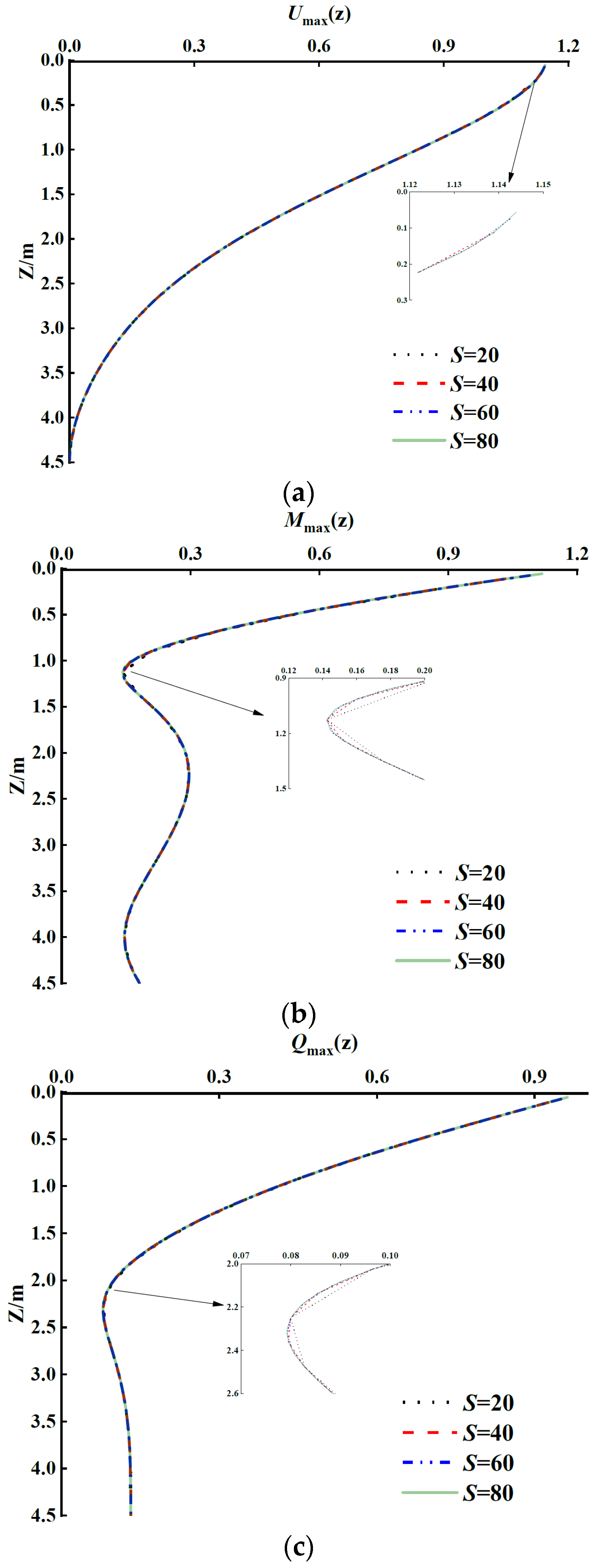
4.1. Element Division Accuracy of Pile–Soil System

The helical pile is divided into S units with equal thickness for the analysis of LDR. Therefore, the influence of element division accuracy of the pile–soil system on the LDR of the helical pile is firstly investigated. The number of the pile–soil system division elements is given as 20, 40, 60, and 80, respectively. The other parameters of the pile–soil system are set according to the parameters in Table 1. As shown in Figure 4, when the number of division elements approaches 80, the LDR curves of displacement, BM, and SF of the helical pile tend to be stable. In other words, if the number of pile–soil system division elements is high enough, i.e., S = 80 in this study, the calculation results can tend to be convergent. Therefore, unless otherwise specified, the number of pile–soil system division elements is given as S = 80 in the following sections.

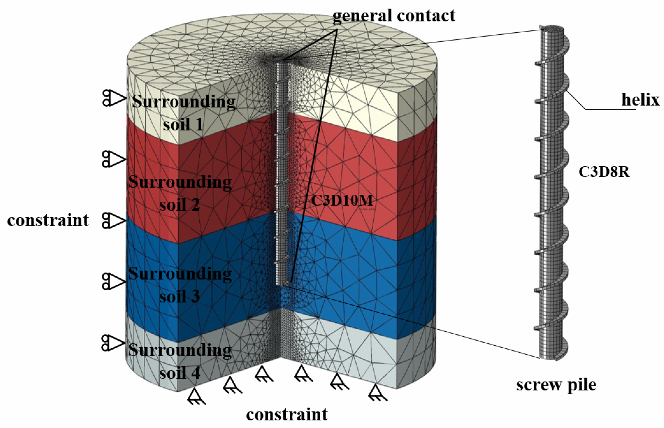
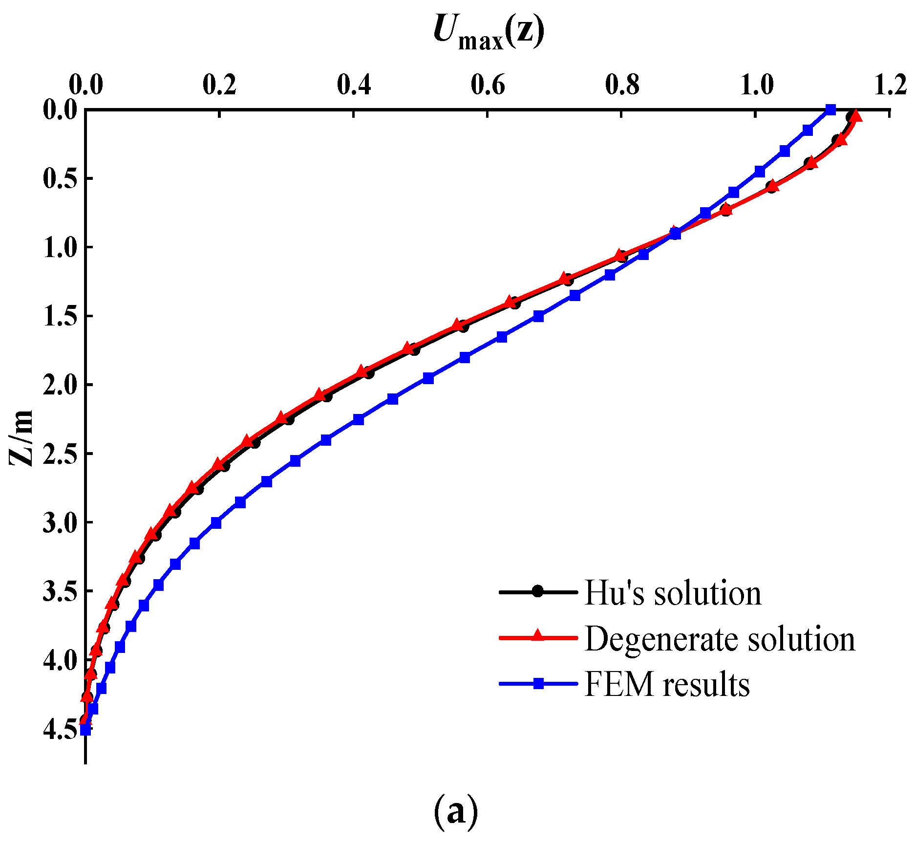
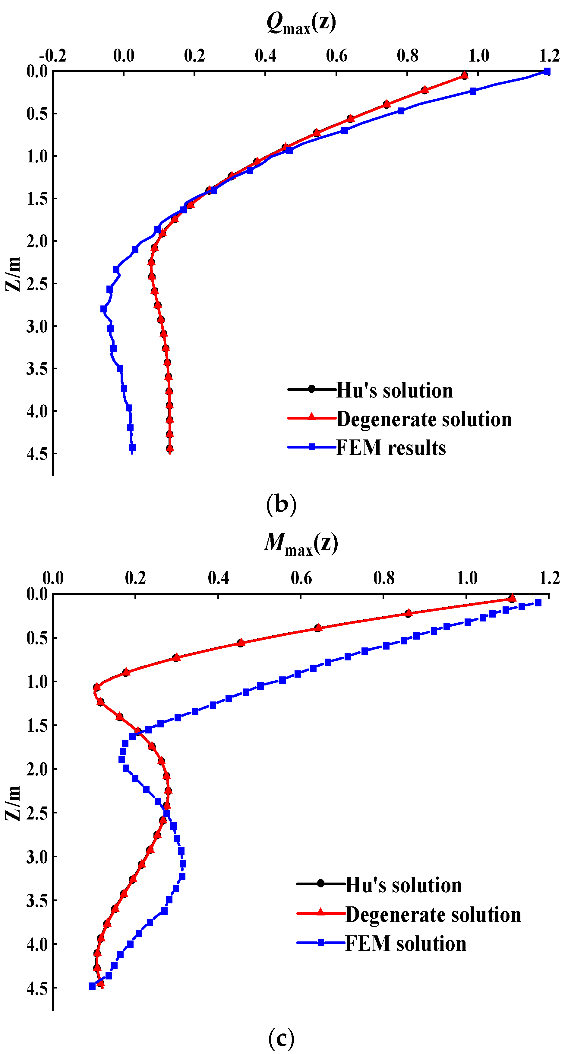
4.2. Comparison with Existing Analytical and FEM Solutions

To justify the correctness and rationality of the present solutions, the results computed from the present solution are successively compared with those computed from the analytical solution proposed by Hu et al. [49] and the FEM results obtained from the Abaqus. The mesh of the FE model is presented in Figure 5, and the total number of the meshes is 510,677. A four-layered soil case is investigated in this section. The interactions between the soil and pile are modelled as general contact, in which no slippage is allowed during the analysis. To compare the three kinds of solutions, the helical extension ratio  D 0 / D  is set as 1, and the other parameters of the pile–soil system are shown in Table 1. Figure 6 illustrates the LDR, BM, and SF of the helical pile calculated by the three kinds of approaches. It is found that the calculation results are in perfect consistency with Hu’s solution, whereas some acceptable differences are observed between the analytical and FEM results. It cannot be denied that the FEM solution has significant advantages of finely simulating the helix–soil interaction over the analytical solutions. However, due to the complex geometry of the screw pile, the mesh and convergence of the FE model could consume a significant amount of time. In this case, the FEM model takes 4 h and 23 min to finish, the calibration of the computer includes an Intel i9-13900K processor (Intel, Santa Clara, CA, USA), 32 GB RAM, a Nvidia GeForce RTX 4080 (NVIDIA, Santa Clara, CA, USA), whereas the proposed analytical solution only takes a few seconds to complete.
To further prove the present solutions, they are also compared with the lateral vibration solutions of the helical pile proposed by Wang et al. [50], in which the helical pile is simulated by Euler beam theory. Next, the difference between the calculated results by the present solutions and the solutions of Wang et al. [50] is investigated under different inclination angles of the helix, which is set at 5°, 30°, and 45°. The other parameters of the pile–soil system are shown in Table 1. Figure 7 depicts the LDR of displacement, BM, and SF of the helical pile obtained by the two kinds of solutions. It is found that the curve trends calculated by the two kinds of solutions are basically consistent. The LDD of the pile top increases with the increases in the helix inclination angle, and the BM of the pile end and the SF of the pile middle part increase with the decrease in the helix inclination. It is also found that, the smaller the helix inclination angle, the greater the degree of the above changes. Overall, the results calculated by the two kinds of solutions have a consistent trend, but there are still some differences in the variation trends of the BM of the pile bottom and the SF of the pile middle part, for the present solutions take the influence of shear deformation of the helical pile into consideration.

5. Parametric Study

In this section, the influences of pile and soil properties on the lateral vibration characteristics of the helical pile with space and time response are systemically investigated. Unless otherwise specified, the parameters in this section are the same as those in Section 4.

5.1. Space Response Analysis of Helical Pile

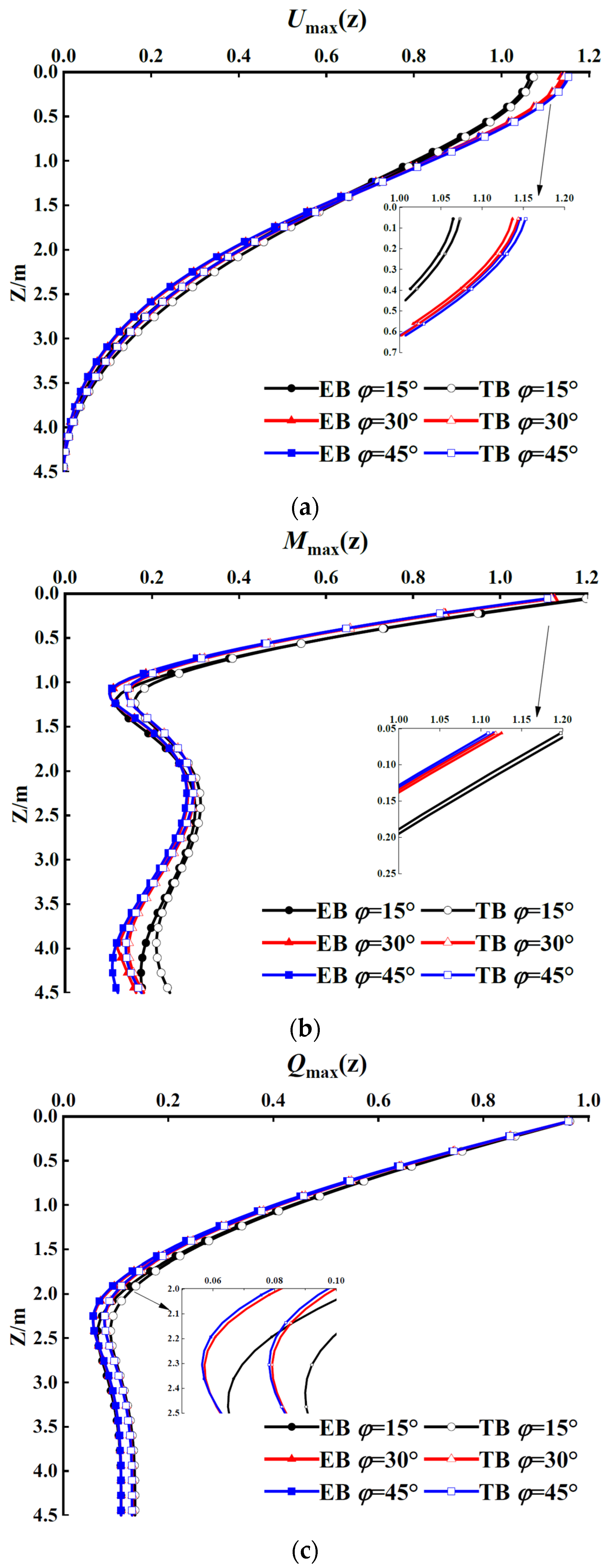
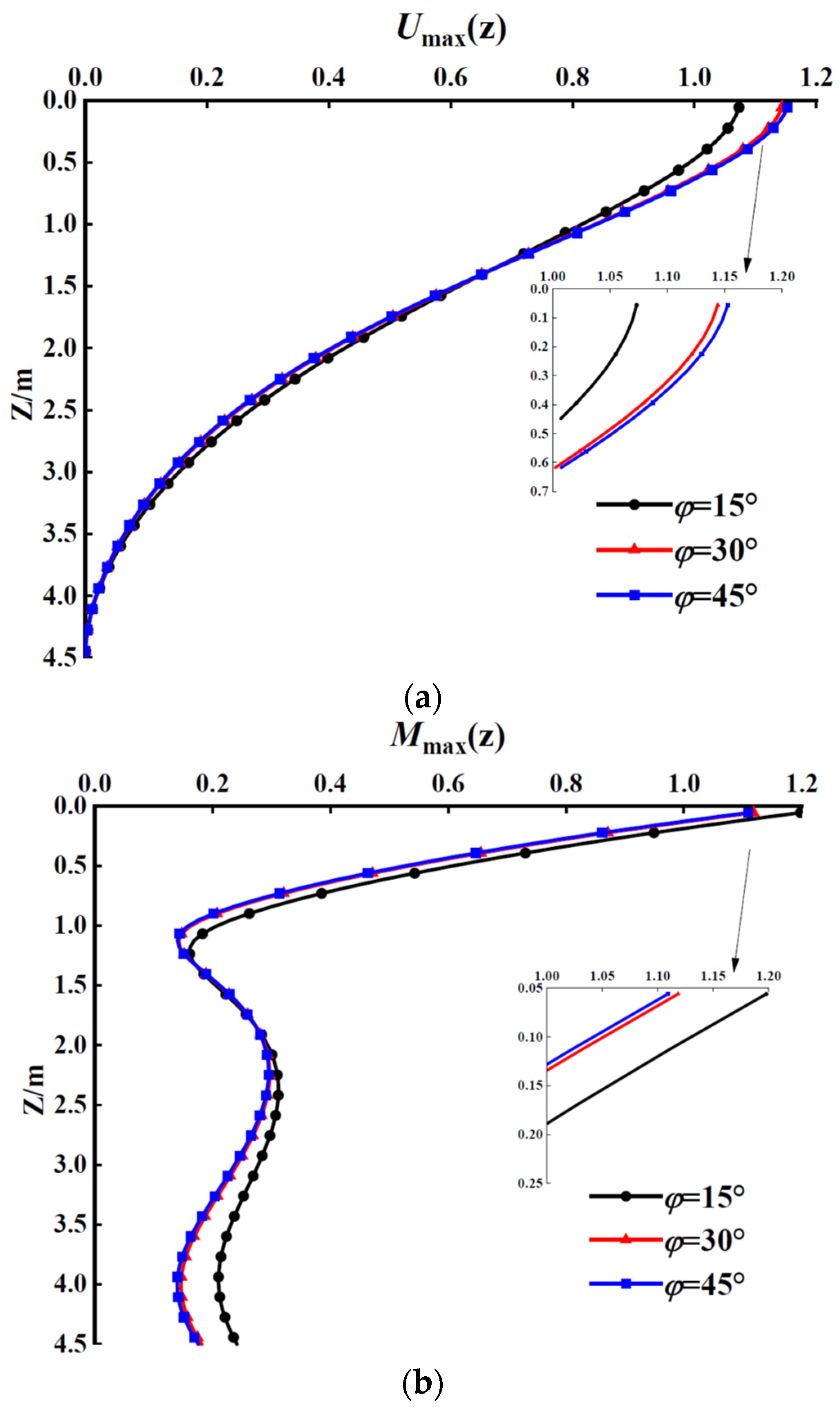
5.1.1. Influence of Helix Inclination Angle

According to the common design parameters of the helical piles, the helix inclination angle is set as 15°, 30°, and 45°, respectively. Figure 8 shows the influence of the helix’s inclination angle on the LDD, BM, and SF of the helical pile with space response. It can be found that the LDD of the pile top increases as the helix inclination angle increases. The BM of the pile end and the SF of the pile middle part increase as the helix inclination angle decreases. The reason for these phenomena may be that the decrease in the helix’s inclination angle increases the equivalent diameter and thus increases the stiffness of the helical pile. It is also found that, the smaller the helix’s inclination angle, the greater the degree of the above changes.

5.1.2. Influence of Dimensionless Frequency

The dimensional frequency is set as 0.1, 0.5, and 1, respectively, and the helix’s inclination angle is 30°. Figure 8 illustrates the influence of dimensionless frequency on the LDD, BM, and SF of the helical pile with space response. As shown in Figure 9a, the LDD of the helical pile decreases with the increase in the dimensionless frequency. The reason for this phenomenon is that, when the dimensionless frequency is too high, the load already generates a reverse force before the pile cross-section has significant deformation, for the response of the pile is not sensitive enough. As shown in Figure 9b, the BM of the helical pile decreases with increasing dimensionless frequency at the upper and lower parts of the pile, while it increases with increasing dimensionless frequency at the middle part of the pile. As shown in Figure 9c, at the upper part of the pile, the SF of the helical pile decreases with increasing dimensionless frequency, while at the lower part of the pile, the SF of the helical pile increases with increasing dimensionless frequency.

5.1.3. Influence of Pile–Soil Stiffness Ratio

Keeping  E s  unchanged,  E p / E s  is set as 1000, 5000, and 10,000, and the other parameters are shown in Table. Figure 10 depicts the influence of the pile–soil stiffness ratio on the LDD, BM, and SF of the helical pile with space response. Overall, all the LDD, BM, and SF of the helical pile visibly increase as the pile–soil stiffness ratio increases. The reason for this phenomenon is that, when the pile–soil stiffness becomes large, the ability of the soil to resist deformation decreases compared to the increasing pile stiffness. Therefore, in the lateral dynamic design of the helical pile, it is necessary to set a reasonable pile–soil stiffness ratio, rather than blindly increasing the pile’s body stiffness.

5.2. Time response Analysis of Helical Pile

In order to further investigate the time response of the helical pile, three representative positions are selected at the pile top, middle part, and pile end of the helical pile, that is, z = 0 m, 2 m, and 4.5 m, respectively. The range of analysis time is greater than one cycle. Here, taking the influence of dimensionless frequency on the helical pile as an example, the time response of the LDD, BM, and SF at different positions of the helical pile is studied, and the following dimensionless parameters are introduced:
U ( t ) = E p D u / ( 500 Q 0 ) ,
M ( t ) = m / ( 2 Q 0 D ) ,
Q ( t ) = q / Q 0

5.2.1. Analysis of Displacement Time Response

The dimensionless frequency is set as 0.1, 0.5, and 1, respectively, and the other parameters are shown in Table 1. Figure 11 illustrates the influence of dimensionless frequency on the displacement time response of the pile top, middle part, and pile end of the helical pile. It is found that, the larger the dimensionless frequency, the less time it makes for the LDD to reach its maximum value, for an increase in the dimensionless frequency is essentially an increase in the vibration frequency. The LDD of the pile end is significantly reduced to the small point where it can be ignored, for the pile end is fixed. It is also found that, the smaller the dimensionless frequency, the greater the change degree in displacement time response, for the change in dimensionless frequency leads to nonlinear change in damping coefficient and period. In summary, the dimensionless frequency has a significant impact on the displacement time response of the helical pile, and the smaller the dimensionless frequency, the greater the impact. Therefore, in the lateral dynamic design of the helical pile, the correlation between the natural frequency of the helical pile–soil system and the load frequency should be considered carefully to avoid the generation of resonance frequency.

5.2.2. Analysis of Bending Moment Time Response

Figure 12 illustrates the influence of dimensionless frequency on the BM time response of the pile top, middle part, and pile end of the helical pile. It is found that, the higher the dimensionless frequency, the smaller the time required for the BM to reach its maximum value. The dimensionless frequency has little influence on the maximum value of the BM of the pile top and middle part of the helical pile, but the maximum value of BM at the pile end increases with the increase in the dimensionless frequency. Overall, the influence of different dimensionless frequencies on the BM at each position is significant, and the smaller the dimensionless frequency, the greater the influence.

5.2.3. Analysis of Shear Force Time Response

Figure 13 depicts the influence of dimensionless frequency on the SF time response of the pile top, middle part, and pile end of the helical pile. It is found that, the higher the dimensionless frequency, the less time it requires for the SF to reach its maximum value. Except for periodic changes, different dimensionless frequencies have little effect on the maximum values of SF at the top and middle part of the helical pile. However, at the end of the helical pile, different dimensionless frequencies have a more significant influence on the maximum SF of the helical pile, and the smaller the dimensionless frequency, the greater the influence.

6. Conclusions

To promote the application of the helical pile in engineering mainly subjected to various lateral loads, based on the Winkler foundation model and the Timoshenko beam theory, this paper establishes the analytical solutions for the LDD, BM, and SF of the helical pile. Based on the present solutions, a parametric study is conducted to study the pile and soil properties on the LDR of the helical pile. The main conclusions are drawn as follows:
(1)
The LDD of the pile top increases with the increase in the helix inclination angle, but the BM of the pile top and pile end, as well as the SF of the middle part of the helical pile, increase with the decrease in the helix’s inclination angle. The smaller the helix’s inclination angle, the greater the change degree.
(2)
The LDD of the pile top decreases with the increase in the dimensionless frequency, while the SF of the pile end increases with the increase in the dimensionless frequency.
(3)
The LDR of the pile body basically increases significantly with the increase in the pile–soil stiffness ratio.
(4)
The smaller the dimensionless frequency, the more time it takes for the LDR to reach its maximum values, and the smaller the dimensionless frequency, the greater the change degree. The reason for these phenomena is that the change in dimensionless frequency results in nonlinear change in the damping coefficient and period.

Author Contributions

Conceptualization: X.Y., C.W. and W.W.; methodology: X.Y., S.C., F.W. and W.W.; software, X.Y., F.W. and W.W.; validation: X.Y., C.W. and F.W.; formal analysis: X.Y., S.C. and W.W.; investigation: X.Y., C.W., F.W. and W.W.; resources: S.C., F.W. and W.W.; data curation: X.Y., C.W. and W.W.; writing—original draft preparation: X.Y., C.W. and S.C.; writing—review and editing: F.W. and W.W.; visualization: X.Y. and S.C.; supervision: W.W.; project administration: W.W.; funding acquisition: F.W. and W.W. All authors have read and agreed to the published version of the manuscript.

Funding

This research was funded by the Research Project of Engineering Research Centre of Rock-Soil Drilling and Excavation and Protection, Ministry of Education (Grant No. 202305), the Natural Science Foundation of Hubei Province of China (2021CFB219), the National Natural Science Foundation of China (Grant Nos. 52178371, 52108355, 52208376), the Outstanding Youth Project of Natural Science Foundation of Zhejiang Province (Grant No. LR21E080005), the China Postdoctoral Science Foundation Funded Project (Grant No. 2022M712964), the Zhejiang Province’s 2022 Key R&D Plan Project-’Lingyan’ Project (2022C03151), the Science and Technology Project of Zhejiang Provincial Communication Department (202305-2), and the Construction Research Founds of Department of Housing and Urban–Rural Development of Zhejiang Province (Grant No. 2021K256).

Institutional Review Board Statement

Not appliable.

Informed Consent Statement

Not appliable.

Data Availability Statement

Data are contained within the article.

Conflicts of Interest

Authors S.C., F.W. and W.W. was employed by the company China Railway 16th Bureau Group No. 3 Engineering Co., Ltd. The remaining authors declare that the research was conducted in the absence of any commercial or financial relationships that could be construed as a potential conflict of interest.

References

  1. El Naggar, M.H.; Youssef, M.A.; Ahmed, M. Monotonic and cyclic lateral behaviour of helical pile specialized connectors. Eng. Struct. 2007, 29, 2635–2640. [Google Scholar] [CrossRef]
  2. Livneh, B.; El Naggar, M.H. Axial testing and numerical modeling of square shaft helical piles under compressive and tensile loading. Can. Geotech. J. 2008, 45, 1142–1155. [Google Scholar] [CrossRef]
  3. Fahmy, A.; El Naggar, M.H. Axial performance of helical tapered piles in sand. Geotech. Geol. Eng. 2017, 35, 1549–1576. [Google Scholar] [CrossRef]
  4. Elkasabgy, M.; El Naggar, M.H. Dynamic response of vertically loaded helical and driven steel piles. Can. Geotech. J. 2013, 50, 521–535. [Google Scholar] [CrossRef]
  5. Byrne, B.W.; Houlsby, G.T. Helical piles: An innovative foundation design option for offshore wind turbines. Philos. Trans. R. Soc. A 2015, 37, 20140081. [Google Scholar] [CrossRef]
  6. Spagnoli, G. A review on the behavior of helical piles as a potential offshore foundation system. Mar. Georesour. Geotec. 2020, 38, 1013–1036. [Google Scholar]
  7. Venkatesan, V.; Mayakrishnan, M. Behavior of mono helical pile foundation in clays under combined uplift and lateral loading conditions. Appl. Sci. 2022, 12, 6827. [Google Scholar]
  8. Ren, G.F.; Wang, Y.X.; Tang, Y.Q.; Zhao, Q.X.; Qiu, Z.G.; Luo, W.H.; Ye, Z.L. Research on lateral bearing behavior of spliced helical piles with the SPH method. Appl. Sci. 2022, 12, 8215. [Google Scholar] [CrossRef]
  9. Hussein, A.F.; El Naggar, M.H. Dynamic performance of driven and helical piles in cohesive soil. Acta Geotech. 2023, 18, 1543–1568. [Google Scholar]
  10. Shao, K.; Su, Q.; Liu, K.W.; Shao, G.X.; Zhong, Z.B.; Li, Z.Q. A new modified approach to evaluating the installation power of large-diameter helical piles in sand validated by centrifuge and field data. Appl. Ocean Res. 2021, 114, 102756. [Google Scholar]
  11. Zhang, Y.P.; El Naggar, M.H.; Wu, W.B.; Wang, Z.Q.; Yang, X.Y.; Jiang, G.S. Dynamic torsional impedance of large-diameter pipe pile for offshore engineering: 3D analytical solution. Appl. Math. Model. 2022, 111, 664–680. [Google Scholar]
  12. Wu, W.B.; Lu, C.H.; Chen, L.B.; Mei, G.X.; El Naggar, M.H.; Liu, H. Horizontal vibration characteristics of pile groups in unsaturated soil considering coupled pile-pile interaction. Ocean. Eng. 2023, 281, 115000. [Google Scholar]
  13. Cui, C.Y.; Meng, K.; Xu, C.S.; Wang, B.L.; Xin, Y. Vertical vibration of a floating pile considering the incomplete bonding effect of the pile-soil interface. Comput. Geotech. 2022, 150, 104894. [Google Scholar] [CrossRef]
  14. Su, C.C.; Lu, D.C.; Zhou, X.; Wang, G.S.; Zhuang, X.Y.; Du, X.L. An implicit stress update algorithm for the plastic nonlocal damage model of concrete. Comput. Method. Appl. M. 2023, 414, 116189. [Google Scholar] [CrossRef]
  15. Cui, C.Y.; Liang, Z.M.; Xu, C.S.; Xin, Y.; Wang, B.L. Analytical solution for horizontal vibration of end-bearing single pile in radially heterogeneous saturated soil. Appl. Math. Model. 2023, 116, 65–83. [Google Scholar] [CrossRef]
  16. Al-Jeznawi, D.; Jais, I.B.M.; Albusoda, B.S.; Alzabeebee, S.; Al-Janabi, M.A.Q.; Keawsawasvong, S. Response of pipe piles embedded in sandy soils under seismic loads. Transp. Infrastruct. Geotechnol. 2023. [Google Scholar] [CrossRef]
  17. Orang, M.J.; Motamed, R.; Toth, J. Experimental evaluation of dynamic response of helical piles in dry sand using 1g shaking table tests. In Proceedings of the 7th International Conference on Earthquake Geotechnical Engineering, Rome, Italy, 17–20 June 2019; pp. 4226–4234. [Google Scholar]
  18. El Naggar, M.H. Recent advances in helical piles for dynamic and seismic applications. In Proceedings of the 4th International Conference on Performance Based Design in Earthquake Geotechnical Engineering, Beijing, China, 19 September 2022; pp. 24–49. [Google Scholar]
  19. Dong, T.W.; Liang, L.; Huang, L.Z.; Wang, M.S. Pullout test of screw pile foundation. Rock. Soil. Mech. 2009, 30, 186–190. (In Chinese) [Google Scholar]
  20. Hu, W.; Liu, K.S.; Zhang, Y.H.; Zou, G.H. Uplift loading test on full-scale single blade screw anchor pile. J. Civ. Archit. Environ. Eng. 2017, 39, 31–39. (In Chinese) [Google Scholar]
  21. Wang, T.F.; Liu, J.K.; Tai, B.W.; Lv, P. Model tests on frost jacking behaviors of helical steel piles. Chin. J. Geotech. Eng. 2018, 40, 1084–1092. (In Chinese) [Google Scholar]
  22. Hao, D.X.; Wang, D.; O’Loughlin, C.D.; Gaudin, C. Tensile monotonic capacity of helical anchors in sand: Interaction between helices. Can. Geotech. J. 2019, 56, 1534–1543. [Google Scholar] [CrossRef]
  23. Wang, L.; Zhang, Q.Y.; Ding, H.Y.; Tian, Y.H.; Qi, X. The uplift capacity of single-plate helical pile in shallow dense sand including the influence of installation. Mar. Struct. 2020, 71, 102697. [Google Scholar] [CrossRef]
  24. Filho, J.D.S.; Tsuha, H.C. Uplift performance of helical piles with cement injection in residual soils. Can. Geotech. J. 2020, 57, 1335–1355. [Google Scholar] [CrossRef]
  25. Feng, S.J.; Fu, W.D.; Chen, H.X.; Li, H.X.; Xie, Y.L.; Lv, S.F.; Li, J. Field tests of micro screw anchor piles under different loading conditions at three soil sites. Bull. Eng. Geol. Environ. 2021, 80, 127–144. [Google Scholar] [CrossRef]
  26. Meng, Z.; Chen, J.J.; Wang, J.H.; Yin, Z.Y. Study of model test on bearing capacity of screw piles in sand. Rock. Soil. Mech. 2012, 33, 141–145. [Google Scholar]
  27. Black, J.A.; Hird, C.C.; Stanier, S.A. Modelling helical screw piles in soft clay and design implications. Geotech. Eng. 2014, 167, 447–460. [Google Scholar]
  28. Zhang, X.C.; Han, C.Y.; Bai, Y.C.; Cao, Y.P. The experimental study on the bearing capacity of steel screw piles owing to the effects of geometrical structures of piles. Struct. Eng. 2019, 35, 178–183. (In Chinese) [Google Scholar]
  29. Hu, H.X.; Liu, J.; Zhu, S.P. Prediction of single ultimate bearing capacity of screwed casting pile. J. Cent. South Univ. 2007, 38, 1239–1244. (In Chinese) [Google Scholar]
  30. Dong, T.W.; Liang, L.; Wang, M.S.; Zhang, J.C. Pitch of screws and bearing capacity of screw piles under ultimate load. Chin. J. Geotech. Eng. 2006, 28, 2031–2034. (In Chinese) [Google Scholar]
  31. Dong, T.W.; Liang, L. Solution of load-settlement function of single screw pile under axial pressure. Chin. J. Geotech. Eng. 2007, 29, 1483–1487. (In Chinese) [Google Scholar]
  32. Akopyan, V.; Akopyan, A. Experimental and theoretical investigation of the interaction of the reinforced concrete screw piles with the surrounding soil. Procedia Eng. 2016, 150, 2202–2207. [Google Scholar] [CrossRef]
  33. Wang, J.; Qiu, C.; Cao, W.; Wu, M. Calculation method discussion on bearing capacity of screw pile in clay based on load test. Spec. Struct. 2017, 34, 65–70. (In Chinese) [Google Scholar]
  34. Hu, W.; Meng, J.W.; Liu, S.K.; Long, C.B.; Yao, C.; Gong, W.H. Experimental and theoretical researches on horizontal bearing mechanism of single screw anchor pile. Chin. J. Geotech. Eng. 2020, 42, 158–167. (In Chinese) [Google Scholar]
  35. Elsawy, M.K.; El Naggar, M.H.; Cerato, A.; Elgamal, A. Seismic performance of helical piles in dry sand from large-scale shaking table tests. Géotechnique 2019, 69, 1071–1085. [Google Scholar] [CrossRef]
  36. Zhang, X.C.; Bai, Y.C.; He, Z.Q.; Zhu, A. Research on the dynamical response characteristics of steel screw pile under lateral vibration. Chin. J. Constr. Mach. 2019, 17, 547–553. (In Chinese) [Google Scholar]
  37. Wu, W.B.; Zhang, Y.P. A review of pile foundations in viscoelastic medium: Dynamic analysis and wave propagation modeling. Energies 2022, 15, 9432. [Google Scholar] [CrossRef]
  38. Lin, Y.F.; Xiao, J.D.; Le, C.H.; Zhang, P.Y.; Chen, Q.S.; Ding, H.Y. Bearing characteristics of helical pile foundations for offshore wind turbines in sandy soil. J. Mar. Sci. Eng. 2022, 10, 889. [Google Scholar] [CrossRef]
  39. Kim, H.J.; Reyes, J.V.; Dinoy, P.R.; Park, T.W.; Kin, H.S.; Kim, J.Y. Modified p-y curves to characterize the lateral behavior of helical piles. Geomech. Eng. 2022, 31, 505–518. [Google Scholar]
  40. Chen, L.B.; Li, J.X.; Wu, W.B.; Liu, H.; Yao, Y.; Zhang, P. New method to calculate the kinematic response of offshore pipe piles under seismic S-waves. Soil. Dyn. Earthq. Eng. 2023, 165, 107651. [Google Scholar] [CrossRef]
  41. Liu, H.; Wu, W.B.; Yang, X.Y.; Liu, X.; Wang, L.X.; El Naggar, M.H.; Wen, M.J. Apparent wave velocity inverse analysis method and its application in dynamic pile testing. Int. J. Numer. Anal. Met. 2023, 47, 549–569. [Google Scholar] [CrossRef]
  42. Alnmr, A.; Ray, R.P.; Alsirawan, R. A state-of-the-art review and numerical study of reinforced expansive soil with granular anchor piles and helical piles. Sustainability 2023, 15, 2802. [Google Scholar] [CrossRef]
  43. Yu, J.; Shang, S.P.; Li, Z.; Ren, H.; Zeng, Y.L. Dynamical characteristics of an end bearing pile embedded in saturated soil under horizontal vibration. Chin. J. Geotech. Eng. 2009, 31, 101–108. (In Chinese) [Google Scholar]
  44. Liu, X.; Wang, L.X.; El Naggar, M.H.; Wu, W.B.; Liu, H.; Li, L.C.; Wang, K.H.; Mei, G.X.; Xiao, L. Dynamic analysis of layered soil-pile interaction based on the nearly continuous model. Ocean Eng. 2023, 279, 114457. [Google Scholar] [CrossRef]
  45. Lu, D.C.; Wu, C.Y.; Ma, C.; Du, X.L.; El Naggar, M.H. A novel segmental cored column for upgrading the seismic performance of underground frame structures. Soil. Dyn. Earthq. Eng. 2020, 131, 106011. [Google Scholar] [CrossRef]
  46. Gazetas, G.; Dobry, R. Horizontal response of piles in layered soils. Int. J. Geotech. Eng. 1984, 110, 20–40. [Google Scholar] [CrossRef]
  47. Timoshenko, P.S. On the correction for shear of the differential equation for transverse vibrations of prismatic bars. Philos. Mag. 1921, 41, 744–746. [Google Scholar] [CrossRef]
  48. Wang, G.Y. Vibration of Building Structures; Science Press: Beijing, China, 1978. [Google Scholar]
  49. Hu, A.F.; Xie, K.H.; Ying, H.W.; Qian, L. Analytic theory of horizontal vibration of single pile considering shear deformation of pile body in viscoelastic foundation. Chin. J. Rock. Mech. Eng. 2004, 23, 1515–1520. (In Chinese) [Google Scholar]
  50. Wang, C.Z.; Wu, J.; Wang, L.X.; Liu, H.; Wu, W.B. Horizontal vibration characteristics of screw pile in viscoelastic foundation. J. Cent. South Univ. 2022, 53, 2279–2289. (In Chinese) [Google Scholar]
Figure 1. Simplified schematic diagram of helical pile.
Applsci 13 12220 g001
Figure 2. Cross-section diagram of helix.
Applsci 13 12220 g002
Figure 3. Schematic of pile–soil interaction model.
Applsci 13 12220 g003
Figure 4. Influence of element division accuracy on LDR of helical pile. (a) Lateral displacement envelope. (b) BM envelope. (c) SF envelope.
Applsci 13 12220 g004
Figure 5. Mesh of FEM model established in Abaqus.
Applsci 13 12220 g005
Figure 6. Comparison between the present solutions and the solutions obtained by Hu et al. [49]. (a) Lateral displacement envelope. (b) BM envelope. (c) SF envelope.
Applsci 13 12220 g006aApplsci 13 12220 g006b
Figure 7. Comparison between the present solutions and the solutions obtained by Wang et al. [50]. (a) Lateral displacement envelope. (b) BM envelope. (c) SF envelope.
Applsci 13 12220 g007
Figure 8. Influence of helix inclination angle on LDR of helical pile. (a) Lateral displacement envelope. (b) BM envelope. (c) SF envelope.
Applsci 13 12220 g008aApplsci 13 12220 g008b
Figure 9. Influence of dimensionless frequency on LDR of helical pile. (a) Lateral displacement envelope. (b) BM envelope. (c) SF envelope.
Applsci 13 12220 g009aApplsci 13 12220 g009b
Figure 10. Influence of pile–soil stiffness ratio on LDR of helical pile. (a) Lateral displacement envelope. (b) BM envelope. (c) SF envelope.
Applsci 13 12220 g010
Figure 11. Analysis of displacement time response of helical pile. (a) Displacement time response at z = 0 m. (b) Displacement time response at z = 2 m. (c) Displacement time response at z = 4.5 m.
Applsci 13 12220 g011aApplsci 13 12220 g011b
Figure 12. Analysis of BM time response of helical pile. (a) BM time response at z = 0 m. (b) BM time response at z = 2 m. (c) BM time response at z = 4.5 m.
Applsci 13 12220 g012
Figure 13. Analysis of SF time response of helical pile. (a) SF time response at z = 0 m. (b) SF time response at z = 2 m. (c) SF time response at z = 4.5 m.
Applsci 13 12220 g013
Table 1. Parameters of pile and soil.
ParametersSymbolValueUnit
Pile diameterD0.3m
Pile lengthL4.5m
Helical extension ratioD0/D1.5-
Helical inclination angle   φ 30°
Helical tooth widthb0.075m
Dimensionless frequencya00.5-
Elastic modulus of pileEp2.0 × 1010Pa
Elastic modulus of soilEs4.0 × 106Pa
Pile density   ρ p 2.5 × 10³kg/m3
Soil density   ρ s 2.0 × 10³kg/m3
Pile’s Poisson’s ratio   ν p 0.17-
Soil’s Poisson’s ratio   ν s 0.4-
Soil’s damping ratio   β s 0.05-
External load amplitude   Q 0 100kN
Disclaimer/Publisher’s Note: The statements, opinions and data contained in all publications are solely those of the individual author(s) and contributor(s) and not of MDPI and/or the editor(s). MDPI and/or the editor(s) disclaim responsibility for any injury to people or property resulting from any ideas, methods, instructions or products referred to in the content.

