1. Introduction
The pace of global development of mankind requires the manufacture and use of an increasingly diverse range of materials with a role in supporting non-polluting industrial activity, with an increasingly accentuated reliability and durability in all fields of activity.
This reality makes advanced technology take on a new dimension. The manufacturing requirements formulated for the immediate perspective require the use of new concepts for the direct reuse of materials and supplies, thus avoiding raw material consumption and other resource management activities with significant costs. In the current context of industry development as well as the requirements imposed by the European Union through environmental legislation, the need to adapt manufacturing processes to reduce the negative impact on the environment leads to the research of new advanced procedures, transferable on an industrial scale to remove unjustified consumption up to the accepted limit of production standards. New geometries and design forms are developed with the help of additive manufacturing that gives strength and reduced weight to the components obtained using cheap and durable materials. The masked stereolithography apparatus (MSLA) provides improved sustainability in rapid prototyping and additive manufacturing using advanced, high-performance materials [
1,
2,
3] for a wide range of applications. Thus, the design of components through the polymerization of various resins and nanocomposite biomaterials, with the help of 3D printing, becomes a fast and precise process of forming products with good chemical and mechanical stability [
4,
5]. There are rapid prototyping processes that are known in the literature [
6,
7,
8]. Precision three-dimensional (3D) manufacturing technologies are used for advantageous freedom in designing and manufacturing complex applications specific geometries with little loss. MSLA printing methods are cost-effective, without defects and much faster, using intense ultraviolet (UV) light to cure successive layers of photosensitive resins. The MSLA technique has the advantage of having a high print resolution, giving a smooth surface finish and high object clarity.
This technique is used for biodegradable 3D printing, which has led to a reduced impact on the environment [
9,
10,
11]. Regardless of where it is used, the 3D scanning method has many benefits such as: it is fast (large field of view), it provides high precision data (even for irregular surfaces), it allows the creation of a very fine digital representation of the project (digital twin), and it can be processed, facilitating dimensional control in various industrial or reverse engineering applications. Therefore, the development of such technologies has brought multiple benefits in everyday life. The 3D laser scanners accurately capture tens of thousands of points per second and thus make it possible to accurately evaluate any scanned object. Three-dimensional scanning generates results that include areas, coordinates, sections, profiles, and volume calculations with maximum efficiency. The digitized three-dimensional file obtained after 3D scanning can reproduce the content of images captured using 3D printers. There are several 3D scanning methods based on distinct principles, each of these methods having its own advantages/disadvantages and, of course, different costs. The high precision of accurately measuring any space (including hard-to-reach ones) is reflected in increased productivity, with every angle, edge, or peak being calculated and rendered with minimal errors. The choice of the manufacturing method must take into account a series of quality indicators: accuracy (rigor), precision, sensitivity, selectivity, robustness, avoiding interference, and speed of determinations.
The combined technology of 3D scanning and MSLA printing thus becomes a necessity in the industrial environment as a result of the dynamic, highly detailed, and accurate rendering of existing dimensions and conditions, as well as the fineness and accuracy of the obtained object image [
12,
13]. The numerous needs it responds to leads to reduced costs, the elimination of laborious programming and documentation, simplifies the design process and accelerates the workflow, streamlines (virtual) communication, and mitigates the risk in the physical production of the object. These aspects respond to the circular economy concept by taking into account environmental sustainability, the potential for economic growth, and eco-industrial development.
By adopting the coupling of these techniques to design, scan, and print the volumetric flowmeter rotor, the authors are within the scope of the principles of reverse engineering by promoting innovation in technology. They also respond to the need to reduce and eliminate industrial waste and pollution by keeping materials in use, contributing to the regeneration of natural systems. Thinking about such a technology proves the understanding of practical implications of the circular economy, taking into account the needs and diversity of the market, but also the demands and diversity of sustainable uses of these products.
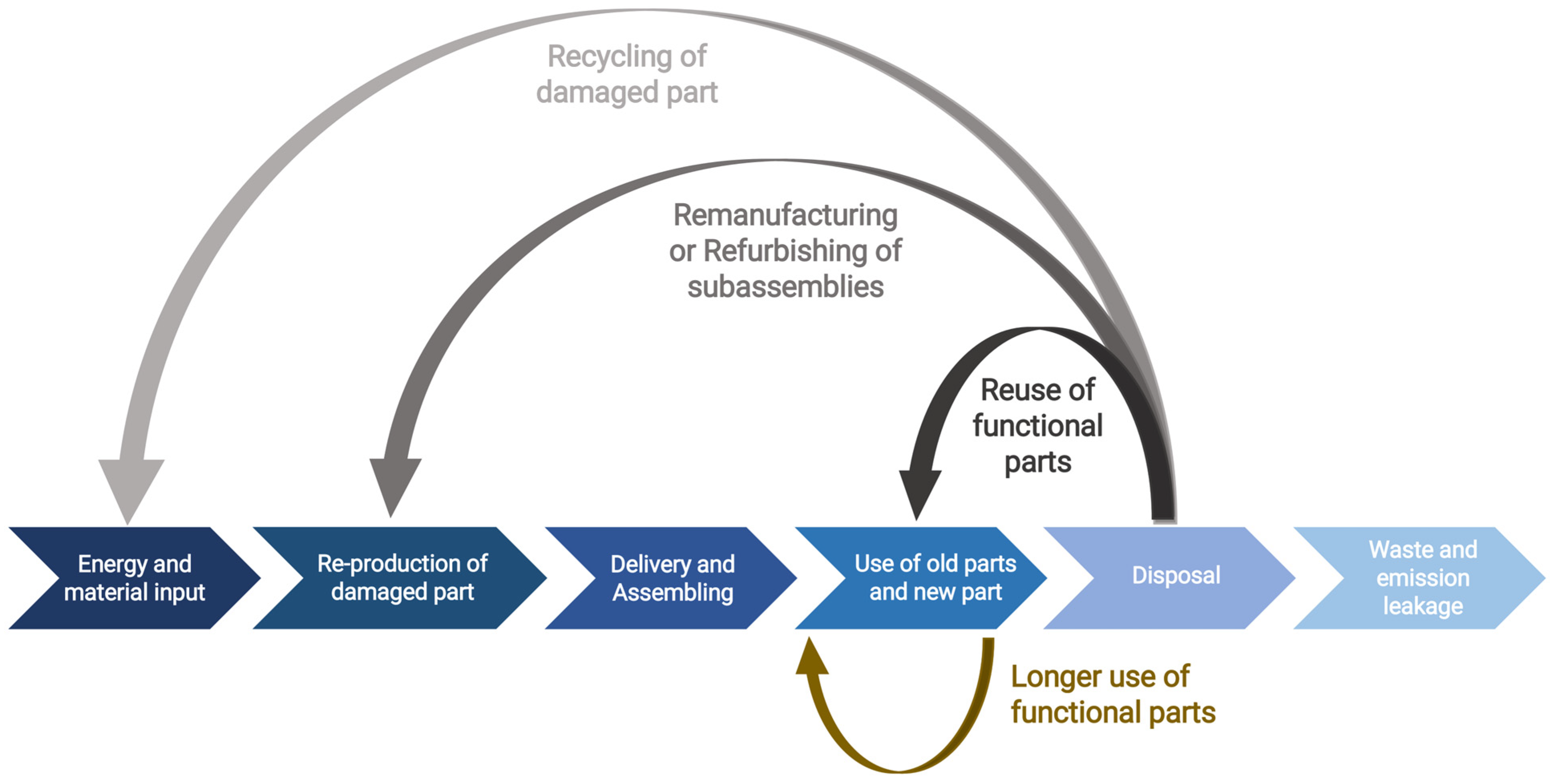
This method is part of the closed loop manufacturing process to reduce waste and industrial pollution. Another principle of the circular economy targeted by this eco-technology is that of extending the life of the remanufactured product, the life of the materials by keeping them in use as long as possible, and/or reusing the assembly. This principle, once achieved, also facilitates the third principle, namely the minimization of damage, alleviating the pressure on the environment. Designing products and processes through a good management of all stages of development and execution is an obvious benefit of the circular economy concept but also of the reverse engineering concept. Reverse engineering originates from the analysis of various devices and systems for commercial use [
14,
15]. The reverse engineering concept was approached long before modern technology could be used to copy technologies, devices, or information obtained through capture/espionage operations. This technology involves understanding the operation principles of a device, system, or software by analyzing its structure, function, and operations. The process is applied to increase production under conditions of high product competition, thus avoiding the effort encountered in the original design, with the aim being to make design decisions for the finished products with minimal or no additional knowledge of the procedures involved in the initial production. Reverse engineering is used to create three-dimensional virtual models of existing parts and subassemblies and is also useful for estimating costs and identifying potential patent infringements [
16,
17]. This desired technical competitive intelligence represents the understanding of the competition, the aspects related to competitive models that take place in the business environment, and the trend of the markets. Reverse engineering is a method of generating a virtual 3D model of a physical part to be used for computer-aided design (CAD), computer-aided manufacturing (CAM), computer-aided engineering (CAE), or other programs.
The process involves measuring an object then reconstructing it as a 3D model. To determine the dimensions of the physical object, 3D scanning technologies and equipment such as coordinate measuring machines (CMM), laser triangulation scanners, structured light scanners, and industrial computed tomography are also used [
18]. Reverse (reconstruction) engineering is useful to analyze the functionality of products and to analyze sub-components; it can be used to complete documents, specifically for parts designed before the development of CAD software. Measured data, usually represented as point clouds, do not contain topological information and so are often processed as a triangular mesh (STL) file, then modeled into a usable format, such as a set of non-uniform rational basis splines (NURBS) or a solid CAD model [
19,
20]. Small and large companies alike are using reverse engineering to bring physical geometry into the digital environment. It can be easily transferred to a computer screen, but the overall process is much more complex. Some companies use the reverse technique when they do not yet have similar products to create their own products. This information is also digital input data for processing in CAD software, which the computer uses for the integral design of the products, and the direct obtaining of the driving programs necessary for the manufacturing system, or CAM, which the computer uses for driving/managing various machines and equipment. To create a fully parameterized model, an advanced CAD package (e.g., Catia, SolidWorks, etc.) is usually used to achieve the final result.
There are also inherent fidelity losses that occur during the reverse engineering process, most often due to measurement equipment containing volumetric precision tolerances due to system or environmental noise; one of the negative effects can be the loss of sharp edge detail. Embossed designs, molded holes, and edges are some of the features to consider. The measuring heads can accurately measure very small radii, but the process is a slow one. Laser scanners set to a minimum point spacing can collect fine detail, but small features are lost in the noise generated by uncertainty. A comparison is possible between the benefits of measuring head scanning and laser or white light scanning, for example, in terms of data collection speed and network processing. Specifically, the measuring head is slower in data collection, but allows for faster processing. Laser or white light scanners allow for rapid data collection but reduce network processing speed.
The proprietary reverse engineering software of the scanning/palpation device can interpret the measured data by generating a 3D point cloud network. Although the software is standalone, it can be easily interfaced with third-party programs such as Polyworks, Geomagic, and Rapidform. The 3D data, in the form of a “point cloud”, are then transmitted through the information acquisition tools in an organized, orderly system, corresponding to the actual geometric position of the scanned surface relative to a previously established reference point. The data are processed mathematically, geometrically, logically, naturally, and conventionally [
21,
22]. This multitude of points will create a virtual image of determined surfaces—the more there are, the greater the correspondence between real and virtual will be—but with a better accuracy of the final image of the product. The choice of the CMM must be made according to the product. According to the required applications, there are 3D measuring machines by point-to-point palpation (direct contact with the product) or 3D measuring machines by scanning (indirect method, by non-destructive irradiation).
The non-invasive laser beam technology captures, point by point, the out-of-phase reflections of frequency modulated signals. It is a much faster, efficient process, which can be carried out practically on any geometric configuration of the contour to be analyzed and, unlike the point-by-point palpation method, it collects a sufficient number of landmarks, which is very advantageous in terms of accuracy and roughness. The method variation used in 3D printers, the material used, the temperature of the environment during the production in the 3D printer, and the sensitivity of the electronic and mechanical system also affect the results of the deflection analysis [
23,
24]. Considering the average accuracy values of the modeling process, it is observed that the average accuracy rate decreases gradually as the value of the scale factor decreases. The scanning can be performed in different profiles, directions, angles, and depths, and, what is very important in the end, a combination of scans can be performed in a unitary whole, of great resolution and finesse, being the most recommended application in the field reverse engineering.
There are two important strategies for creating a 3D model in reverse engineering applications [
25]. These are the solid feature-based and surface feature-based methods. The choice of strategy for modeling parts (mechanical or non-mechanical) is important, because the fewer elements used in the modeling process, the smaller the file size will be, and the smoothness of the part will be ensured. Once the object exists in the database, the same features can be easily called upon, even improved, by correlating with other newly received/acquired information in a multitude of files that complete the complexity of the process. Therefore, reverse engineering can be said to be involved in the design, manufacture, construction, and maintenance of products, systems, and structures. Any technological design created will not completely conform to the desired final product; there will be inconsistencies, manufacturing errors, etc., due to causes more or less related to the design software used, its possibilities, the training of the designer, etc. A tandem between additive remanufacturing and 3D scanning is the technology that encourages the recycling and reuse of materials and supplies for the manufacture of new products and, implicitly, the reduction in waste, with a substantial financial potential (
Figure 1). This innovation creates new materials, design models, and potential businesses that promote circular economy principles.
These innovative technologies open opportunities for this type of additive remanufacturing to be a valuable resource for the reuse of parts and assemblies that can still serve the hydraulic drive system. The great advantage that this technology brings to engineering, and especially for hydraulic systems, is the degree of complexity of the geometry for the parts made and the possibility of their customization.
The transition from a unit production to a mass production can be achieved much easier with the help of additive manufacturing of the prototype, at a low price and high yield in the realization, not involving related technologies. The flexibility in making products/parts with complex shapes, the variety of techniques for making the external design of the product, and the possibility of changing the shape of the finished product without the need for additional manufacturing preparation are the major advantages of a manufacturing technology that makes the transition from unique production to other types of production, series or mass. Additive manufacturing processes are characterized as technologies dependent on a 3D modeling program and a user who has advanced skills in using these technologies. The process of 3D printing allows companies and individuals to quickly prototype ideas for new parts or products, and also significantly reduces costs related to product creation, minimizing supply chains, waste produced, and storage space required for the resulting products. The final success in the market integration of this technology depends on technical and economic factors such as ease of use, technology complexity, technical support, technology implementation costs, operating costs, raw material, environmental impact, competition, evolution of the market offer, and legislation.
The remarkable energy efficiency and the utilization of eco-friendly materials during the prototyping phase make 3D additive manufacturing technology a frontrunner in the realm of sustainable technology [
26,
27]. This factor serves as a catalyst for its integration into contemporary engineering practices. A prior investigation [
28] of the main author of this article addressed the use of additive manufacturing to produce the components of a hydraulic drive system employed in a fertigation pump. In contrast to the approach in [
29], where additive manufacturing was utilized to craft master patterns, the approach in this article directly employs additive manufacturing for producing the final, functional part. The process of 3D additive manufacturing offers a multitude of advantages, facilitating the swift, cost-effective creation of physical prototypes with minimal equipment and intermediate production steps. The specialized literature showcases numerous instances [
30,
31,
32] where additive manufacturing is leveraged to produce various functional components.
2. Materials and Methods
In the pursuit of fostering sustainable engineering practices and advancing the circular economy paradigm [
33], this article bridges the gap between theory and practical implementation. The introduction sets the stage by highlighting the critical need for resource-efficient approaches to hydraulic drive system maintenance, emphasizing the potential environmental impact reduction and waste minimization. Building upon these foundational principles, the current section of the article provides a comprehensive roadmap for the application of additive manufacturing and reverse engineering techniques [
34] in the remanufacture of hydraulic drive system components.
The primary novelty of this work lies in the integration of advanced additive manufacturing techniques, particularly 3D scanning and reverse engineering, for the remanufacturing of hydraulic drive system components. This approach allows for the cost-effective and sustainable restoration of these components, thereby contributing to the principles of the circular economy. The fusion of cutting-edge additive manufacturing methods with reverse engineering not only facilitates the accurate reproduction of complex hydraulic components but also provides an environmentally friendly and economically viable alternative to the traditional production of new components.
The use of 3D scanning in describing hydraulic drive system components during the remanufacturing process is supported by several key factors. This method excels in accuracy and precision, vital for replicating intricate hydraulic parts to match original specifications. Its reverse engineering capability enables converting physical components into digital models. The technology efficiently captures complex geometries, expedites data capture, and reduces human error in the reverse engineering process. By reusing existing parts and employing 3D scanning for accurate replication, it ensures sustainability and cost-effectiveness. Moreover, its integration into quality control assures remanufactured components meet original quality standards. Overall, 3D scanning proves effective in ensuring accuracy, capturing complex geometries, enabling efficiency, promoting sustainability, and verifying precise adherence to original specifications in the remanufacturing process.
In the context of the circular economy, the remanufacturing of hydraulic drive system subassemblies (HDSA) entails the utilization of functional components within the subassemblies, along with the repair or production of a new component (if repair is not feasible) to restore the subassembly to its original operating parameters. Subsequently, the remanufacturing procedure outlines the recommended steps taken to fabricate a remanufactured volumetric flowmeter rotor using additive manufacturing.
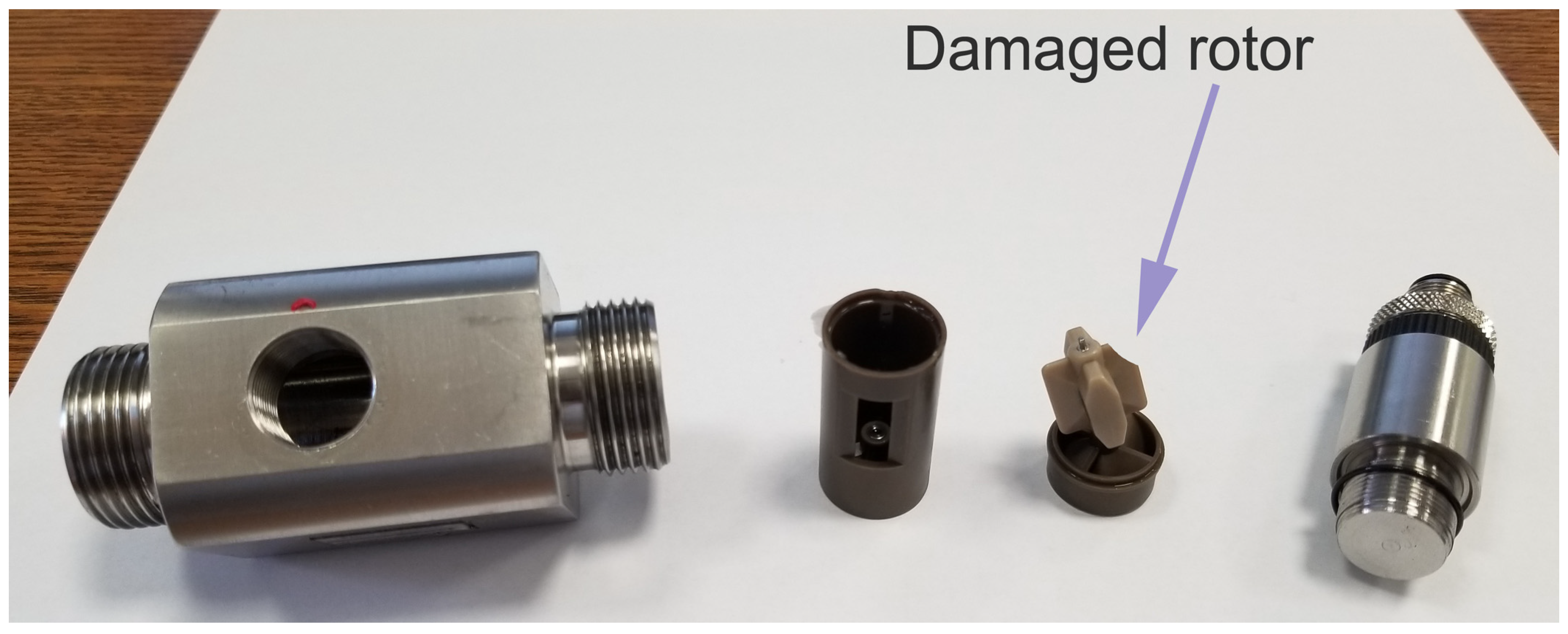
To begin with, the flowmeter is disassembled to identify the defective part. As shown in
Figure 2, one can notice that the rotor of the flowmeter was damaged during a faulty maintenance procedure, leading to the damage of one of its blades.
The rotor’s geometry is intricate, and even the slightest deviations from it can significantly affect the flowmeter’s measurement accuracy. In this instance, repairing the rotor is not feasible, and the component is not available on the market as a replacement part; the only viable option is to manufacture a new rotor with identical geometry. To economically produce the new rotor while minimizing material consumption, the Masked Stereolithography Apparatus (MSLA) additive manufacturing technology was chosen. This technology allows for the fabrication of details with dimensions as small as 50 µm and employs plastic materials resistant to the oils used in hydraulic drive systems (HDS) and their additives. Given the complexity of the flowmeter rotor’s geometry, and the limitations of measurement tools to fully describe this geometry, the principle of reverse engineering was adapted to this case.
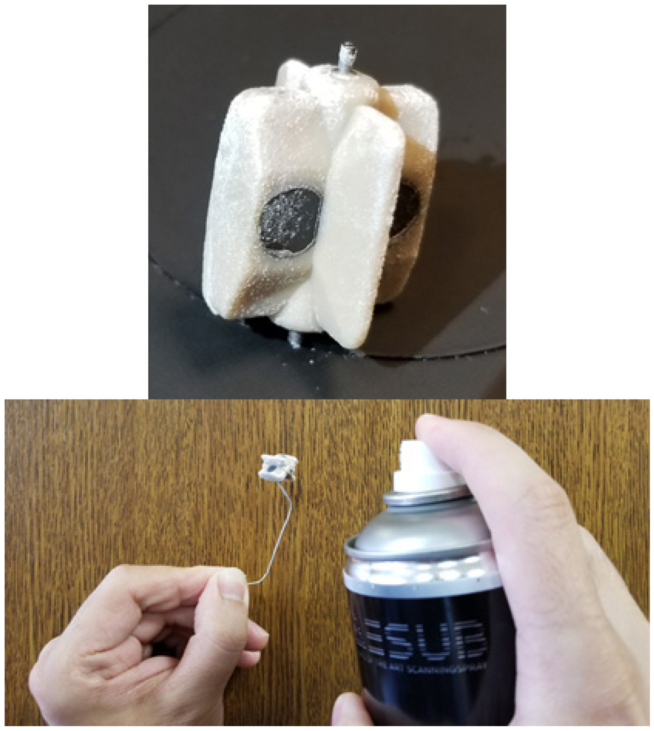
To commence, the flowmeter’s rotor was disassembled and coated with “AESUB-SPRAY-Black” (produced by AESUB, located in Recklinghausen, Germany), as shown in
Figure 3. This temporary coating transforms glossy surfaces into matte ones that do not reflect light. Such a procedure is necessary because 3D scanners with structured light technology cannot effectively scan glossy surfaces. Approximately 2 to 4 h after the application, which allows sufficient time for the 3D scanning of the rotor, the matte layer, with a minimal thickness of 5–20 µm, sublimates. Consequently, the coated component requires no further cleaning processes.
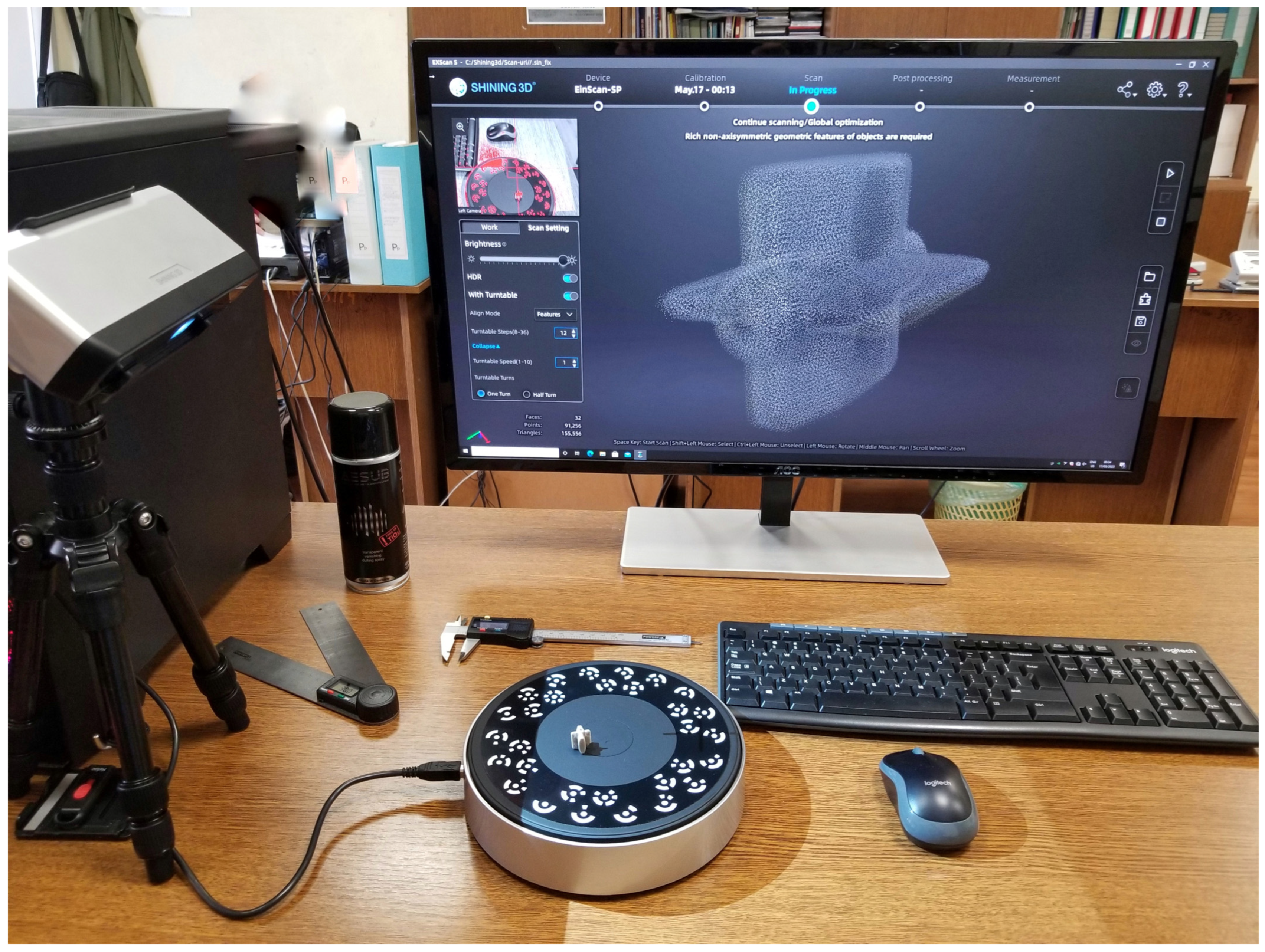
Following the application of the thin matte coating to the rotor, it was subjected to 3D scanning using the “EinScan-SP V2” scanner, manufactured by SHINING 3D, headquartered in Hangzhou, China, as depicted in
Figure 4. This scanner generates a virtual point cloud, spatially arranged, which approximates the geometry [
35] of the rotor.
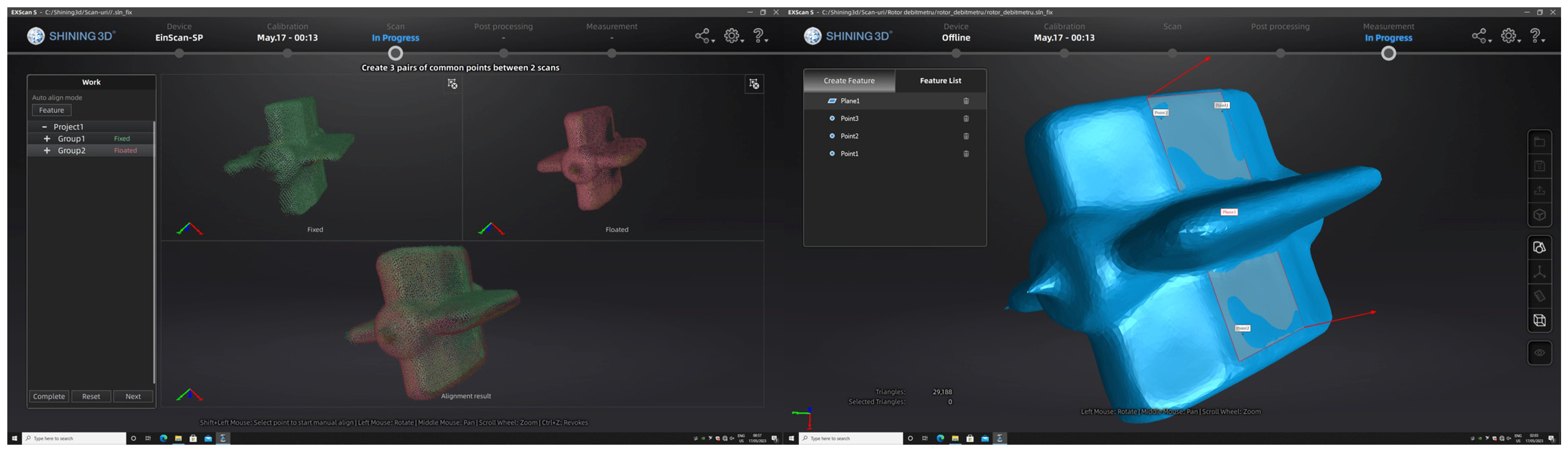
The 3D scanning of the rotor was conducted in two distinct positions to enable comprehensive coverage of all surfaces. Subsequently, the two resulting geometries were aligned and transformed into a surface 3D model in “stl” format, as depicted in
Figure 5.
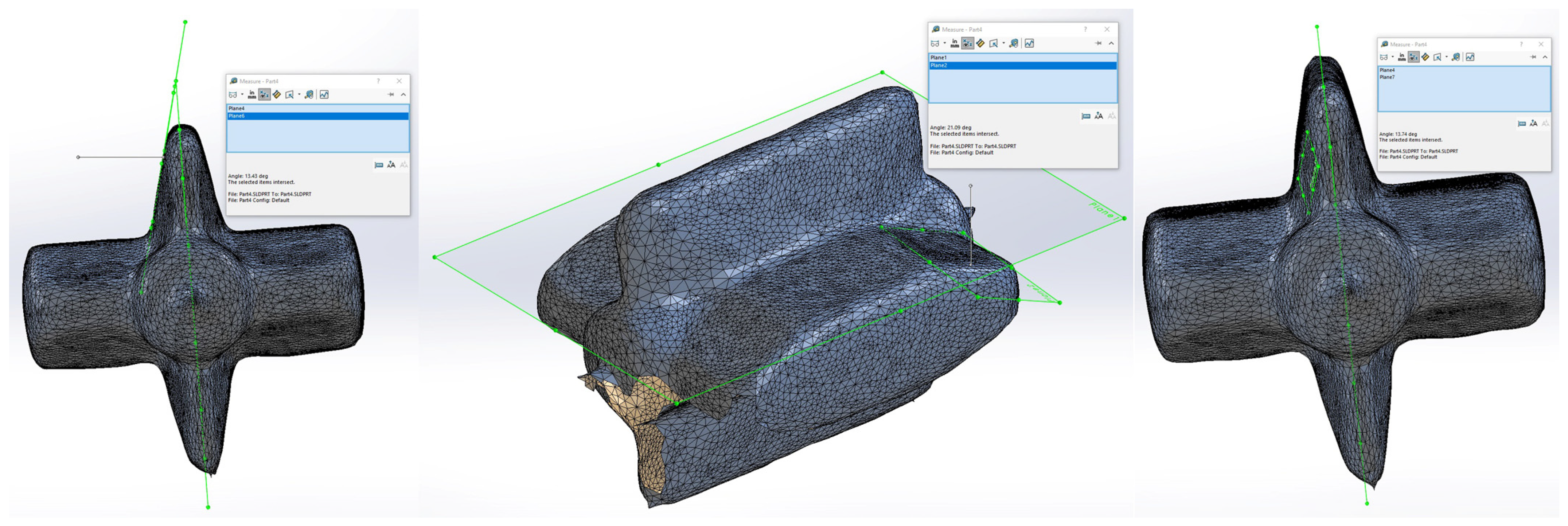
The “stl” format model resulting from the 3D scanning was imported into the parametric 3D modeling software “SOLIDWORKS 2023 SP 1.0.” Within this software, various virtual measurements, as depicted in
Figure 6, were performed, measurements that would be physically unattainable.
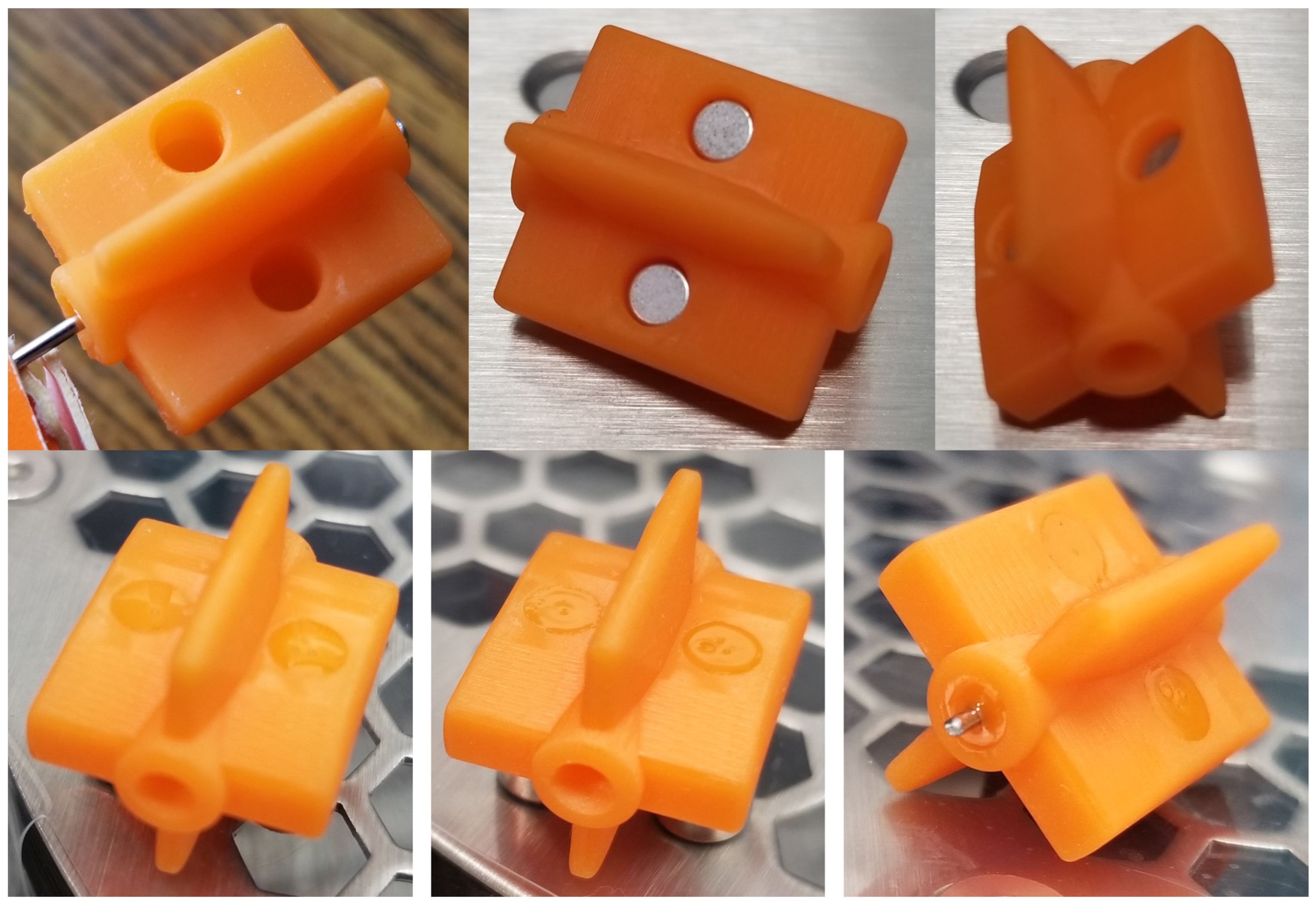
With the precise dimensions of the rotor, obtained through physical and virtual measurements (lengths, diameters, and angles), an accurate 3D model of the rotor was meticulously created in “SOLIDWORKS.” This model, as showcased in
Figure 7 from various angles and cross-sections, illustrates how space was intentionally allocated for the incorporation of magnets and the shaft, ensuring their permanent integration into the rotor.
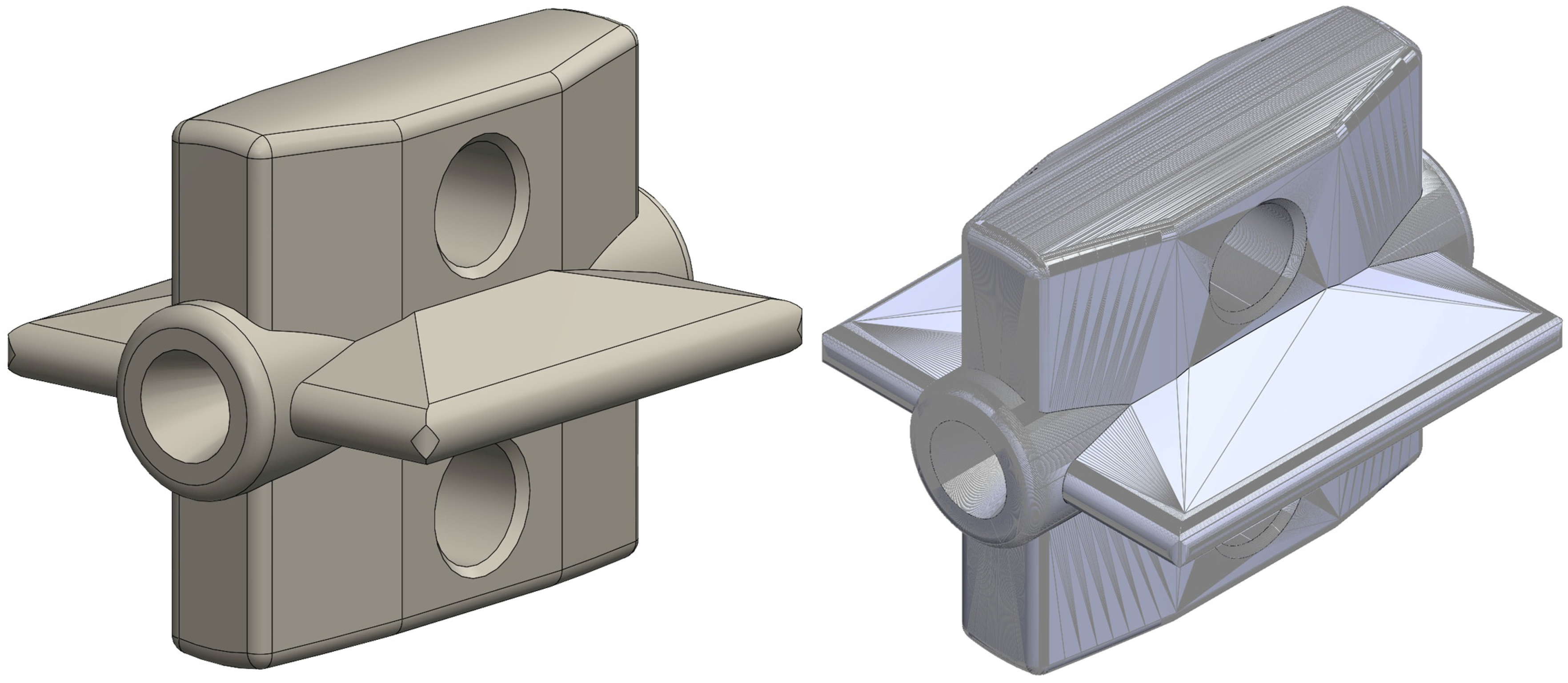
Figure 8 demonstrates how the precise “stl” model resulting from the 3D modeling in “SOLIDWORKS” faithfully replicates the geometry of the accurate 3D model.
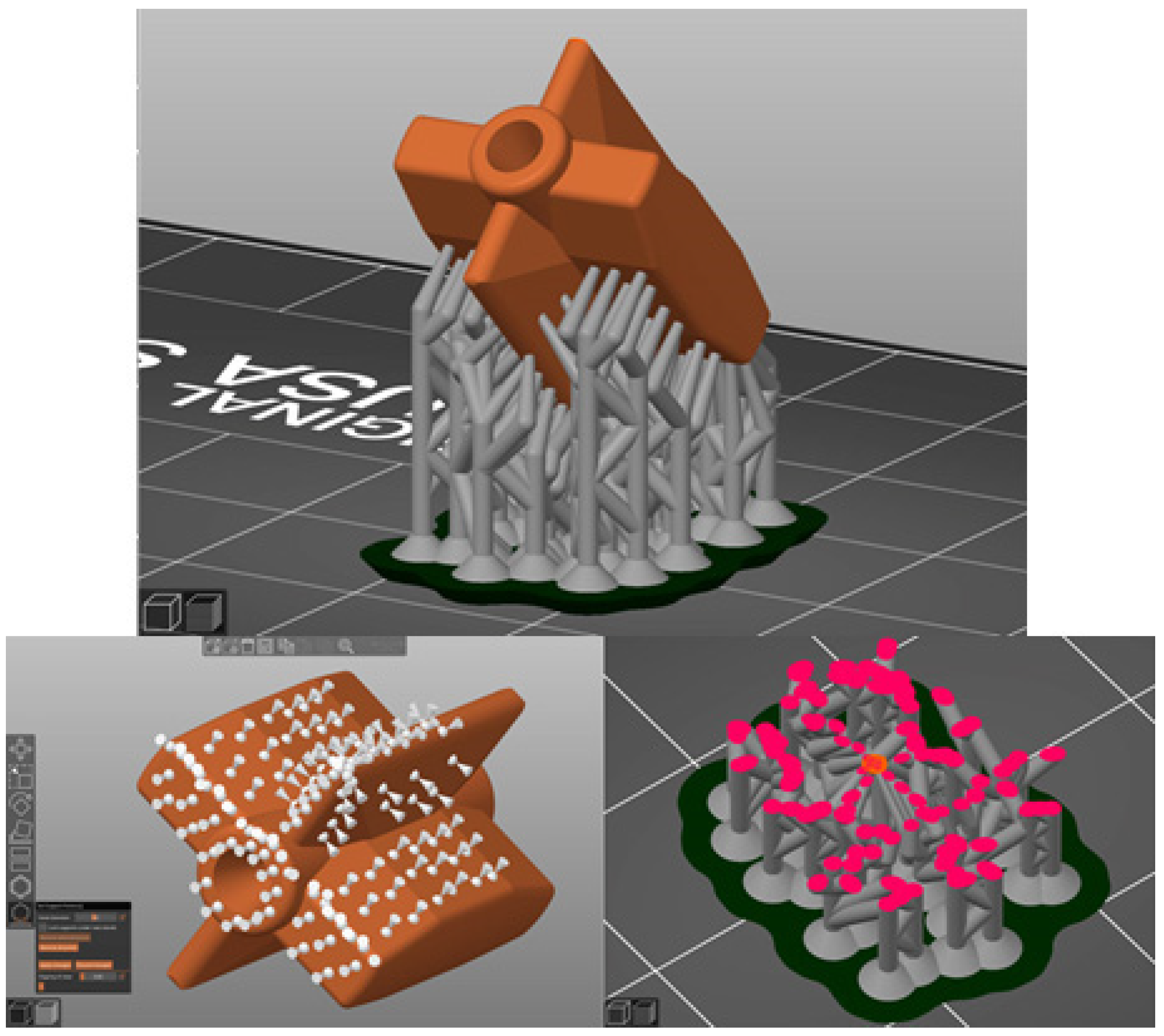
By importing the precise “stl” model into “PrusaSlicer v 2.6.0” (the slicer software for the 3D printer Prusa SL1S), support structures were added to the model and converted into machine code.
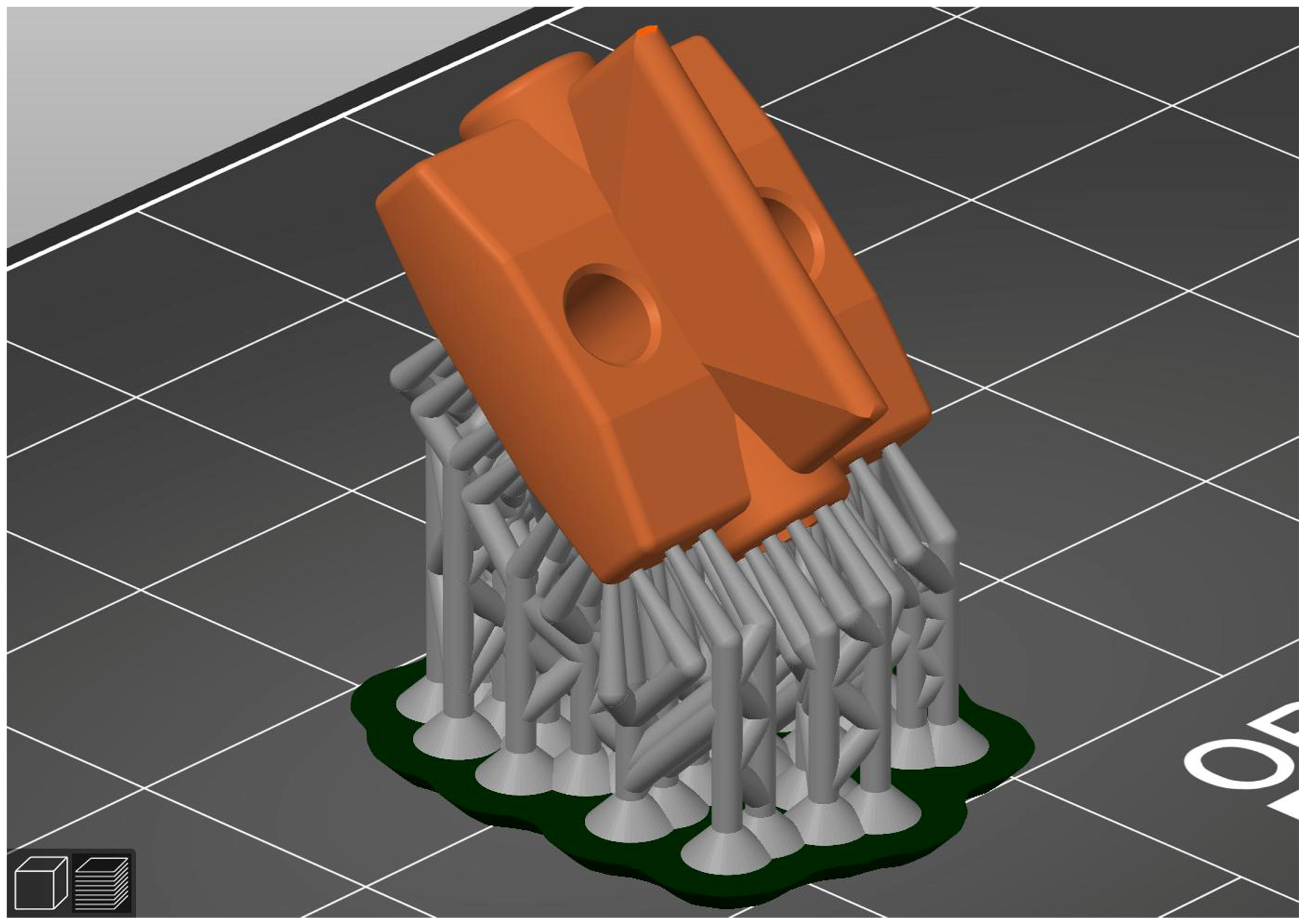
Figure 9 illustrates how support was manually applied to the rotor, with a high-density configuration to prevent deformation during the printing process [
36] (
Figure 10). This step, the conversion into machine code within the 3D printer’s slicer software, is a critical one and necessitates careful planning during the creation of the accurate 3D model. The orientation of the part must ensure that no voids are formed due to internal cavities during printing, and additional support must be provided for the initial layers of the printed component.
To address the challenge of local deformation at support junctions in parts printed using MSLA technology, several effective strategies can be applied. Among these, the authors resorted to optimizing support structures by minimizing their contact points with the printed part, using appropriate support structures to alleviate stress concentration, adjusting the print orientation and placement to strategically position support contact points, varying support thickness at critical junctions, implementing adaptive algorithms to dynamically adjust support structures based on part geometry, and employing post-processing techniques like sanding or polishing to smoothen affected areas. These combined strategies tailored to the specific part’s requirements successfully mitigate local deformation at support junctions, enhancing the quality of parts produced through MSLA technology.
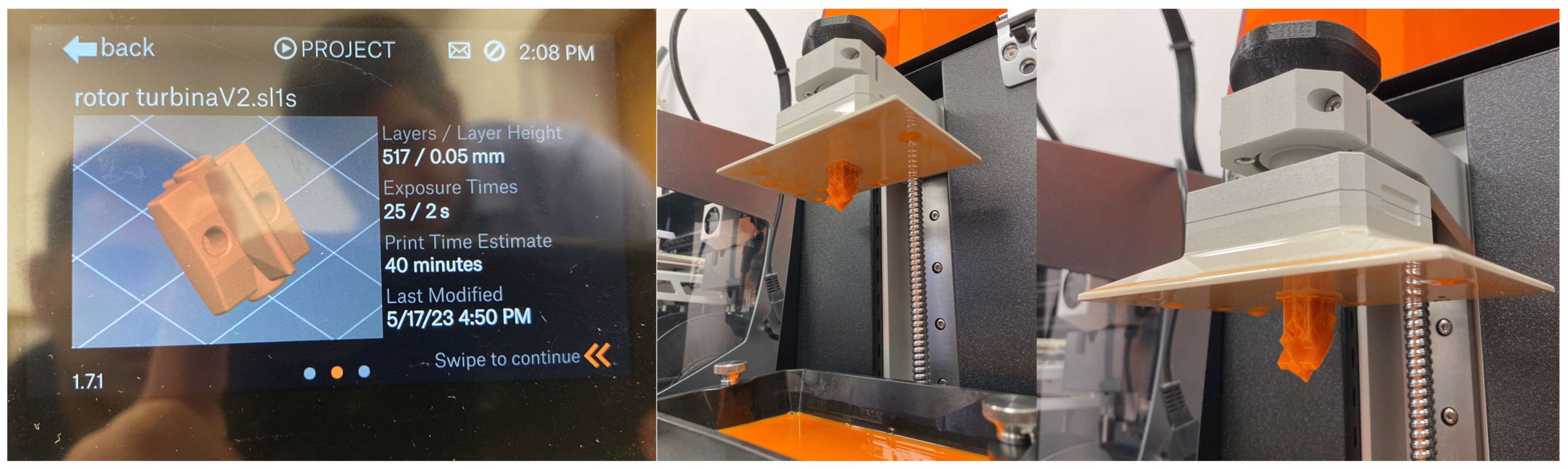
The machine code generated by the slicer is fed into the 3D printer, the “Prusa SL1S.” The printer incrementally solidifies successive layers, each with a thickness of 50 µm, using ultraviolet (UV) radiation, which is selectively blocked by a liquid crystal display (LCD) screen. After approximately 40 min, the result is a semi-solidified rotor, as shown in
Figure 11.
To fabricate the rotor using the MSLA technology, several types of photo-polymeric resins, manufactured by Prusa Research a.s., located in Prague, Czech Republic, were tested: ceramic resins, due to their improved mechanical strength and rigidity; elastic resins, known for their toughness and ability to deform elastically under high stress [
37]; and tough resins, which, while not excelling in any particular property, are generally suitable for various applications. Ultimately, a tough resin was chosen for the rotor’s production. This resin withstands mechanical stresses with a minimum value of 41 MPa/mm², temperatures up to 95 °C, and exposure to chemicals found in hydraulic fluids. Ceramic resins were excluded due to their high density, which increases the rotor’s moment of inertia and the possibility of rotor fragments detaching and potentially damaging components within the hydraulic circuit if certain particles pass through filters due to their hardness. Elastic resins were also excluded because, with increasing temperature, their flexibility significantly improves, and centrifugal forces can alter the part’s geometry, causing deformation until the rotation speed decreases.
The use of plastic materials in remanufacturing implicates several factors for long-term performance and durability compared to the original materials. These considerations revolve around material selection, environmental conditions, structural integrity, compatibility, wear, fatigue, and the quality of additive manufacturing. While some engineering-grade plastics like nylon or PEEK can offer high resistance to chemicals and excellent mechanical properties, making them suitable for certain applications, they may not withstand high temperatures, abrasive conditions, or constant stress as well as metals. The structural differences between plastics and metals, potential material degradation in aggressive conditions, and differences in wear characteristics can impact the remanufactured component’s longevity. The quality of the 3D printing process also influences durability, as inadequate printing could result in weak points or inconsistencies. Weighing these factors against specific application requirements and operational demands is crucial. While plastics might provide comparable durability and performance in some instances, metal components could offer superior durability, especially in high-stress, high-temperature, or chemically aggressive environments. In the case analyzed, the initial hydraulic part (flowmeter rotor) was made of plastic material, the same as the one produced by additive manufacturing.
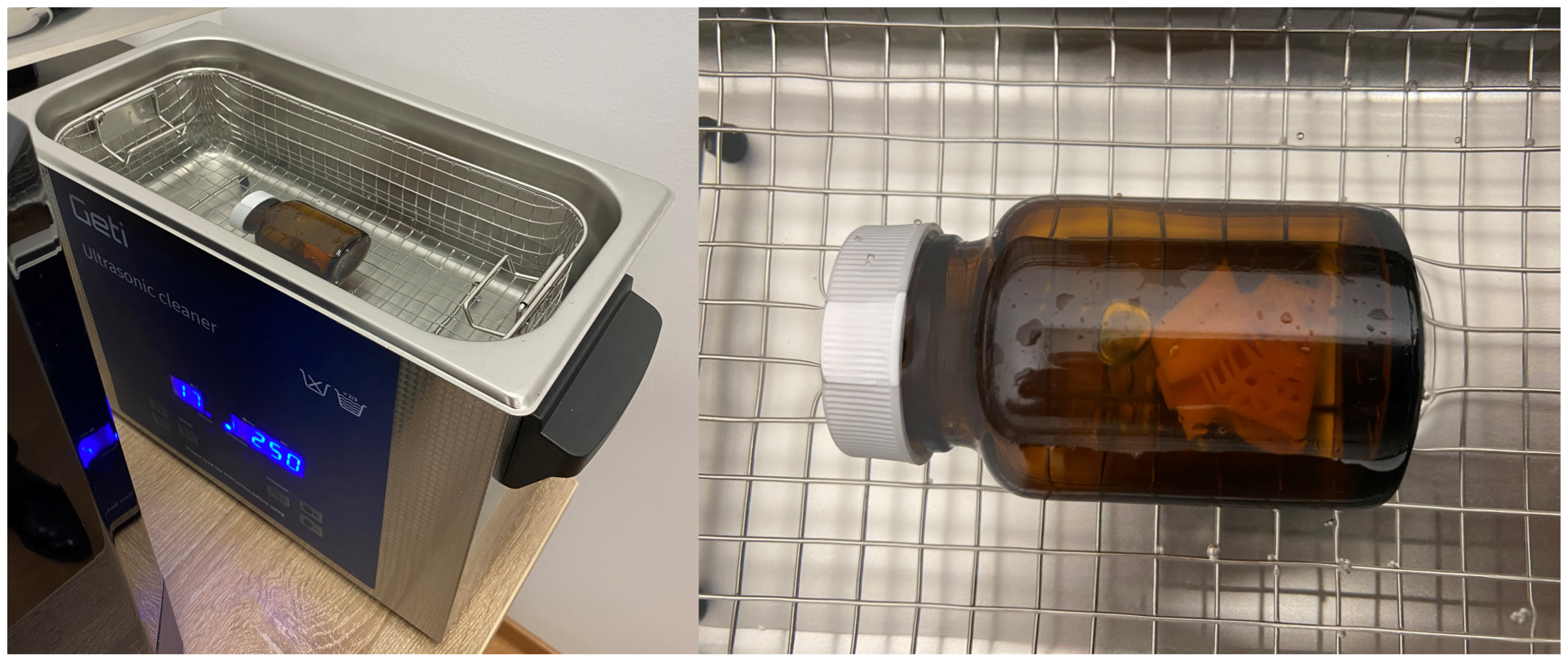
Following the 3D printing process, the rotor was immersed in an ultrasonic bath that generates cavitation. Subsequently, using isopropyl alcohol, the rotor was cleaned of any unhardened resin residue (
Figure 12). To prevent contamination of the ultrasonic bath with resin, it was filled with water, and the rotor was placed in a glass container filled with isopropyl alcohol. After cleaning the rotor, it was removed from the isopropyl alcohol container, and the dissolved resin in the container was cured using ultraviolet radiation. Finally, with the aid of a sieve, the cured resin in the container was separated from the isopropyl alcohol, which can be reused for the same process numerous times.
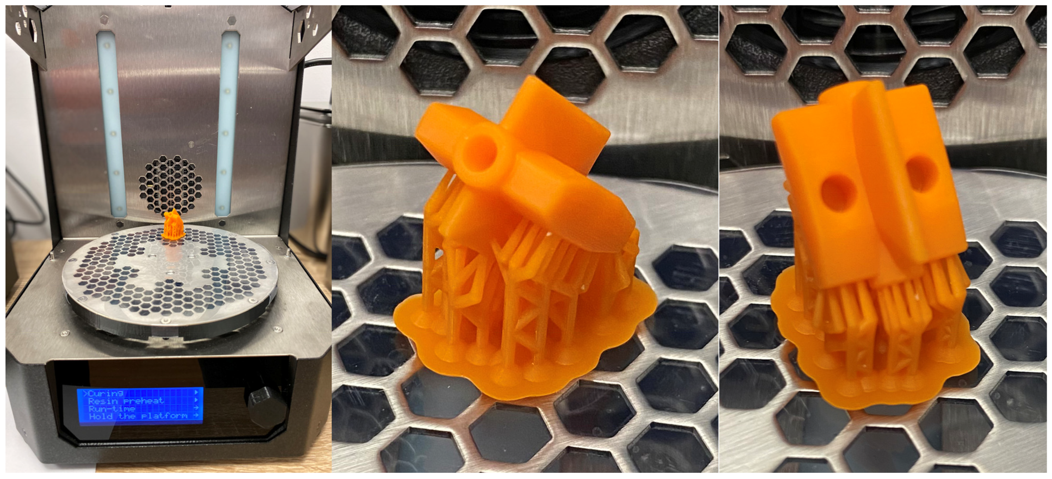
As the rotor does not yet attain its final mechanical strength at the end of the 3D printing process, it requires additional curing with ultraviolet (UV) radiation in the multifunctional station “Prusa CW1S” (
Figure 13) for a minimum of 6 min, in at least two different positions. In the same figure, one can notice that the support structure for the part has not yet been removed. The removal of the support structure will be carried out once the part reaches its final mechanical strength. Removing the support structure before the final curing can lead to non-uniform release of internal stresses within the material, potentially causing deformation in the rotor at the end of the curing process.
Following the removal of the support structure and the post-processing of the rotor, two FeBNd magnets and a chromed shaft were added to it. These components were then permanently integrated into the rotor’s structure (
Figure 14). Through the aforementioned operations, the rotor can be deemed as finalized.
A notable difference can be observed between the original flowmeter rotor (the damaged one) and the one produced using additive manufacturing, particularly regarding the size of the magnets. In the original rotor, the magnets were cylindrical in shape with a diameter and length of 5 mm each, whereas in the new rotor, they are also cylindrical but with a diameter of 3 mm and a length of 3 mm. To ensure a similar signal amplitude for the “Hall” sensor within the flowmeter, and considering that the new magnets are stronger and placed one millimeter farther from the sensor, the magnetic field strength of the original magnets was compared with that of the new magnets using the deformation of an elastic spring. It was found that the elastic spring exhibited a slightly greater elongation when subjected to the new magnets’ magnetic field.
3. Results
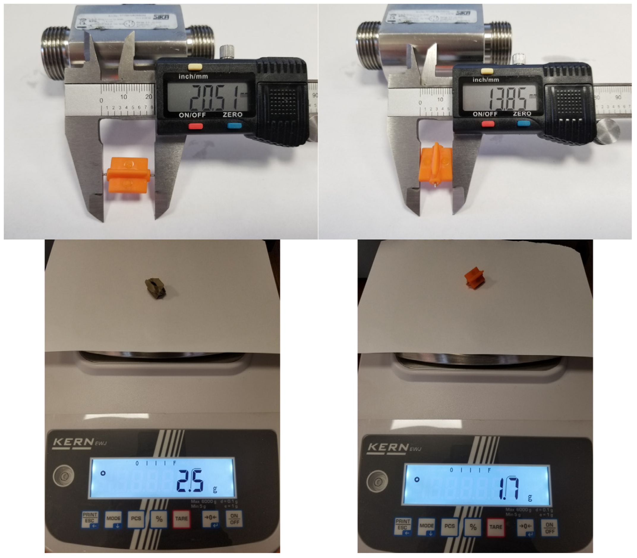
At the end of the additive manufacturing process, the new rotor was subjected to measurements, weighed, and compared with the defective one (
Figure 15). These operations revealed that the physical dimensions of the new rotor exhibit minimal dimensional deviation, approximately 0.01 mm (most likely a measurement error), and its weight is lower due to the reduced volume of the magnets used. The reduced mass of the rotor and the arrangement of the magnets one millimeter closer to the instantaneous center of rotation of the rotor reduce the moment of inertia, resulting in a faster response of the flowmeter to flowrate variations.
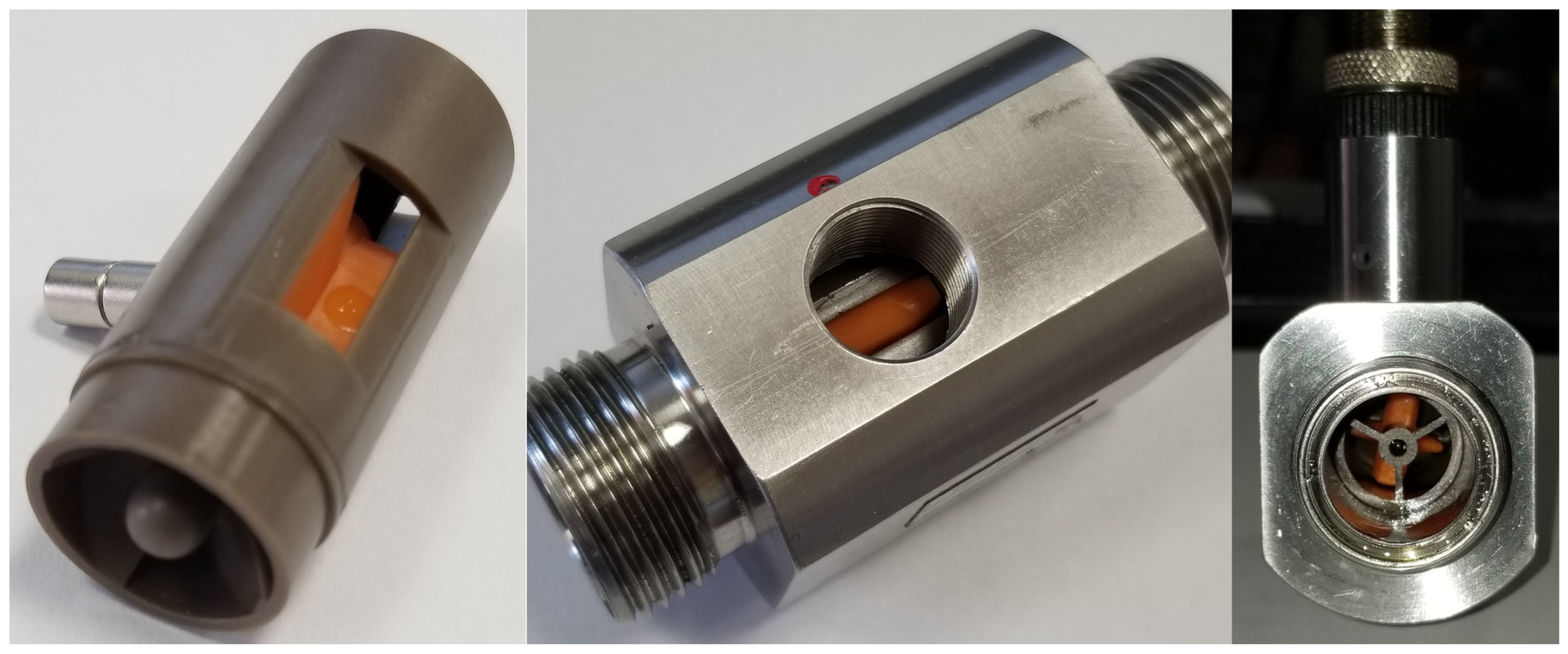
Figure 16 illustrates the assembly process where the rotor has been mounted within the subassembly, and the flowmeter has been fully assembled.
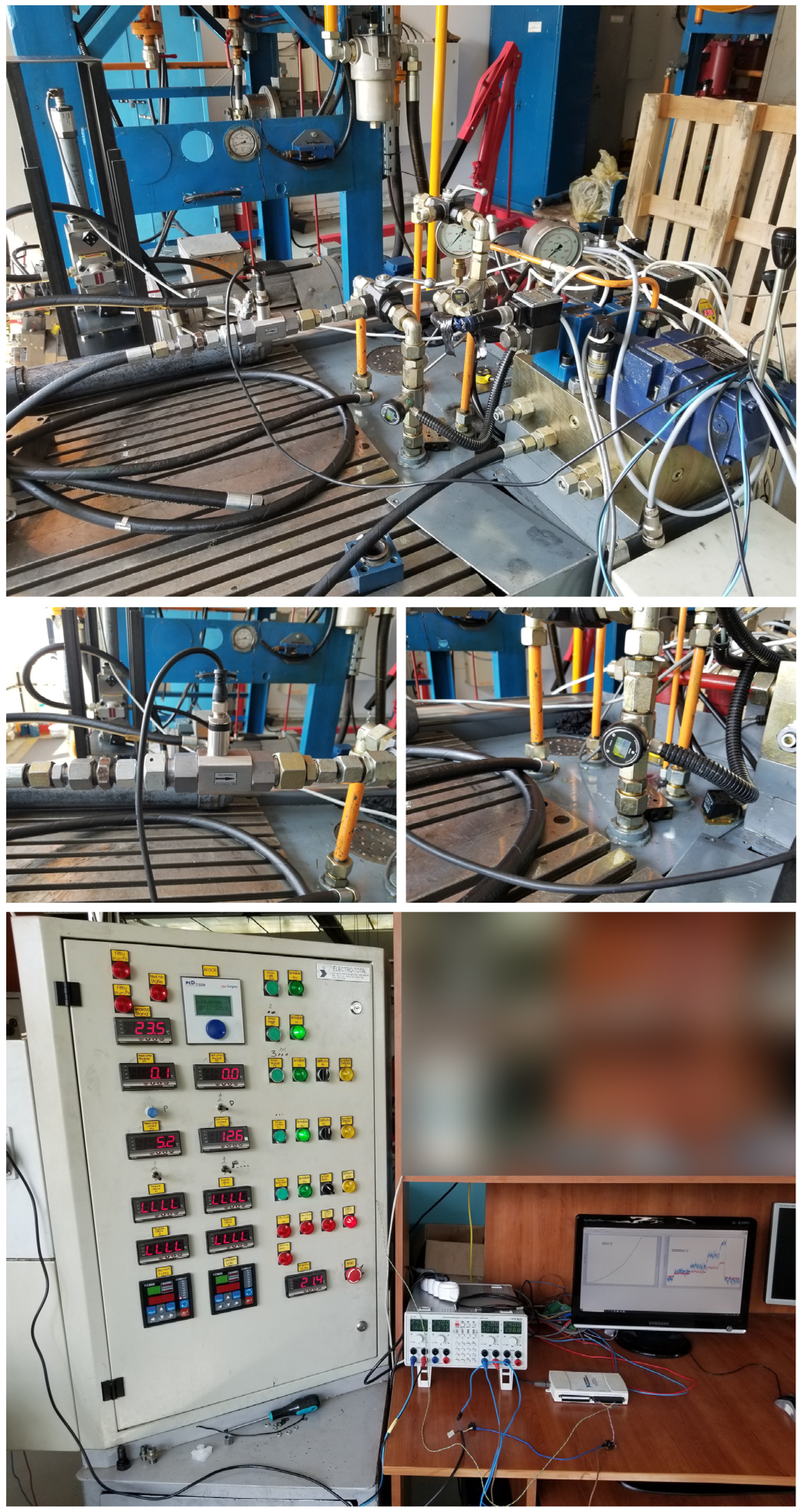
Following the assembly of the flowmeter, functional tests were conducted in the General Hydraulics Laboratory of IHP using the servo-technical test stand facilities. These tests involved connecting the remanufactured flowmeter in series with another flowmeter (
Figure 17)—a flowmeter with higher precision—and comparing the values transmitted by them using the “LabVIEW” (2019) data acquisition and processing software. The experimental setup included a variable flow control pump and control system, the remanufactured flowmeter, the reference flowmeter, a data acquisition board NI 6259, a 24 V power supply, a computing system, and a control panel with digital displays.
Through this setup, a hydraulic fluid with variable flowrates ranging from 3.2 to 17.8 L/min (
Figure 17) was circulated. On the panel with digital displays, it can be observed that, at a flowrate of 12.6 L/min, the pressure drop across the two flowmeters is 5.2 bar.
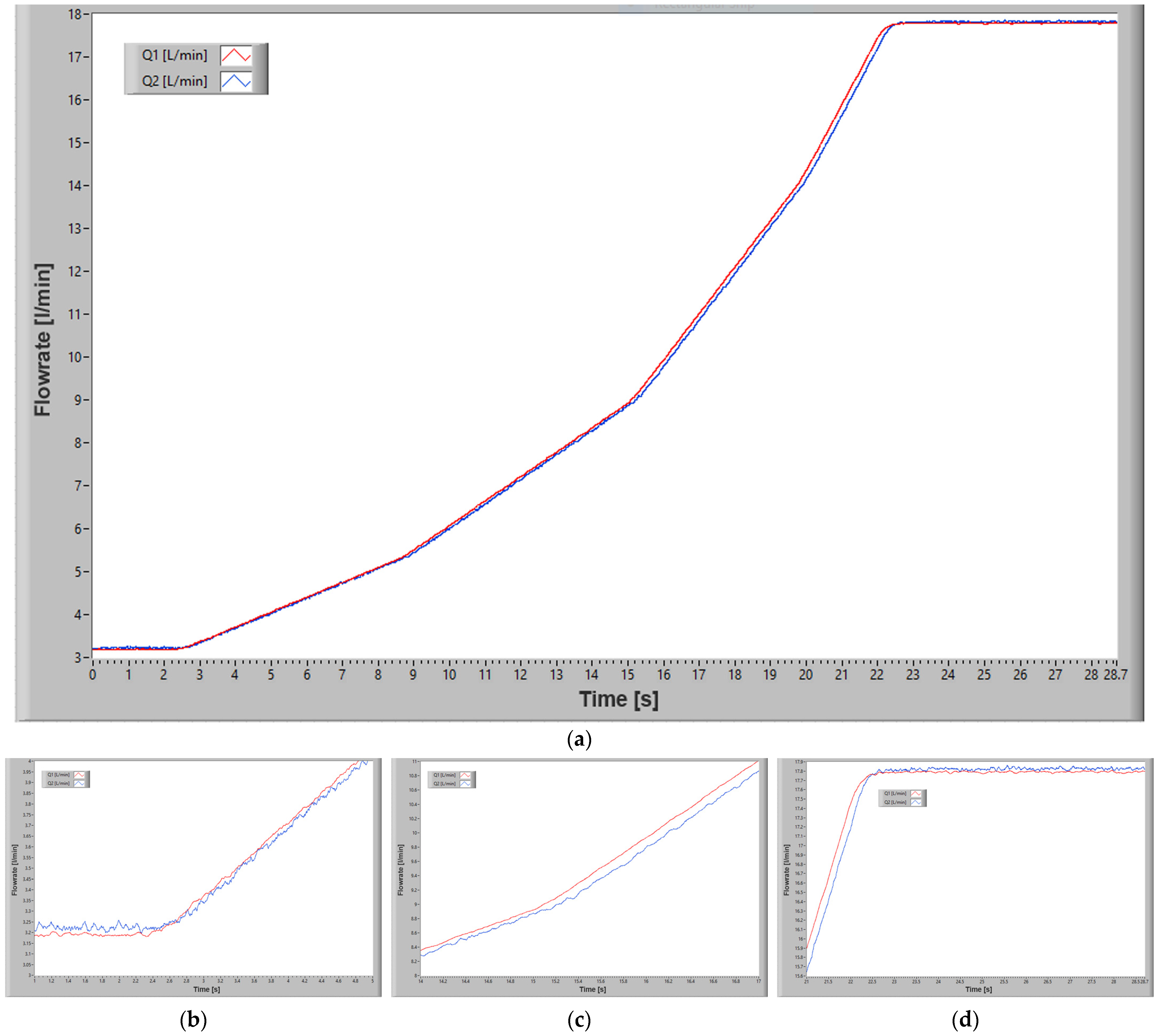
The experimentation lasted 28.7 s, and
Figure 18 presents the time variation of the flowrates for the two flowmeters (a) and details of this variation for three distinct periods: the beginning of the measurements (b), the end of the measurements (d), and the middle of the measurements (c). The red curve (Q1) represents the flowrate of the reference flowmeter, while the blue one (Q2) represents the flowrate of the remanufactured flowmeter. In the same figure, one can notice that, when changing the flowrate value, there is a small lag (delay) between the two flowrates, which is caused by the moment of inertia of the remanufactured flowmeter’s rotor. Additionally, on the linear portions of the curve, the flowrate value of the remanufactured flowmeter is slightly higher, by approximately 0.05 L/min, compared to the reference flowmeter’s value. This offset should be electronically applied in the data acquisition software afterward to ensure both flowmeters display identical values (calibration purposes).
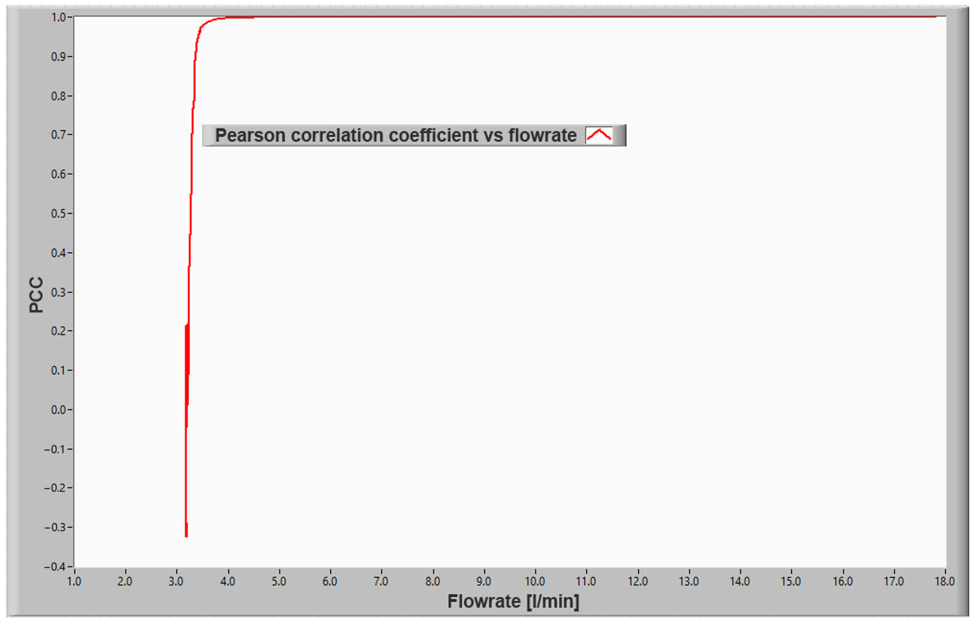
Figure 19 displays the linear correlation between the two flowrates. If the correlation coefficient is close to zero, it indicates a lack of significant linear correlation between the two variables. Conversely, a correlation coefficient close to −1 or +1 signifies a strong linear correlation between the variables. The closer the correlation coefficient is to −1 or +1, the stronger the correlation is.
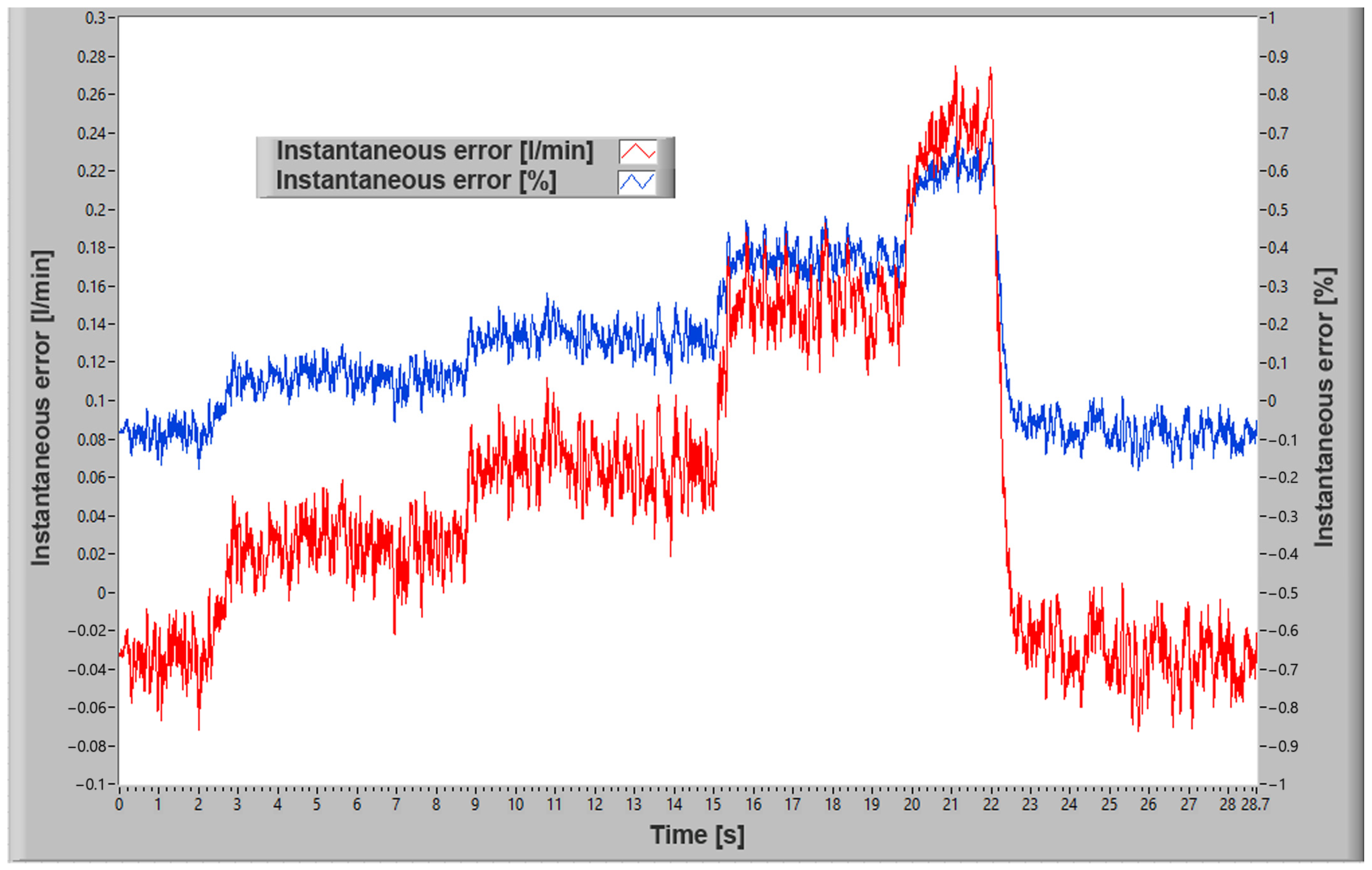
Comparing the measurement error of the remanufactured flowmeter with the reference flowmeter (
Figure 20), there is a deviation of +0.28 and −0.08 L/min (absolute 0.36 L/min), with the absolute percentage error being less than 1% (+0.7% and −0.2%). These deviations primarily arise due to the lag between the two measurements.
Based on the functional tests, one can conclude that the repair was successfully executed, as the measurement error of the remanufactured flowmeter falls within the specified limits provided by the manufacturer (±1% of the measurement range).
4. Discussion
The costs associated with remanufacturing through additive manufacturing and reverse engineering compared to manufacturing new hydraulic drive system components vary based on diverse factors. This comparison involves material expenses, labor costs, equipment investments, design and engineering outlays, quality control needs, and sustainability considerations. Remanufacturing entails material costs primarily linked to additive manufacturing materials, while new manufacturing uses raw materials that might be pricier. Labor expenses involve skilled workers for scanning, 3D printing, and quality control in remanufacturing, versus the need for labor in traditional manufacturing processes. Equipment costs for both approaches are substantial, with remanufacturing requiring investments in 3D scanning and additive manufacturing machines. Design and engineering costs encompass reverse engineering and adapted designs for remanufacturing compared to the design expenses of new manufacturing. Quality control is vital in both processes but follows varied protocols. Remanufacturing is often viewed as more sustainable, considering its reduction in waste and energy usage compared to new manufacturing. However, higher initial investment costs for equipment and skilled labor might be incurred. Ultimately, the cost-effectiveness of remanufacturing versus new manufacturing hinges on factors like component complexity, production scale, materials used, and technologies employed. Other influential factors could include sustainability goals, component availability, and lead times beyond the sole consideration of cost.
To mitigate the high concentration of local (micro) deformation and distortions in parts manufactured using the MSLA additive manufacturing technique, various strategies can be implemented. Optimizing print settings, adjusting exposure time, layer height, and curing settings, tailored to the specific part’s requirements, can mitigate distortion. Employing suitable support structures can offer stability, significantly reducing deformation risks, especially in complex parts. Selecting resins with lower shrinkage rates and low viscosity contributes to less distortion. Maintaining a controlled printing environment prevents extreme temperature variations that can cause warping. Post-curing techniques and calibration procedures further rectify distortions. Implementing these strategies while fine-tuning printing parameters allows for meticulous adjustments to achieve the desired accuracy and quality in the final printed components.
The environmental impact and carbon footprint reduction achieved through remanufacturing via additive manufacturing and reverse engineering compared to traditional methods are considerable. The practice significantly reduces material consumption by reusing non-defective components and producing only the necessary parts, curbing the energy-intensive processes associated with new material extraction. Remanufacturing, particularly through additive manufacturing, reduces waste generation by using only the required materials, lessens energy consumption in the layer-by-layer manufacturing process, and diminishes transportation emissions by producing parts locally. These practices adhere to circular economy principles, extending component lifecycles and diverting parts from landfills. While additive manufacturing and reverse engineering have energy requirements, their impact is significantly offset by material savings, waste reduction, and the utilization of recyclable materials, aligning with sustainability goals and contributing to a more environmentally friendly manufacturing approach.
While plastic materials are used in this research due to their versatility and availability, it is evident that metallic alloys are preferred for remanufacturing hydraulic drive system components, primarily due to their superior mechanical properties. However, the additive manufacturing process can be slightly adapted to accommodate these metal alloys, thereby broadening the scope of components eligible for circular-economy-driven remanufacturing. The adoption of additive manufacturing techniques with metal alloys significantly enhances the range of hydraulic drive system components that can be feasibly remanufactured. The improved mechanical and physical characteristics of these alloys make them particularly suitable for remanufacturing applications, offering enhanced performance and durability. The integration of metallic alloys into the remanufacturing process using additive manufacturing and reverse engineering brings forth various challenges that demand careful consideration and innovation for effective solutions. Challenges such as material compatibility, printability, post-processing, cost considerations, quality assurance, regulatory compliance, and material recycling are anticipated. Addressing these challenges includes carefully selecting alloys that closely match the properties of the original components, optimizing printing parameters, integrating necessary post-processing steps, efficient material sourcing, implementing quality assurance measures, ensuring regulatory compliance, and developing recycling processes for metallic materials. By navigating these challenges and staying abreast of advancements in additive manufacturing and metallurgy, the successful integration of metallic alloys in the remanufacturing process is achievable, offering more durable, high-performance components that align with sustainability goals in hydraulic drive systems.
The scalability of remanufacturing through additive manufacturing and reverse engineering is highly dynamic and influenced by technological advancements in the field. Advancements in additive manufacturing technology, materials, and precision, along with multi-material printing capabilities, are poised to significantly enhance scalability. The rapid improvements in printing speed and efficiency, expanded material options, and increased precision in reverse engineering are all set to improve the scalability of remanufacturing operations. Moreover, standardization, certification, and potential cost reductions are expected to further encourage the widespread adoption of sustainable manufacturing practices as these technological advancements continue to evolve.
This article delineates an innovative framework for remanufacturing hydraulic drive system components, rooted in circular economy principles and sustainability through the integration of advanced additive manufacturing and reverse engineering techniques. This application-specific focus on remanufacturing hydraulic flowmeter components marks a notable deviation from the broader spectrum covered in the research reflected by the reference section. The references extensively explore various facets of additive manufacturing, encompassing materials (references [
2,
4,
11,
19]), processes (references [
1,
6,
8,
25]), and applications across diverse fields such as dentistry, biomaterials, robotics, and mechanical design. Additionally, the references elucidate the multifaceted aspects of reverse engineering, including its methodologies (references [
14,
15,
16,
17]) applied in different sectors like mechanical design, dentistry, and material science. The novelty in the article lies in the detailed account of applying these advanced technologies specifically to the remanufacturing of hydraulic flowmeter components. It highlights a meticulous examination of the remanufacturing process, outlining the integration of additive manufacturing technology and 3D scanning to restore a damaged flowmeter, which is not presented in the scientific literature. The article underscores a commitment to repurposing non-defective components, fostering a closed-loop system to minimize waste generation and reduce the environmental impact associated with hydraulic system maintenance. This targeted application differs from the broader discussions in the references, which cover a wide array of applications and technologies related to additive manufacturing and reverse engineering but lack the detailed, specific application within the hydraulic systems remanufacturing sector. In essence, while the references provide comprehensive insights into the advancements, materials, methodologies, and broader applications of additive manufacturing and reverse engineering, this article stands out due to its focused, in-depth application within the hydraulic systems remanufacturing sector. It presents a practical example of how these cutting-edge technologies are leveraged to promote sustainability, circular economy principles, and resource efficiency within a specific industrial domain. This specificity and detailed insight into the application of these advanced methods to hydraulic systems is a distinctive feature not extensively covered in the more generalized discussions found in the scientific literature.


 ,
, 


