
Poka Yoke in Smart Production Systems with Pick-to-Light Implementation to Increase Efficiency


Abstract
:1. Introduction
1.1. Importance of Our Study
1.2. Defending the Model
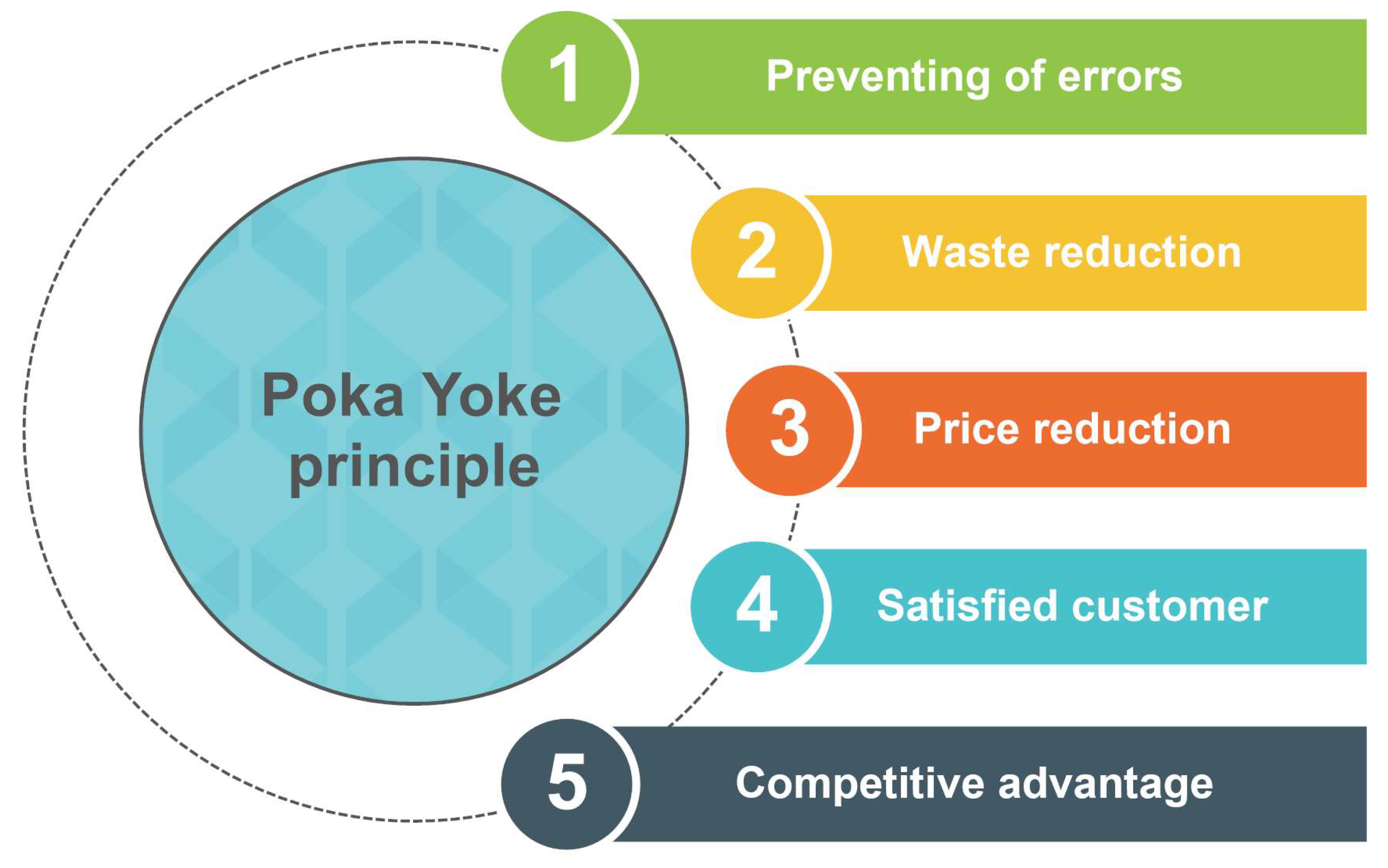
1.3. Advantages of Poka Yoke with Pick to Light
1.4. Rationale and Objectives
- Investigating the theoretical underpinnings of Poka Yoke and its compatibility with modern manufacturing principles;
- Assessing the practical implications and advantages of combining Poka Yoke with the Pick-to-Light system;
- Providing actionable insights and recommendations for manufacturers looking to implement this model.
1.5. Poka Yoke and Pick to Light
- Process errors arise from incorrect production environment design, workplace, procedures, etc.
- Errors caused by employees—the human factor is at work here.
- Implementation complexity: Designing and implementing Poka Yoke requires thorough production process analysis, potential error identification and the creation of appropriate control mechanisms. It can be time and resource-intensive.
- Changing work practices: Introducing Poka Yoke may require changing work practices and employee habits. Some employees may resist change, so providing adequate training and support for their adaptation is important.
- Integration with existing systems: In the case of smart manufacturing systems, it can be a challenge to integrate Poka Yoke with existing technologies and control systems. Ensuring compatibility and interoperability may require technical adjustments and effort.
- Implementation costs: Pick to Light can be quite expensive to implement. It requires investments in light indicators, sensors, control systems and possibly the modification of racking systems.
- Physical installation: Implementing the Pick-to-Light system requires installing light indicators on racks or shelves. The installation can be complex and requires modifications to existing infrastructure.
- Maintenance and management: The Pick-to-Light system requires regular maintenance and management. Light indicators, sensors and other components must be monitored and repaired in case of malfunctions or wear.
- Adaptation to changing needs: Intelligent manufacturing systems can change and expand, so it is necessary to ensure that the Pick-to-Light system can adapt to new requirements and extensions.
2. Literature Review
Basic Functions of Poka Yoke
- (1)
- Shutdown function;
- (2)
- Control function;
- (3)
- Warning function.
- A control device located directly at the source of the error—before the failure occurs. A typical example is a pin that prevents incorrect orientation of the workpiece from being processed. These means are often the most effective solution.
- The 100% control for detection—using a low-cost sensing device such as a limit switch. In case of the presence of any abnormality, light or sound signalling is activated.
- Immediate measures to stop the operation in the event of an error—an example is a blocking circuit that automatically shuts down the machine from operation.
- Research question 1: does the introduction of Pick to Light affect the assembly process?
- Research question 2: how do socio-demographic characteristics influence working with Pick to Light?
- Research question 3: does the number of assembly operation repetitions affect the overall assembly of the production batch?
- Research question 4: does the introduction of Pick to Light affect the overall assembly error rate?
3. Materials and Methods
- Contact means—those that touch the tested part. The most frequently used tools are limit switches and micro switches. These can track the presence of a piece, cutting tool or mould and they are special in their flexibility. They are used to ensure the interruption of the process until the given piece takes the correct position or if it has the wrong shape. The mentioned method also uses other means based on contact, such as distance switches, displacement, part, metal passage sensors, and several other mechanical solutions.
- Non-contact means—these do not require direct contact. They find their application when working with translucent, opaque and transparent pieces. Photoelectric switches can be mentioned as a type of non-contact means. These work in two ways. The first way is to work with transparent objects. In this case, two units are used, one of which sends a light beam to the other, which is its recipient. This type is either in the on state, if the light passes through the object, or in the off state if there is an obstacle in the beam’s path. The second way is the reflex type of photoelectric switch. It reacts to the presence of an object only after the reflection of a light beam from its surface.
3.1. Pick-to-Light System
- Increasing work productivity;
- Improving quality;
- Reducing the occurrence of errors to zero;
- Continuous inventory;
- Connection to ERP and warehouse systems;
- Increasing flexibility;
- Speed of new personnel training.
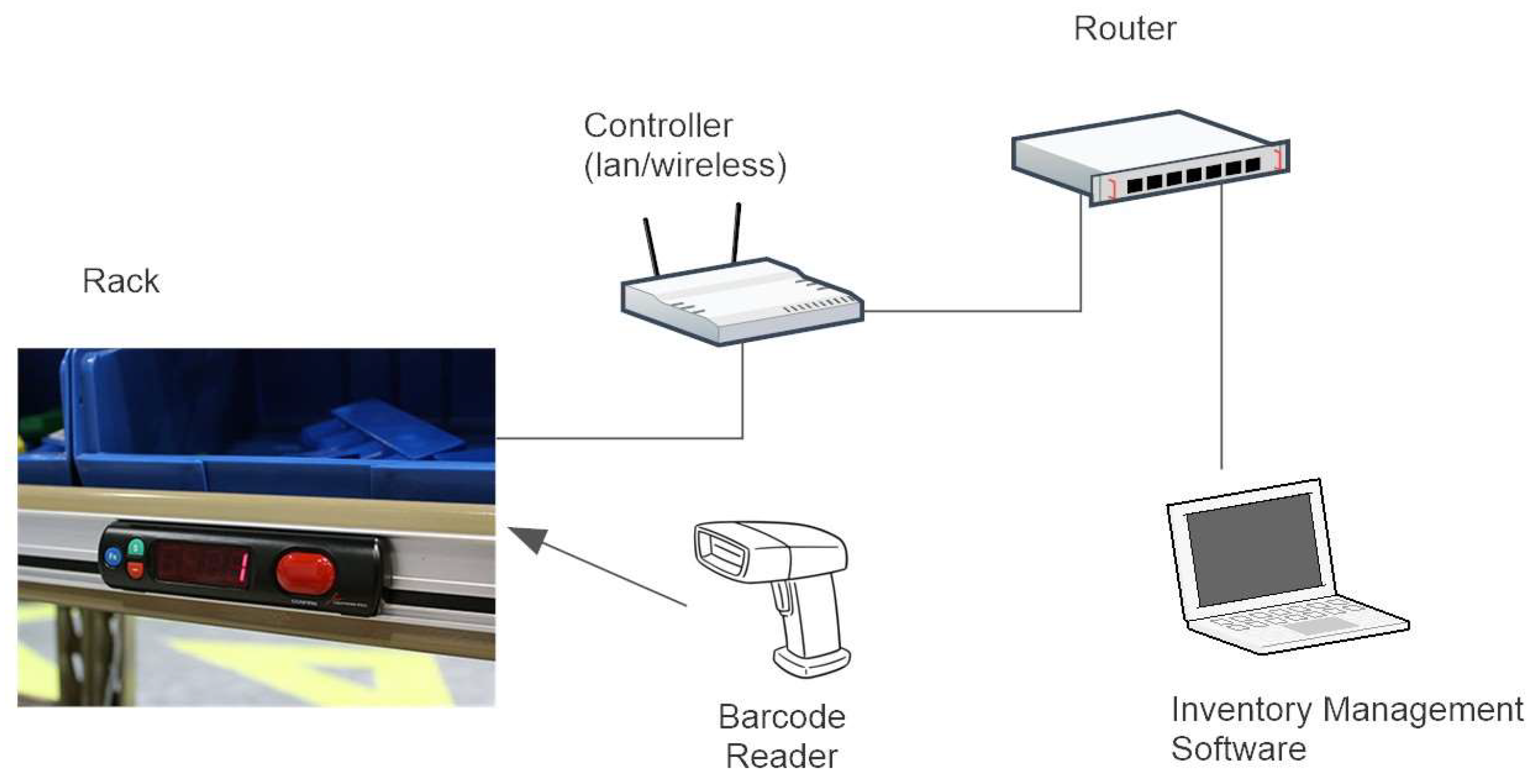
- A rack consisting of multiple Pick-to-Light units;
- A bar code reader for scanning items inserted and removed from the rack;
- A control unit/controller (network or wireless) connected to the Pick-to-Light system;
- A router or network hub;
- A remote PC installed with real-time material inventory management software.
- Error identification and indications synchronization: Create a communication interface between the Poka Yoke and Pick-to-Light systems to exchange information about identified errors and requirements for picking goods. For example, suppose the Poka Yoke system detects an error in the assembly process. In that case, it can inform the Pick-to-Light system so that the corresponding indicators show the operator that the item is not needed or is incorrect.
- Education and training of employees: Employees should be trained and educated about the functionality of both systems and how to work with them properly. They must be informed on interpreting indications, recognising errors, and taking the correct steps to repair or select items.
- Integration with the central control system: Poka Yoke and Pick-to-Light systems should be integrated with the central control system of the intelligent manufacturing system. This ensures coordination and synchronization between production processes, error identification, selection indications and other aspects of the system.
- Performance monitoring and analysis: Systems should be able to collect performance data such as picking accuracy, error response time, time statistics and other relevant data. These data should be analysed and used to identify process improvement and optimization opportunities.
3.2. Procedure for Implementing the Poka Yoke Method Using Pick to Light
- Optical-reflective sensors with LED indicators: These sensors are equipped with 2 LEDs and a comparator. They emit infrared light, which bounces off objects and returns to a photodiode, allowing them to detect interruptions in the beam caused by obstructions (e.g., an operator’s hand or plastic rod). They display red and green colours, with green indicating a suitable container and red signifying the programming mode or an incorrect container. Eight such sensors are positioned in the device’s upper bars, and their sensitivity can be adjusted via a built-in trimmer on the printed circuit board.
- Control unit with display and power supply: The core of the control unit is an ATmega 128-8 bit AVR processor responsible for system operation and control. It runs the SPIDER1FINAL program developed in Bascom-AVR IDE (2.0.8.1).
- Integrated display unit: The control unit features a BOLYMIN BC1602A display, a 2 × 16 STN yellow-green display with LED backlight.
- Power supply and connectivity: The control unit is powered by a 5V/DC adapter and has ports for connecting drawers and the AC/DC adapter at the rear.
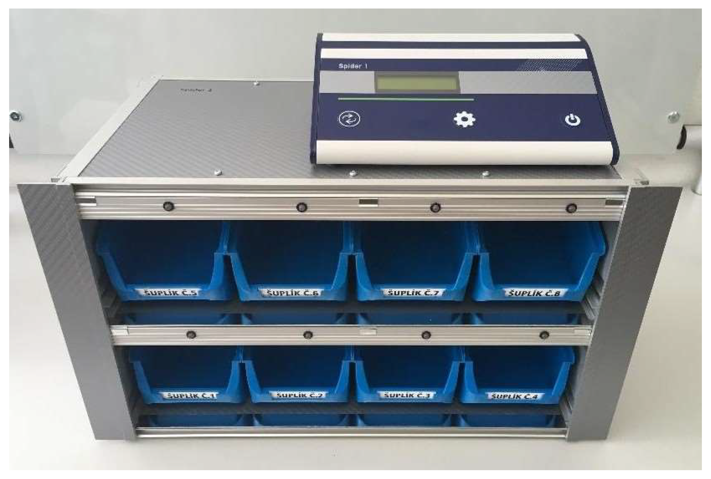
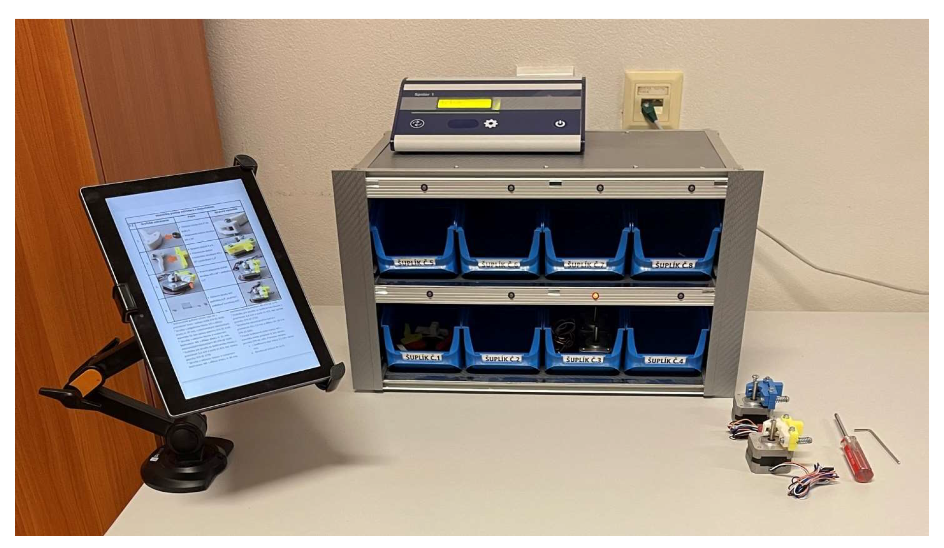
- Functional unit (Figure 4): The Spider 1 device consists of a rectangular aluminium structure divided by a 2 mm thick aluminium plate. Aluminium sheets protect its sides, covered with a self-adhesive carbon 3D film for durability. Plastic containers with dimensions of 75 × 102 × 160 mm are placed inside, designed with a 45° raised rear for easy component insertion and removal. Sensors and LEDs are positioned above these containers in aluminium rails.
- Portability: Spider 1 is a lightweight, compact, and portable device designed to meet customer needs.
- Additional components: The device includes two connecting cables made by modifying SCART-SCART cables with D-SUB MALE connectors. The wires are differentiated by the colour of their covers (grey and black). The power supply for the PTL device is AC/DC with a 10 W model, supporting input voltages of 100–240 V at 50–60 Hz and providing an output of 5 V/2 A through a 5.5/2.1 mm connector.
- Firstly, it involves the meticulous definition of implementation objectives and scope, addressing specific error types and identifying areas of application. Subsequently, a rigorous analysis of existing processes is conducted, incorporating worker observations, historical error-data review, and comprehensive process flow analysis.
- Selecting an appropriate Pick-to-Light system is pivotal, necessitating thorough research considering product types, facility layouts, and budgetary considerations. The design phase involves collaboration with system providers to tailor the plan, focusing on light placement, display configurations, and seamless integration with existing infrastructure.
- Installation and setup proceed as per design specifications, ensuring flawless functioning of components like lights, displays, and sensors. Employee training is paramount, enabling them to effectively utilize the system by understanding its operation, information interpretation, and response mechanisms [37].
- The system undergoes rigorous testing with various products and scenarios to unveil potential issues, followed by calibration for pinpoint accuracy. An integrated monitoring and feedback mechanism is established, continually tracking performance and fostering employee feedback for necessary adjustments.
- Continuous improvement, grounded in data analysis, drives enhancements and system updates. Documentation and standardization provide clear guidelines for system use, ensuring employee adherence. Maintenance and support frameworks are instituted, guaranteeing system integrity and addressing technical issues promptly.
- Regular evaluations assess the system’s effectiveness and ROI calculation quantifies financial benefits. Finally, successful initial implementations may prompt system expansion into other critical areas. This comprehensive procedure effectively minimises errors and defects by integrating Poka Yoke with Pick-to-Light technology, significantly enhancing manufacturing or picking process efficiency and product [38].
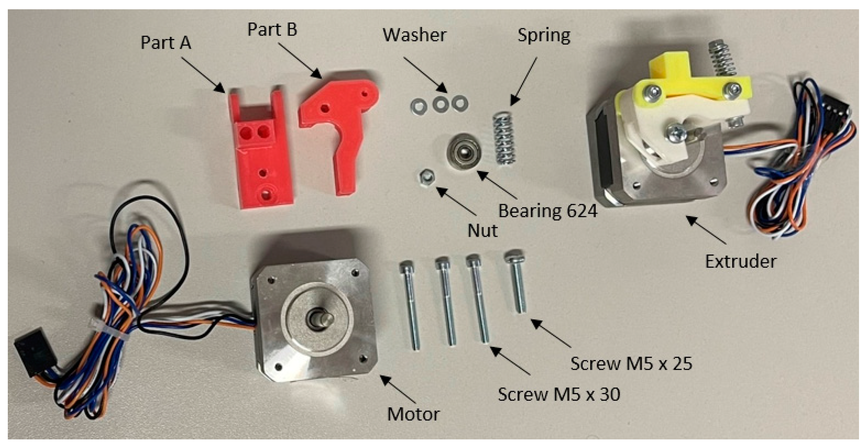
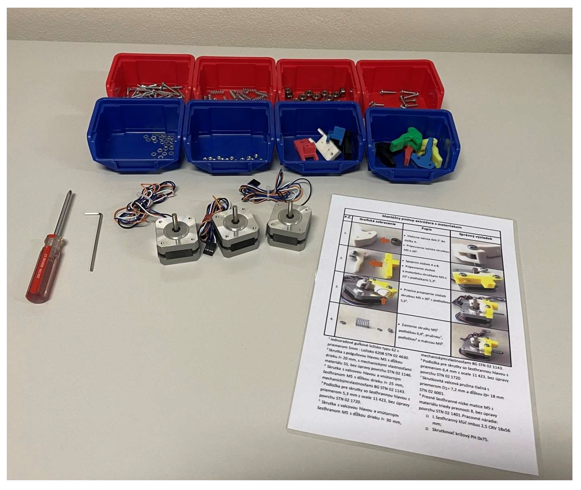
3.3. Model Component
4. Results
4.1. Test before Application of PTL
- -
- The length of the assembly-procedure training unnecessarily extends the start of the assembly process;
- -
- Frequent viewing of the assembly procedure—another unnecessary waste of time;
- -
- The constant pressure exerted by the moderator causes inattention and tension, resulting in errors and inappropriate pieces;
- -
- The simulation of such a situation arouses unnecessary nervousness and uncertainty in the student;
- -
- The workplace becomes uncomfortable and less and less psychologically bearable.
4.2. Test with PTL Application
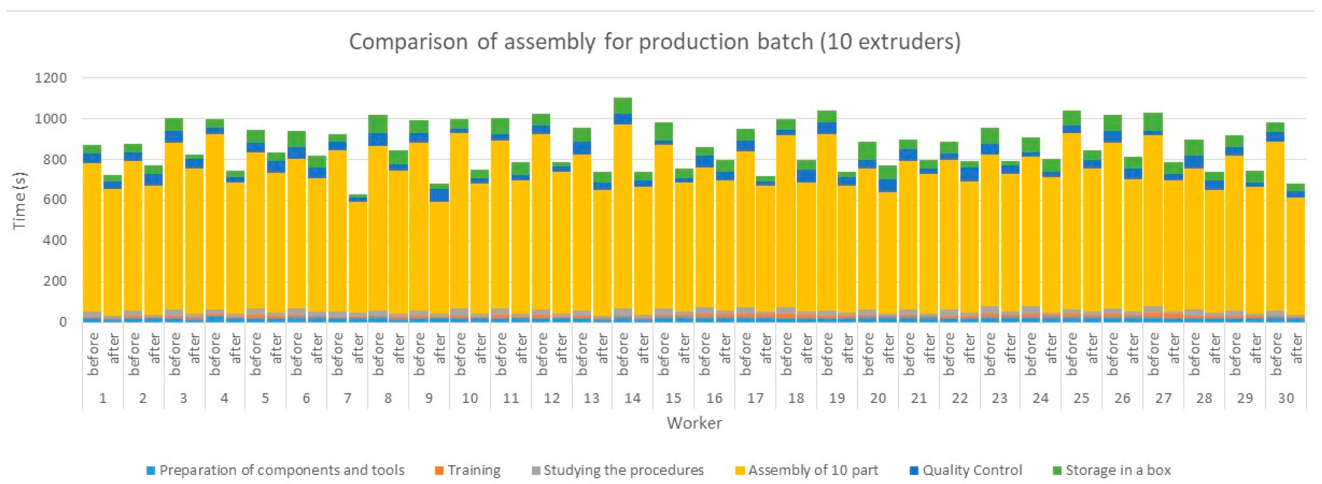
4.3. Evaluation of the Pick-to-Light System Introduction
5. Conclusions
- Improved work safety: The PTL system can benefit older employees or employees with health limitations who might be prone to injuries when manually picking components.
- Simplified training process: The PTL system may be easier for some user groups to control and master, which may mean less training time and improved productivity.
- Increased accuracy: The PTL system can benefit employees with limited ability to concentrate, leading to improved accuracy and reduced errors.
- High implementation costs: The PTL system can be expensive to implement and may require training of employees to use it, which may be difficult for some user groups.
- The need for a technological background: the PTL system requires using technologies such as sensors, light indicators and computer systems, which may not be suitable for some operations or user groups.
- Potential exclusion of certain groups: The PTL system may exclude employees with limited technology access or who are visually or hearing impaired, which may discriminate against these groups.
Author Contributions
Funding
Institutional Review Board Statement
Informed Consent Statement
Data Availability Statement
Acknowledgments
Conflicts of Interest
References
- Tsou, J.-C.; Chen, J.-M. Dynamic model for a defective production system with Poka-Yoke. J. Oper. Res. Soc. 2005, 56, 799–803. [Google Scholar] [CrossRef]
- Widjajanto, S.; Purba, H.H.; Jaqin, C. Novel POKA-YOKE approaching toward Industry-4.0: A literature review. Oper. Res. Eng. Sci. Theory Appl. 2020, 3, 65–83. [Google Scholar] [CrossRef]
- Martinelli, M.; Lippi, M.; Gamberini, R. Poka Yoke Meets Deep Learning: A Proof of Concept for an Assembly Line Application. Appl. Sci. 2022, 12, 11071. [Google Scholar] [CrossRef]
- Mandičák, T.; Mesároš, P.; Tkáč, M. Impact of management decisions based on managerial competencies and skills developed through BIM technology on performance of construction enterprises. Pollack Period. 2018, 13, 131–140. [Google Scholar] [CrossRef]
- Trebuna, P.; Pekarcikova, M.; Dic, M. Comparing Modern Manufacturing Tools and Their Effect on Zero-Defect Manufacturing Strategies. Appl. Sci. 2022, 12, 11487. [Google Scholar] [CrossRef]
- Baechler, A.; Baechler, L.; Autenrieth, S.; Kurtz, P.; Hoerz, T.; Heidenreich, T.; Kruell, G. A Comparative Study of an Assistance System for Manual Order Picking—Called Pick-by-Projection—With the Guiding Systems Pick-by-Paper, Pick-by-Light and Pick-by-Display. In Proceedings of the 49th Hawaii International Conference on System Sciences (HICSS), Koloa, HI, USA, 5–8 January 2016; pp. 523–531. [Google Scholar]
- Powell, D.J.; Romero, D. Digital Lean Manufacturing: A Literature Review. In Proceedings of the 2021 IEEE International Conference on Industrial Engineering and Engineering Management (IEEM), Singapore, 13–16 December 2021; pp. 659–662. [Google Scholar]
- Dudek-Burlikowska, M.; Szewieczek, D. The Poka-Yoke method as an improving quality tool of operations in the process. J. Achiev. Mater. Manuf. Eng. 2009, 36, 95–102. [Google Scholar]
- Belu, N.; Ionescu, L.M.; Misztal, A.; Mazăre, A. Poka Yoke system based on image analysis and object recognition. Mod. Technol. Ind. Eng. 2015, 95, 012138. [Google Scholar] [CrossRef]
- Pankaj, S.; Tarun, Y. Review Paper on “Productivity Improvement by using Poka-Yoke”. Int. Res. J. Eng. Technol. 2018, 5, 761–763. [Google Scholar]
- Vinayagasundaram, R.; Velmurugan, C. Implementation of Zero Defect through POKA YOKE Approaches in the Assembly Line of Compressor Manufacturing Industry. Int. J. Pure Appl. Math. 2018, 119, 2319–2332. [Google Scholar]
- Zhang, A. Quality improvement through Poka-Yoke: From engineering design to information system design. Int. J. Six Sigma Compet. Advant. 2014, 8, 147–159. [Google Scholar] [CrossRef]
- Alogla, A.A.; Alruqi, M. Aircraft Assembly Snags: Human Errors or Lack of Production Design? Aerospace 2021, 8, 391. [Google Scholar] [CrossRef]
- Sodhi, R.; Benko, H.; Wilson, A. LightGuide: Projected visualizations for hand movement guidance. In Proceedings of the SIGCHI Conference on Human Factors in Computing Systems (CHI ’12), Austin, TX, USA, 5–10 May 2012; Association for Computing Machinery: New York, NY, USA, 2012; pp. 179–188. [Google Scholar]
- Yang, C.; Xu, S.; Yu, T.; Liu, G.; Yu, C.; Shi, Y. LightGuide: Directing Visually Impaired People along a Path Using Light Cues. In Proceedings of the ACM on Interactive, Mobile, Wearable and Ubiquitous Technologies; Association for Computing Machinery: New York, NY, USA, 2021; Volume 5, p. 84. [Google Scholar] [CrossRef]
- Chung, J.; Kim, I.-J.; Schmandt, C. Guiding Light: Navigation assistance system using projection based augmented reality. In Proceedings of the IEEE International Conference on Consumer Electronics (ICCE), Las Vegas, NV, USA, 9–12 January 2011; pp. 881–882. [Google Scholar]
- Tosin, T. Perancangan dan Implementasi Komunikasi RS-485 Menggunakan Protokol Modbus RTU dan Modbus TCP Pada Sistem Pick-By-Light. Komputika J. Sist. Komput. 2021, 10, 85–91. [Google Scholar] [CrossRef]
- Sitthikarn, P.; Hakimi, P. Pick to Light Systems; Faculty of Engineering, Thammasat University: Bangkok, Thailand, 2016. [Google Scholar]
- Daneshjo, N.; Mares, A.; Pajerska, E.D.; Hajduova, Z. Designing and Upgrading the Assembly Process and Verifying the Performance of the Pick to Light System Program. Adv. Sci. Technol. Res. J. 2018, 12, 126–135. [Google Scholar] [CrossRef] [PubMed]
- Blecharz, P. Basics of Modern Quality Management; Ekopress: Praha, Czech Republic, 2011; p. 122. [Google Scholar]
- Hirano, H.; Shibun, N.K. POKA-YOKE Improving Product Quality by Preventing Defects; Productivity Press: New York, NY, USA, 1988; p. 275. [Google Scholar]
- Martisovic, R. Poka Yoke. Available online: http://www.produktivne.sk/vsetko-o-lean/metody/poka-yoke/ (accessed on 4 April 2023).
- Saleh, J.I. The Role of Empovering Leadership in Enhancing the Adaptive Penformance of Employees. Acta Technol. 2022, 8, 1–6. [Google Scholar] [CrossRef]
- Saderova, J.; Rosova, A.; Behunova, A.; Behun, M.; Sofranko, M.; Khouri, S. Case study: The simulation modelling of selected activity in a warehouse operation. Wirel. Netw. 2022, 28, 431–440. [Google Scholar] [CrossRef]
- Mildorf, L. Poka-Yoke: Prevention of Discrepancies in the Production Process. Available online: http://katedry.fmmi.vsb.cz/639/qmag/mj41-cz.pdf (accessed on 5 April 2023).
- Straka, M. Design of a Computer-Aided Location Expert System Based on a Mathematical Approach. Mathematics 2021, 9, 1052. [Google Scholar] [CrossRef]
- Andriolo, A.; Battini, D.; Calzavara, M.; Gamberi, M.; Peretti, U.; Persona, A.; Pilati, F.; Sgarbossa, F. New RFID pick-to-light system: Operating characteristics and future potential. Int. J. RF Technol. Res. Appl. 2016, 7, 43–63. [Google Scholar] [CrossRef]
- Pick to Light Systems. Available online: http://www.marpex.sk/riesenia-a-technologie/pick-to-light/ (accessed on 5 April 2023).
- Hrehova, S.; Vagaska, A. Computer Models as Appropriate Tools in Elearning. In Proceedings of the INTED2017: 11th International Technology, Education and Development Conference, Valencia, Spain, 6–8 March 2017; pp. 8871–8877. [Google Scholar]
- Richnák, P.; Fidlerová, H. Impact and Potential of Sustainable Development Goals in Dimension of the Technological Revolution Industry 4.0 within the Analysis of Industrial Enterprises. Energies 2022, 15, 3697. [Google Scholar] [CrossRef]
- Dąbrowska, M.; Medyński, D.; Bieliński, W.; Kolbusz, K. Reorganization of the assembly station in the production process of the sliding floor for reloading ramps in the context of improving the quality of the finished product. Technol. I Autom. Montażu (Assem. Tech. Technol.) 2022, 117, 28–35. [Google Scholar] [CrossRef]
- Kochańska, J.; Burduk, A.; Markowski, M.; Kłusek, A.; Wojciechowska, M. Improvement of Factory Transport Efficiency with Use of WiFi-Based Technique for Monitoring Industrial Vehicles. Sustainability 2023, 15, 1113. [Google Scholar] [CrossRef]
- Pačaiová, H.; Korba, P.; Hovanec, M.; Galanda, J.; Šváb, P.; Lukáč, J. Use of Simulation Tools for Optimization of the Time Duration of Winter Maintenance Activities at Airports. Sustainability 2021, 13, 1095. [Google Scholar] [CrossRef]
- Kolbusz, P. The use of the six sigma methodology in a project improving the manufacturing process. Technol. I Autom. Montażu 2022, 118, 8–19. [Google Scholar] [CrossRef]
- Kaľavský, P.; Rozenberg, R.; Korba, P.; Kelemen, M., Jr.; Antoško, M.; Sabo, J.; Džunda, M. Research of the Photo-Optical Method Application for Measuring Selected Data on the Movement of a Parachute for Type M-282. Appl. Sci. 2021, 11, 5637. [Google Scholar] [CrossRef]
- Medyński, D.; Bonarski, P.; Motyka, P.; Wysoczański, A.; Gnitecka, R.; Kolbusz, K.; Dąbrowska, M.; Burduk, A.; Pawelec, Z.; Machado, J. Digital Standardization of Lean Manufacturing Tools According to Industry 4.0 Concept. Appl. Sci. 2023, 13, 6259. [Google Scholar] [CrossRef]
- Lishchenko, N.; Piteľ, J.; Larshin, V. Online Monitoring of Surface Quality for Diagnostic Features in 3D Printing. Machines 2022, 10, 541. [Google Scholar] [CrossRef]
- Stockinger, C.; Steinebach, T.; Petrat, D.; Bruns, R.; Zöller, I. The Effect of Pick-by-Light-Systems on Situation Awareness in Order Picking Activities. Procedia Manuf. 2020, 45, 96–101. [Google Scholar] [CrossRef]
- Kaščak, J.; Gašpár, Š.; Paško, J.; Knapčíková, L.; Husár, J.; Baron, P.; Török, J. Design of an Atypical Construction of Equipment for Additive Manufacturing with a Conceptual Solution of a Printhead Intended for the Use of Recycled Plastic Materials. Appl. Sci. 2021, 11, 2928. [Google Scholar] [CrossRef]
- Mascenik, J.; Coranic, T. Experimental Determination of the Coefficient of Friction on a Screw Joint. Appl. Sci. 2022, 12, 11987. [Google Scholar] [CrossRef]


| Sex | % | Year | % | Education | % | Work Assignment | % |
|---|---|---|---|---|---|---|---|
| Male | 14 | 21–30 years | 14 | Basic | 2 | Assembly worker | 12 |
| Female | 16 | 31–40 years | 11 | Secondary vocational | 16 | Production worker | 11 |
| 41–50 years | 3 | High school diploma | 4 | Service personnel | 3 | ||
| 51–60 years | 2 | University education | 8 | An engineer | 4 |
| Operation/Worker (s) | 1 | 2 | 3 | 4 | 5 | 6 | 7 | 8 | … | 30 | Average Time (s) |
|---|---|---|---|---|---|---|---|---|---|---|---|
| Component and tool preparation | 20 | 22 | 21 | 30 | 22 | 25 | 24 | 26 | … | 26 | 24.7 |
| Training | 5 | 10 | 12 | 10 | 13 | 11 | 5 | 6 | … | 7 | 11.16667 |
| Studying the procedure | 30 | 27 | 29 | 25 | 35 | 32 | 26 | 24 | … | 26 | 29.66667 |
| Assembly of one part | 65 | 65 | 69 | 62 | 63 | 65 | 68 | 70 | … | 61 | 63.83333 |
| Assembly of the production batch (10 pcs.) | 726 | 736 | 820 | 862 | 763 | 734 | 792 | 812 | … | 826 | 789.7667 |
| Connection check | 5 | 4 | 6 | 3 | 5 | 6 | 4 | 6 | … | 5 | 4.433333 |
| Storage in a box | 4 | 4 | 6 | 4 | 6 | 8 | 4 | 9 | … | 5 | 6.433333 |
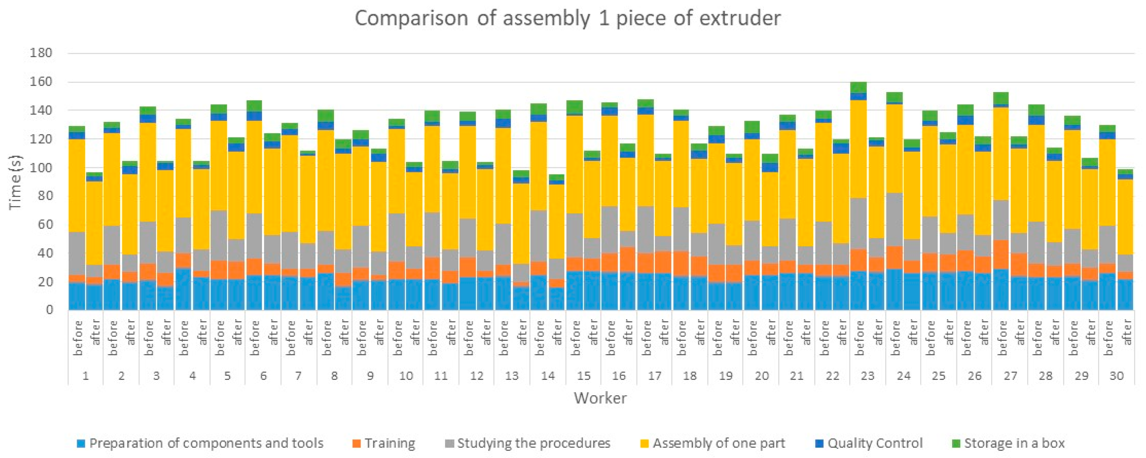
| Total assembly time 1pc. | 129 | 132 | 143 | 134 | 144 | 147 | 131 | 141 | … | 130 | 140.2333 |
| Total assembly time 10 pcs. | 871 | 875 | 1002 | 997 | 943 | 942 | 927 | 1018 | … | 985 | 963.9667 |
| Operation/Worker (s) | 1 | 2 | 3 | 4 | 5 | 6 | 7 | 8 | … | 30 | Average Time (s) |
|---|---|---|---|---|---|---|---|---|---|---|---|
| Component and tool preparation | 18 | 20 | 17 | 23 | 22 | 25 | 23 | 17 | … | 22 | 22.633 |
| Training | 5 | 7 | 9 | 5 | 12 | 8 | 6 | 9 | … | 5 | 8.8 |
| Studying the procedure | 9 | 12 | 15 | 15 | 16 | 20 | 18 | 17 | … | 12 | 14.433 |
| Assembly of one part | 58 | 56 | 57 | 56 | 61 | 60 | 61 | 67 | … | 53 | 57.4 |
| Assembly of the production batch (10 pcs.) | 621 | 632 | 712 | 642 | 684 | 657 | 544 | 702 | … | 573 | 639.6 |
| Connection check | 4 | 6 | 5 | 3 | 6 | 5 | 2 | 3 | … | 3 | 3.966 |
| Storage in a box | 3 | 4 | 2 | 3 | 4 | 6 | 2 | 7 | … | 4 | 4.333 |
| Total assembly time 1pc. | 97 | 105 | 105 | 105 | 121 | 124 | 112 | 120 | … | 99 | 111.566 |
| Total assembly time 10 pcs. | 723 | 771 | 823 | 745 | 834 | 820 | 631 | 845 | … | 682 | 768.466 |
| Assembly/Worker | 1 | 2 | 3 | 4 | 5 | 6 | 7 | 8 | 9 | 10 | 11 | 12 | 13 | 14 | 15 | 16 | 17 | 18 | 19 | 20 | 21 | 22 | 23 | 24 | 25 | 26 | 27 | 28 | 29 | 30 |
|---|---|---|---|---|---|---|---|---|---|---|---|---|---|---|---|---|---|---|---|---|---|---|---|---|---|---|---|---|---|---|
| 1 | x | x | x | |||||||||||||||||||||||||||
| 2 | x | x | x | x | x | x | x | x | ||||||||||||||||||||||
| 3 | x | x | ||||||||||||||||||||||||||||
| 4 | x | x | x | x | x | |||||||||||||||||||||||||
| 5 | x | |||||||||||||||||||||||||||||
| 6 | x | x | x | x | x | |||||||||||||||||||||||||
| 7 | x | x | x | x | ||||||||||||||||||||||||||
| 8 | x | x | x | |||||||||||||||||||||||||||
| 9 | x | x | x | |||||||||||||||||||||||||||
| 10 |
| Assembly/Worker | 1 | 2 | 3 | 4 | 5 | 6 | 7 | 8 | 9 | 10 | 11 | 12 | 13 | 14 | 15 | 16 | 17 | 18 | 19 | 20 | 21 | 22 | 23 | 24 | 25 | 26 | 27 | 28 | 29 | 30 |
|---|---|---|---|---|---|---|---|---|---|---|---|---|---|---|---|---|---|---|---|---|---|---|---|---|---|---|---|---|---|---|
| 1 | x | x | x | |||||||||||||||||||||||||||
| 2 | x | x | x | x | x | x | x | |||||||||||||||||||||||
| 3 | x | |||||||||||||||||||||||||||||
| 4 | x | x | x | x | x | x | ||||||||||||||||||||||||
| 5 | ||||||||||||||||||||||||||||||
| 6 | x | x | ||||||||||||||||||||||||||||
| 7 | x | |||||||||||||||||||||||||||||
| 8 | x | x | ||||||||||||||||||||||||||||
| 9 | ||||||||||||||||||||||||||||||
| 10 |
Disclaimer/Publisher’s Note: The statements, opinions and data contained in all publications are solely those of the individual author(s) and contributor(s) and not of MDPI and/or the editor(s). MDPI and/or the editor(s) disclaim responsibility for any injury to people or property resulting from any ideas, methods, instructions or products referred to in the content. |
© 2023 by the authors. Licensee MDPI, Basel, Switzerland. This article is an open access article distributed under the terms and conditions of the Creative Commons Attribution (CC BY) license (https://creativecommons.org/licenses/by/4.0/).
Share and Cite
Trojanowska, J.; Husár, J.; Hrehova, S.; Knapčíková, L. Poka Yoke in Smart Production Systems with Pick-to-Light Implementation to Increase Efficiency. Appl. Sci. 2023, 13, 11715. https://doi.org/10.3390/app132111715
Trojanowska J, Husár J, Hrehova S, Knapčíková L. Poka Yoke in Smart Production Systems with Pick-to-Light Implementation to Increase Efficiency. Applied Sciences. 2023; 13(21):11715. https://doi.org/10.3390/app132111715
Chicago/Turabian StyleTrojanowska, Justyna, Jozef Husár, Stella Hrehova, and Lucia Knapčíková. 2023. "Poka Yoke in Smart Production Systems with Pick-to-Light Implementation to Increase Efficiency" Applied Sciences 13, no. 21: 11715. https://doi.org/10.3390/app132111715