
3D Point Cloud Completion Method Based on Building Contour Constraint Diffusion Probability Model
 , and
, and
Abstract
:1. Introduction
2. Related Works
2.1. Traditional Point Cloud Completion Methods
2.2. Deep Learning-Based Point Cloud Completion Methods
2.2.1. Voxel-Based Method
2.2.2. Transformer-Based Methods
2.2.3. Point-Based Method
3. Methods
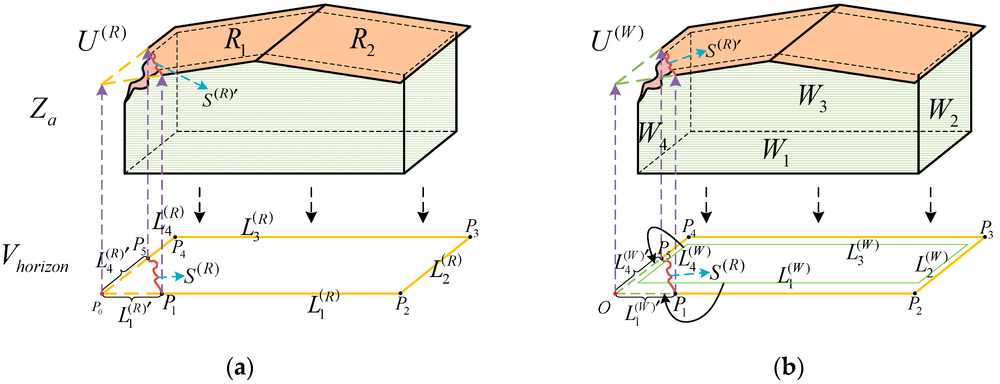
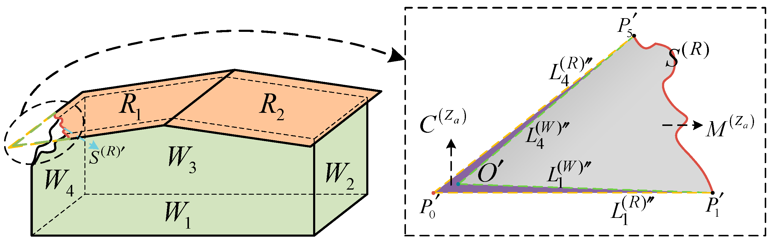
3.1. Contour Constraint
3.1.1. Grouping of Building Surface Polygons
3.1.2. Definition of Building Surface Polygon Attributes
3.1.3. Constructing Contour Constraint Polygons
3.1.4. Constructing Contour Constraint Regions
3.2. Diffusion
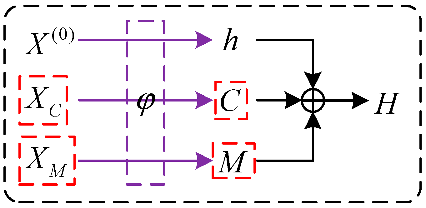
3.3. Point Encoding
3.4. Reverse
3.5. Training Objectives
4. Experimental Section
4.1. Experimental Dataset and Processing
4.2. Experimental Equipment and Model Training Configuration
4.3. Evaluation Metrics
4.4. Comparative Analysis of Experimental Results
4.5. Completion Comparison Experiments under Different Missing Rates
4.6. Ablation Experiment
5. Discussion
6. Conclusions
- (1)
- By grouping building surface polygons, we simplified the process of constructing building-contour-constrained polygons. This eliminates the need for training complex point cloud semantic segmentation models to obtain the required building-contour-constrained regions.
- (2)
- In the comparison experiments presented in Table 1 and Table 2, our method demonstrates superior building point cloud completion accuracy compared to other point cloud completion methods, such as PCN, PF-Net, and VRC-Net. This is because we incorporated the geometric contour information of the target building point cloud during the building point cloud completion process, resulting in a point cloud distribution that closely matches the geometric shape of the target building.
Author Contributions
Funding
Institutional Review Board Statement
Informed Consent Statement
Data Availability Statement
Conflicts of Interest
References
- Yang, B.; Haala, N.; Dong, Z. Progress and perspectives of point cloud intelligence. Geo-Spat. Inf. Sci. 2023, 26, 189–205. [Google Scholar] [CrossRef]
- Yu, B.; Liu, H.; Wu, J.; Hu, Y.; Zhang, L. Automated derivation of urban building density information using airborne LiDAR data and object-based method. Landsc. Urban Plan. 2010, 98, 210–219. [Google Scholar] [CrossRef]
- Wang, R.; Huang, S.; Yang, H. Building3D: An Urban-Scale Dataset and Benchmarks for Learning Roof Structures from Point Clouds. arXiv 2023. [Google Scholar] [CrossRef]
- Guo, Y.; Wang, H.; Hu, Q.; Liu, H.; Liu, L.; Bennamoun, M. Deep learning for 3d point clouds: A survey. IEEE Trans. Pattern Anal. Mach. Intell. 2020, 43, 4338–4364. [Google Scholar] [CrossRef]
- Berger, M.; Tagliasacchi, A.; Seversky, L.M.; Alliez, P.; Levine, J.A.; Sharf, A.; Silva, C.T. State of the art in surface reconstruction from point clouds. In Proceedings of the 35th Annual Conference of the European Association for Computer Graphics, Eurographics 2014-State of the Art Reports, Strasbourg, France, 7–11 April 2014; pp. 161–185. [Google Scholar] [CrossRef]
- Goodfellow, I.; Pouget-Abadie, J.; Mirza, M.; Xu, B.; Warde-Farley, D.; Ozair, S.; Courville, A.; Bengio, Y. Generative adversarial networks. Commun. ACM 2020, 63, 139–144. [Google Scholar] [CrossRef]
- Kingma, D.P.; Welling, M. Auto-encoding variational bayes. arXiv 2013. [Google Scholar] [CrossRef]
- Kobyzev, I.; Prince, S.J.; Brubaker, M.A. Normalizing flows: An introduction and review of current methods. IEEE Trans. Pattern Anal. Mach. Intell. 2020, 43, 3964–3979. [Google Scholar] [CrossRef]
- Ho, J.; Jain, A.; Abbeel, P. Denoising diffusion probabilistic models. Adv. Neural Inf. Process. Syst. 2020, 33, 6840–6851. [Google Scholar] [CrossRef]
- Cheng, M.; Li, G.; Chen, Y.; Chen, J.; Wang, C.; Li, J. Dense point cloud completion based on generative adversarial network. IEEE Trans. Geosci. Remote. Sens. 2021, 60, 1–10. [Google Scholar] [CrossRef]
- Li, C.-L.; Zaheer, M.; Zhang, Y.; Poczos, B.; Salakhutdinov, R. Point cloud gan. arXiv 2018. [Google Scholar] [CrossRef]
- Spurek, P.; Kasymov, A.; Mazur, M.; Janik, D.; Tadeja, S.K.; Tabor, J.; Trzciński, T. Hyperpocket: Generative point cloud completion. In Proceedings of the 2022 IEEE/RSJ International Conference on Intelligent Robots and Systems (IROS), Kyoto, Japan, 23–27 October 2022; pp. 6848–6853. [Google Scholar] [CrossRef]
- Yang, G.; Huang, X.; Hao, Z.; Liu, M.-Y.; Belongie, S.; Hariharan, B. Pointflow: 3d point cloud generation with continuous normalizing flows. In Proceedings of the IEEE/CVF International Conference on Computer Vision, Seoul, Republic of Korea, 27 October–2 November 2019; pp. 4541–4550. [Google Scholar] [CrossRef]
- Luo, S.; Hu, W. Diffusion Probabilistic Models for 3D Point Cloud Generation. In Proceedings of the 2021 IEEE/CVF Conference on Computer Vision and Pattern Recognition (CVPR), Nashville, TN, USA, 20–25 June 2021; pp. 2836–2844. [Google Scholar] [CrossRef]
- Gallo, O.; Manduchi, R.; Rafii, A. CC-RANSAC: Fitting planes in the presence of multiple surfaces in range data. Pattern Recognit. Lett. 2011, 32, 403–410. [Google Scholar] [CrossRef]
- Yuan, W.; Khot, T.; Held, D.; Mertz, C.; Hebert, M. PCN: Point Completion Network. In Proceedings of the 2018 International Conference on 3D Vision (3DV), Verona, Italy, 5–8 September 2018; pp. 728–737. [Google Scholar] [CrossRef]
- Thrun, S.; Wegbreit, B. Shape from symmetry. In Proceedings of the Tenth IEEE International Conference on Computer Vision (ICCV’05) Volume 1, Beijing, China, 17–21 October 2005; pp. 1824–1831. [Google Scholar] [CrossRef]
- Li, Z.; Shan, J. RANSAC-based multi primitive building reconstruction from 3D point clouds. ISPRS J. Photogramm. Remote Sens. 2022, 185, 247–260. [Google Scholar] [CrossRef]
- Verdie, Y.; Lafarge, F.; Alliez, P. LOD generation for urban scenes. ACM Trans. Graph. 2015, 34, 30. [Google Scholar] [CrossRef]
- Wu, Z.; Song, S.; Khosla, A.; Yu, F.; Zhang, L.; Tang, X.; Xiao, J. 3d shapenets: A deep representation for volumetric shapes. In Proceedings of the IEEE Conference on Computer Vision and Pattern Recognition, Boston, MA, USA, 7–12 June 2015; pp. 1912–1920. [Google Scholar] [CrossRef]
- Nguyen, D.T.; Hua, B.-S.; Tran, K.; Pham, Q.-H.; Yeung, S.-K. A field model for repairing 3d shapes. In Proceedings of the IEEE Conference on Computer Vision and Pattern Recognition, Las Vegas, NV, USA, 27–30 June 2016; pp. 5676–5684. [Google Scholar] [CrossRef]
- Han, X.; Li, Z.; Huang, H.; Kalogerakis, E.; Yu, Y. High-resolution shape completion using deep neural networks for global structure and local geometry inference. In Proceedings of the IEEE International Conference on Computer Vision, Venice, Italy, 22 September 2017; pp. 85–93. [Google Scholar] [CrossRef]
- Dai, A.; Ruizhongtai Qi, C.; Nießner, M. Shape completion using 3d-encoder-predictor cnns and shape synthesis. In Proceedings of the IEEE Conference on Computer Vision and Pattern Recognition, Honolulu, HI, USA, 21–26 July 2017; pp. 5868–5877. [Google Scholar] [CrossRef]
- Xie, H.; Yao, H.; Zhou, S.; Mao, J.; Zhang, S.; Sun, W. Grnet: Gridding residual network for dense point cloud completion. In Proceedings of the European Conference on Computer Vision, Glasgow, UK, 23–28 August 2020; pp. 365–381. [Google Scholar] [CrossRef]
- Liu, X.; Liu, X.; Liu, Y.S.; Han, Z. SPU-Net: Self-Supervised Point Cloud Upsampling by Coarse-to-Fine Reconstruction with Self-Projection Optimization. IEEE Trans. Image Process. 2022, 31, 4213–4226. [Google Scholar] [CrossRef] [PubMed]
- Yu, X.; Rao, Y.; Wang, Z.; Liu, Z.; Lu, J.; Zhou, J. Pointr: Diverse Point Cloud Completion with Geometry-Aware Transformers. In Proceedings of the IEEE/CVF International Conference on Computer Vision, Montreal, QC, Canada, 10–17 October 2021; pp. 12498–12507. [Google Scholar] [CrossRef]
- Wen, X.; Xiang, P.; Han, Z.; Cao, Y.-P.; Wan, P.; Zheng, W.; Liu, Y.-S. PMP-Net++: Point cloud completion by transformer-enhanced multi-step point moving paths. IEEE Trans. Pattern Anal. Mach. Intell. 2022, 45, 852–867. [Google Scholar] [CrossRef] [PubMed]
- Wen, X.; Xiang, P.; Han, Z.; Cao, Y.-P.; Wan, P.; Zheng, W.; Liu, Y.-S. Pmp-net: Point cloud completion by learning multi-step point moving paths. In Proceedings of the IEEE/CVF Conference on Computer Vision and Pattern Recognition, Nashville, TN, USA, 20–25 June 2021; pp. 7443–7452. [Google Scholar] [CrossRef]
- Qi, C.R.; Su, H.; Mo, K.; Guibas, L.J. Pointnet: Deep learning on point sets for 3d classification and segmentation. In Proceedings of the IEEE Conference on Computer Vision and Pattern Recognition, Honolulu, HI, USA, 21–26 July 2017; pp. 652–660. [Google Scholar] [CrossRef]
- Qi, C.R.; Yi, L.; Su, H.; Guibas, L.J. Pointnet++: Deep hierarchical feature learning on point sets in a metric space. Adv. Neural Inf. Process. Syst. 2017, 30. [Google Scholar] [CrossRef]
- Groueix, T.; Fisher, M.; Kim, V.G.; Russell, B.C.; Aubry, M. A papier-mâché approach to learning 3d surface generation. In Proceedings of the IEEE Conference on Computer Vision and Pattern Recognition, Salt Lake City, UT, USA, 18–23 June 2018; pp. 216–224. [Google Scholar] [CrossRef]
- Chang, Y.; Jung, C.; Xu, Y. FinerPCN: High fidelity point cloud completion network using pointwise convolution. Neurocomputing 2021, 460, 266–276. [Google Scholar] [CrossRef]
- Tang, J.; Gong, Z.; Yi, R.; Xie, Y.; Ma, L. Lake-net: Topology-aware point cloud completion by localizing aligned keypoints. In Proceedings of the IEEE/CVF Conference on Computer Vision and Pattern Recognition, New Orleans, LA, USA, 18–24 June 2022; pp. 1726–1735. [Google Scholar] [CrossRef]
- Wei, M.; Wei, Z.; Zhou, H.; Hu, F.; Si, H.; Chen, Z.; Zhu, Z.; Qiu, J.; Yan, X.; Guo, Y.; et al. AGConv: Adaptive Graph Convolution on 3D Point Clouds. IEEE Trans. Pattern Anal. Mach. Intell. 2023, 45, 9374–9392. [Google Scholar] [CrossRef]
- Wen, X.; Han, Z.; Cao, Y.-P.; Wan, P.; Zheng, W.; Liu, Y.-S. Cycle4completion: Unpaired point cloud completion using cycle transformation with missing region coding. In Proceedings of the IEEE/CVF Conference on Computer Vision and Pattern Recognition, Nashville, TN, USA, 20–25 June 2021; pp. 13080–13089. [Google Scholar] [CrossRef]
- Zhang, J.; Chen, X.; Cai, Z.; Pan, L.; Zhao, H.; Yi, S.; Yeo, C.K.; Dai, B.; Loy, C.C. Unsupervised 3D Shape Completion through GAN Inversion. In Proceedings of the 2021 IEEE/CVF Conference on Computer Vision and Pattern Recognition (CVPR), Nashville, TN, USA, 20–25 June 2021; pp. 1768–1777. [Google Scholar] [CrossRef]
- Huang, Z.; Yu, Y.; Xu, J.; Ni, F.; Le, X. PF-Net: Point Fractal Network for 3D Point Cloud Completion. In Proceedings of the 2020 IEEE/CVF Conference on Computer Vision and Pattern Recognition (CVPR), Seattle, WA, USA, 13–19 June 2020; pp. 7659–7667. [Google Scholar] [CrossRef]
- Xu, M.; Wang, Y.; Liu, Y.; He, T.; Qiao, Y. CP3: Unifying Point Cloud Completion by Pretrain-Prompt-Predict Paradigm. IEEE Trans. Pattern Anal. Mach. Intell. 2023, 45, 9583–9594. [Google Scholar] [CrossRef]
- Pan, L.; Chen, X.; Cai, Z.; Zhang, J.; Zhao, H.; Yi, S.; Liu, Z. Variational relational point completion network. In Proceedings of the IEEE/CVF Conference on Computer Vision and Pattern Recognition, Nashville, TN, USA, 20–25 June 2021; pp. 8524–8533. [Google Scholar] [CrossRef]
- Hu, P.; Miao, Y.; Hou, M. Reconstruction of complex roof semantic structures from 3d point clouds using local convexity and consistency. Remote Sens. 2021, 13, 1946. [Google Scholar] [CrossRef]
- Desolneux, A.; Moisan, L.; Morel, J.-M. Gestalt theory and computer vision. In Seeing, Thinking and Knowing: Meaning and Self-Organisation in Visual Cognition and Thought; Springer: Berlin/Heidelberg, Germany, 2004; pp. 71–101. [Google Scholar]
- GB 50007-2011; National Standard of the People’s Republic of China Code for Design of Building Foundation. National Standards of People’s Republic of China: Beijing, China, 2012.
- Selvaraju, P.; Nabail, M.; Loizou, M.; Maslioukova, M.; Averkiou, M.; Andreou, A.; Chaudhuri, S.; Kalogerakis, E. BuildingNet: Learning to label 3D buildings. In Proceedings of the IEEE/CVF International Conference on Computer Vision, Montreal, QC, Canada, 10–17 October 2021; pp. 10397–10407. [Google Scholar] [CrossRef]
- Kingma, D.P.; Ba, J. Adam: A method for stochastic optimization. arXiv 2014. [Google Scholar] [CrossRef]
- Fan, H.; Su, H.; Guibas, L.J. A point set generation network for 3d object reconstruction from a single image. In Proceedings of the IEEE Conference on Computer Vision and Pattern Recognition, Honolulu, HI, USA, 21–26 July 2017; pp. 605–613. [Google Scholar] [CrossRef]


| Building 1 | Building 2 | |||||||
|---|---|---|---|---|---|---|---|---|
| Model | dCD (↓) | dEMD (↓) | dCD (↓) | dEMD (↓) | ||||
| G→R | R→G | G→R | R→G | G→R | R→G | G→R | R→G | |
| PCN | 2.896 | 3.112 | 6.121 | 6.099 | 3.405 | 2.887 | 7.335 | 7.686 |
| PF-Net | 2.06 | 1.838 | 4.001 | 3.773 | 2.417 | 2.165 | 4.808 | 4.431 |
| VRC-Net | 1.419 | 1.307 | 3.853 | 3.531 | 1.774 | 1.579 | 4.434 | 4.182 |
| Ours | 1.057 | 0.828 | 3.568 | 3.196 | 1.646 | 1.522 | 4.253 | 4.015 |
| Building 1 | Building 2 | |||||||
|---|---|---|---|---|---|---|---|---|
| Model | dCD (↓) | dEMD (↓) | dCD (↓) | dEMD (↓) | ||||
| G→R | R→G | G→R | R→G | G→R | R→G | G→R | R→G | |
| PCN | 5.674 | 5.763 | 9.156 | 9.043 | 7.263 | 7.038 | 11.847 | 11.647 |
| PF-Net | 4.835 | 4.785 | 7.248 | 6.97 | 6.098 | 5.945 | 8.566 | 8.891 |
| VRC-Net | 4.248 | 4.196 | 6.863 | 6.725 | 5.059 | 4.903 | 7.695 | 7.633 |
| Ours | 3.831 | 3.781 | 6.324 | 6.428 | 4.817 | 4.512 | 7.314 | 7.062 |
| Missing Ratio | VRC-Net | Model [14] | Our | |||
|---|---|---|---|---|---|---|
| G→R | R→G | G→R | R→G | G→R | R→G | |
| 10% | 2.431 | 2.095 | 2.619 | 2.283 | 1.835 | 1.606 |
| 15% | 2.879 | 2.607 | 3.011 | 2.718 | 2.051 | 1.811 |
| 20% | 5.154 | 4.942 | 4.914 | 4.868 | 3.586 | 2.963 |
| 25% | 8.672 | 8.261 | 8.226 | 8.052 | 7.902 | 7.515 |
| Contour-Constrained Shape Latent Code | dCD (↓) | |||
|---|---|---|---|---|
| Type | G→R | R→G | ||
| Baseline Model | × | × | 1.711 | 1.508 |
| Model 1 | ✔ | × | 1.556 | 0.923 |
| Model 2 | × | ✔ | 1.231 | 1.126 |
| Our | ✔ | ✔ | 0.928 | 0.751 |
Disclaimer/Publisher’s Note: The statements, opinions and data contained in all publications are solely those of the individual author(s) and contributor(s) and not of MDPI and/or the editor(s). MDPI and/or the editor(s) disclaim responsibility for any injury to people or property resulting from any ideas, methods, instructions or products referred to in the content. |
© 2023 by the authors. Licensee MDPI, Basel, Switzerland. This article is an open access article distributed under the terms and conditions of the Creative Commons Attribution (CC BY) license (https://creativecommons.org/licenses/by/4.0/).
Share and Cite
Ye, B.; Wang, H.; Li, J.; Jiang, J.; Lu, Y.; Gao, E.; Yue, T. 3D Point Cloud Completion Method Based on Building Contour Constraint Diffusion Probability Model. Appl. Sci. 2023, 13, 11246. https://doi.org/10.3390/app132011246
Ye B, Wang H, Li J, Jiang J, Lu Y, Gao E, Yue T. 3D Point Cloud Completion Method Based on Building Contour Constraint Diffusion Probability Model. Applied Sciences. 2023; 13(20):11246. https://doi.org/10.3390/app132011246
Chicago/Turabian StyleYe, Bo, Han Wang, Jingwen Li, Jianwu Jiang, Yanling Lu, Ertao Gao, and Tao Yue. 2023. "3D Point Cloud Completion Method Based on Building Contour Constraint Diffusion Probability Model" Applied Sciences 13, no. 20: 11246. https://doi.org/10.3390/app132011246