Article

Parametric Analysis for Hybrid–Electric Regional Aircraft Conceptual Design and Development

Department of Civil and Industrial Engineering, University of Pisa, Via G. Caruso 8, 56122 Pisa, Italy
*
Author to whom correspondence should be addressed.
Appl. Sci. 2023, 13(19), 11113; https://doi.org/10.3390/app131911113
Submission received: 29 August 2023 / Revised: 29 September 2023 / Accepted: 29 September 2023 / Published: 9 October 2023

Abstract

:
This paper proposes a conceptual analysis of the limitations related to the development (and integration) of hybrid–electric propulsion on regional transport aircraft, with the aim to identify a feasibility space for this innovative aircraft concept. Hybrid–electric aircraft have attracted the interest of aeronautical research as these have the potential to reduce fuel consumption and, thus, the related greenhouse gas emissions. Nevertheless, considering the development of such an aircraft configuration while keeping the constraints deriving from technological and/or operating aspects loose could lead to the analysis of concepts that are unlikely to be realised. In this paper, specifically to outline the boundaries constraining the actual development of such aircraft, the influence on overall aircraft design and performance of the main technological, operating, and design factors characterising the development of such a configuration is analysed and discussed at a conceptual level. Specifically, the current achievable gravimetric battery energy density (BED) is identified as the main limiting factor for the development of regional hybrid–electric aircraft, and a sensitivity analysis shows the correlation of this important technological parameter with aircraft performance in terms of both fuel consumption and energy efficiency. In this context, minimum technological development thresholds are therefore identified to enable the effective development of this type of aircraft; namely, a minimum of BED = 500 Wh/kg at battery pack level is identified as necessary to provide tangible benefits. From an operating point of view, flight distance is the most limiting design requirement, and a proper assessment of the design range is necessary if a hybrid–electric aircraft is to be designed to achieve lower emissions than the state of the art; flight ranges equal to or lower than 600 nm are to be considered for this type of aircraft. As a bridging of both of the previous constraints, a change in the design paradigm with respect to established practices for state-of-the-art aircraft is necessary. More specifically, penalisations in maximum take-off weight and overall aircraft energy efficiency may be necessary if the aim is to reduce direct in-flight consumption by means of integration of hybrid–electric powertrains.

1. Introduction

A key challenge in the context of aviation research is to find effective solutions to reduce emissions [1,2,3,4,5,6]. To date, one of the most promising technologies in this regard involves the integration of electric power systems onto transport aircraft [7,8,9,10,11,12] because electric propulsion can provide high efficiencies and eliminate emissions directly related to the flight. However, there are major technical limitations to the practical application of this technology, arising from the low energy density of batteries even considering the more optimistic forecasts of their technological development, as such important components introduce blocking restrictions in terms of weight and limit the application of electric propulsion to small aircraft only [13]. Currently, more realistically feasible solutions, especially for regional aircraft [14,15,16], relate to the combination of electric and thermal propulsion in architectures referred to as hybrid–electric [17,18,19,20]. The uncertainty on the actual degree of technological maturity that batteries may reach in the next years makes it tricky to predict what the actual range of use of hybrid–electric aircraft will be in the near future and what return in terms of performance gains can be reasonably achieved.
The aim of this paper is to present a feasibility study and a critical analysis of the performance of a regional hybrid–electric aircraft equipped with parallel powertrain [21,22,23]. In particular, this work highlights the crucial impact that the level of batteries’ technology maturity may have on the expected development of regional hybrid–electric aircraft and analyses their performance, bearing in mind that the main purpose of hybrid–electric aircraft development is to reduce greenhouse emissions. In the latter context, the results may differ (even substantially) from the canonical ones associated with conventional aircraft, which implies the choice of different design strategies. Furthermore, the impact of the proper selection of the design range is widely discussed, highlighting the relevance of the selection of the design requirements together with the operating limitations imposed by the battery weight. The purpose of this paper, therefore, is to illustrate both what the actual design space for future hybrid–electric regional aircraft is, subject to the technological development of electrical energy storage systems, and what is the most appropriate novel design path to develop actual low-emission aircraft.
Specifically, the paper is organized as follows: Section 2 illustrates the design and performance analysis methodology adopted in this work, and Section 3 provides the results and the discussion about the overall aircraft design. In particular, the focus is given to the effect of varying both the battery technology level and the design range. Finally, Section 4 summarizes the conclusions of this research.

2. Mathematical Preliminaries and Methodology

The study presented in this paper consists of the design of regional hybrid–electric aircraft and a critical analysis of their performance. In order to identify the context of the study, it is clarified that a regional aircraft is an aeroplane designed primarily to cover short-haul air routes and is usually optimised to serve local and regional communities, connecting cities and airports of limited size. In terms of specifications, regional aircraft usually accommodate between 40 and 80 passengers, with a flight range that typically does not exceed 1000 nautical miles. In general, they are designed to operate on shorter runways than long-haul aircraft, thus requiring greater short take-off and landing capability, and are typically equipped with turboprop engines, which are specifically optimised to reduce costs and fuel consumption on short routes. A comprehensive reference that outlines the regional aviation scenario, also posing a focus on its future development, is proposed in [24], whereas insights on current and advanced regional aircraft and regional airport infrastructures are described in [25,26,27,28]. In the proposed research, the top-level aircraft requirements used to steer the design are similar to those of the state-of-the-art benchmark regional aircraft ATR 42, as also proposed in the reference paper [8] and described further along in this section.
The design phase was carried out through the use of the in-house-developed software THEA–CODE, whose detailed description is in [29]. In particular, THEA–CODE performs the multidisciplinary design of a hybrid–electric aircraft, starting from a set of top-level aircraft requirements and taking into account the interdisciplinary links between aerodynamic, structural, propulsive, and aeromechanical features [29]. In this context, the aircraft’s aerodynamic polar curve is evaluated by calculating the induced drag using the Vortex Lattice Method [30]; the parasitic drag of the lifting surfaces is calculated by integrating the profile drag coefficient on the wing surface, computed using the XFOIL code; while that of the nacelles, fuselage, and pylons is assessed using the model proposed in [31]. The wing structural mass is calculated using surrogate models based on FEM simulations taking into account the static loading conditions [32], while the structural mass of the fuselage, undercarriage, and tailplane is evaluated by using the models described in [33]. The wing non-structural masses are calculated by means of the method in [34], while the semi-empirical relationships proposed in [33] are used to evaluate the masses of the on-board systems and operating items. The hybrid–electric propulsion system is sized through the matching chart, which relates aircraft wing loading W/S to the specific power P/W necessary for each flight phase [35]. In this context, the required power is allocated in different proportions between electric and thermal chains according to the hybridisation degree H P , which is a design variable defined as:
H P = P i e P i e + P i t
where P i e and P i t are the electrical and thermal power installed on-board, respectively.
For each design iteration, a simulation of the mission is carried out by time integration of aircraft equations of motion in the longitudinal plane, as described in detail in [36]. This specific approach gives the amount of fuel and battery mass required to perform the mission, including diversion and reserves, once the power supplied by thermal engines (or electric motor) is assigned. Accordingly, the fraction of power supplied by thermal engines Φ k t is another design variable, defined as:
Φ k t = P t P i t
where P t is the power supplied by thermal engine. Note that Φ k t is assigned for each k-th mission phase (i.e., climb, cruise, descent, etc.) and allows for the evaluation of also the fraction of electrical supplied power Φ k e , as the amount of total requested power to fly is known by the mission simulation [36]. The aircraft sizing procedure ends when convergence on the maximum take-off weight (MTOW) is reached. For the present case study, a number of passengers of 40 and a design range of 600 nm, flown at Mach equal to 0.4 and at a height of 6100 m, have been considered as a reference design mission [8]. Specific power values equal to 13 kW/kg, 19 kW/kg, and 352 kWm/kg and efficiency values equal to 0.96, 0.98, and 0.99 have been considered for electric motors, inverters, and wires, respectively [8].
The performance analysis hereafter discussed, having the aim of defining a feasible space in which to develop the regional hybrid–electric aircraft, takes into account the forecasts of battery technology development up to 2035. In this context, a gravimetric battery energy density (BED) sensitivity analysis was carried out to show the current limits of applicability of this technology and highlight the maximum reachable potential. This sensitivity study is conducted by studying the trends of two different figures of merit (FoM): the fuel consumption for the standard mission (i.e., the block fuel m fb ), and the payload-range efficiency PREE , defined as:
PREE =   m p g   x   R E
where m p is the payload mass; g is the standard gravity; R is the range; and E is the energy, both electrical (stored in the battery) and thermal (stored in the fuel), required to accomplish the mission. Both performance metrics refer to the block mission, i.e., they do not consider the energy and fuel required for diversion and the reserves. The two FoMs, PREE and block fuel m fb , were used as objective functions within two different numerical optimisations, set as follows:
min FoM x   0   <   H P   <   0 . 7 250   <   W / S   <   325 0   < Φ cl t <   0 . 56 0   < Φ cr t <   0 . 56 0   < Φ de t <   0 . 56
The FoM is maximized (or minimised) when it coincides with the PREE (or the m fb ). The design variables selected are H P , W/S, and Φ k t for the climb (cl), cruise (cr), and descent (de) of the standard mission; taxiing is accomplished with only electrical power, take-off is performed by supplying total available power, and diversion is conducted with thermal power only to avoid the need of a large amount of unused battery for standard operations. As taxiing and take-off involve the supply of electrical power, the value of H P is bound to be larger than zero; hence, the optimiser cannot find full-thermal solutions. The power supply strategy adopted in this work is schematically sketched in Figure 1.
The optimisation is performed by coupling a multi-start procedure with local gradient-based algorithms [37].

3. Simulation Results and Discussion

This section presents a discussion of the numerical results obtained from the application of the methodology outlined in Section 2. The analysis of the results focuses primarily on the influence of the battery technology level, expressed in terms of BED, on the feasibility of regional hybrid–electric aircraft design and their performance. In particular, the performance analysis is critically discussed, highlighting the influence of the selection of different figures of merit on the results. Afterwards, a discussion on the effect of varying the route length on regional hybrid–electric aircraft design is carried out based on the results obtained for ranges smaller than the reference design range, i.e., 400 nm, or larger, i.e., 800 nm, highlighting the significative dependence of the performance of such aircraft configurations on the range value. Overall, this section outlines a general overview, at a conceptual level, of the development potential of regional hybrid–electric aircraft in the next future, depending on the state of the technological development of the main electric components, the requirements for mission range, and the selection of merit figures driving the design.

3.1. Battery Technology Impact on Hybrid–Electric Regional Aircraft Design

3.1.1. Reference Design Range: 600 nm

The impact of battery technology maturity on overall hybrid–electric aircraft feasibility has been assessed by means of a BED sensitivity analysis, varied in the (200, 500) Wh/kg interval [38], considering the complete battery pack. Note that in this range, the lower value is close to the state of the art [39,40,41], whereas the upper value represents a consolidated forecast for 2035 [42,43]. The reference full–thermal regional aircraft, designed with the same procedure and by enforcing the condition H P   = 0, exhibits MTOW = 15,780 kg, m fb   = 1103 kg, and PREE = 0.869, while Table 1 shows the data for m fb -optimised configurations as a function of the BED value in the selected range.
These numerical results highlight two key aspects: (i) Given the state of the art of batteries (but also for incremental technology steps up to 100% with respect to the current achievable value of the BED), no significant benefits can be expected from the utilisation of electric power as the weight increases related to the batteries are overwhelming, so the optimal solutions show low in-flight electric power supply; (ii) With an entry-into-service horizon of 2035, the use of hybrid–electric powertrains can contribute to substantial reductions in m fb , but sharp increases in MTOW must be taken into account. Indeed, for the reference BED = 500 Wh/kg, the advantage in the implementation and utilisation of electrical power, which can be observed from the values of H P and   Φ k e , respectively (see Table 1), results in reductions in m fb   but at the expense of a significant increase in MTOW. On the other hand, for lower values of the BED, the search for power electrification does not introduce a tangible benefit. To better highlight these trends, the optimisations previously described have been carried out by introducing the constraint MTOW =   W c , with W c varied in the (15, 50) × 103 kg
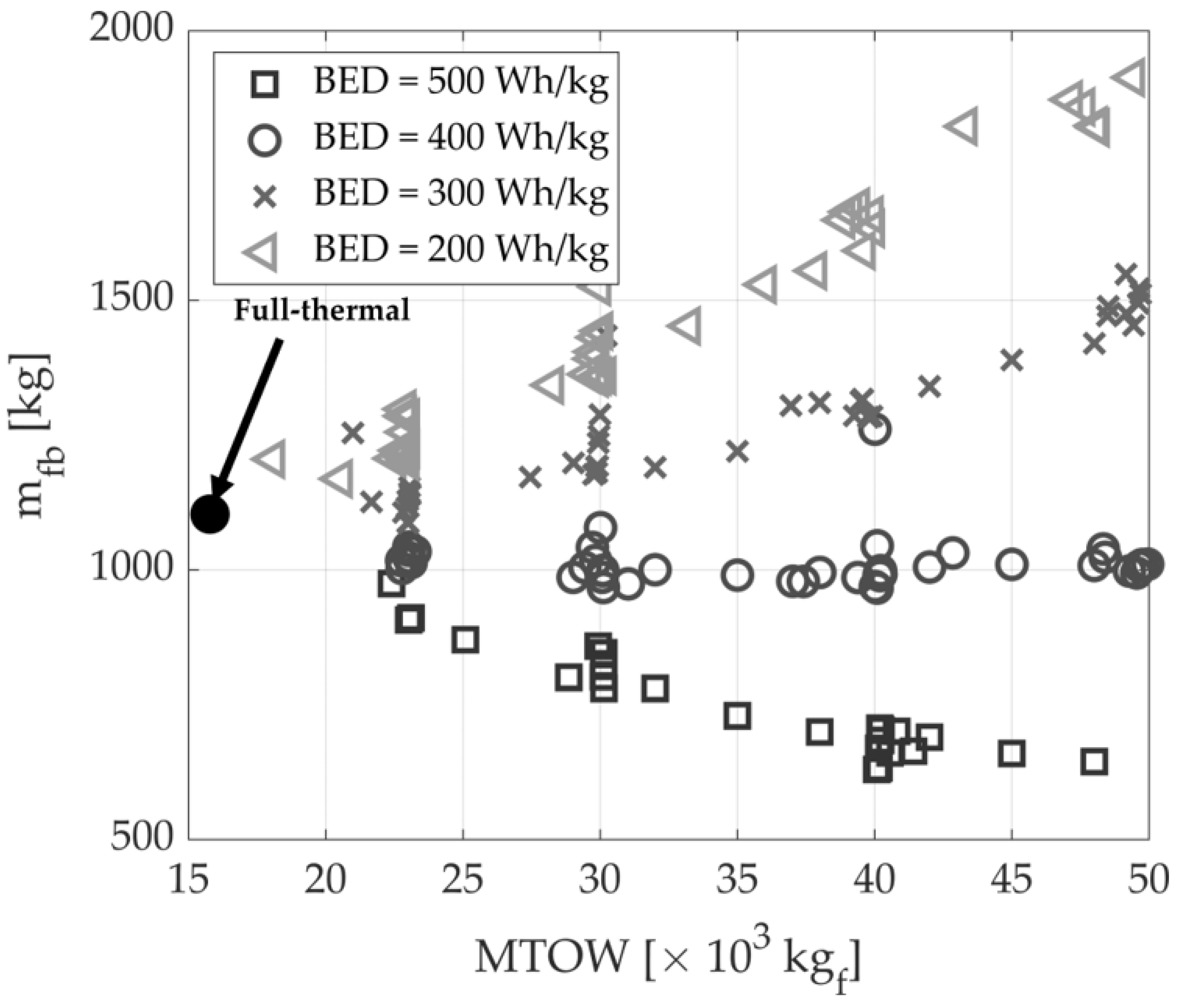
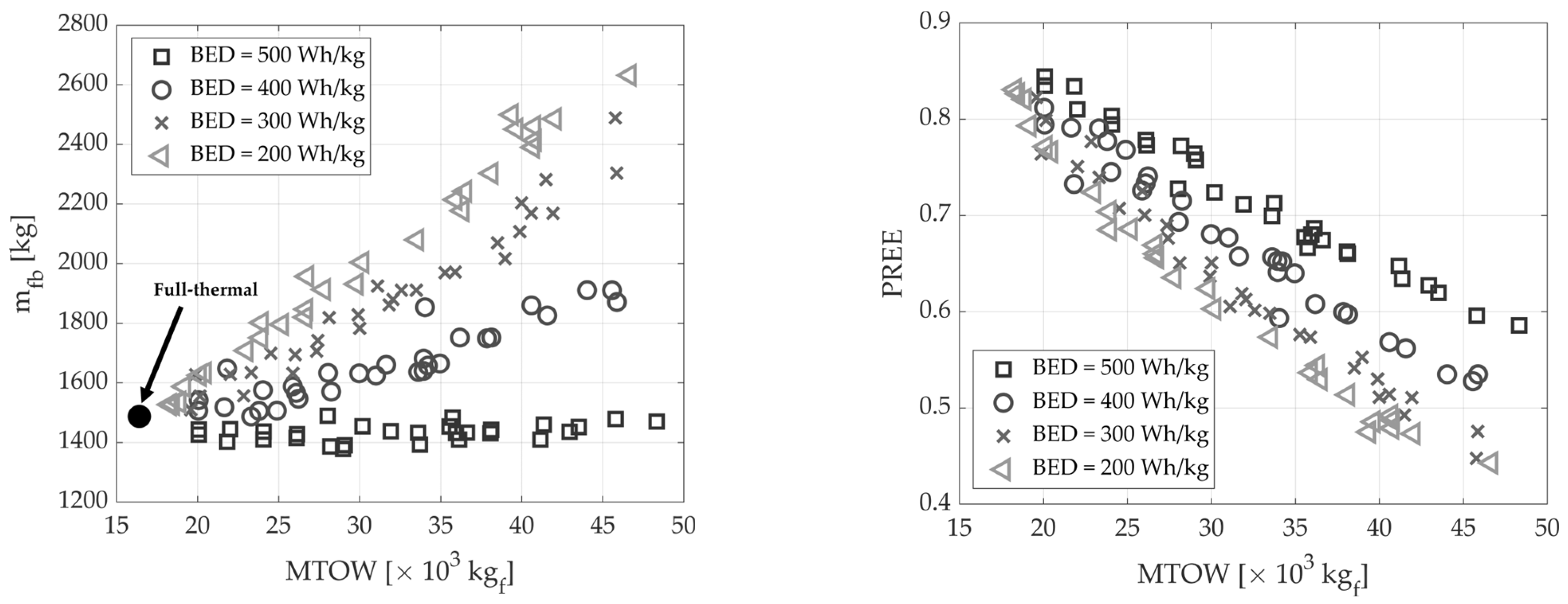
f interval. In this context, Figure 2 shows the trend of the optimal m fb obtained as a function of the value of W c .
From a technical standpoint, increasing the value of W c allows for an increase of the amount of the on-board battery power, hence allowing for the growth of the in-flight electrical power utilisation. The simulations results show a worsening trend in terms of m fb as W c   increases for values of the BED equal to 200 and 300 Wh/kg, bringing to light the fact that with these levels of battery technology, the penalties resulting from the weight increases due to the batteries are definitely greater than the benefits of using a share of electrical power to satisfy the energy required for the flight. For a value of the BED equal to 400 Wh/kg, the beneficial and detrimental effects seem to offset each other, resulting in no noticeable benefit in terms of m fb   as the possible number of batteries on board increases. The trend is inverted for a BED of 500 Wh/kg because the larger the number of batteries on board (hence the possibility of supplying electrical energy in flight), the higher the benefit in terms of m fb reduction.
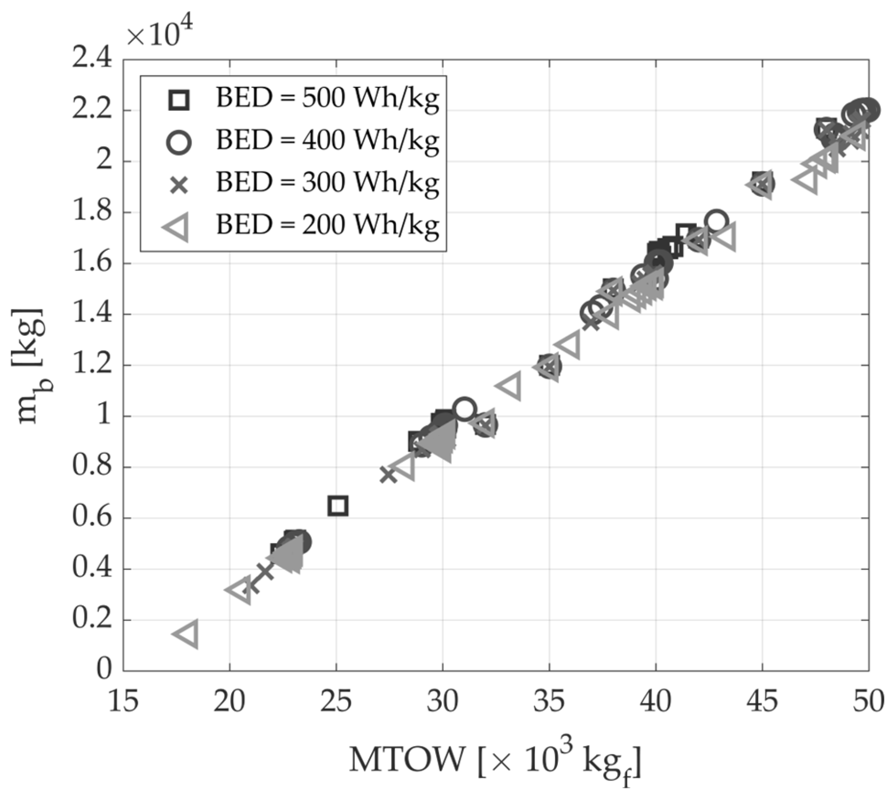
In other terms, the level of technological maturity of batteries defines the actual feasibility of regional hybrid–electric aircraft, if benefits in terms of m fb are the performance index. In fact, as shown in Figure 3, although increasing W c allows for similar on-board battery mass increases for all the values of BED considered, only the technological value predicted for 2035 provides significant fuel consumption reductions.
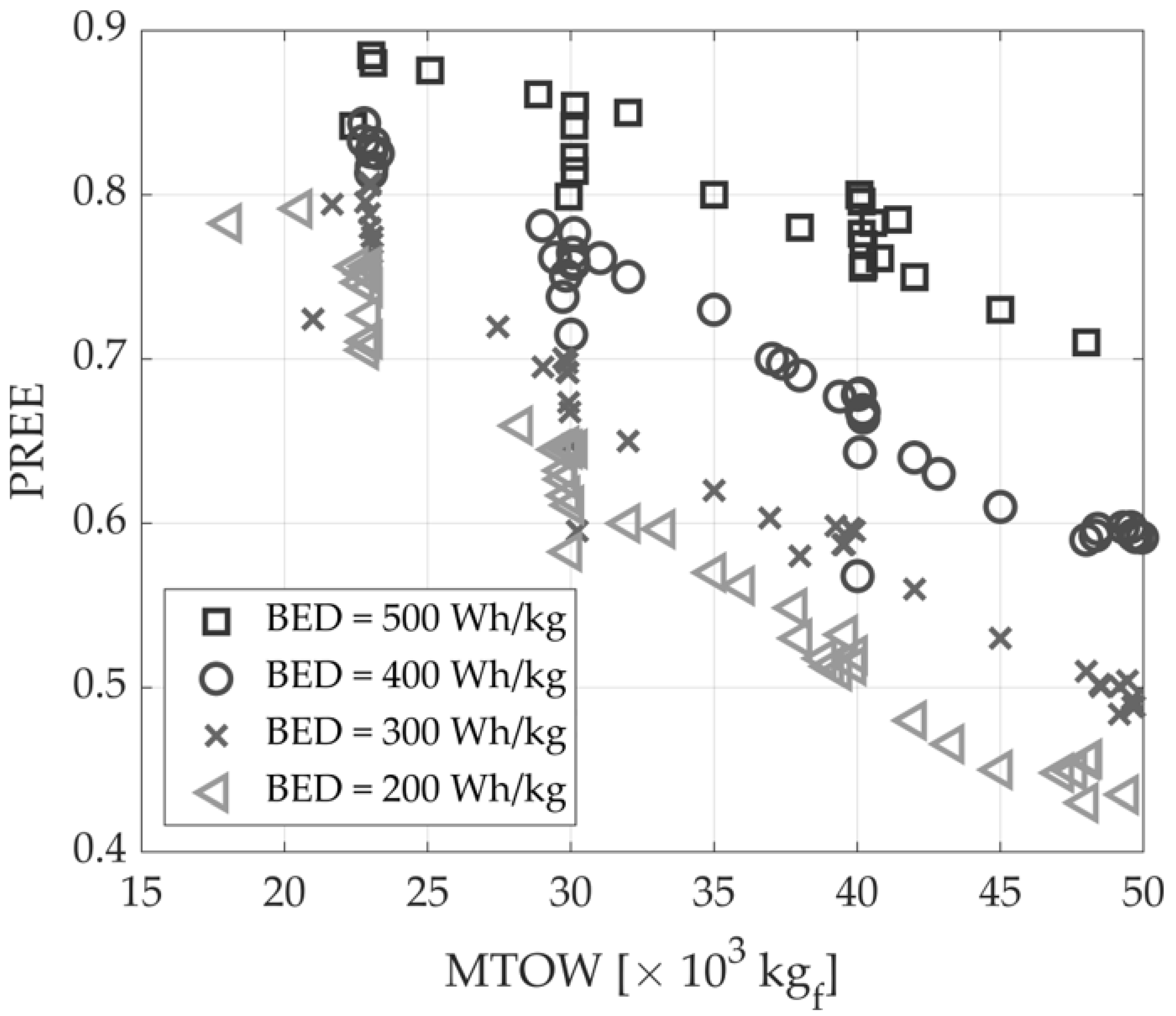
The trend between m fb and MTOW thus points to an observation regarding the energy efficiency of the hybrid–electric aircraft. In fact, for these optimised configurations, increases in MTOW correspond to reductions in PREE for all the BED values up to the forecasted reference for the 2035, as shown in Figure 4.
To discuss this contrast between metrics related to emissions ( m fb ) and those related to aircraft operating efficiency (PREE), a second set of optimisations in which the FoM to be maximized was set equal to the PREE was performed. In this context, Table 2 shows the obtained results.
Even for the PREE, if we consider the state of the art of the BED, the optimal results tend towards configuration with a low in-flight electric power supply, and a similar trend is found for a value of the BED equal to 300 Wh/kg. For these configurations, in fact, maximizing the lift-to-drag ratio (hence maximizing the W/S) and minimizing the take-off weight coincides with minimizing the energy required for flight E and, therefore, since the payload and range are fixed, with maximizing the PREE. The situation slightly varies for BED = 500 Wh/kg, for which the PREE-optimal configuration substantially differs from the m fb -optimal one. In fact, while exhibiting a non-negligible share of electrical power utilisation, the PREE optimum is far from that relevant to m fb and settles around much lower MTOW values. Once again, it is evident that for hybrid–electric aircraft, conflicts occur that differentiate sizing in the case of seeking solutions oriented towards reducing the fuel consumption (environmental benefits) or increasing the energy-efficiency metrics (operational benefits). To validate this hypothesis, also for the PREE optimisations, several runs were performed with the MTOW =   W c constraint, whose results are shown in Figure 5. In particular, for a value of the BED up to 300 Wh/kg, increasing W c   leads to penalisations in PREE, as the main contribution in increasing MTOW results in higher energy required to perform the mission. A slightly different trend is evident for BED values equal to 400 and 500 Wh/kg, where the maximum is obtained at W c   larger than the minimum values.
This occurs because there is a trade-off between the two different contributions to the energy required for flight because increasing W c results in a larger energy demand to trim the aircraft in flight, while on the other hand, it allows for an increase in the on-board battery mass and thus in a higher share of electric power supply. This aspect, for a parallel hybrid–electric powertrain, increases the total propulsive efficiency η p defined as
η p = 1 λ η t + λ η e η g
where 𝜆 is the ratio between the power supplied by the battery and the total supplied power [44]; while η t , η e , and η g are the efficiencies of the thermal engine, electric motor, and gearbox, respectively. In particular, as discussed in [
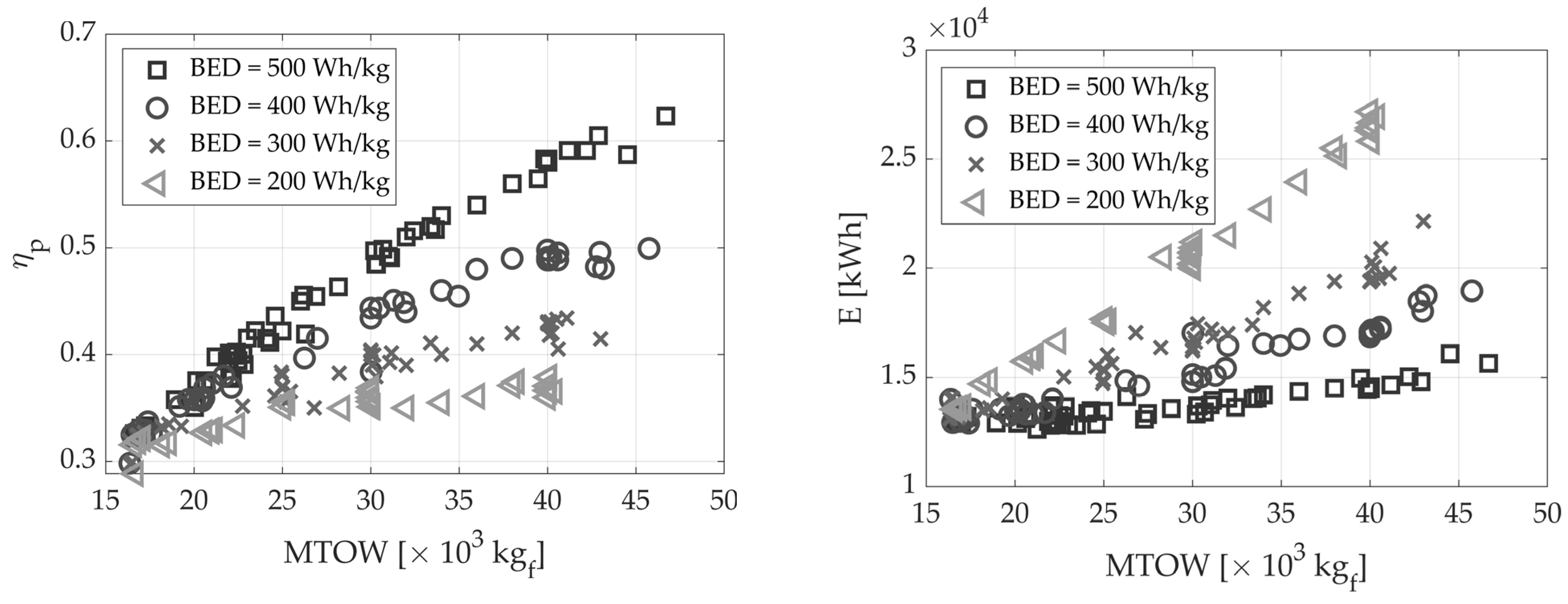
8], increases in 𝜆 (associated with increases in MTOW) imply increments of η p , as shown in Figure 6 on the left. This propulsive efficiency effect is, however, of minor significance on the overall requested flight energy for a value of the BED up to 300 Wh/kg, while it has a beneficial prevalence with respect to the increase in aircraft weight up to 22,000 kgf for the case with a value of the BED of 500 Wh/kg, where (slight) reductions of E can be observed (see the right part of Figure 6).
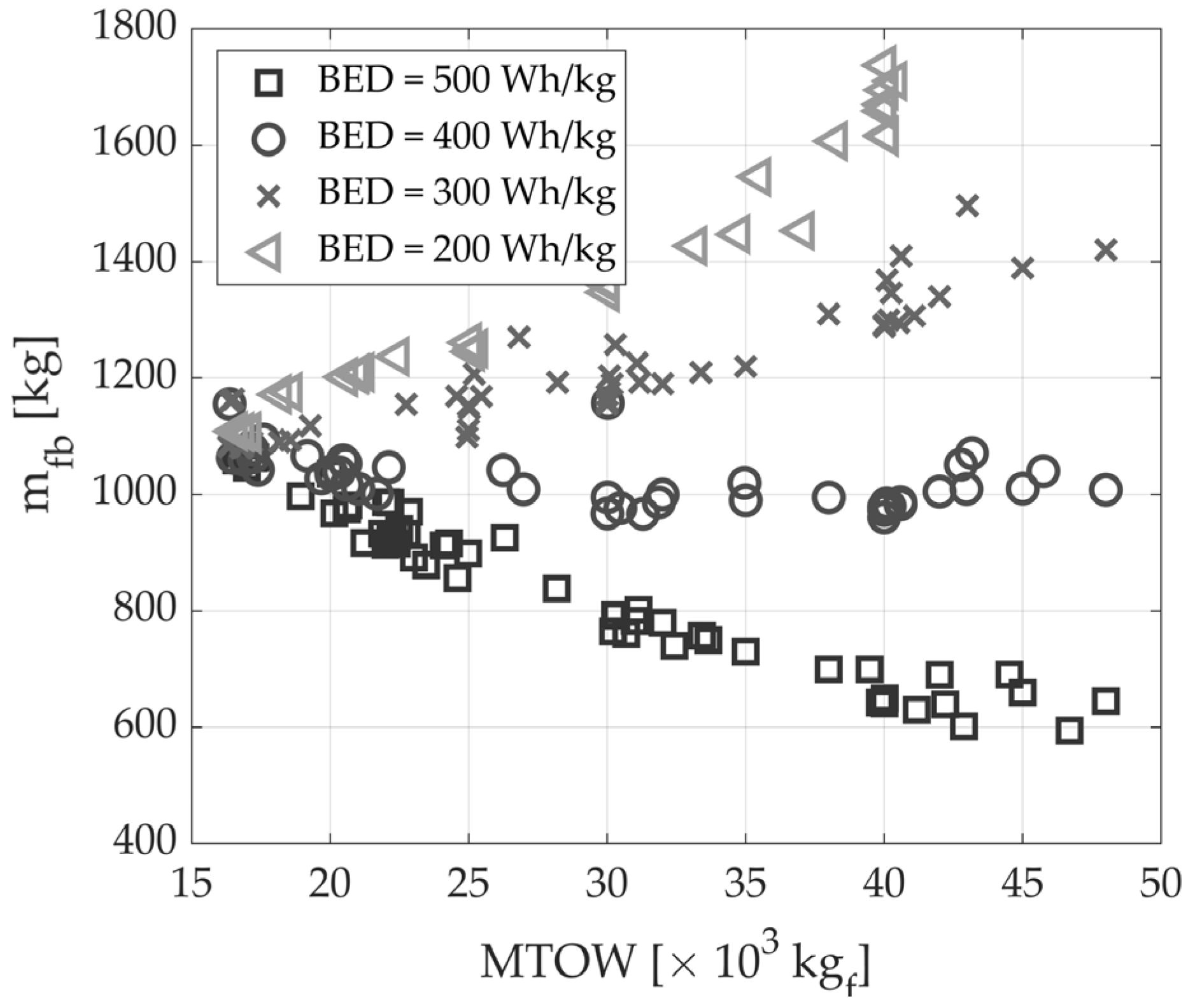
Figure 7 shows the results in terms of m fb for the PREE-optimised configurations, in which a similar trend (with respect to MTOW) to that obtained for the m fb -optimised configurations (see Figure 2) is observed.
Setting PREE as FoM, hence, may lead to a better utilisation of on-board power sources, providing energy-efficient aircraft operations. However, this conduces to solutions that are close to the thermal-powered aircraft if the current technology for batteries is considered and to a slightly lower-power hybridisation if the technology for 2035 is considered. This aspect does not lead to actual savings in terms of fuel consumption and hence is not an effective strategy to cut greenhouse gas emissions from regional aircraft operations. Indeed, the results here discussed highlight that a paradigm change in conceiving and developing regional hybrid–electric aircraft is necessary to reach the environmental targets for which this technology is under investigation. In fact, with current technology forecasts for 2035, it seems that accepting having a much higher MTOW (and hence energy consumption) than that of the state-of-the-art full-thermal aircraft turns out to be a necessary price to pay if actual emissions benefits are to be achieved. That conclusion is true if we consider only flight-related emissions. Indeed, even in the 2035 technological scenario, the higher energy quota necessary to cut fuel consumption, compatibly replaced by electric energy stored in the batteries, should come from renewable sources if an overall environmental benefit is to be attained.

3.1.2. Effect of Varying Design Range

This section describes the effect that design range variations have on the design and performance of regional hybrid–electric aircraft. First, the optimisations described in the previous section were replicated by reducing the design range to 400 nm. That value is representative of many typical missions in the regional market, as documented in [24]. We first present the results for the optimisations in which the FoM is set equal to the block fuel; then, different sets of optimisations were carried out again to vary the MTOW =   W c constraint. In Table 3, the results related to the optima– m fb configurations with a design range of 400 nm are reported.
The comparison with the corresponding results obtained for the reference range (namely, 600 nm, see Table 1 and Figure 2) reveals some substantial differences. First, since the energy demand to perform a shorter mission is lower, it is trivial to obtain general reductions in fuel consumption, which is obviously also true for full-thermal configuration. Note that for the full-thermal benchmark, MTOW = 15210 kgf, m fb   = 734 kg, and PREE = 0.871 are obtained. The differences are thus mainly to be found in the effect of the 
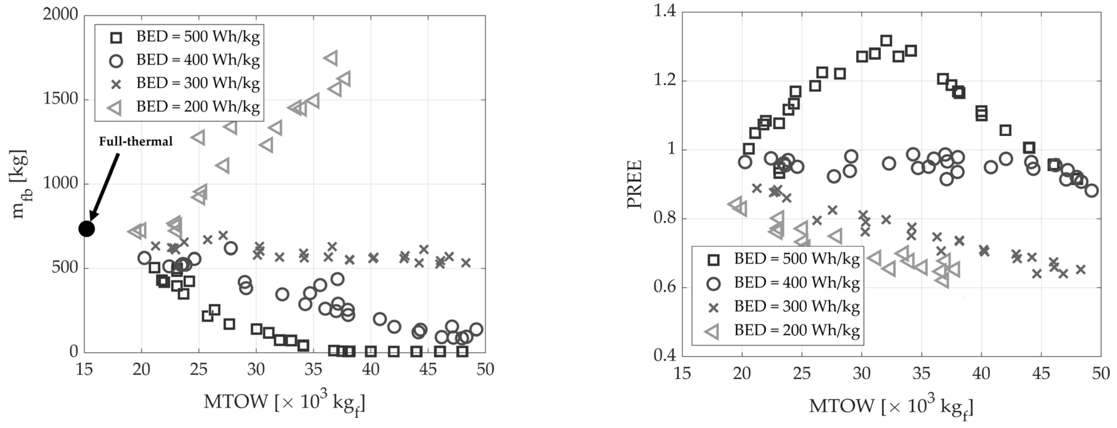
BED and MTOW variations. In fact, it can be observed that as MTOW increases, even substantial reductions in m fb can be obtained for BED = 400 Wh/kg (see the left part of Figure 8), a circumstance that did not occur at a range of 600 nm; slight reductions as MTOW changes are also visible for BED = 300 Wh/kg, which are in any case slight, but considerably better than the results relating to the state of the art in battery technology.
In particular, as MTOW increases, sharp reductions in m fb are obtained, both for BED 400 and 500 Wh/kg so that, with respect to the thermal benchmark, reductions of 88% (with an increase in MTOW of 210%) are obtained for BED = 400 Wh/kg, and even reductions of 97% (with an increase in MTOW of 146%) are achieved for the BED = 500 Wh/kg case. In this scenario, there is a m fb   = 10 kg, i.e., only the take-off share, while the standard airborne mission is fully accomplished with only electrical power. Regarding the values of PREE obtained for the m fb -optimised configurations (see the right part of Figure 8), the numerical results show that in case of BED = 500 Wh/kg, the value of the PREE increases until it reaches a maximum of 1.3 for an MTOW near 32,000 kgf, then the trend is reversed and PREE decreases. In this case, a more beneficial trade-off between the two FoMs can be selected, as a very low m fb corresponds with the maximum PREE. In the case of BED = 400 Wh/kg, PREE is almost constant for the investigated interval of MTOW, and for lower values of BED, a decreasing trend is still observed, as for the case of 600 nm.
Interesting considerations can also be made by evaluating the results for the case where FoM is set equal to PREE for the 400 nm design range. The results for the PREE optima are reported in Table 4, and the trend for the optimisation sets with the constraint MTOW =   W c is reported in Figure 9. In particular, with respect to the reference case with a design range of 600 nm, in this scenario, increasing the MTOW resulted in combined improvements in both the PREE and m fb for BED = 500 Wh/kg; for the PREE optimum, a m fb   = 52 kg and a PREE = 1.335 with a MTOW = 32,686 kgf are obtained; the trend of PREE with respect to MTOW (see the right part of Figure 9) increases up to this maximum, then it starts to rapidly decrease. In the reference case (i.e., 600 nm), on the other hand, increasing the MTOW resulted in a very slight, almost imperceptible, peak with a similar trend to that seen for the case at BED = 300 Wh/kg for the reduced range.
Reducing the range to 400 nm, therefore, would enable an effective implementation of hybrid–electric propulsion with BED values reasonably achievable in the next decade. Configurations with potentially low-to-zero fuel consumption in the operating mission can be achieved by considering reduced values for the design range, which in any case would cover the largest share of the regional market [24]. Furthermore, as demonstrated in [36], design range extensions can easily be obtained for hybrid–electric aircraft with parallel powertrain architecture, at the expense of a slight oversizing of the thermal propulsion unit and/or a higher m fb in these extended-range conditions, considered as off-design routes.
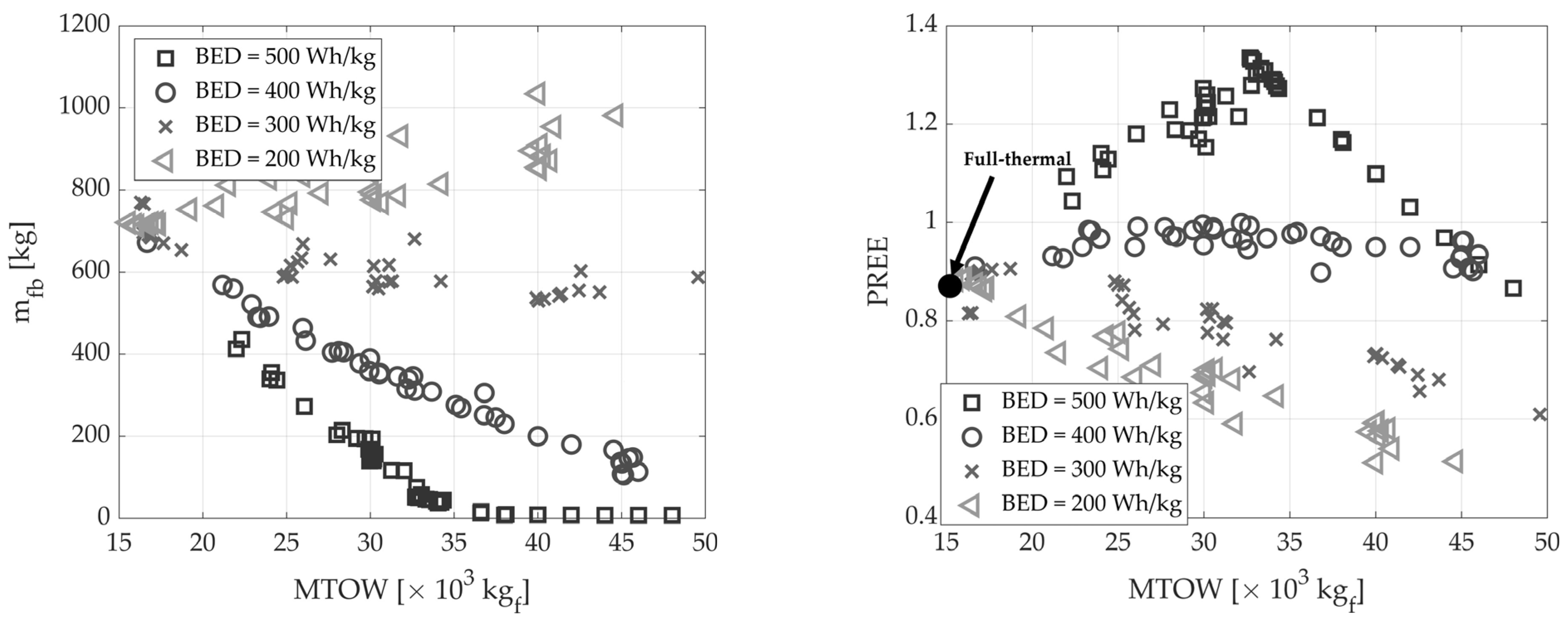
Increasing the design range with respect to the reference case, on the other hand, leads to opposite observations. This is evident from the trends in Figure 10 and the results in Table 5, obtained by applying the optimisation procedure described in Section 2, using FoM equal to m fb for a design range of 800 nm. In addition to the obvious increase in m fb due to the higher energy demand of the route, there are substantial differences compared to the 600 nm and 400 nm cases. Specifically, increasing the MTOW does not introduce any significative benefit in terms of m fb for any BED value (not even for the most optimistic forecast), as shown in the left part of Figure 10. In fact, the opposite effect is obtained, with deteriorations in fuel consumption for all BED values except for BED = 500 W/kg, where an almost indifferent trend is obtained. In general, even in this latter case, increasing MTOW does not bring any benefit, as there is also an associated penalty in terms of the PREE (see the right part of Figure 10). With respect to the thermal benchmark, which exhibits an MTOW = 16,404 kgf, an m fb   = 1487 kg, and a PREE = 0.859, reductions in m fb of 6.7% (with an increase in MTOW of 77%) are obtained for BED = 500 Wh/kg, hence not introducing significant overall benefits in this regard, nor are there any benefits in terms of PREE (see the right part of Figure 10).
To summarize, Table 6 reports a concise comparison of the main performance of the m fb -optimised configurations varying BED and design range.
From the previous analyses and discussion, it is apparent that there are three distinct and interdependent boundaries that define a confined field for the effective implementation of hybrid–electric propulsion for regional transport aircraft. The first refers to battery technology development and points out that BED values (at battery pack level) of 500 Wh/kg must be achieved if effective and efficient integration of hybrid–electric propulsion on transport aircraft is to be envisaged. This is not sufficient unless the aircraft design requirements are properly tuned. In particular, benefits in terms of fuel consumption begin to be achieved if design ranges up to 600 nm are considered. Reducing the range to 400 nm leads to marked improvements in fuel consumption on the standard mission, at the expense of reductions in the aircraft operating capabilities. However, even with these reduced design range values (i.e., 400 nm), most of the typical routes in the current regional sector would be covered. Increasing the design range above 600 nm, on the other hand, would compromise the effectiveness of the integration of hybrid–electric propulsion, as there are no advantages to be gained in terms of fuel consumption and, therefore, no benefit from the reduction of greenhouse gas emissions viewpoint, which is indeed the driver for the development of this technology. The third element required for an effective implementation of hybrid–electric propulsion relates to the selection of figures of merit steering the design process. Specifically, it is highlighted that the technological and weight limitations of batteries need to be overcome through a paradigm shift in design development, in which increases in aircraft weight and reductions in energy efficiency must be taken into account if fuel consumption and related direct greenhouse emissions are to be minimised.

4. Conclusions

The aim of this paper was to identify the feasibility boundaries of regional hybrid–electric aircraft at a conceptual stage. Battery performance, in terms of gravimetric energy density, represents a bottleneck for the effective application of hybrid–electric propulsion in transport aviation. In this paper, a sensitivity analysis in this regard was conducted by considering the design of regional hybrid–electric aircraft equipped with a parallel powertrain. There are two main conclusions that can be summarized from this sensitivity analysis of the results presented in this paper. On the one hand, a clear limitation of the design space is identified, forced by the technological maturity of the batteries, which does not allow for significant reductions in fuel consumption to be achieved unless the BED value of 500 Wh/kg, at pack level, is reached. On the other hand, it emerges that there is a need to change the design paradigm of such aircraft if benefits in terms of reducing greenhouse emissions are to be effectively reached. Specifically, penalties in terms of take-off weight and overall aircraft energy efficiency should be allowed for if real benefits in terms of reducing flight-related emissions are to be achieved. Furthermore, reducing the design range, and hence the operating capability of the regional aircraft, may lead to a substantial reduction in fuel consumption and direct greenhouse gas emissions. That trade-off is crucial and needs to be deeply addressed during the initial phases of the design process of such an innovative aircraft concept.

Author Contributions

Conceptualization, K.A.S., G.P. and A.A.Q.; methodology, G.P. and K.A.S.; software, G.P. and K.A.S.; formal analysis, K.A.S. and G.P.; investigation, G.P. and K.A.S.; data curation, G.P. and K.A.S.; writing—original draft preparation, K.A.S. and G.P.; writing—review and editing, A.A.Q.; visualization, G.P. and K.A.S.; supervision, G.P., K.A.S. and A.A.Q. All authors have read and agreed to the published version of the manuscript.

Funding

This research received no external funding.

Institutional Review Board Statement

Not applicable.

Informed Consent Statement

Not applicable.

Data Availability Statement

The data presented in this study are available on request from the authors.

Conflicts of Interest

The authors declare no conflict of interest.

Abbreviations

List of SymbolsDescriptionUnit
EEnergy to accomplish the missionJ
gStandard gravitym/s2
H P Degree of hybridisation
L/DLift-to-drag ratio
m b Battery masskg
m fb Block fuel masskg
m p Payload masskg
P/WSpecific powerW/kgf
P i e Electric motor installed powerW
P i t Thermal engine installed powerW
P t Supplied thermal powerW
R Rangenm
WAircraft weightN
W/SWing loadingkgf/m2
η e Efficiency electric chain
η g Gearbox efficiency
η p Propulsion system efficiency
η t Efficiency thermal chain
λ Source power ratio
Φ e Power fraction supplied by the electric motor
Φ t Power fraction supplied by the thermal engine
List of acronymsDescriptionUnit
BEDGravimetric battery energy densityWh/kg
FoMFigure of merit
MTOWMaximum take-off weightkgf
PREEPayload-range efficiency

References

  1. Lee, D.; Pitari, G.; Grewe, V.; Gierens, K.; Penner, J.; Petzold, A.; Prather, M.; Schumann, U.; Bais, A.; Berntsen, T.; et al. Transport impacts on atmosphere and climate: Aviation. Atmospheric Environ. 2010, 44, 4678–4734. [Google Scholar] [CrossRef] [PubMed]
  2. Hudda, N.; Durant, L.W.; Fruin, S.A.; Durant, J.L. Impacts of Aviation Emissions on Near-Airport Residential Air Quality. Environ. Sci. Technol. 2020, 54, 8580–8588. [Google Scholar] [CrossRef] [PubMed]
  3. Hasan, A.; Al Mamun, A.; Rahman, S.M.; Malik, K.; Al Amran, I.U.; Khondaker, A.N.; Reshi, O.; Tiwari, S.P.; Alismail, F.S. Climate Change Mitigation Pathways for the Aviation Sector. Sustainability 2021, 13, 3656. [Google Scholar] [CrossRef]
  4. Tasca, A.L.; Cipolla, V.; Abu Salem, K.; Puccini, M. Innovative Box-Wing Aircraft: Emissions and Climate Change. Sustainability 2021, 13, 3282. [Google Scholar] [CrossRef]
  5. Ciliberti, D.; Della Vecchia, P.; Memmolo, V.; Nicolosi, F.; Wortmann, G.; Ricci, F. The Enabling Technologies for a Quasi-Zero Emissions Commuter Aircraft. Aerospace 2022, 9, 319. [Google Scholar] [CrossRef]
  6. Proesmans, P.-J.; Vos, R. Airplane Design Optimization for Minimal Global Warming Impact. J. Aircr. 2022, 59, 1363–1381. [Google Scholar] [CrossRef]
  7. Brelje, B.J.; Martins, J.R. Electric, hybrid, and turboelectric fixed-wing aircraft: A review of concepts, models, and design approaches. Prog. Aerosp. Sci. 2018, 104, 1–19. [Google Scholar] [CrossRef]
  8. Abu Salem, K.; Palaia, G.; Quarta, A.A. Review of hybrid-electric aircraft technologies and designs: Critical analysis and novel solutions. Prog. Aerosp. Sci. 2023, 141, 100924. [Google Scholar] [CrossRef]
  9. Zhang, X.; Bowman, C.L.; O’Connell, T.C.; Haran, K.S. Large electric machines for aircraft electric propulsion. IET Electr. Power Appl. 2018, 12, 767–779. [Google Scholar] [CrossRef]
  10. Sahoo, S.; Zhao, X.; Kyprianidis, K. A Review of Concepts, Benefits, and Challenges for Future Electrical Propulsion-Based Aircraft. Aerospace 2020, 7, 44. [Google Scholar] [CrossRef]
  11. Barzkar, A.; Ghassemi, M. Electric Power Systems in More and All Electric Aircraft: A Review. IEEE Access 2020, 8, 169314–169332. [Google Scholar] [CrossRef]
  12. Wheeler, P.; Sirimanna, T.S.; Bozhko, S.; Haran, K.S. Electric/Hybrid-Electric Aircraft Propulsion Systems. Proc. IEEE 2021, 109, 1115–1127. [Google Scholar] [CrossRef]
  13. Abu Salem, K.; Palaia, G.; Quarta, A.A.; Chiarelli, M.R. Medium-Range Aircraft Conceptual Design from a Local Air Quality and Climate Change Viewpoint. Energies 2023, 16, 4013. [Google Scholar] [CrossRef]
  14. Voskuijl, M.; van Bogaert, J.; Rao, A.G. Analysis and design of hybrid electric regional turboprop aircraft. CEAS Aeronaut. J. 2018, 9, 15–25. [Google Scholar] [CrossRef]
  15. Eisenhut, D.; Windels, E.; Reis, R.; Bergmann, D.; Ilário, C.; Palazzo, F.; Strohmayer, A. Foundations towards the future: FutPrInt50 TLARs an open approach. IOP Conf. Series Mater. Sci. Eng. 2021, 1024, 012069. [Google Scholar] [CrossRef]
  16. Brdnik, A.P.; Kamnik, R.; Marksel, M.; Božičnik, S. Market and Technological Perspectives for the New Generation of Regional Passenger Aircraft. Energies 2019, 12, 1864. [Google Scholar] [CrossRef]
  17. Friedrich, C.; Robertson, P. Hybrid-Electric Propulsion for Aircraft. J. Aircr. 2015, 52, 176–189. [Google Scholar] [CrossRef]
  18. Hoelzen, J.; Liu, Y.; Bensmann, B.; Winnefeld, C.; Elham, A.; Friedrichs, J.; Hanke-Rauschenbach, R. Conceptual Design of Operation Strategies for Hybrid Electric Aircraft. Energies 2018, 11, 217. [Google Scholar] [CrossRef]
  19. Pornet, C.; Isikveren, A. Conceptual design of hybrid-electric transport aircraft. Prog. Aerosp. Sci. 2015, 79, 114–135. [Google Scholar] [CrossRef]
  20. Sgueglia, A.; Schmollgruber, P.; Bartoli, N.; Benard, E.; Morlier, J.; Jasa, J.; Martins, J.R.R.A.; Hwang, J.T.; Gray, J.S. Multidisciplinary Design Optimization Framework with Coupled Derivative Computation for Hybrid Aircraft. J. Aircr. 2020, 57, 715–729. [Google Scholar] [CrossRef]
  21. Finger, D.F.; Braun, C.; Bil, C. Comparative assessment of parallel–hybrid–electric propulsion systems for four different aircraft. J. Aircr. 2020, 57. [Google Scholar] [CrossRef]
  22. Decerio, D.P.; Hall, D.K. Benefits of Parallel Hybrid Electric Propulsion for Transport Aircraft. IEEE Trans. Transp. Electrif. 2022, 8, 4054–4066. [Google Scholar] [CrossRef]
  23. De Vries, R.; Brown, M.; Vos, R. Preliminary Sizing Method for Hybrid-Electric Distributed-Propulsion Aircraft. J. Aircr. 2019, 56, 2172–2188. [Google Scholar] [CrossRef]
  24. Eisenhut, D.; Moebs, N.; Windels, E.; Bergmann, D.; Geiß, I.; Reis, R.; Strohmayer, A. Aircraft Requirements for Sustainable Regional Aviation. Aerospace 2021, 8, 61. [Google Scholar] [CrossRef]
  25. Della Vecchia, P.; Nicolosi, F. Aerodynamic guidelines in the design and optimization of new regional turboprop aircraft. Aerosp. Sci. Technol. 2014, 38, 88–104. [Google Scholar] [CrossRef]
  26. Nicolosi, F.; Corcione, S.; Trifari, V.; De Marco, A. Design and Optimization of a Large Turboprop Aircraft. Aerospace 2021, 8, 132. [Google Scholar] [CrossRef]
  27. Palaia, G.; Abu Salem, K.; Quarta, A.A. Comparative Analysis of Hybrid-Electric Regional Aircraft with Tube-and-Wing and Box-Wing Airframes: A Performance Study. Appl. Sci. 2023, 13, 7894. [Google Scholar] [CrossRef]
  28. Meindl, M.; de Ruiter, C.; Marciello, V.; Di Stasio, M.; Hilpert, F.; Ruocco, M.; Nicolosi, F.; Thonemann, N.; Saavedra-Rubio, K.; Locqueville, L.; et al. Decarbonised Future Regional Airport Infrastructure. Aerospace 2023, 10, 283. [Google Scholar] [CrossRef]
  29. Palaia, G.; Zanetti, D.; Abu Salem, K.; Cipolla, V.; Binante, V. THEA-CODE: A design tool for the conceptual design of hybrid-electric aircraft with conventional or unconventional airframe configurations. Mech. Ind. 2021, 22, 19. [Google Scholar] [CrossRef]
  30. Drela, M.; Youngren, H. AVL 3.36 User Primer, 3.36; Online Software Manual; Massachusetts Institute of Technology: Massachusetts, CA, USA, 2017. Available online: https://web.mit.edu/drela/Public/web/avl/AVL_User_Primer.pdf (accessed on 28 August 2023).
  31. Raymer, P. Aircraft Design: A Conceptual Approach; AIAA Education Series; American Institute of Aeronautics & Ast.: Washington, DC, USA, 1992; ISBN 0–930403–51–7. [Google Scholar]
  32. Cipolla, V.; Abu Salem, K.; Palaia, G.; Binante, V.; Zanetti, D. A DoE-based approach for the implementation of structural surrogate models in the early stage design of box-wing aircraft. Aerosp. Sci. Technol. 2021, 117, 106968. [Google Scholar] [CrossRef]
  33. Wells, D.; Horvath, B.; McCullers, L. The Flight Optimization System Weights Estimation Method; NASA Technical Report; NASA: Washington, DC, USA, 2017. Available online: https://ntrs.nasa.gov/citations/20170005851 (accessed on 28 August 2023).
  34. Torenbeek, E. Development and Application of a Comprehensive, Design Sensitive Weight Prediction Method for Wing Struc-tures of Transport Category Aircraft; Report LR–693; Delft University of Technology: Delft, The Netherlands, 1992. [Google Scholar]
  35. Sforza, P. Commercial Airplane Design Principles; Elsevier: Amsterdam, The Netherlands, 2014. [Google Scholar] [CrossRef]
  36. Palaia, G.; Abu Salem, K. Mission Performance Analysis of Hybrid-Electric Regional Aircraft. Aerospace 2023, 10, 246. [Google Scholar] [CrossRef]
  37. Martins, J.R.; Ning, A. Engineering Design Optimization; Cambridge University Press: Cambridge, UK, 2021; ISBN 978–1108833417. [Google Scholar]
  38. Zhao, L.; Lakraychi, A.E.; Chen, Z.; Liang, Y.; Yao, Y. Roadmap of Solid-State Lithium-Organic Batteries toward 500 Wh kg–1. ACS Energy Lett. 2021, 6, 3287–3306. [Google Scholar] [CrossRef]
  39. Marciello, V.; Di Stasio, M.; Ruocco, M.; Trifari, V.; Nicolosi, F.; Meindl, M.; Lemoine, B.; Caliandro, P. Design Exploration for Sustainable Regional Hybrid-Electric Aircraft: A Study Based on Technology Forecasts. Aerospace 2023, 10, 165. [Google Scholar] [CrossRef]
  40. Löbberding, H.; Wessel, S.; Offermanns, C.; Kehrer, M.; Rother, J.; Heimes, H.; Kampker, A. From Cell to Battery System in BEVs: Analysis of System Packing Efficiency and Cell Types. World Electr. Veh. J. 2020, 11, 77. [Google Scholar] [CrossRef]
  41. Xue, N.; Du, W.; Martins, J.R.R.A.; Shyy, W. Lithium-Ion Batteries: Thermomechanics, Performance, and Design Optimization. In Handbook of Clean Energy Systems; Encyclopedia of Aircraft Engineering, Green Aviation; John Wiley & Sons, Ltd.: Hoboken, NJ, USA, 2015; pp. 1–16. [Google Scholar] [CrossRef]
  42. Dever, T.; Duffy, K.; Provenza, A.J.; Loyselle, P.L.; Choi, B.B.; Morrison, C.R.; Lowe, A.M. Assessment of Technologies for Noncryogenic Hybrid Electric Propulsion; Report NASA, TP–2015–216588; NASA: Washington, DC, USA, 2015. Available online: https://ntrs.nasa.gov/citations/20150000747 (accessed on 28 August 2023).
  43. Zhang, H.; Li, X.; Zhang, H. Li–S and Li–O2 Batteries with High Specific Energy; Springer: Singapore, 2017; pp. 1–48. [Google Scholar] [CrossRef]
  44. Isikveren, A.; Kaiser, S.; Pornet, C.; Vratny, P. Pre-design strategies and sizing techniques for dual-energy aircraft. Aircr. Eng. Aerosp. Technol. 2014, 86, 525–542. [Google Scholar] [CrossRef]
Figure 1. Conceptual sketch of hybrid–electric aircraft power supply strategy (adapted from [36]).
Applsci 13 11113 g001
Figure 2. m fb   vs. MTOW varying BED, for optimisations with FoM ≜   m fb @600 nm.
Applsci 13 11113 g002
Figure 3. m b   vs. MTOW varying BED, for optimisations with FoM ≜   m fb @600 nm.
Applsci 13 11113 g003
Figure 4. PREE vs. MTOW varying BED, for optimisations with FoM ≜   m fb @600 nm.
Applsci 13 11113 g004
Figure 5. PREE vs. MTOW varying BED, for optimisations with FoM ≜ PREE @600 nm.
Applsci 13 11113 g005
Figure 6. Parallel hybrid–electric powertrain η (left), total energy supplied (right) @600 nm.
Applsci 13 11113 g006
Figure 7. m fb vs. MTOW varying BED, for optimisations with FoM ≜ PREE @600 nm.
Applsci 13 11113 g007
Figure 8. m fb   (left), PREE vs. MTOW (right) varying BED; optimisations with FoM ≜   m fb , @400 nm.
Applsci 13 11113 g008
Figure 9. m fb   (left), PREE vs. MTOW (right) varying BED; optimisations with FoM ≜ PREE @400 nm.
Applsci 13 11113 g009
Figure 10. m fb   vs. MTOW (left), PREE vs. MTOW (right) varying BED, for optimisations with FoM ≜   m fb @800 nm.
Applsci 13 11113 g010
Table 1. Main data of m fb -optimised configurations varying BED @600 nm.
BED (Wh/kg) m fb (kg)MTOW (kgf) H P W / S (kgf/m2) Φ cl t Φ cl e Φ cr t Φ cr e Φ de t Φ de e
200109717,0310.1393250.5480.4340.46600.2390.412
300107317,4620.2093250.5590.4170.47100.1720.580
40096730,1160.4583250.1510.9080.4330.2080.1480.220
50052550,2110.4593250.0880.9460.1310.5240.1040.195
Table 2. Main data of PREE-optimised configurations varying BED @600 nm.
BED (Wh/kg)PREEMTOW (kgf) H P W / S (kg/m2) Φ cl t Φ cl e Φ cr t Φ cl e Φ de t Φ de e
2000.85916,5910.0843250.5010.9100.41500.3260.061
3000.88216,3390.1523250.5570.4150.46000.2930.189
4000.89217,3930.2093250.4960.6590.47300.1750.572
5000.89921,9950.4033250.2940.8390.4710.1730.1940.249
Table 3. Main data of m fb -optimised configurations varying BED @400 nm.
BED (Wh/kg) m fb (kg)MTOW (kgf) H P W / S (kg/m2) Φ cl t Φ cl e Φ cr t Φ cl e Φ de t Φ de e
20071818,6070.1363250.4560.5250.4260.3670.1530.244
30052546,0210.4083250.1260.4820.1970.3130.1600.149
4008947,2040.4853250.1180.4830.010.3140.090.148
5001037,4880.69432500.70800.46700.236
Table 4. Main data of PREE-optimised configurations varying BED @400 nm.
BED (Wh/kg)PREEMTOW (kgf) H P W / S (kg/m2) Φ cl t Φ cl e Φ cr t Φ cl e Φ de t Φ de e
2000.88915,9180.083220.5590.4060.42900.2380
3000.90817,6510.2033250.4320.9130.4700.2150.399
4001.00135,1020.3753250.18310.0880.7140.1630.165
5001.33532,6860.4213250.1261010.1260.779
Table 5. Main data of m fb -optimised configurations varying BED @800 nm.
BED (Wh/kg) m fb (kg)MTOW (kgf) H P W / S (kg/m2) Φ cl t Φ cl e Φ cr t Φ cl e Φ de t Φ de e
200152718,2770.1633250.4930.6930.43800.2910.122
300150919,5780.3023240.4090.7940.51800.2920.131
400150720,0400.3383250.5200.5160.5300.0150.0880.676
500137828,9770.3373250.24210.3490.2890.1350.282
Table 6. Summary of the comparison of main results for hybrid–electric m fb -optimised regional configurations, varying BED and range.
BED (Wh/kg)MTOW (kgf) m fb (kg)PREE
400 nm600 nm800 nm400 nm600 nm800 nm400 nm600 nm800 nm
Full-thermal15,21015,78316,404734110314870.8710.8690.859
20018,60717,03118,277718109715270.8510.8620.828
30046,02117,46219,578525107315090.6750.8730.823
40047,20430,11620,0408996715070.9410.7770.812
50037,48850,21128,9771052513781.1880.7290.764
Disclaimer/Publisher’s Note: The statements, opinions and data contained in all publications are solely those of the individual author(s) and contributor(s) and not of MDPI and/or the editor(s). MDPI and/or the editor(s) disclaim responsibility for any injury to people or property resulting from any ideas, methods, instructions or products referred to in the content.

