Article

Experimental Testing and Residual Performance Evaluation of Existing Hangers with Steel Pipe Protection Taken from an In-Service Tied-Arch Bridge

1
College of Transportation Science & Engineering, Nanjing Tech University, Nanjing 211800, China
2
College of Architecture Science and Engineering, Yangzhou University, Yangzhou 225127, China
3
Transportation Science Institute of Nanjing University of Technology (Chuzhou) Co., Ltd., Chuzhou 239050, China
4
Department of Civil and Environmental Engineering, University of California, Los Angeles, CA 90095, USA
5
School of Civil Engineering, Southwest Jiaotong University, Chengdu 610031, China
6
School of Transportation, Southeast University, Nanjing 211189, China
*
Authors to whom correspondence should be addressed.
These authors contributed equally to this work.
Appl. Sci. 2023, 13(19), 11070; https://doi.org/10.3390/app131911070
Submission received: 28 August 2023 / Revised: 29 September 2023 / Accepted: 4 October 2023 / Published: 8 October 2023
(This article belongs to the Special Issue Advances in Bridge Design and Structural Performance)

Abstract

:
Background: Tied-arch bridges’ hangers are crucial load-bearing parts, and their excellent condition directly influences bridge safety. However, assessing in-service hangers’ continuing functional performance is irrelevant and incomplete, particularly for unique hangers covered by outer steel tubes. Objective: This research uses a case study of an under-bearing tied-arch bridge with substantial hanger damage to determine the origin of the damage and analyze the hanger’s remaining operational ability. Methodology/approach: This study presents a set of assessment methodologies and procedures for in-service hangers’ remaining functioning performance using field inspection and indoor tests. First, an appearance inspection of the full bridge hanger’s upper and lower anchor heads was carried out, and the categories of anchor head damage and distribution rules are summarized. The causes of major water damage and the lower anchor head’s water infiltration channel were explored. Then, a full interior test was performed on the disassembled sick hanger to establish its present mechanical qualities. Finally, field inspection and indoor test findings assessed the bridge hanger’s operational performance. The findings suggest that the anchor box drainage prevention system should be improved to prevent rainfall and condensation from pooling in the lower anchor box and causing anticorrosive grease failure and anchor head corrosion. Results: The hanger’s mechanical qualities have deteriorated and no longer meet usage standards. Most of the water accumulated in the anchor head of the conventional construction hanger enters from the bridge deck or rope surface, but because of the outer steel pipe, rainwater can flow into the lower anchor box through the upper anchor box along the gap between the hanger and the outer steel pipe, so the waterproof system of the upper anchor box should be checked. Conclusions: This research may be used for safety evaluation and maintenance of the same hanger in service.

1. Introduction

Cable-supported systems are usually used in long-span bridges. Cables (including suspenders and hangers) are important force-transmission components of cable-supported bridges. Their good working conditions directly affect the structural safety of bridges. Figure 1 presents a typical cable-supported bridge and its components. Bridge operation time, construction defects, environmental impact, maintenance not being carried out, and other reasons will cause different degrees of disease. These diseases usually accelerate the aging of the cable and reduce its service life.
The tension cables are typically situated outside the girders, with a small cross-section and long-term high-stress conditions, making them highly corrosion-resistant. The corrosion resistance of the cables greatly affects the safety and durability of cable-bearing bridges. There are numerous cases of bridge damage or even collapse due to corrosion or fracture of the cable-stayed bridge, and the service life of most cable-stayed bridges is less than their designed service life, as determined by a literature search and an analysis of engineering cases. The Jinsha River Bridge in Yibin City is a tied-arch bridge, and eight hanger rods at its end broke due to extensive corrosion, causing the bridge superstructure to collapse. Figure 2 depicts the corrosion of the steel strand and hanger bar anchorage end.
Studies indicate that large prestressed girder self-anchored suspension bridges are appropriate where external anchorage systems cannot be provided. However, these bridges cannot surmount the theat that their hangers will break unexpectedly under hazardous working conditions, posing the danger of continuous collapse. On the afternoon of 18 January 2022, the hanger of a kilometer-class river-crossing railroad bridge collapsed, causing the suspension of railway service. An initial analysis indicates that initial flaws, manufacturing errors, and installation errors may have caused the LM2 hanger fracture. Figure 3 depicts the abrupt collapse of the railroad suspension bridge hanger. When investigating how the metal hanger bar broke, it is important to note that Figure 3c,d are completely different, and the areas labeled 1 and 2 also have a clear step. This means that the surface of Figure 3c is very rough, while the surface of Figure 3d is smooth and intact, and it seems that the hanger bar broke from a single crack. The researchers decided that the crack in the hanger was caused by the material and the stress and that it was a "fatigue fracture".
A cable-stayed bridge is also a cable-bearing system, which has the advantages of a strong spanning ability, simple structure, and good aerodynamic stability. It plays an important role in the development of bridges [1]. However, the cables of cable-stayed bridges are affected by various factors, including materials, the external environment, and maintenance measures, and their actual service life is frequently shorter than their designed service life. After 17 years of operation, the cableways on the Chongqing Lijatuo Yangtze River Bridge [1] exhibited serious disease, and the two most severely corroded cableways were replaced to ensure the bridge’s safe operation; the cableway disease is depicted in Figure 4.
In summary, the local damage of the pulling sling may lead to the failure of the whole structure [2], resulting in serious economic losses and casualties. Therefore, how to avoid the early decommissioning of tie ropes and accurately assess the operating performance of in-service tie ropes becomes a pressing problem to be solved. This study focuses on the investigation of hanger damage types and causes, as well as an evaluation of the working performance of in-service hangers in tie-arch bridges. The research methodology involves conducting on-site inspections and indoor experiments.
Hangers are an important part of tied-arch bridges. The lower end of the short hanger is susceptible to damage under the coupling effect of corrosion, axial stress, and unexpected bending stress. Field tests have shown that short hangers at bridge ends are more susceptible to fatigue damage due to external corrosion under cyclic traffic loading [3]. Song et al. [4] proposed a reliable fatigue-life assessment method for short hangers. The method evaluated the effects of axle characteristics, environmental corrosion, the lateral position of trains, train weight, traffic flow, and other factors, and the fatigue life of the Dashengguan high-speed railroad bridge’s short hanger. According to Zhao et al. [5], the presence of wind loads may lead to anomalous vibrations, which, in turn, increases the likelihood of fatigue damage to the hanger. This risk is particularly heightened when the hanger is directly exposed to the external environment, especially if it has previously experienced corrosion and other forms of deterioration.
The anticipated stress amplitude might break hangers due to the corroded wire’s lower fatigue strength. Wu and Qiu [6] found that when two bridge hangers break asymmetrically, the beam’s torsional moment is more noticeable than just one hanger breaks.
Fan et al. [7] examined the dynamic effects that arise during the deterioration process of the hanger. They further assessed the dynamic response of the hanger using the equivalent load transient relief technique. Nakamura and Miyachi [8] investigated the factors contributing to hanger fracture and the chain reaction damage mechanism in a bifurcated arch-rib-tethered arch bridge.
Clearly, damage to linked arch bridge hangers can have severe consequences. However, a literature review reveals that most studies [9,10,11,12,13,14] focus on the corrosion characteristics of the steel wires within the hanger, whereas fewer studies evaluate the overall safety performance of the hanger. Wu [15] summarized the categories of hanger anchor head maladies and established a hanger anchor head detection index system by analyzing distinct tethered arch bridges. Luo [16] analyzed the deterioration behavior of the anchor head from three aspects: anchor head corrosion, anchor head seepage, and aging damage of protective materials. Wang and Liu [17] examined the causes of hanger damage in terms of material performance, construction procedure, and maintenance conditions. They proposed a repair and reinforcement scheme by conducting a local window inspection on a tethered arch bridge hanger.
It is important to note that the architecture of the hanger and its anchoring tecniques exhibit a range of variations, often classified as either flexible hangers or stiff hangers. The focus of this study is the flexible hanger that incorporates an extra protective steel pipe. The present study does not include other varieties of hangers.
Comprehensive literature research reveals that the existing research primarily focuses on the corrosion and fatigue damage of the steel wire inside the hanger bar or the damage of the anchoring structure at the end of the hanger bar but fails to effectively combine the two to propose a reasonable in-service hanger bar working-performance evaluation method. In addition, most of the extant research focuses on the deterioration of the conventional structure’s hangers, while the special structure of the hangers protected by the outer steel tube has received less attention. Critically, the existing literature primarily consists of theoretical analyses and is devoid of experimental analysis studies. In this paper, an investigation is conducted on a linked arch bridge with a hanger protected by an outer steel tube, the hanger of which is severely ailing. Based on the field inspection results and mechanical performance evaluations of the hanger, a comprehensive and dependable method and process for assessing the remaining operating performance of the in-service hanger are proposed, and the safety of the case bridge hanger is assessed using this method. The assessment methods and maintenance recommendations proposed in this paper are general. They can serve as references for the safety assessment, inspection, and maintenance of similar bridge hangers to enhance the structural safety of the bridge system and prevent progressive hanger damage.

2. Project Profile

The research object of this paper, presented in Figure 5b, is an 80 m span under-bearing tied-arch bridge, which adopts the separated left and right span arrangement. Each span has two arch ribs, the arch axis is secondary parabolic, the sagittal span ratio is 1:4.5, the sagittal height is 17.778 m, and three “one-way” wind braces are hangers are set between the two arch ribs.
The arch ribs and wind braces are made of ordinary reinforced concrete, and the ties and crossbeams are made of prestressed concrete. Each side of each bridge sets 16 hangers, and the whole bridge has 64 hangers; the hanger comprises a seamless steel pipe with an outer diameter of 219 mm and wall thickness of 14 mm as the outer pipe and contains finished ropes inside, the hanger anchor uses the cold-casting pier anchor, where the end hanger model of the outer arch rib is PES5-109 (the cable is composed of 109 parallel steel wires with a diameter of 5 mm, the outer layer of polyethylene protection), the middle hanger model is PES5-121 [18]; the end hanger model of the inner arch rib is PES5-73, the central hanger model is PES5-85, and the ultimate tensile strength of the hanger is 1670 MPa [19].

3. Hanger-Specific Testing and Analysis

The bridge was opened to traffic in 2008, and a large amount of water was found in the lower anchor head during daily inspection. To find the water source and deal with the existing diseases, it is necessary to carry out a series of special inspections of the whole bridge hanger. Due to the existence of an outer steel pipe, it is impossible to check the PE sheath and the internal steel wire of the hanger. Therefore, the upper and lower anchor heads are checked first. The detailed structure of the bridge hanger is shown in Figure 5a.

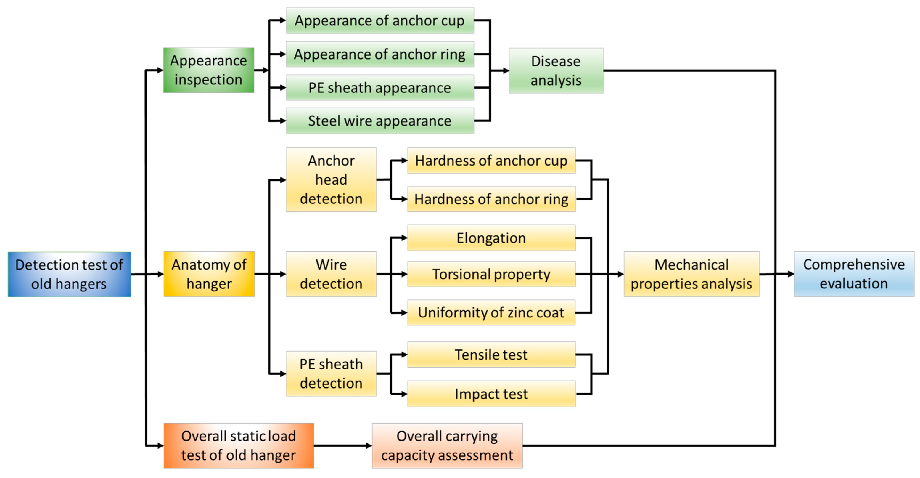
3.1. Hanger-Specific Test Content/Method

The detection methodology for hanger illness relied upon a visual examination approach, supplemented by the use of measurement instruments, marking tools, and camera techniques. A watercraft specifically designed for positioning was used to obtain the precise geographical coordinates of the lower anchor head. To ensure optimal lighting conditions, it is recommended to proceed with the following steps: Firstly, open the cover plate of the anchor box. Subsequently, inspect the lower anchor head for any water accumulation. Additionally, assess the aging condition of the grease within the anchor box. Furthermore, examine the corrosion status of both the inner and outer wire fasteners of the anchor head. Moreover, evaluate the deformation and corrosion conditions of the anchor pad plate.
Then, the corrosion condition of the pier head steel wire and the pier head nut can be assessed. Lastly, it is advised to document these observations through photography and written records. Upon reaching the upper anchor head position above the arch rib using a boarding truck, it is necessary to conduct an assessment for potential issues such as water seepage, white precipitation, breakage, cracks, and other ailments in the sealing anchor concrete. Additionally, measurements of crack length and width, as well as the area affected by the disease, should be taken. It is also important to document these findings through photography and written records.

3.2. Lower Anchor Head Detection

A total of 64 lower anchor heads of the bridge were tested. The results showed that the inner wall of the anchor box, anchor pad, pier head nut, inner and outer wire buckle of the anchor cup, and pier head steel wire were corroded to different degrees. A total of 35% of the anchor heads were seriously corroded, and nearly half of the anchor heads were soaked in water. The anti-corrosion grease filled in the anchor box was aged to varying degrees due to long-term soaking in water, and the anti-corrosion ability was reduced. The typical disease of the lower anchor head is shown in Figure 6.

3.3. Upper Anchor Head Detection

The inspection of the upper anchor head found that the sealing anchor concrete had circumferential peeling, local breakage, cracking, and white precipitation phenomenon. To further determine the water inside the hanger and identify the water source, the 2-13# hanger of the east span bridge, which was more seriously damaged, was selected, and the anchor sealing concrete was removed. The upper anchor box cover was cut and inspected, and it was found that the anchor box cover was not fully welded to the inner wall of the anchor box, and there were gaps at the welding edge. The disease condition of the upper anchor head is shown in Figure 7.

3.4. Hanger Disease Causes Analysis

3.4.1. Lower Anchor Head Disease Causes

A thorough examination was conducted on each component of the lower anchor head, involving disassembly for a detailed inspection. The lower anchor head exhibited varying degrees of corrosion in its anchor box, anchor pad, anchor cup, internal wire buckle, and external wire buckle. Nearly half of the lower anchor heads showed signs of water seepage during the disassembly process. Additionally, the anti-corrosion oil and grease applied to the anchor box aged to different extents. Based on a preliminary study, rainfall enters the lower anchor head via the gap in the steel casing of the higher anchor head. Consequently, rainwater collects in the lower anchor box without being promptly excluded, leading to the heightened corrosion of different components inside the lower anchor head.

3.4.2. Upper Anchor Head Disease Causes

The primary ailments affecting the top anchor head are the discoloration of the sealing anchor concrete and the occurrence of ring direction stripping. The observed whitening patterns were predominantly aligned with the ring direction and the direction of water flow. Additionally, there was significant peeling of the sealing anchor concrete and the surrounding arch rib concrete. Based on these findings, it can be inferred that rainwater infiltrated the upper anchor head through the arch rib, resulting in the whitening and deterioration of the sealing anchor concrete and the arch rib concrete. The occurrence of anchor concrete spalling and the presence of net-like fractures may potentially be attributed to temperature contraction cracks in the concrete, which are induced by the temperature variation between daytime and nighttime. During the examination, the upper anchor head of the east span of 2-13# hangers, which exhibited significant water seepage, was removed from the sealing anchor concrete through chiseling. Subsequently, the anchor box cover was inspected by opening the window, as depicted in Figure 8. The inspection revealed that the anchor box was heavily saturated with water and exhibited severe corrosion. This finding further confirmed the accuracy of the initial inference.

3.4.3. Investigation of Hanger Water Buildup

The results of the open box inspection of the hanger anchor head showed that the main reasons for the severe water accumulation inside the hanger were as follows:
i.
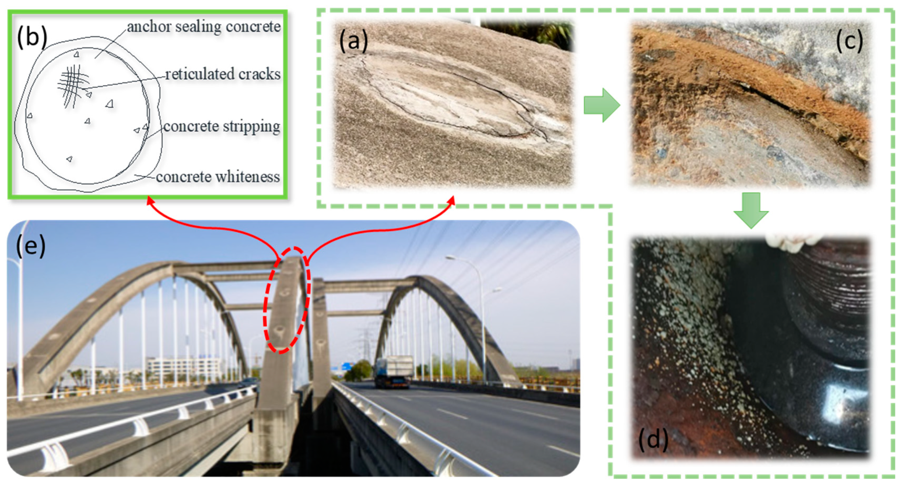
Rainwater penetrated through cracks in the sealing anchor concrete, entered through the gap in the upper anchor box cover, and then flowed into the lower-anchor box along the inner wall of the outer steel pipe. The distribution of the primary diseases on the anchor head of the bridge and the water flow lines are shown in Figure 9b.
ii.
The structure of the bridging hanger is important. The finished cable has a seamless steel pipe on the outside, and the wet air enters the inside of the steel pipe when the temperature of the inner wall of the steel pipe is lower than the dew point temperature of the wet air. Furthermore, condensation will form in the pipe, and because the steel pipe is closed, the water does not easily evaporate.
iii.
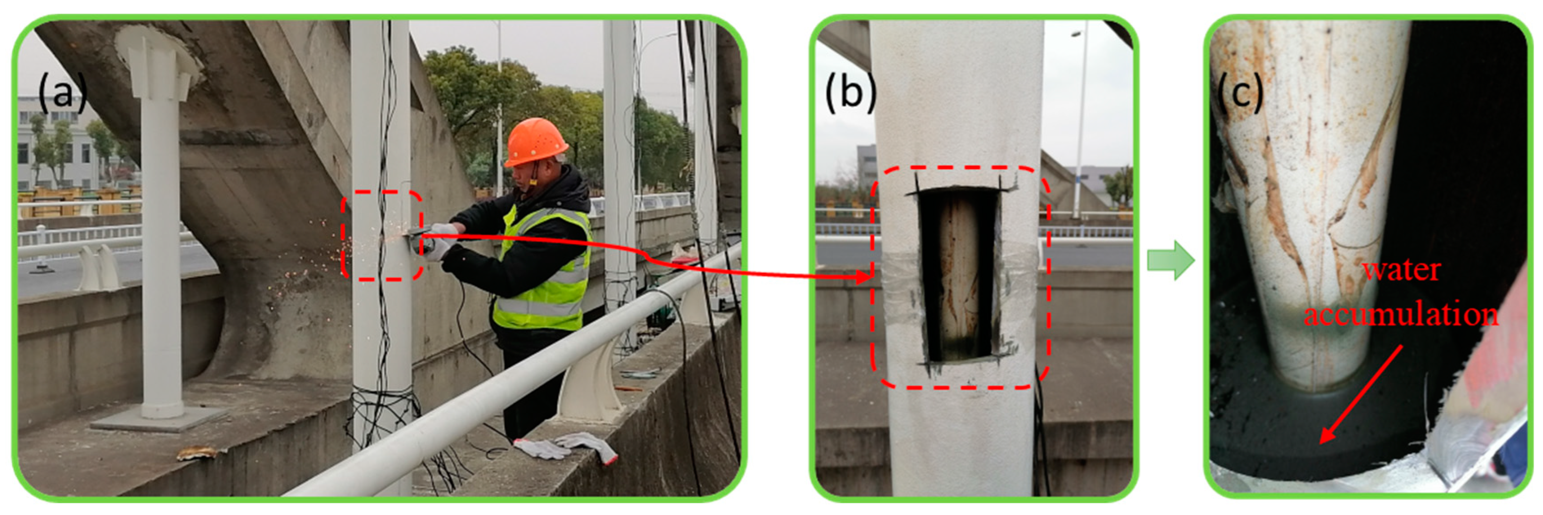
In order to facilitate a description of the disease degree of the anchor head, according to the ‘Technical Condition Assessment Standard for Highway Bridges’ (JTG/TH 21-2011) [20], the anchor head corrosion can be divided into two grades according to the corrosion area, namely, slight corrosion (cumulative corrosion area ≤ 3% of the component area) and severe corrosion (cumulative corrosion area > 10% of the component area). The water accumulation in the anchor head is divided into two grades according to the amount of water, namely slight water accumulation (there is a small amount of water or water vapor in the anchor head, and the air humidity is large) and serious water accumulation (the water accumulation in the anchor head is very serious or the air is very humid, and the anchor head is seriously corroded). The distribution of anchor head disease is shown in Figure 9a. As the lower anchor box is filled with anti-corrosion grease, the water flow cannot be discharged, resulting in rainwater and condensation gathering inside the lower anchor box and the outer steel pipe and causing the anti-corrosion grease to age and fail, which, in turn, causes different degrees of rusting of the anchor head components. The water accumulation in the outer steel pipe is shown in Figure 10.

4. Analysis of Old Hanger Test Detection

The assessment of the operational state of in-service hangers is challenging due to the insufficient testing that has been confucted. Therefore, it is imperative to conduct extensive experimental testing and research on the replaced hangers affected by the disease. This will enable a thorough evaluation of the operational status of the hangers and facilitate the provision of maintenance recommendations for future reference.
Under careful consideration of the hanger force and disease, hanger 2-13# of the east width bridge, with the more severe condition, was finally selected for replacement, and the old hanger that was removed was subjected to a detailed appearance inspection as well as indoor experiments to assess the overall operating performance of the hanger. The test route of the old hanger is shown in Figure 11.
First, a careful appearance examination focused on the disease status of each component of the old hanger, including the corrosion of the anchor cups, anchor rings, sealing cylinders, and PE sheath, and the source of the illness. It was also necessary to conduct a total static load test on the disassembled old hanger to precisely verify its bearing capacity. After disassembling the old hanger, steel wire corrosion, and steel wire, anchor cup, anchor ring, and PE sheath mechanical qualities were tested. After reviewing the unique test findings and mechanical qualities of the old hanger, its performance was assessed.

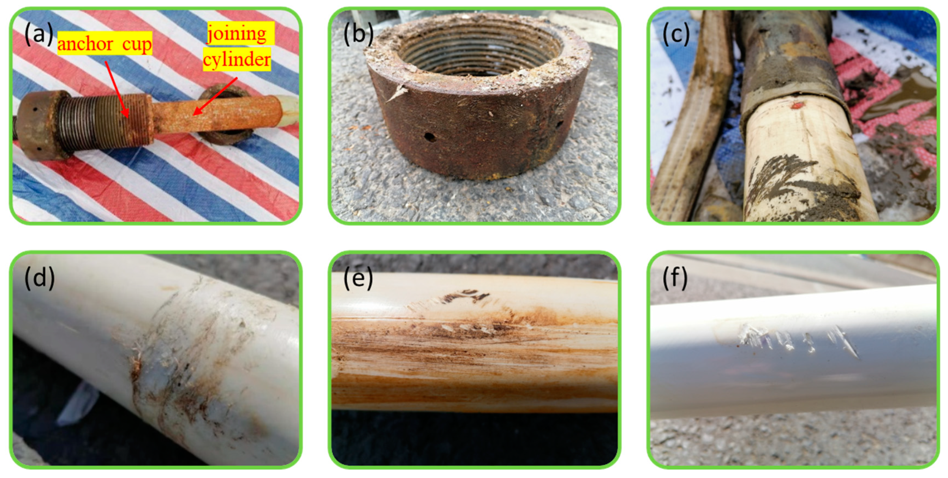
4.1. Hanger Appearance Inspection

The original hanger’s anchor cup, anchor ring, and connecting cylinder were placed in a humid environment for a long time and had varied degrees of corrosion, with the outside thread of the anchor cup corroding the most. Anchor corrosion reduces the hanger’s lifespan, cable force adjustment, and replacement. A visual examination found that the heat-shrink sleeve-sealing between the connecting cylinder and the cable body was damaged, and the PE sheath had several transverse and longitudinal scratches, water buildup, and no penetrating fracture. Figure 12 illustrates the old hanger’s visual examination.
As the hanger’s PE sheath is directly exposed to the atmosphere for years, rain, wind, ultraviolet radiation, and the accidental impact of the joint role of the disease cause cracks, scratches, voids, etc. In this hanger, the jacket steel pipe protects the PE jacket from UV radiation and accidental impact. Rainwater pooled in the outer jacket steel pipe, submerging the lower end of the hanger PE sheath for a long time. During the construction of the hanger, the PE sheath is easy to cut with the steel pipe’s inner wall, increasing the danger of damage.
A study found that the following causes promote PE sheath surface damage:
i.
Factory faults. Due to the complexity of hanger manufacture, damage cracking, hanger installation construction, and neglect during construction directly damage the bridge hanger after installation.
ii.
Human factors. Transportation, storage, coil, unfolding, towing, lifting, traction, anchoring, tensioning, and adjustment are all complicated. The PE jacket hanger, made of flexible polymer, is easily damaged during transportation, hanging, tensioning, and other processes.
iii.
Live load affects. The function of automobiles, pedestrians, and other living loads causes hanger stress changes, hanger and beam vibration increases, and hanger elongation, which causes PE material fatigue, cracking, and protection system failure.

4.2. Hanger Overall Static Load Test

The demolished old hanger is 13,960 mm long and 65 mm in diameter, and the nominal breaking force Pb is 2787 kN. To accurately reflect the operating performance of the old hanger, the overall static load test is carried out. The 2YBZ2-80 oil pump and YDC6500-1000 jack were used to load this. Each stage’s hanger length change was measured after 5 min loading, from 0.1Pb to 0.1Pb per stage, and the loading rate was no more than 100 MPa/min. When loaded to 0.8Pb after 30 min loading, loading continued, with each level at 0.05 Pb. After 5 min, each stage’s hanger length changes, record tensile load, and sample elongation were measured.
The results show that when the test force is loaded to 2647.6 kN, the static load efficiency coefficient of the hanger is ≥0.95, which meets the requirements of the specification [18]. The total strain of the hanger in this static load test is 2.8%, which meets the specification requirements of ultimate elongation with a strain greater than 2% [18]. The overall bearing capacity of the hanger is not significantly weakened. The overall static load test of the hanger is shown in Figure 13.

4.3. Anchor Head Detection

The method used to measure the hardness of the anchor is to press the diamond indenter vertically into the material’s surface to produce a dent for testing under the specified external load. According to the depth of the dent, after the load is released, the Rockwell hardness can be calculated using the Rockwell hardness calculation formula, as shown in Equation (1). The Rockwell hardness value is displayed on the dial of the hardness tester, as follows:
H R = ( K H ) / C
where HR is Rockwell hardness value; K is constant, K = 0.2 mm when testing with diamond cone indenter, K = 0.26 mm when testing with steel ball indenter; H is indentation depth after load release; C is residual indentation depth increment of 0.002 mm.
As shown in Figure 14, the hardness of the anchor cup and anchor ring was measured in the lab using two measurement zones and three tests per zone. The anchor cup and anchor ring hardnesses at each test point are less than the standard value [18], suggesting low hardness due to long-term corrosion and alternating loads. The hanger’s load-carrying capacity is not significantly weakened by the overall static load test, but as the anchor end corrodes, its anchorage performance will be threatened, which could lead to bridge structure safety issues like deformation, cracks, or destabilization and collapse.
In engineering applications, galvanization, chromium plating, epoxy resin-spraying, etc., may improve anchoring corrosion resistance. At the same time, one should avoid installing anchorages in dry and wet environments and pay attention to drainage system settings to limit environmental corrosion. Furthermore, it is crucial to constantly inspect the anchorage’s surface and detect early corrosion, before removing it using an antirust agent, and replacing damaged pieces.

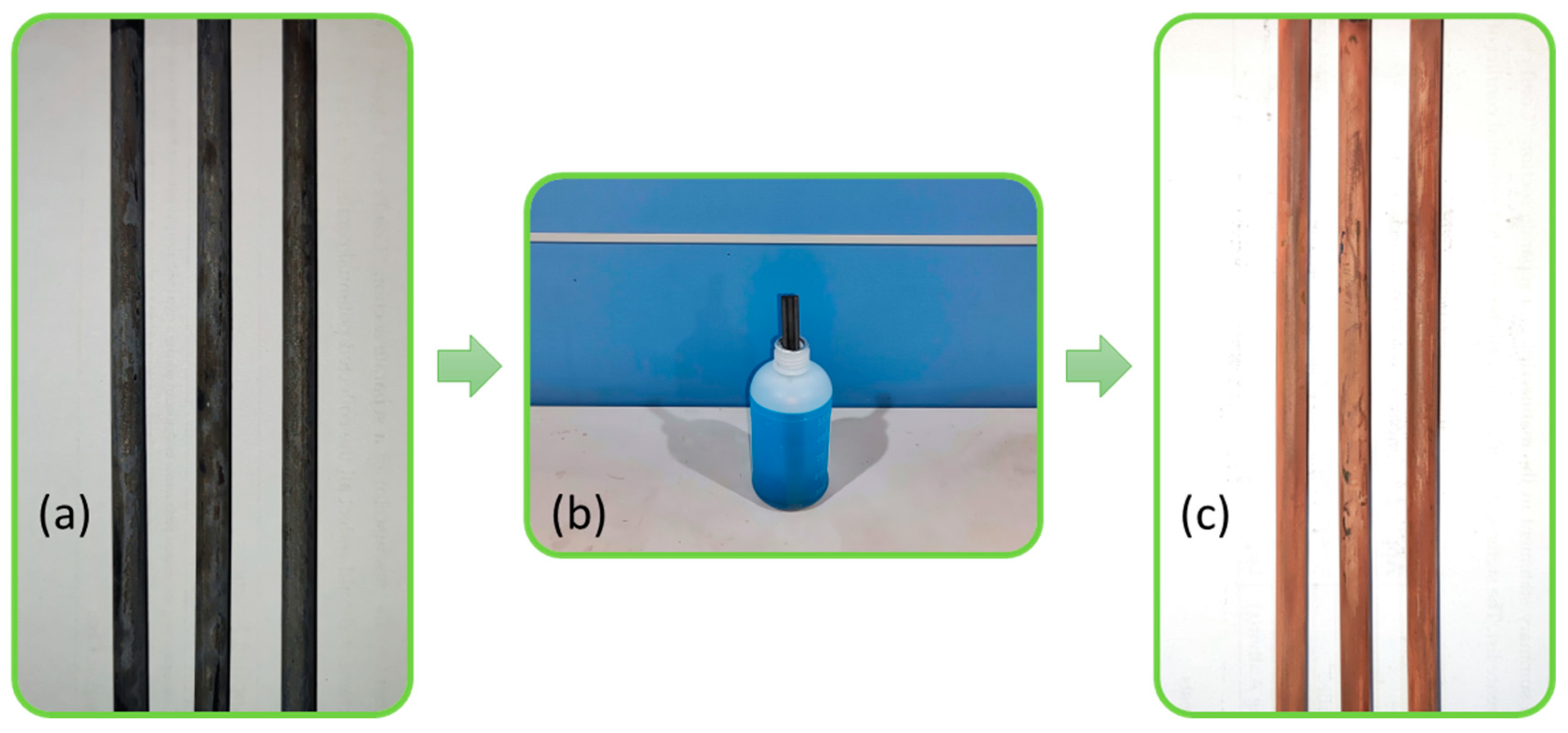
4.4. Steel Wire Detection

4.4.1. Tensile Performance

A representative sample with a length of 1200 mm was selected from the upper, middle, and lower parts of the hanger to carry out the tensile property test on steel wire. An electronic tensile testing machine stretched the sample until it was broken. The material’s mechanical properties were measured, including tensile strength and elongation after fracture. The experiment was conducted at a room temperature of 10–35 °C. The test results are shown in Figure 15. Established research shows that corrosion weakens steel wire cross-sections, reducing load-bearing ability. Pore corrosion increases surface roughness, decreasing final elongation. See Figure 15 for the surface corrosion of the steel wire in the old hanger. When the corrosion is mild, the steel wire shows apparent necking shrinkage before fracture and a cup-shaped fracture with radial stripes in the middle. The tensile test results of the wire showed that the minimum value of tensile strength was 1705 MPa, the minimum value of the modulus of elasticity was 1.92 × 10⁵ MPa, and the minimum value of elongation after break was 4% in all three specimens, all of which followed the specification [18], which indicated that the tensile properties of the wire did not significantly deteriorate.

4.4.2. Torsional Performance

One specimen with a length of 250 mm was selected from the hanger’s upper, middle, and lower parts to conduct the steel wire torsion test. The specimen was placed in a flat fixture of the testing machine, and the rotating clamp was rotated at a constant speed. The torsion speed was no more than 0.25 rad/s, and the specimen was twisted until fracture. The number of rotation cycles was recorded. The test results are shown in Table 1. As can be seen from the table, the maximum number of times the specimen was twisted was five, which could not meet the specification requirements [18], indicating that the steel wire torsional performance decay is extensive. The primary factor contributing to the degradation of torsional properties in the steel wire is the prolonged usage of the hanger over 15 years. The steel wire is susceptible to fatigue when subjected to high dynamic loads, resulting in a reduction in its elasticity. This reduction in elasticity leads to a weakening of the torsional properties exhibited by the steel wire.

4.4.3. Uniformity of Galvanized Layer

The integrity of the galvanized layer of steel wire directly affects the chance of occurrence and the rate of the development of rust on the wire. For this reason, the resistance of the steel wire’s galvanized layer to copper sulfate must be tested [21]. The test photo is shown in Figure 16. Within the specified time, the galvanized steel wire sample was immersed in copper sulfate solution, either once or several times continuously, and the replacement reaction was carried out to gradually dissolve the zinc layer. Moreover, defects were exposed on the surface to determine the uniformity of the zinc coating. Three wires were randomly selected, and the test results are shown in Table 2. As can be seen from the table, the maximum number of times the specimen wire resisted copper sulfate was two, indicating that the galvanized layer of the wire was significantly weakened and the protective effect on the inner layer of the wire was attenuated, which could not meet the specification requirements [18].

4.5. PE Sheath Detection

4.5.1. Tensile Performance

The tensile properties of the PE sheath of the hanger directly reflect the degree of protection the PE sheath confers to the internal steel wire [21]. The PE sheath, after being immersed in water at the lower anchor head for a long time, was selected as the test material, hot-melted and poured, and finally, three sets of tensile specimens were made. The appearance and size of the sample are shown in Figure 17a,b.
An electronic tensile testing machine carried out a tensile test of the specimen to test the tensile fracture stress. The tensile performance test results are shown in Table 3. As can be seen from the table, the hanger PE shows a certain degree of the aging phenomenon; the tensile properties are severely attenuated and can no longer meet the specification requirements [18].

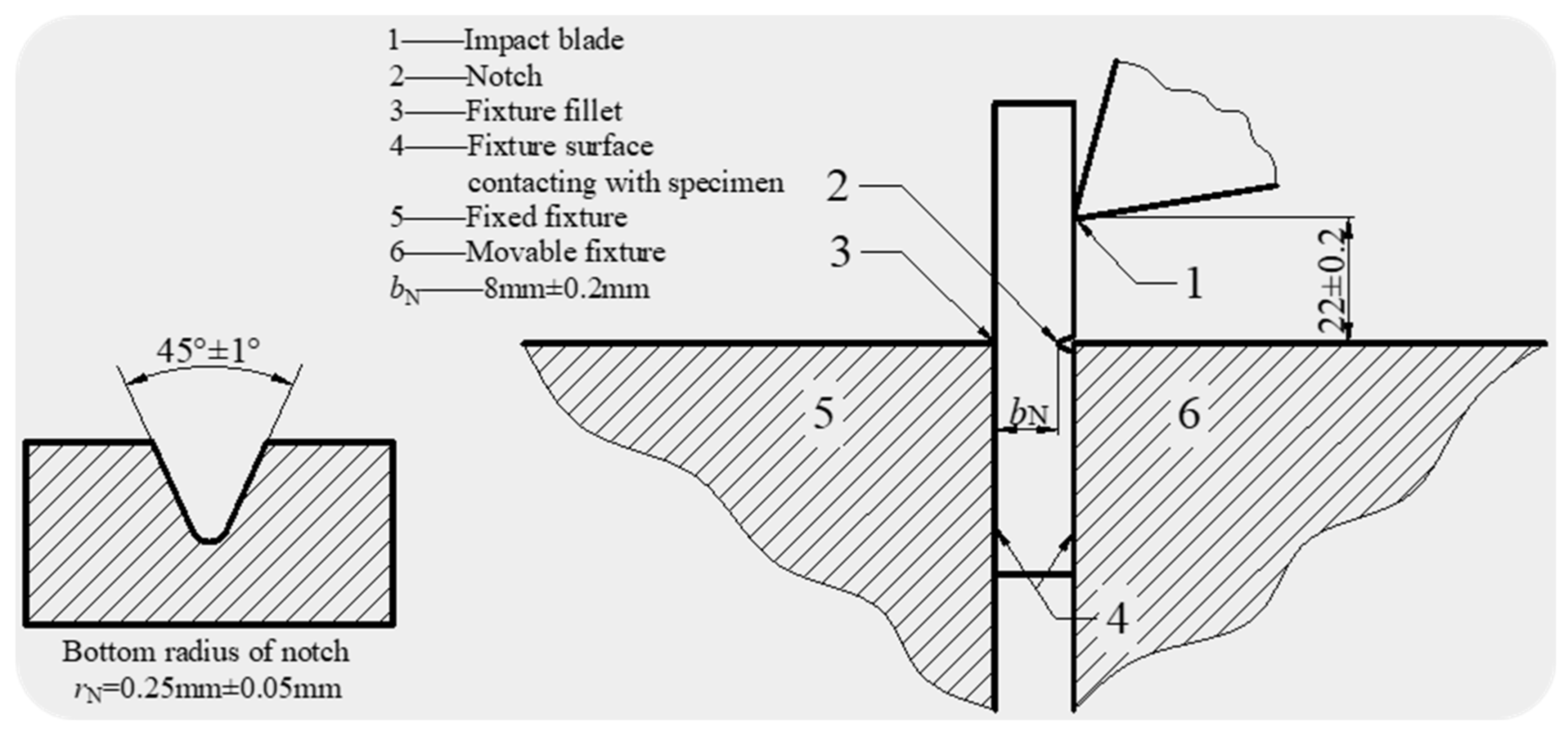
4.5.2. Impact Strength

The PE sheath at the lower anchor head was reselected as the raw test material, and three sets of impact specimens were prepared. Sample length L = 80 mm ± 2 mm; width b = 10 mm ± 0.2 mm; thickness h = 4 mm ± 0.2 mm. The notched specimens should be prepared according to the ISO 2818-1994 [22] mechanical processing method, as shown in Figure 18. As seen in Table 4, there is a certain degree of post-aging embrittlement in the PE sheath of the hanger, which can no longer meet the specification requirements [18].

4.6. Comprehensive Evaluation and Analysis

Special tests of the whole bridge hanger indicated that, after 15 years of operation, all 64 hangers had varying degrees of illness, particularly anchor head corrosion, water seepage, and anticorrosion grease aging. The JTG/T H21-2011 Standard for Evaluation of Technical Condition of Highway Bridges [20] classifies hanger component disease levels from light to heavy, with grade 1 being the lightest. As shown in Figure 19, 23.4% of the anchor head threads of all 64 hangers on the bridge have corrosion extending to the nut, where the oxide skin is partially peeled off or can be scraped off, and a few rust pits exist on the surface (the disease grade is 3); 48.4% of anchor heads have water seepage, 37.5% of which have serious water accumulation or excess water vapor, and the air is humid (disease level 3); 56.3% of anticorrosion grease has different degrees of aging, 43.8% of which show serious volatilization, large caking, and mildew.
In the old hanger test results, the hanger as a whole and the tensile mechanical properties of a single steel wire are not significantly weakened, but the single steel wire torsion resistance and galvanized layer of copper sulfate-resistant performance are significantly weakened and cannot meet the use requirements. The extensibility and impact resistance of PE sheath material decline with age, making it unsuitable for hanger steel-wire sealing and protection. After a complete inspection, bridge hanger illness is mostly caused by non-stress faults. The major cause is the natural environment’s erosion, age, and a faulty original structure. Timely maintenance treatment is needed since these illnesses would reduce building durability and service life.
According to a statistical analysis of tied-arch bridge-hanger replacement instances [23], a tiny portion of them are due to substantial damage from car contact or seismic stress, which compromises bridge safety. Most hangers are damaged by natural corrosion and traffic stresses, resulting in hanger steel-wire corrosion and fatigue fracture, anchor head corrosion and water buildup, and a decline in anchoring effectiveness. Figure 20 presents 86 example bridges, showing that hangers last 3–23 years, averaging 14 years. The hanger’s service life is much shorter than the bridge’s designed service life, with 44.2% lasing between 10 and 15 years, 19.8% between 15 and 20 years, and 18.8% over 20 years. This report describes a 15-year-old bridge whose hangers have outlasted comparable bridges. Given the bridge’s construction, the hanger disease detection and mechanical properties obtained from comprehensive analysis test results suggest that seriously diseased hangers should be replaced as soon as possible to ensure bridge safety.

5. Conclusions

The special inspection of a tied-arch bridge hanger summarized the type and distribution law of the anchor head damage, analyzed the causes of the damage and, combined with the mechanical performance test results of the old hanger, proposed a performance evaluation method for the working performance of remaining in-service hangers, and conducted a systematic evaluation of the operating performance of the in-service hanger of the case bridge. The following findings and recommendations were obtained:
(1)
For hangers with outer steel pipe protection, precipitation can enter the lower-anchor box via the upper anchor box along the crevice between the hanger and the outer steel pipe; therefore, the effectiveness of the upper anchor box’s waterproofing system must be prioritized. Because the lower anchor head of the hanger is filled with anti-corrosion grease and there is no effective water discharge device, precipitation and condensate collect in the lower anchor box and outer steel conduit, causing the anti-corrosion grease to fail and the anchor head to corrode. In order to ensure that the water in the lower anchor head can be drained on time, the lower anchor box should be equipped with additional drainage openings.
(2)
The hangers in this type of bridge are protected by the outer steel pipe, which effectively shields the PE sheathing from ultraviolet radiation and other environmental factors. However, the inspection results of the appearance of the old hanger indicate that the PE sheathing has numerous scuffs and scratches, which will reduce its durability and increase its risk of cracking. Necessary protective measures should be taken during the construction of the hanger to avoid rubbing between the PE sheath and the inner wall of the steel pipe. In addition, the protective steel pipe also makes the daily maintenance of the hanger more difficult.
(3)
According to the mechanical property test results of the old hanger, the tensile mechanical properties of the whole and single steel wires are not significantly weakened and still meet the specification requirements. However, the torsion resistance of the single steel wire and the copper sulfate resistance of the galvanized layer is significantly weakened. It cannot meet the use requirements, the PE sheath is aging, and the impact resistance is reduced (embrittlement) and does not meet the use requirements.
(4)
With advancements in hanger construction technology, the widespread use of novel materials, and the enhancement of testing methodologies, it is advisable to include high-tech approaches to enhance the non-destructive testing of hangers during routine and periodic inspections. In the event that hanger replacement becomes essential, it is recommended to integrate the use of novel materials and advanced technologies in order to enhance the longevity of the hanger.

Author Contributions

Conceptualization, L.Z. and L.C.; methodology, L.C.; software, T.C., L.C. and Z.L.; validation, X.H. (Xiaolun Hu) and X.H. (Xiaoming Huang); formal analysis, L.C. and Z.L.; resources, L.C.; data curation, X.H. (Xiaolun Hu) and X.H. (Xiaoming Huang); writing—original draft preparation, L.Z. and T.C.; writing—review and editing, L.Z., T.C., L.C., Z.L., X.H. (Xiaolun Hu) and X.H. (Xiaoming Huang); visualization, Z.L. and X.H. (Xiaoming Huang); supervision, L.C.; project administration, X.H. (Xiaolun Hu) and X.H. (Xiaoming Huang); funding acquisition, L.C. All authors have read and agreed to the published version of the manuscript.

Funding

The work in this paper was supported by the 2023 Yangzhou Key Development Program Program (Social Development) Project Grant No. YZ2023077, Natural Science Foundation of Jiangsu Province of China under Grant No. BK20200705, and the Key Technologies Research and Development Program (CN) under Grant No. 2021YFB2600600.

Institutional Review Board Statement

Not applicable.

Informed Consent Statement

Not applicable.

Data Availability Statement

All relevant data are included within the paper.

Acknowledgments

Author Chen, L thank the 2018 Jiangsu Provincial Government Scholarship Program (No. 228) for the bearing of his visit to the University of California, Los Angeles.

Conflicts of Interest

Author Lingkun Chen was employed by the company Transportation Science Institute of Nanjing University of Technology (Chuzhou) Co., Ltd., the remaining authors declare that the research was conducted in the absence of any commercial or financial relationships that could be construed as a potential conflict of interest.

References

  1. Zheng, M. Experimental Study on Cables Performance of Bridges in Service. Ph.D. Thesis, Chongqing Jiaotong University, Chongqing, China, 2015. [Google Scholar]
  2. Wu, W.; Wang, H.; Zhu, Y.; Yu, J.; Zhao, H.; Zhang, H. New hanger design approach of tied-arch bridge to enhance its robustness. KSCE J. Civ. Eng. 2018, 22, 4547–4554. [Google Scholar] [CrossRef]
  3. Liu, Z.; Guo, T.; Hebdon, M.H.; Zhang, Z. Corrosion fatigue analysis and reliability assessment of short suspenders in suspension and arch bridges. J. Perform. Constr. Facil. 2018, 32, 04018060. [Google Scholar] [CrossRef]
  4. Song, Y.; Ding, Y.; Zhong, W.; Zhao, H. Reliable fatigue-life assessment of short steel hanger in a rigid tied arch bridge integrating multiple factors. J. Perform. Constr. Facil. 2018, 32, 04018038. [Google Scholar] [CrossRef]
  5. Zhao, H.; Ding, Y.; An, Y.; Li, A.Q. Transverse dynamic mechanical behavior of hangers in the rigid tied-arch bridge under train loads. J. Perform. Constr. Facil. 2016, 31, 04016072. [Google Scholar] [CrossRef]
  6. Wu, G.; Qiu, W. Effect of load cases and hanger-loss scenarios on dynamic responses of the self-anchored suspension bridge to abrupt rupture of hangers. J. Perform. Constr. Facil. 2020, 34, 04020081. [Google Scholar] [CrossRef]
  7. Fan, B.; Wang, S.; Chen, B. Dynamic effect of tie-Bar failure on through tied arch bridge. J. Perform. Constr. Facil. 2020, 34, 04020089. [Google Scholar] [CrossRef]
  8. Nakamura, S.; Miyachi, K. Ultimate strength and chain-reaction failure of hangers in tied-arch bridges. Struct. Eng. Int. 2020, 31, 136–146. [Google Scholar] [CrossRef]
  9. Li, H.; Lan, C.M.; Ju, Y.; Li, D.S. Experimental and numerical study of the fatigue properties of corroded parallel wire cables. J. Bridge Eng. 2012, 17, 211–220. [Google Scholar] [CrossRef]
  10. Zheng, X.; Xie, X.; Li, X. Experimental study and residual performance evaluation of corroded high-tensile steel wires. J. Bridge Eng. 2017, 22, 04017091. [Google Scholar] [CrossRef]
  11. Liu, Z.; Guo, T.; Han, D.; Li, A. Experimental study on corrosion-fretting fatigue behavior of bridge cable wires. J. Bridge Eng. 2020, 25, 04020104. [Google Scholar] [CrossRef]
  12. Chen, Z.; Chen, H.; Liu, H.; Yang, S. Corrosion behavior of different cables of large-span building structures in different environments. J. Mater. Civ. Eng. 2020, 32, 04020345. [Google Scholar] [CrossRef]
  13. Li, S.; Xu, Y.; Li, H.; Guan, X. Uniform and pitting corrosion modeling for high-strength bridge wires. J. Bridge Eng. 2014, 19, 04014025. [Google Scholar] [CrossRef]
  14. Karanci, E.; Betti, R. Modeling corrosion in suspension bridge main cables. I: Annual corrosion rate. J. Bridge Eng. 2018, 23, 04018025. [Google Scholar] [CrossRef]
  15. Wu, W. Disease characteristics and detection indexes of suspender anchor head of flexible suspender arch bridge. Urban Roads Bridges Flood Control 2016, 8, 264–267, 298. [Google Scholar]
  16. Luo, Y. Degradation analysis and pre-maintenance of cable-stayed bridge cold-cast pier head anchor. Urban Roads Bridges Flood Control 2017, 5, 211–214, 20. [Google Scholar]
  17. Wang, C.; Liu, Q. Longdi Bridge suspender disease analysis and maintenance reinforcement scheme research. J. China Foreign Highw. 2010, 30, 169–172. [Google Scholar]
  18. GB/T 18365-2018; Hot-Extruded PE Protection Paralleled High Strength Wire Cable for Cable-Stayed Bridge. Ministry of Transport of the People’s Republic of China: Beijing, China, 2018.
  19. GB/T 17101-2019; Hot-Dip Zinc or Zinc-Aluminium Coated Steel Wires for Bridge Cables. China Iron and Steel Industry Association: Beijing, China, 2019.
  20. JTG/T H21-2011; Technical Condition Assessment Standards for Highway Bridges. People’s Transportation Publishing House: Beijing, China, 2011.
  21. Wu, Z.; Sheng, H.; Zheng, M.; Wang, W.; Chen, J. Old Cable-stayed bridge test detection and Residual life assessment. J. China Foreign Highw. 2015, 35, 103–108. [Google Scholar]
  22. ISO 2818-1994; Plastics-Preparation of Test Specimens by Machining. International Organization for Standardization: Geneva, Switzerland, 1994.
  23. Su, J.; Zhang, J.; Zhou, J.; Hu, C.; Zheng, Y. Fatigue life assessment of suspenders in tied-arch bridges under random traffic loads and environmental corrosion. Int. J. Civ. Eng. 2023, 21, 523–540. [Google Scholar]
Figure 1. Typical cable-supported bridges their components: (a) the suspension bridge and its components, (b) the tied-arch bridge and its components, (c) the cable-stayed bridge and its components.
Applsci 13 11070 g001
Figure 2. Corrosion of the steel strand and anchor end of the Jinsha River Bridge hanger: (a) actual view of the bridge wreckage, (b) lower anchor end of the hanger, (c) corrosion fracture of hanger wire.
Applsci 13 11070 g002
Figure 3. Fracture of the short hanger of the rail bridge: (a) LM2 short hanger, (b) fractured LM2, (c) upper fracture surface, and (d) lower fracture surface.
Applsci 13 11070 g003
Figure 4. Typical cable diseases of a cable-stayed bridge: (a) PE sheath cracking, (b) steel wire corrosion, (c) anchor cup corrosion.
Applsci 13 11070 g004
Figure 5. Tied-arch bridge in this study: (a) structure of the hanger, (b) elevation of the bridge (unit: cm), (c) disease of the lower anchor head: corrosion of lower anchor head components, and (d) disease of the lower anchor head: water seepage in the lower anchor head.
Applsci 13 11070 g005
Figure 6. Typical diseases of lower anchor head: (a) anchor head water seepage, (b) corrosion of lower anchor head, and (c) anticorrosive oil aging in the lower anchor box.
Applsci 13 11070 g006
Figure 7. A disease of the upper anchor head: (a) sealed anchor concrete, (b) diagram of sealing anchor concrete disease, (c) upper anchor box cover plate welding defects, (d) corrosion of upper anchor head and water accumulation, and (e) front view of the bridge.
Applsci 13 11070 g007
Figure 8. Window-opening detection of upper anchor box cover plate.
Applsci 13 11070 g008
Figure 9. Waterlogged disease inside the hanger: (a) disease distribution of anchor head, and (b) water flow inside the hanger.
Applsci 13 11070 g009
Figure 10. Detection of internal water accumulation in steel pipe: (a) pipe cutting, (b) steel pipe window opening, and (c) water inside the steel pipe.
Applsci 13 11070 g010
Figure 11. Detection road map of the hanger test.
Applsci 13 11070 g011
Figure 12. Old hanger appearance detection: (a) corrosion of anchor cup and sealing cylinder, (b) corrosion of anchor ring, (c) damage to heat-shrinkable casing, and (df) PE sheath damage.
Applsci 13 11070 g012
Figure 13. Static load test of the hanger: (a) tensioning table, (b) anchor end, (c) oil pressure gauge, and (d) tension display.
Applsci 13 11070 g013
Figure 14. Hardness test results of anchor cup and anchor ring.
Applsci 13 11070 g014
Figure 15. Steel wire tensile test.
Applsci 13 11070 g015
Figure 16. Copper sulfate resistance test of steel-wire-galvanized layer: (a) experiment samples, (b) copper–sulfuric acid solution, and (c) copper exposed after sample test.
Applsci 13 11070 g016
Figure 17. PE sheath tensile test: (a) PE sheath sample size, (b) tensile testing machine.
Applsci 13 11070 g017
Figure 18. Impact test schematic.
Applsci 13 11070 g018
Figure 19. Statistics of service life of hangers: (a) anchor head thread corrosion assessment results, (b) anchor head water penetration assessment results, and (c) preservation grease aging assessment results.
Applsci 13 11070 g019
Figure 20. Statistics of hanger service life.
Applsci 13 11070 g020
Table 1. Test results of the torsional performance of steel wire.
Testing ItemsStandard Requirements [18]Test Results (Times)Single-Item Judgment
Torsional PerformanceNumber of times ≥ 814Failure
25
34
Table 2. Galvanized layer uniformity test results.
Testing ItemsStandard Requirements [18]Test Results (Times)Single-Item Judgment
Uniformity of galvanized layerNumber of times ≥ 412Failure
20
31
Table 3. Test results of tensile properties of PE sheath.
Testing ItemsStandard Requirements [18]Test Results (MPa)Single-Item Judgment
PE sheath tensile properties≥25 MPa112.01Failure
26.95
34.33
Table 4. The impact strength test results of PE sheath.
Testing ItemsStandard Requirements [18]Test Results (KJ/m2)Single-Item Judgment
PE sheath impact strength≥50 KJ/m2123Failure
221
326
Disclaimer/Publisher’s Note: The statements, opinions and data contained in all publications are solely those of the individual author(s) and contributor(s) and not of MDPI and/or the editor(s). MDPI and/or the editor(s) disclaim responsibility for any injury to people or property resulting from any ideas, methods, instructions or products referred to in the content.

