1. Introduction
Vibration isolation is an effective way to reduce vibration transmission from rotary mechanical equipment, as well as an important means of reducing vibration and noise [
1]. Double-layered vibration isolation [
2], floating raft vibration isolation [
3] and other passive vibration isolation methods play an important role in middle- and high-frequency bands. Michał [
4] discussed minimizing the effect of external mechanical vibration on hydraulic valves in different military hydraulic drive systems by introducing materials with known stiffness and damping characteristics to reduce the vibration on the valve casing, but such materials fail to meet the requirements for the low-frequency vibration isolation of rotary mechanical equipment. Active vibration isolation effectively suppresses low-frequency vibrations with an additional force source [
5]. However, there are problems, such as large energy consumption and unsatisfactory bearing capacity. Active–passive hybrid vibration isolation technology combines the technical advantages of active and passive vibration isolation. Therefore, it has wider application prospects. Currently, further research is still required to achieve an effective combination of active–passive hybrid vibration isolation technology in order to realize a high output force, large bearing capacity, low power consumption and impact resistance [
6,
7,
8].
Li [
9] established a magnetic field analytical model of a non-equal-size Halbach array based on the equivalent magnetic charge method and the principle of field strength superposition. This magnetic field analytical model improves the linearity of the output force and reduces the power loss, but it fails to meet the requirements for impact resistance and large bearing capacity. Zhang [
10] designed a hybrid vibration isolation system combining an active piezo stack-based actuator and passive rubber-based isolator, and it has a compact structure with high reliability, reducing the resonance peak, but the bearing capacity is unsatisfactory. Zhang [
11] designed a new electromagnetic actuator based on Maxwell’s normal stress, which improves the low-frequency vibration isolation effect under the static stiffness and realizes the vibration isolation in a wider frequency band by combining the passive vibration isolation device, but the reliability under dynamic working conditions has not been verified. Meng [
12], Xu [
13] and Mbayed [
14], respectively, proposed a new magnetic circuit topology that integrated the magnetic flux leakage effect, edge effect and nonlinear magnetic permeability, which improved the output force of the actuator but failed to consider power consumption and heat generation. Wang [
15] embedded the fluid damping into the electromagnetic actuator, which can effectively isolate tiny vibrations in the range of 5–200 Hz, but it failed to meet the requirements for vibration isolation requiring a large output force. Fu [
16] designed a hybrid vibration isolation system combining a magnetorheological semi-active vibration isolator and a piezoelectric stack actuator; meanwhile, the author also designed an active semi-active switch according to the excitation input. The combination of the semi-active piezoelectric actuator and the changeover switch effectively attenuates the full-band vibration, but the output force response is slow, and the displacement of the mover is large, which is not conducive to the stability of the active control. Henderson [
17] proposed a new electro–hydraulic hybrid vibration isolation system electro-hydrostatic actuator (EHA), which consists of the brushless DC motor and the bidirectional gear pump. EHA, featured in low natural frequency and low power consumption, is applied to the vibration control between helicopter fuselage and rotor. However, the problem of oil leakage occurs and EHA’s performance is greatly affected by the temperature, resulting in affected accuracy of control. Wang [
18] integrated the differential magnetic suspension actuator and the spiral spring into the active–passive hybrid vibration isolation system. The spiral spring bears the load, and the magnetic suspension actuator performs the active control. A 9–24 dB control effect was achieved on the 5–15 Hz line spectrum, but the spiral spring was plastically deformed with stiffness changes, resulting in insufficient reliability.
In addition, some scholars improved the performance of hybrid vibration isolation systems in conjunction with the active control algorithms [
19,
20,
21]. Targeting the problem of the operating failure of the electromagnetic actuators in the case of strong disturbances or shocks, Zhang [
22] analyzed the output of an electromagnetic actuator and optimized the control algorithm of the input current signals, and the shock resistance improved effectively. Li [
23] designed an integrated vibration isolator by combining an air spring and a magnetic suspension actuator and applying it to the vibration isolation system of a diesel generator set by combining the multifrequency narrow-band Fx-Newton time–frequency domain algorithm. However, the stator of the magnetic suspension actuator is prone to contact failure, and the air spring requires great dynamic stiffness of the rubber, resulting in a short reliability cycle of the system. Yang [
24] intensively studied the active vibration isolation of a nonlinear isolator with the elastic boundary in the broadband and proposed a new feedback control algorithm to control the input current of the actuator, but the broadband vibration transmissibility was obviously reduced. Hu [
25] designed a multi-objective particle swarm robust hybrid control algorithm based on adaptive filter compensation aiming at the influence of the nonlinear characteristics of the electromagnetic active suspension isolator on the performance of the control system. The results showed that the hybrid controller can restrain the control force within the unsaturated range and eliminate the influence of the nonlinear characteristics of the actuators on the active suspension, but the control algorithm is not universal. Basaran [
26] used two opposite electromagnets to determine the instantaneous displacement of the mass of the isolator and provided current signals to the coil through adaptive feedback control. Such an arrangement is suitable for damping systems, but the structural stability is poor.
In summary, the current work focused on increasing the load capacity, output and improving the impact resistance. This paper proposes a magnetorheological electromagnetic active–passive hybrid vibration isolation system that combines an electromagnetic active vibration isolator, rubber passive vibration isolator and magnetorheological damper in parallel. The electromagnetic actuator adopts a floating design with an output shaft designed with a sliding bearing that directly transfers the lateral force of the upper load to the housing. To reduce eddy current losses, both the mover yoke and the stator yoke were designed with radial grooves. Moreover, an ASFXLMS algorithm is proposed. A suppression factor is introduced based on the FXLMS algorithm to adjust the update of the control weight coefficient to limit the amplitude to within the actuator saturation region.
The remainder of this paper is divided into five sections.
Section 2 introduces the structure and design of the hybrid vibration isolation system.
Section 3 carries out the design and analysis of the ASFXLMS algorithm.
Section 4 conducts the experimental studies.
Section 5 briefly concludes and discusses the paper. This paper provides a good hybrid isolation system for the realization of active and passive vibration isolation with a large excitation force and large load.
2. Hybrid Vibration Isolation System
The electromagnetic active–passive hybrid vibration isolation system is composed of a magnetorheological damper, a conical rubber vibration isolator and electromagnetic actuators in parallel, and its internal structure is shown in
Figure 1. The stator of the electromagnetic actuator is connected with the base, the mover is connected with the upper end of the rubber vibration isolator and the electromagnetic force generated by the electromagnetic actuators directly acts on the upper end of the hybrid vibration isolation system. The magnetorheological damping buffer is placed inside the rubber vibration isolator and is connected in parallel with the rubber vibration isolator. The upper end of the magnetorheological damping buffer is bolted to the upper end of the hybrid vibration isolation system, and the lower end uses a flange connection with the lower surface of the hybrid vibration isolation system. The electromagnetic actuator has the characteristics of a large output force, fast response speed and low loss. Rubber vibration isolators have the characteristics of a large bearing capacity. When the system is subjected to large displacement loads, the magnetorheological damper buffers the vibration by outputting the damping force to reduce the displacement. Its purpose is to protect the electromagnetic actuator so that it effectively outputs an electromagnetic force to isolate the vibration.
2.1. Structural Design
The overall scheme of the hybrid vibration isolation system is shown in
Figure 2. The electromagnetic actuator adopts a floating design; that is, the stator and the mover can float up and down along the housing. Such a design ensures that the actuator mover will not deviate up and down in the middle position relative to the stator under static loads. When assembling, the bolt must be connected to the mover locating ring through the positioning hole of the end cover so as to lock the stator and the mover. At this time, the mover of the electromagnetic actuator is located at the center of the stator. After the assembly is in place, a load is applied, under which the rubber vibration isolator is compressed under the load, and the mover and stator move down along the track of the housing as a whole. The relative positions of the mover and stator remain unchanged, as they are locked; the mover is still in the middle position of the stator. After the load is applied, the stator and the housing are bolted, and the locking bolt of the mover locating ring is removed to separate the mover from the stator. The stator housing bolts are threaded through with a series of iron wires to prevent loosening.
Moreover, a sliding bearing structure is adopted between the mover output shaft and the upper cover to ensure the radial constraint between the mover and the stator, as shown in
Figure 3 below. The lateral force of the upper load is directly transmitted to the housing through the mover output shaft instead of going down through the rubber vibration isolator. However, the problem is that the lateral stiffness of the mover and stator becomes larger. In order to enhance the lateral vibration isolation, a flexible rubber layer is set between the housing and the lower flange to ensure, to a certain degree, a self-aligning function of the housing. The thickness of the rubber layer can be adjusted using rubber with different degrees of hardness.
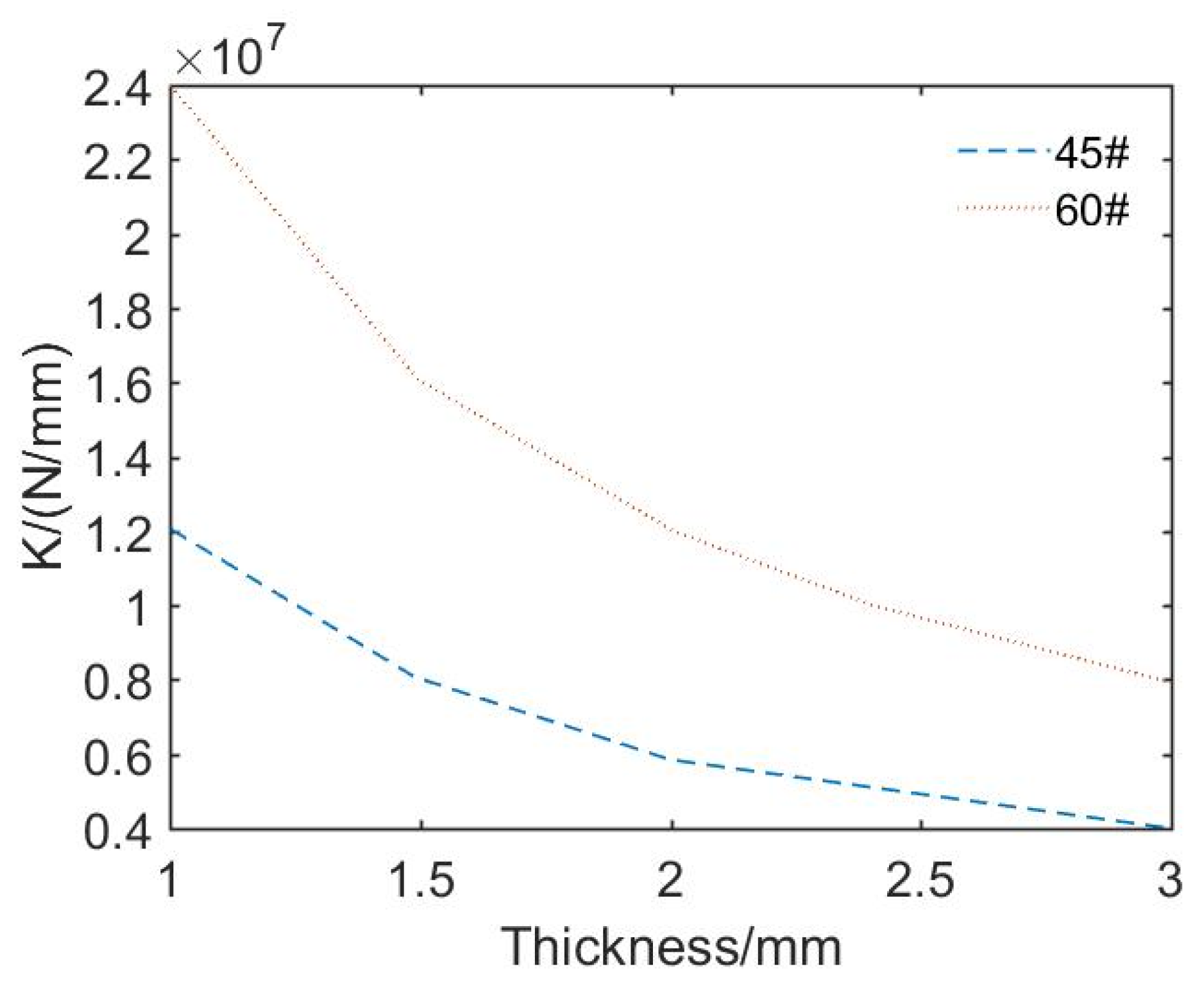
To further investigate the correlation between the thickness of the rubber and the lateral stiffness, a finite element simulation was carried out on the rubber layer based on the hyperelastic model of the COMSOL Multiphysics (version 5.4.) solid mechanics module, and the curve was obtained, as shown in
Figure 4 below.
The results show that for rubber with a shore A hardness of 45, the lateral stiffness of the rubber layer was greater than 4000 N/mm when the thickness of the rubber layer was within 3 mm, which meets the requirements for resistance against lateral stiffness.
2.2. Electromagnetic Actuator
As the active actuator of the hybrid vibration isolation system, the electromagnetic actuator is mainly composed of a copper coil wound in the stator core along the axial direction, with the mover embedded with a permanent magnet and C-type stator core. Permanent magnets are embedded axially in the upper and lower ends of the mover core, as shown in
Figure 5 below. Their N poles are radially outward.
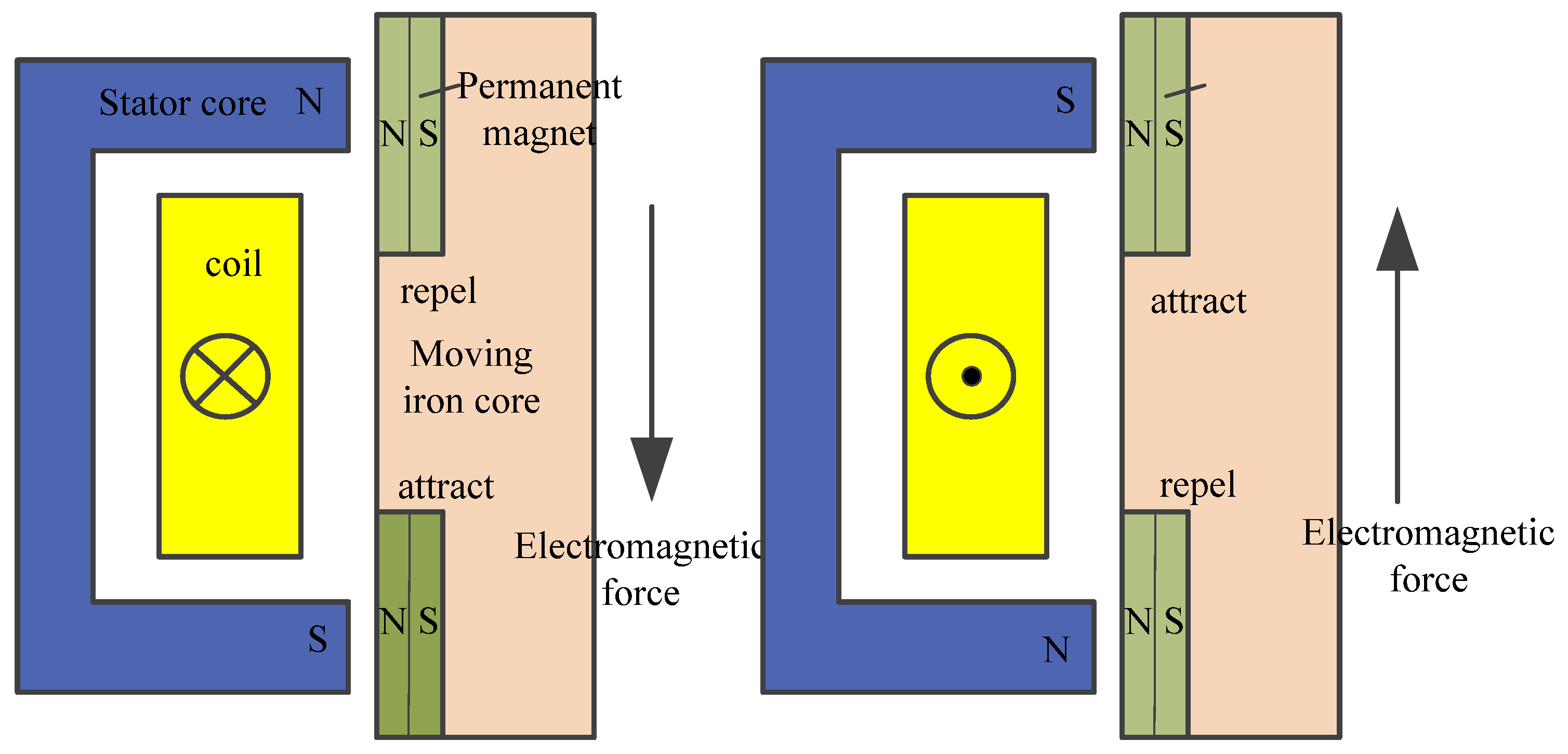
The working principle of the electromagnetic actuator is shown in
Figure 6. When an alternating current is applied to the coil, an alternating magnetic field is induced in the C-shaped area according to the electromagnetic induction principle. This turns the stator core into an electromagnet with alternating N and S poles at both ends. The two poles of the stator core are attracted or repelled by the permanent magnets embedded at both ends of the mover, which output alternating axial electromagnetic force between the mover and the stator.
In addition, in order to reduce the eddy current loss, the mover yoke and the stator yoke are provided with radial slots, with a structure shown in
Figure 7, to reduce the eddy current loss generated when the actuator is excited by a high-frequency current, as well as to improve the magnitude and linearity of the output force.
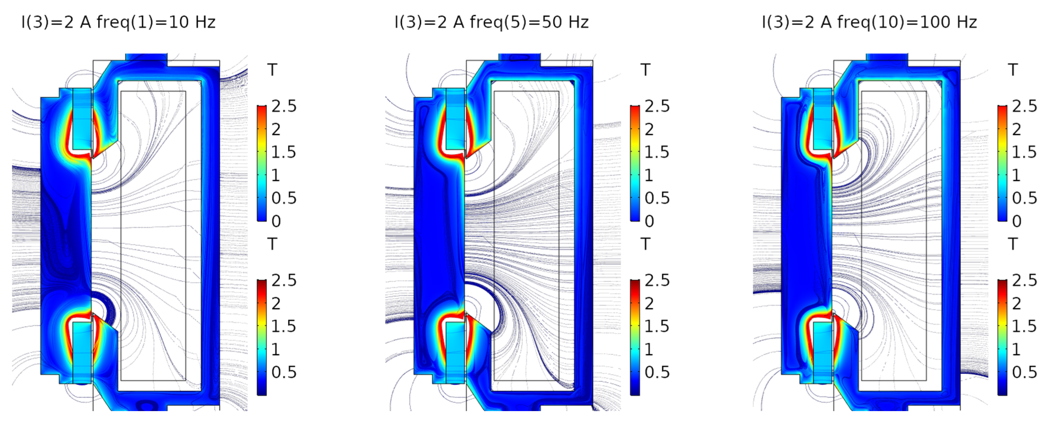
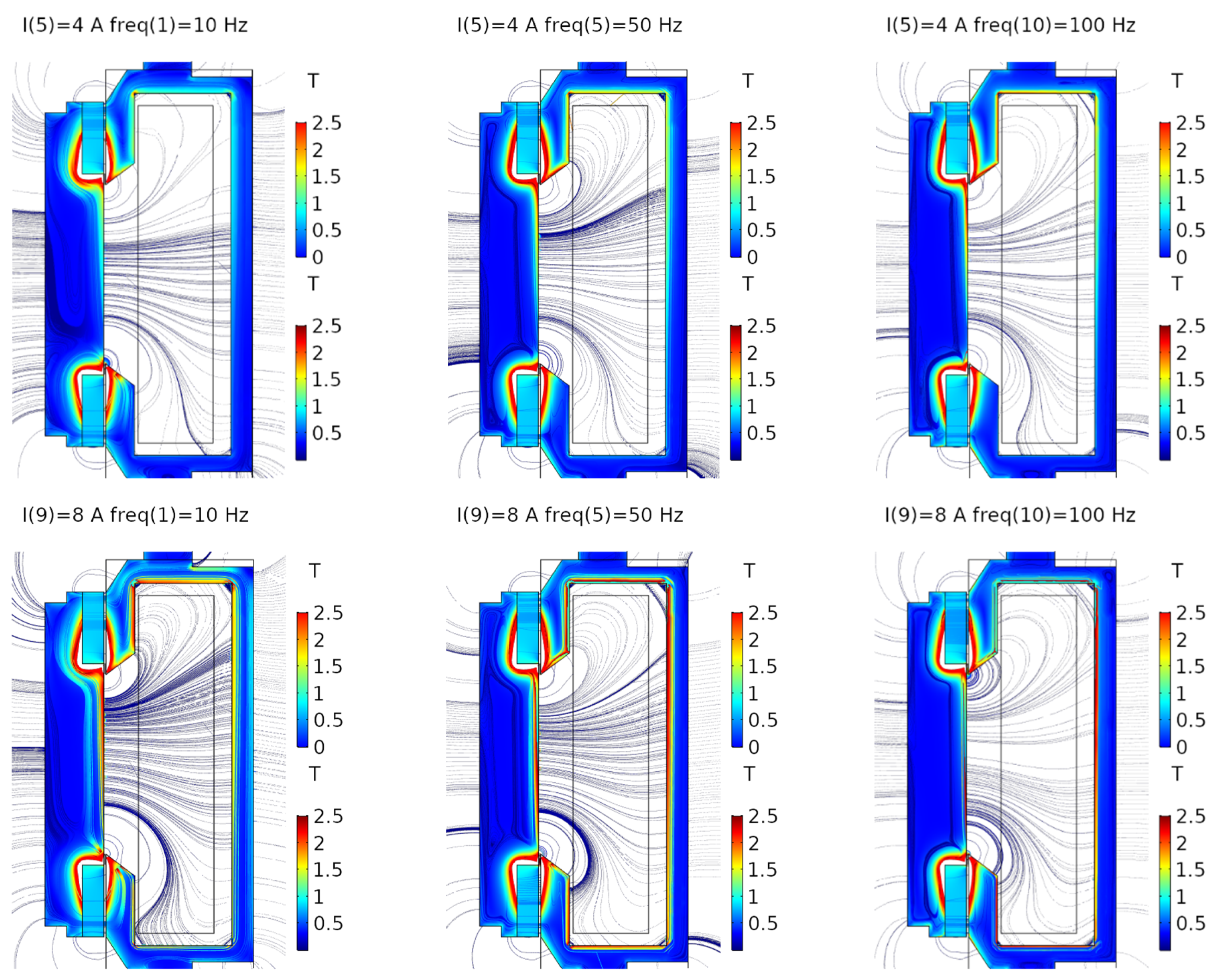
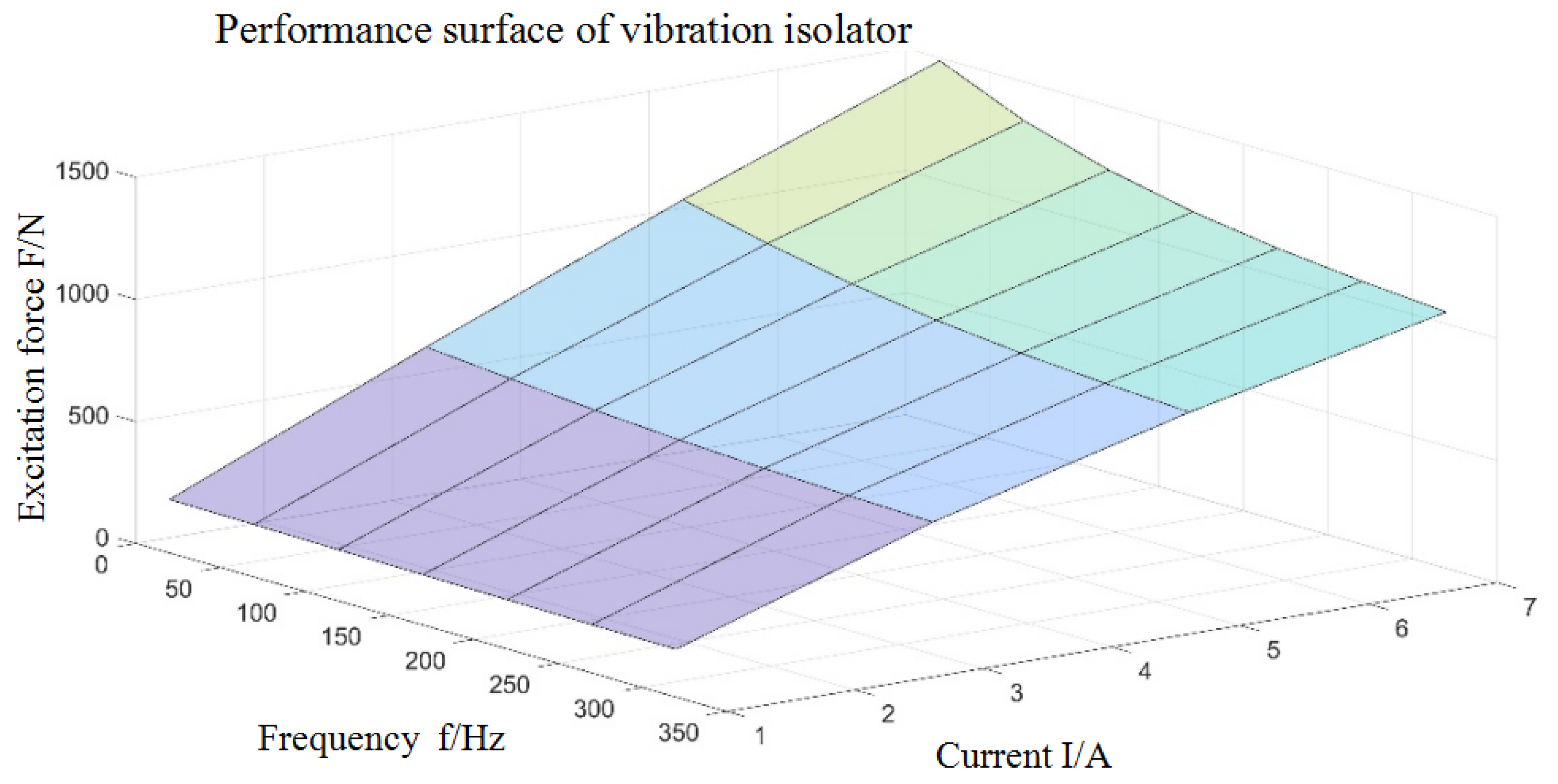
The relationship between the electromagnetic force and structural parameters was further studied. Using COMSOL Multiphysics, a two-dimensional electromagnetic simulation was carried out on the electromagnetic actuator. Arbitrary screenshots were selected to draw the structure, add materials (the mover and stator cores were made of DWSi3 silicon steel, which is a soft magnetic material, and the permanent magnet was made of N50 Ru-Fe-B, which has strong remanence), select the magnetic field interface to set the boundary conditions (the strength of the remanence and direction of the permanent magnet, the number of coil turns, the diameter of the coil, etc.), divide the grids and set the frequency-domain study. The magnetic induction intensity nephograms, output curves under different frequency domains and different current inputs were obtained, as shown in the following
Figure 8 and
Figure 9.
As can be seen from
Figure 8, the skin effect becomes increasingly obvious with the increase in the current frequency under the same current amplitude. In the meantime, the magnetic flux in the stator yoke increased and approached magnetic saturation along with the increase in the current.
As can be seen from the lines in
Figure 9, at a constant frequency, although the electromagnetic force generated per unit current gradually decreased due to the magnetic saturation limitation of the magnetic conductive material as the current increased, the current was basically in direct proportion to the output of the actuator under the condition of a nonhigh current. When the current is constant, because of the eddy current loss, the electromagnetic force output will decrease with the increase in frequency. But as the mover yoke and the stator yoke are provided with radial slots, this can effectively reduce the eddy current losses. In summary, this meets the design requirements.
After the basic geometric parameters and material parameters were determined using the two-dimensional electromagnetic simulation, the structure was modeled and simulated with three-dimensional electromagnetic–mechanical multifield coupling using JMAG 17.1 software. After the modeling was completed, the material parameters and boundary conditions were also set (the materials of the permanent magnet were radially magnetized, the materials of the stator and the mover were added and the coils were set), and then the permanent magnet, mover ring, stator core, air gap and air domain were meshed. Finally, time-domain research was added; three working conditions with current sizes of 1 A and frequencies of 12 Hz, 50 Hz and 300 Hz were set for the analysis. Magnetic flux density distribution nephograms and magnetic vector distribution nephograms under the three working conditions were obtained, as shown in
Figure 10.
Through the analysis of the cloud image, it was found that the magnetic flux density was the greatest near the air gap, and the magnetic vector gradually diffused as the frequency increased. Further analysis of the average loss power of the iron loss showed that the total average loss of iron was 0.2728 W at a low frequency of 12 Hz, 3.5 W at a frequency of 50 Hz and 60 W at a high frequency of 300 Hz, all of which meet the design requirements.
2.3. Rubber Vibration Isolator
The rubber vibration isolator was fixed on the base of the hybrid vibration isolation system, with the upper end connected in parallel with the electromagnetic actuator, and the magnetorheological damper installed inside. The structure of the rubber vibration isolator is shown in
Figure 11 below. The dynamic characteristics of the rubber vibration isolator are related to temperature, excitation frequency and acceleration, which directly affect the isolation effect.
Rubber vibration isolators react with different displacements when excitation forces of the same amplitude and different frequencies are applied, which is the dynamic stiffness characteristic,
, defined as the dynamic stiffness of the rubber vibration isolator, and its expression is
which describes the transfer function from the excitation force to the displacement of the rubber vibration isolator. In addition, the damping lag angle,
, is also an important parameter to measure the effect of the passive vibration isolation, and it describes the lag characteristics of the rubber vibration isolator after excitation.
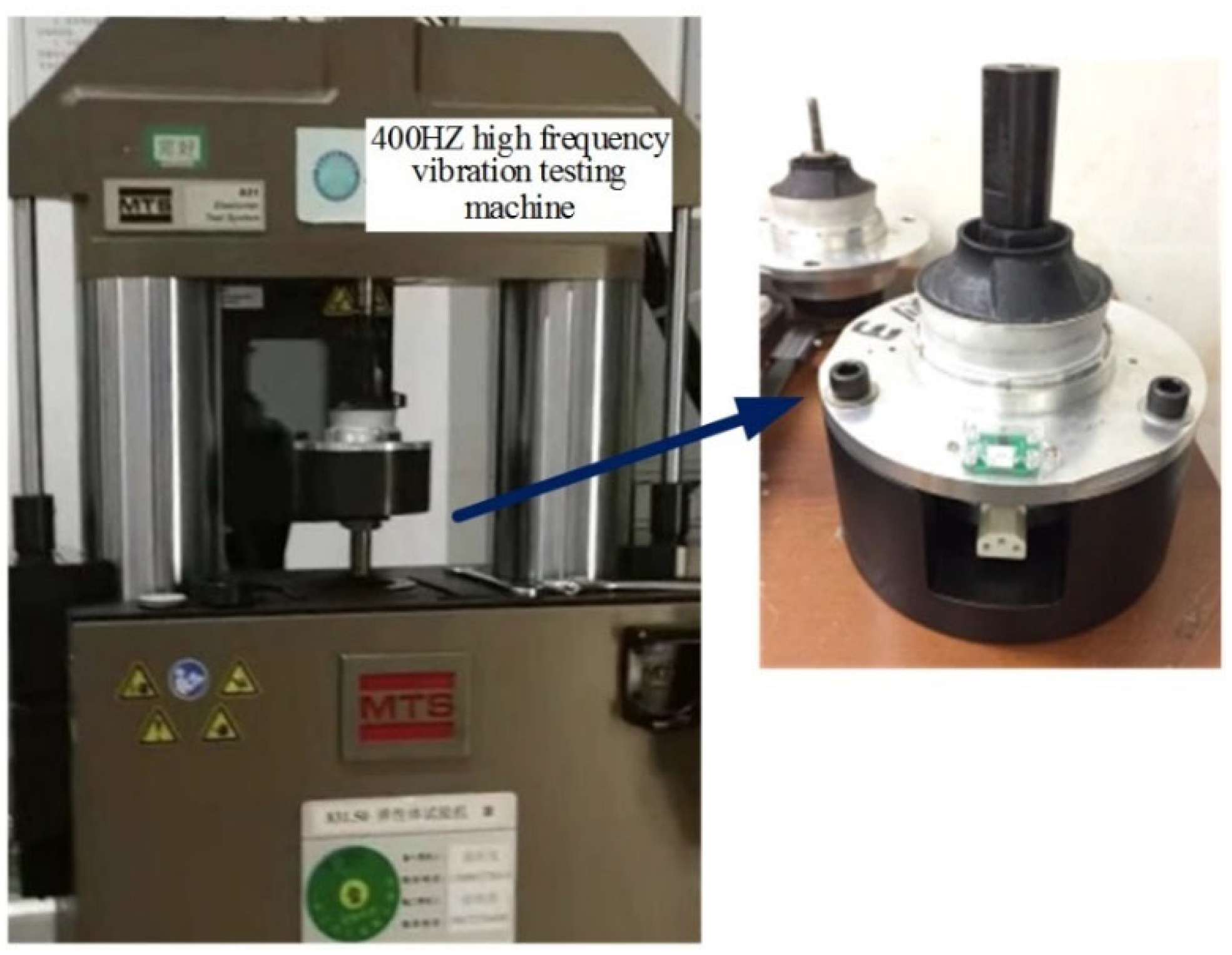
The axial dynamic stiffness and the damping lag angle characteristics of the rubber vibration isolator were tested on the MTS 831 dynamic performance testing machine. The MTS testing machine can provide 10 kN excitation in the frequency band of 0.01–1000 Hz. The integrated vibration isolator was installed on the fixture; the upper and lower ends of the testing machine are, respectively, the excitation rod and the test rod; and a displacement sensor and a force sensor are installed at the lower end. The test fixture is shown in
Figure 12.
At room temperature, 0.5 g of excitation force was applied to the rubber vibration isolator, and swept frequency excitation was performed in the range of 0–200 Hz at a rate of 1 oct/min, and the dynamic stiffness curve and damping lag angle curve of the rubber vibration isolator were obtained, as shown in
Figure 13 and
Figure 14, respectively.
The dynamic stiffness curve first decreased and then increased, and then it reached the minimum value at 18 Hz, suggesting that the displacement was maximum under the same amplitude excitation force; that is, the intrinsic frequency of the rubber vibration isolator was reached. The damping lag angle curve first increased, and then it reached the peak value near the intrinsic frequency of 18 Hz, and then it decreased with the increase in the excitation frequency. The test shows that the dynamic stiffness and damping lag angle are good in the low-frequency range, with high dynamic stiffness and large damping, but the dynamic stiffness remains large at high frequency. At this time, the electromagnetic actuator is required to output the electromagnetic force to reduce the displacement of the rubber vibration isolator and the dynamic stiffness of the system, thereby improving the vibration isolation performance.
3. ASFXLMS Algorithm
In the process of adaptive control, when the system is strongly disturbed by the external environment, this will lead to a sharp increase in error signals and a dramatic change in the control coefficient, which will make the output signal exceed the effective working range of the actuator, eventually resulting in the divergence of the control system. Therefore, the output signal of the controller should be constrained and the amplitude should be limited within the saturation region of the actuator. In this paper, an ASFXLMS (adaptive suppression filtered-x least mean square) algorithm is proposed, and the suppression factor is introduced on the basis of the FXLMS algorithm to adjust the update of the control weight coefficient. The schematic diagram is shown in
Figure 15.
The FXLMS algorithm combines the adaptive filtering algorithm with the secondary channel filtering structure to update the weight vector,
, which is widely used in the field of active control. The schematic diagram of the algorithm is shown in
Figure 16.
The iterative formula for the weight coefficient of the FXLMS algorithm is
where
is the filtered signal vector,
,
,
is the secondary channel estimation model,
is the residual signal,
is the convergence factor with a value range satisfying
where
is the maximum eigenvalue of the autocorrelation matrix
.
In order to prevent overflow, it is necessary to restrict the output signal of the controller. In an ideal state, the function output can be written as
where
is the constraint threshold, and
is the round operation; that is, when the threshold is exceeded, amplitude limiting is carried out; and when the threshold is not exceeded, the update is originally carried out according to Formula (2).
Based on the nonlinear output of Formula (4), the Lagrange function is introduced to obtain the extreme value to ensure the accuracy and convergence speed of the active control. The objective function is set as
The derivatives of
and
are taken, respectively, as:
The results of Formula (6) are all set as zero to obtain:
The suppression factor can be written as
, as can be seen from Formula (4), in an ideal state as
Next,
is introduced in Formula (2) to modify the update of the weight coefficient, and the formula for the ASFXLMS algorithm is obtained as
According to the output form of Formula (10), an arc tangent function can be adopted, for example
The derivative function is obtained as
where
A is the coefficient related to the threshold, and
can adjust the window width of the derivative function.
4. Active Control Experiment
In order to verify the performance of the active–passive hybrid vibration isolation system and the effectiveness of the adaptive suppression algorithm, the algorithm is developed using NI LabVIEW, and an active control experimental platform is built by combining the NI PXI real-time acquisition and control system. A low, medium and high multiline spectrum excitation experiment was carried out taking the vibration exciter as the control object, the hybrid vibration isolation system as the active control actuator and the ASFXLMS algorithm as the control law. The experimental model is shown in
Figure 17. The upper layer of the experimental bench was equipped with an electromagnetic vibration exciter, and the lower plate was fixed on the ground. The periphery of the lower plate was provided with a column guide rail using bolts, and the upper plate matched the column with roller sliding bearings. The hybrid vibration isolation system was bolted between the upper and lower plates. The vibration exciter, upper plate and lower plate were each equipped with an acceleration sensor to collect the active control reference signal, upper primary vibration signal and lower residual vibration signal. The lower residual vibration signal was used as the error signal of the active control algorithm.
The experimental equipment mainly included the NI PXI control system (including the PXI 8840 adaptive controller, PXI 4498 AD acquisition board and PXI 6733DA output board), Copley Xenus servo drive, PCB acceleration sensors, electromagnetic vibration exciter, WYK-20040K DC stabilized current power supply, etc. The electromagnetic exciter was independently developed, which is essentially an electromagnetic actuator, and the output force had a linear relationship with the input current amplitude in the low-frequency excitation range.
The signal generation module generated an excitation signal, which was generated by the servo drive to the electromagnetic exciter to conduct vibration interference. The PCB acceleration sensors acquire the reference signal, the upper primary signal and the lower error signal into the PXI 8840 adaptive controller via the PXI 4498 AD acquisition board. The output control signal enters the Copley Xenus servo drive via the PXI 6733DA output board, which drives the active and passive hybrid vibration isolation system to generate secondary vibration to suppress the primary vibration.
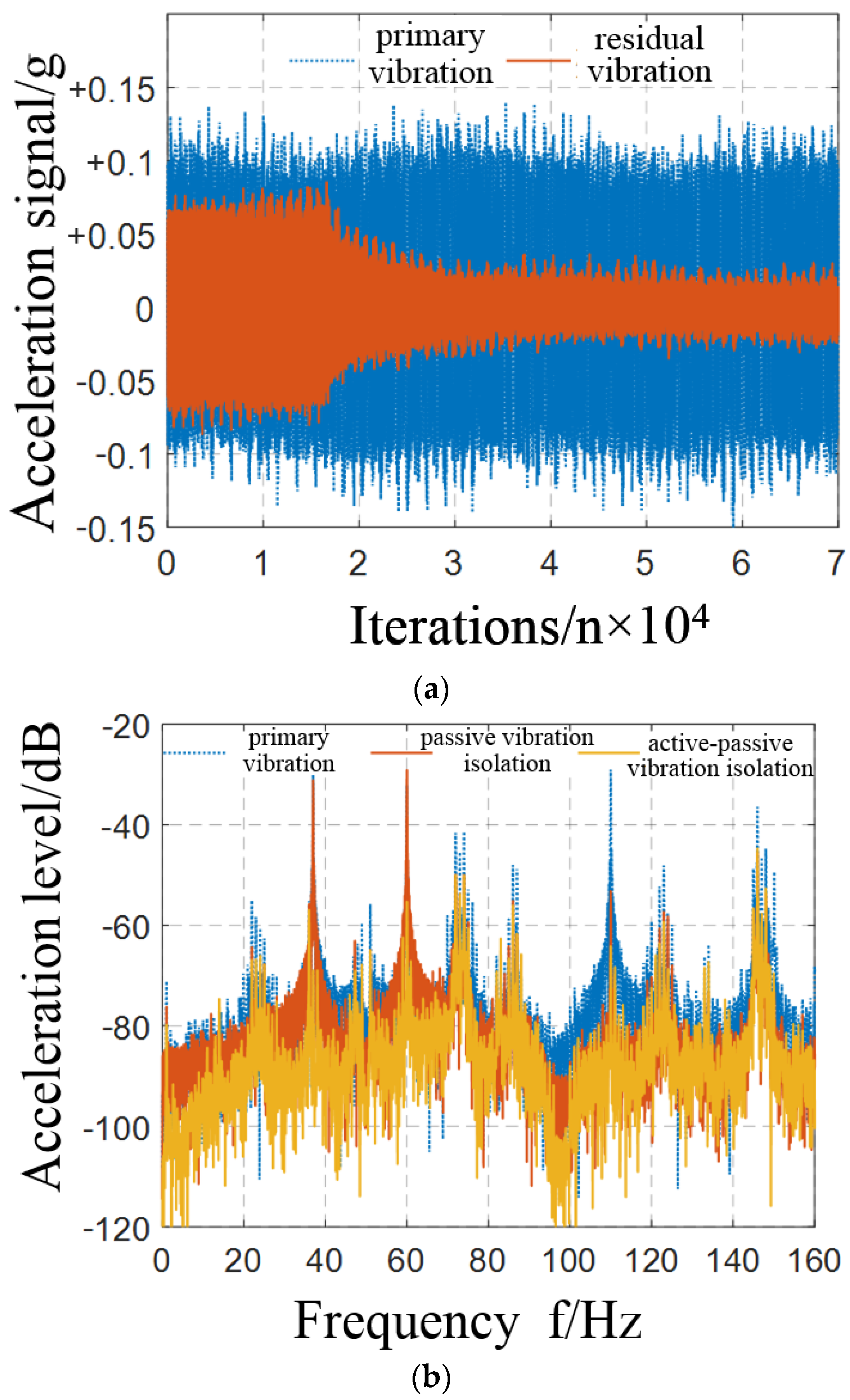
Superimposed harmonic signals of 37 Hz, 60 Hz and 110 Hz with currents of 8 A were generated with the signal generator as the initial excitation signals. The length of the control filters was 300 orders. The iterative step size of the algorithm was 0.00001. The sampling frequency was set to 10 kHz, which not only satisfied the sampling theorem but also ensured the real-time tracking of the signal. A Butterworth band-stop filter was designed in the experiment to filter out the 50 Hz power frequency interference in the signal collected by AD board. The drop between the primary vibration signal and the residual vibration signal was taken as the evaluation standard, and the passive vibration isolation and active–passive vibration isolation effects were obtained before and after the control was turned on. After the experiment was carried out for 2 s, the algorithm control was started. The obtained time–frequency domain control effect and input current amplitude are shown in
Figure 18 and
Figure 19.
The passive vibration isolation effect of the hybrid vibration isolation system is shown before the active control was turned on. From the time-domain diagram, it can be seen that the residual vibration was reduced by 25% compared to the primary vibration, and there was no vibration isolation effect on the 37 Hz and 60 Hz line spectrum in the frequency domain, and the 110 Hz line spectrum was attenuated by 24.16 dB. It can be seen that the hybrid vibration isolation system achieved a certain vibration isolation effect at a high frequency. After the active control was turned on, the error signal converged quickly in the time domain, and the amplitude was reduced by more than 80%. In the frequency domain, the 37 Hz and 60 Hz line spectra were attenuated by 38.86 dB and 26.16 dB, respectively, the 110 Hz line spectrum was attenuated by 11 dB on the basis of the passive vibration isolation, and the control effect is good. At the same time, it can be seen that the input current was well constrained within 8 A, which shows that the adaptive suppression algorithm can well constrain the output signal under large interference and ensure that the electromagnetic actuator can effectively isolate the vibration within the normal excitation current.
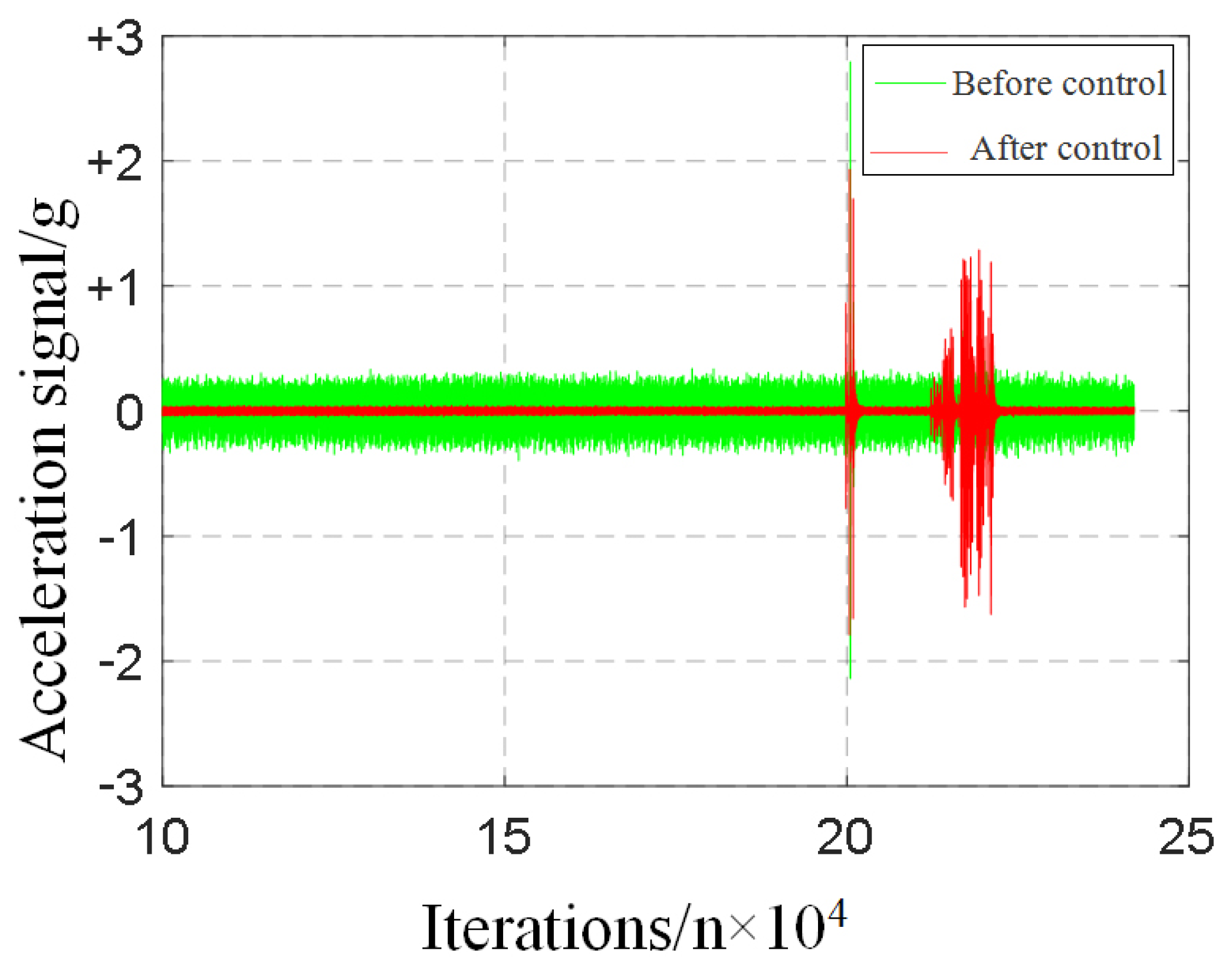
The robustness of the algorithm was further verified. When the experiment ran for 20 s, an impact was applied to the system base, and the error signal could quickly be stabilized. In addition, when the shock was applied again between 21 and 22 s, the error signal could still quickly be stabilized to the convergence value. The acceleration response time history is shown in
Figure 20. Through the continuous impact on the system, it was shown that the suppression algorithm could still effectively control the output signal. When the error signal increased sharply, the weight increment
tended to zero, so that the weight coefficient of the controller remained unchanged; therefore, it is concluded that the ASFXLMS algorithm has a strong anti-interference ability.


