Article

The Effect of Hydrophilic Surface Coating of Fins on the Performance of Fin-and-Tube Heat Exchangers

1
Department of Industrial Technology Education, National Kaohsiung Normal University, Kaohsiung 82444, Taiwan
2
Department of Electronic Engineering, Minghsin University of Science and Technology, Hsinchu 30401, Taiwan
*
Author to whom correspondence should be addressed.
Appl. Sci. 2023, 13(18), 10450; https://doi.org/10.3390/app131810450
Submission received: 4 September 2023 / Revised: 16 September 2023 / Accepted: 17 September 2023 / Published: 19 September 2023
(This article belongs to the Topic Applied Heat Transfer)

Abstract

:
With the rapid progress in data mining, deep learning, and artificial intelligence, the demand for datacenters of various sizes increases globally. Datacenters typically require an environment with properly controlled temperature and humidity conditions for their proper operations. These needed environmental conditions are always provided by an air conditioning system. In humid and hot regions, both energy consumption and the splash of water condensate in using the fin-and-tube heat exchangers are of concern because reliability issues can occur. In this study, the effects of fin surface hydrophilic/hydrophobic coatings on the performance of the fin-and-tube heat exchangers, including the heat transfer rate, pressure drop, and water-condensate splash, were investigated experimentally. By varying the cooling air speeds and fin pitches, the results show that hydrophilic surface coating is an effective method in reducing both the pressure drop (thus saving energy) and the condensate splash, while not affecting the heat transfer rates significantly. The water splash reduction is achieved by both the increased air speed for splashing and a smaller amount of splashing. Water splash can even be completely eliminated if the airspeed was below about 3 m/s. In contrast, hydrophobic surface coating will increase both pressure drop and water splash; thus, should be applied with caution.

1. Introduction

The quest for data mining, artificial intelligence, online data streaming, and rapid progress in edge and cloud computing has recently driven the demand for datacenters of various scales globally. In order to make these datacenters reliable, their environmental conditions, especially the humidity and temperature, have to be well controlled through proper HVAC systems. Compared to domestic HVACs, the environment for datacenters is of less concern to human comfort in terms of airspeed or noise. However, the control of humidity and temperature is more critical as they could cause reliability issues in datacenters.
For large datacenters, the environmental air is typically channeled through a series of HVACs. In contrast, for datacenters of medium and small sizes, precision air conditioning (PAC) units are usually adopted. A typical PAC unit consists of an outdoor part and an indoor part. The outdoor part includes mainly the condenser and the cooling fans; whereas the indoor part has compressors, expansion valves, evaporators, fans, humidifying chambers, and heaters. These latter components are usually arranged compactly so that the indoor space can be utilized effectively. In regions of both high temperature and humidity, such as Taiwan, if the datacenters were not hermetically constructed and the entrance doors were open frequently, the humidity of the respective indoor environment would be high and could lead to water-condensate splash at the air outlets. It is known that the splash of water condensate is detrimental to the reliability of electronic components and systems. On the other hand, an improper dry environment could cause unwanted electro-static discharges. Thus, proper controlling of the environmental humidity level is essential for the reliability of the associated electronic components and systems. Moreover, datacenters tend to be operated continuously throughout the year. Hence, their power consumption is also of great concern. Thus, the goal of this research is to examine the performance of different surface-treated fins of the fin-and-tube heat exchangers in terms of flow resistance, heat transfer rates, and water-condensate splash.
The commonly adopted fin-and-tube heat exchanger of indoor PACs generally consists of a copper tube with aluminum fins coupled with cooling fans for heat exchange between the refrigerant/ice water inside the tube and the surrounding air outside the tube. In the process of heat exchange, the surrounding air could be cooled down to its dew point to result in water condensation on the fin and tube surfaces. The water droplet size of the condensate will grow as the heat exchange proceeds further. When the water droplet size becomes larger, the droplets can merge together to form a water bridge between the fins. Both condensate and bridging will increase the airflow resistance through the tube and fin surfaces and simultaneously decrease the heat exchange efficiency. Furthermore, the condensate of large water droplets can be easily carried away by the cooling air, leading to water splash which can cause damage to the nearby electronic equipment. The factors causing water splash are multiple, including the geometries and surface conditions of the fins and tubes. Among these influencing factors, the present research focuses on surface hydro conditions, fin pitches, and air speeds with the goal of reducing both water splash and energy consumption. The surface hydro conditions in terms of wettability were varied by surface coating.
The fin-and–tube heat exchangers can perform either in a dry situation without latent heat exchange or a wet situation with latent heat exchange. When acting as an evaporator, they always perform in a wet situation because of the water-condensate formation on the fin and tube surfaces. According to TIA-942 [1], the environmental conditions of a datacenter are the dry bulb temperature being 18–27 °C, the maximum relative humidity being 60%RH, the maximum dew point being 15 °C, and the maximum temperature variation being no greater than 5 °C/h. However, in the regions of hot and wet environments, the formation of water condensate on the fin-and-tube heat exchangers in datacenters is common. Therefore, to meet the guidelines of GBT 19413-2010 [2], various studies using surface coating have been conducted. As examples, for wavy fins, Ma et al. [3,4] showed that hydrophilic surface coating could reduce the pressure drop significantly due to the presence of film condensate. Similarly, Liu and Jacobi [5] also showed that increasing surface wettability could reduce the pressure drop significantly while not significantly reducing the heat transfer coefficient. Wang and Chang [6] also showed that hydrophilic coating would significantly reduce the airflow resistance, a larger reduction with a bigger inlet relative humidity. Hong et al. [7] showed that by dry/wet cycling the contact angle of most commercial coatings increased with increasing numbers of dry/wet cycles, reaching the 55° to 65° range after 1000 cycles. Dry/wet cycling could also improve the wettability of the uncoated surface, believed to be due to surface oxidation and contamination. Min and Webb [8] indicated that for the surfaces with a smaller contact angle, the generation of splash water and water bridging was less likely. Kim et al. [9] showed that the critical air speed of water splash for completely wetted fin surfaces was twice that of partially wetted fin surfaces; moreover, for the prevention of water splash, the contact angles had to be smaller than 60°. Navarro-Peris et al. [10] showed that for the uncoated fin surfaces, the pitch between the fins had to be greater than 3 mm to avoid water bridging; furthermore, hydrophilic fins could reduce the water splash situation without reducing the heat transfer rate of the fin-and-tube heat exchanger. In contrast, Qi et al. [11] showed that the water droplet formation cycle shortened and the splashing droplet diameter reduced as the contact angle increased.
Numerically, Zhuang et al. [12] explored the bridging phenomena by adding gravity effects; whereas Zhuang et al. [13] examined the dehumidifying behavior of water droplets which was validated by Zhuang et al. [14].
It is clear that the reduction in both energy consumption and water splash is important to the equipment of datacenters. Therefore, this study focuses on these two aspects quantitatively by taking the fin density and airspeed as the controlling parameters to further substantiate the effects of hydrophilic surface coating explored in the literature.

2. Heat Exchanger Fabrication

In this study, three types of fin surfaces of the fin-and-tube heat exchanger were examined. The first was the usual uncoated fin made of aluminum alloy. The second was the surface-coated hydrophilic blue fin using the same aluminum alloy as the substrate which is typically used in industry for corrosion prevention. The third was the surface-coated hydrophobic fin for preventing excessive corrosion using the same Al substrate. The compositions of the aluminum alloy included Al (about 99 wt%) as the main material and the rest was a total of about 1 wt% of Si, Fe, Cu, Mn, and Zn. The tensile strength and thermal conductivity of the alloy were about 118 N/mm2 and about 220 W/m-K, respectively. The symbol wt% represents the weight percentage.
The hydrophilic surface coating (with a thickness of 5 µm) consisted of two layers. One was the corrosion-resist base layer which was an inversion-coated aluminum chromate film (with a thickness of about 0.13 µm). On top of the base layer was the spray-coated hydrophilic film which consisted of a mixture of organic and inorganic materials. The coated film passed 160 h in the flow and salt spraying tests for 500 h according to JIS Z 2371 [15] to ensure its reliability. Practical field applications show that the coating still performs well for more than three years. The hydrophobic surface coating was essentially the same as that of the hydrophilic coating, except that the hydrophilic layer was replaced by a corrosion resistance layer to further prevent corrosion. That is, in terms of the capability of corrosion prevention, hydrophobic coating provides the best results, followed by hydrophilic coating, and then uncoated surfaces. In terms of cost, the hydrophilic coating is more expensive, whereas the uncoated ones are cheaper. In other words, if corrosion were the key issue, a hydrophobic coating is necessary, as is currently practiced in industry. However, hydrophobic coating could lead to the undesirable effect of water splash. Thus, a hydrophilic coating which costs slightly more can prevent corrosion and might also mitigate water splash and deserves further investigation.
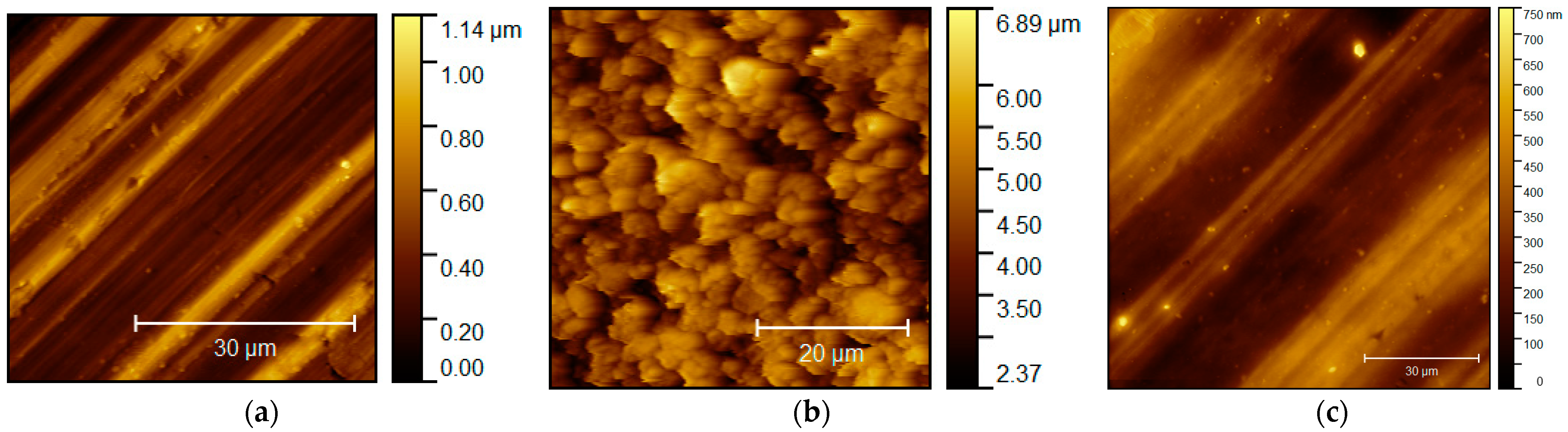
The surface morphologies of the uncoated and coated aluminum alloys are depicted in Figure 1 by AFM (Atomic force microscope, Nanosurf easyScan2, Liestal, Switzerland). The surface of the uncoated Al alloy, as shown in Figure 1a, exhibits the ridge-valley line type roughness resulting from the fabrication process and has a shiny appearance due to the metal reflectivity of the Al. In contrast, the coated hydrophilic surface, as shown in Figure 1b, shows a more uniformly distributed protrusive type roughness (roughness of about 0.7 µm) and has a dull light blue appearance. Moreover, the observable color difference between the uncoated and hydrophilic coated fin surfaces prevents the misuse of either one in practical applications. On the other hand, the surface hydrophobic coated surface, as shown in Figure 1c, is geometrically similar to that of the uncoated one and could be misused.
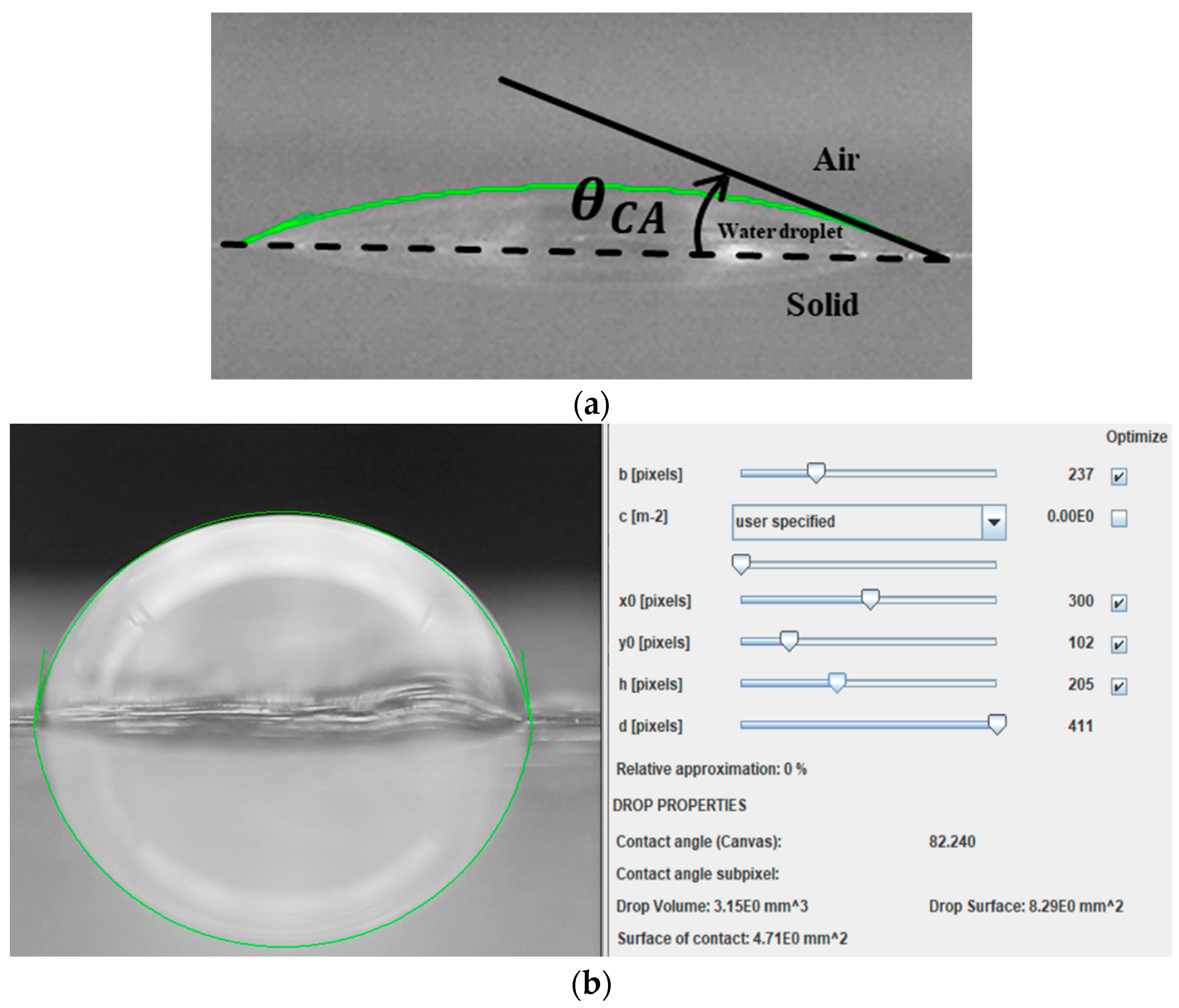
The contact angle (θCA) is the water droplet angle at the interface of the water droplet, air, and solid surface as illustrated in Figure 2a. It is always used to quantify the wettability of a solid surface. The contact angle of the fin surface was measured by an image method utilizing the Young–Laplace equation (Stalder, et al. [16]) using a water droplet size of 5 µL. Typical results for the three types of surfaces are illustrated in Figure 2b–d, respectively. The contact angles of the uncoated, hydrophilic coated, and hydrophobic-coated surfaces are 85 ± 5°, 35 ± 5°, and 95 ± 5°, respectively. A difference of about 50° in the contact angles between the uncoated and hydrophilic-coated aluminum fin surfaces is significant for the present study. The contact angle of 35 ± 5° of the coated surface also meets the suggestion of Kim et al. [9].
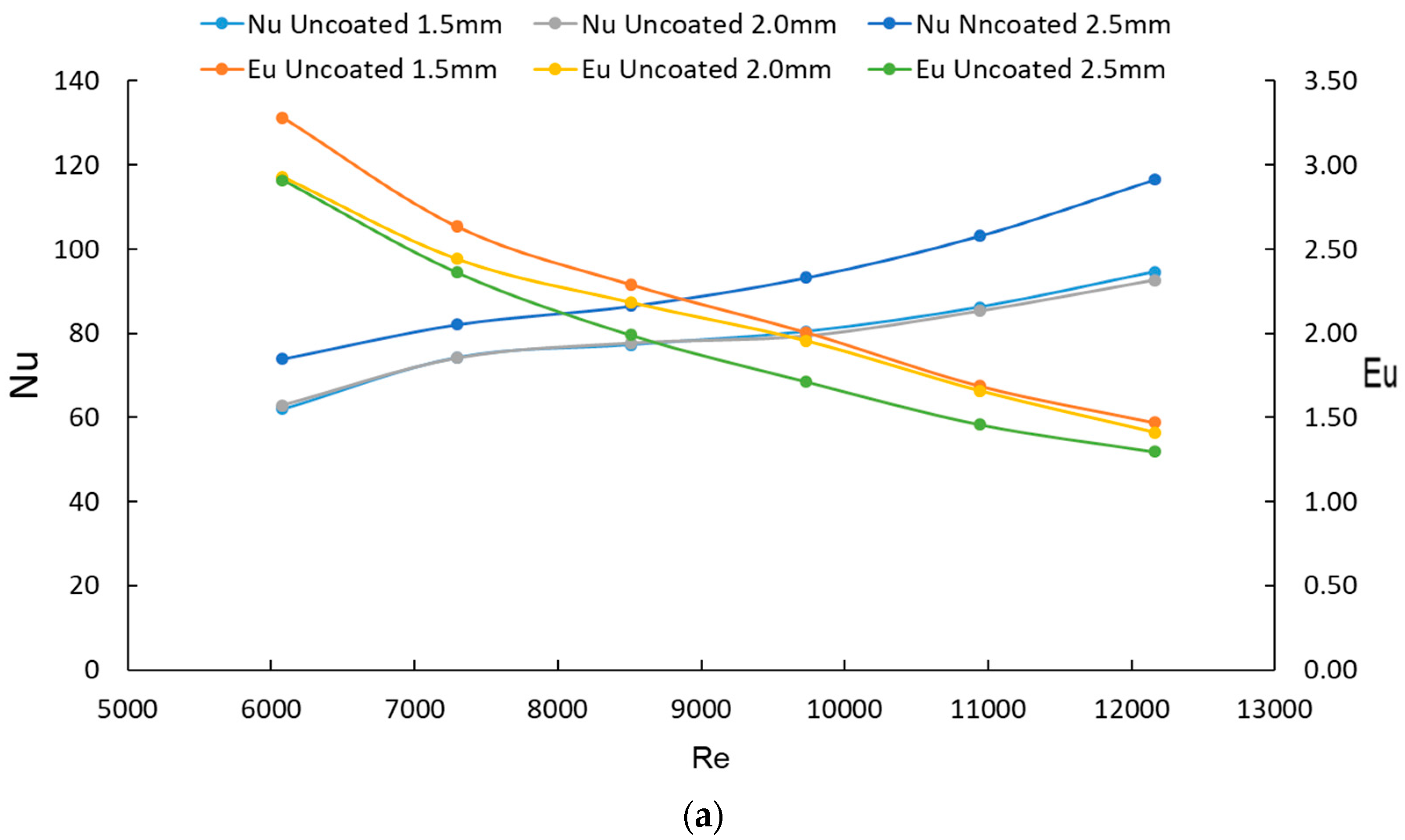
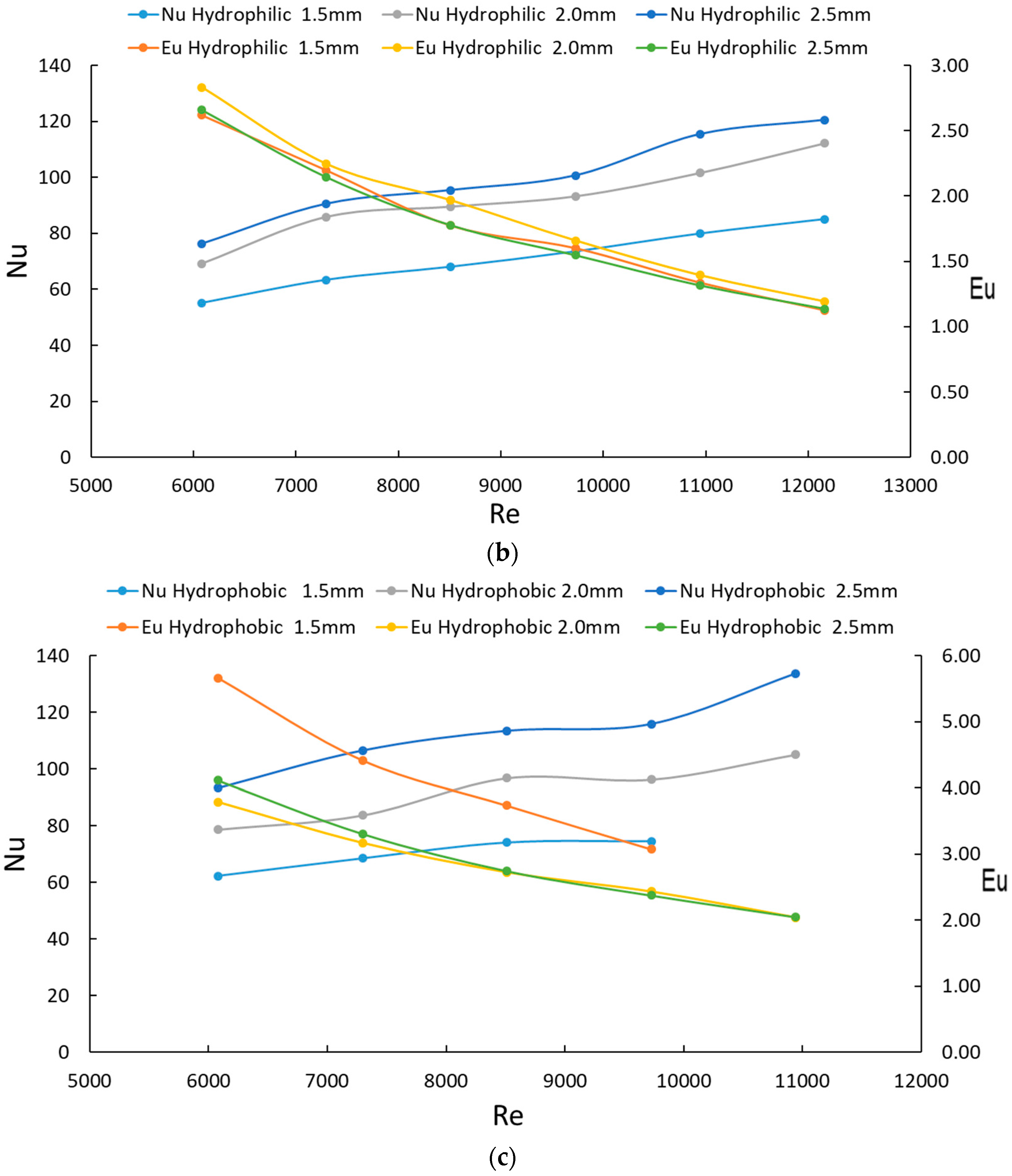
As the heat transfer and pressure drop, characteristics of the fin-and-tube heat exchangers are affected by both fin pitches [3,5,17] and air speeds [
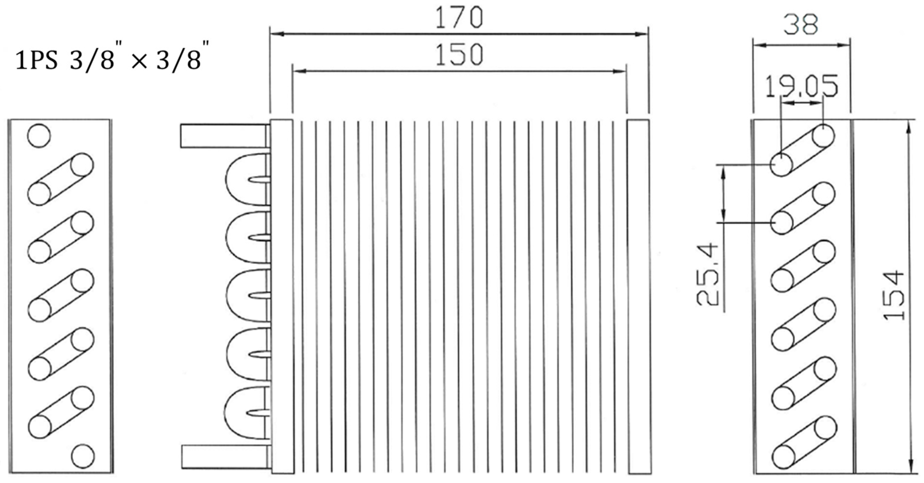
18], the fin pitch and airspeed were chosen as the experimental parameters for the present study. Details of the geometry and sizes of the fabricated heat exchangers, using the three types of fin surfaces, are illustrated in Figure 3 and listed in Table 1, respectively.
Briefly, three fin pitches of 1.5 mm, 2.0 mm, and 2.5 mm were examined. This range was selected for its higher heat exchange efficiency [19] and also because it is typically used in industry. The height, width, and thickness of the heat exchangers were kept to the constant values of 154 mm, 170 mm, and 38 mm, respectively; the thickness of the fin was 0.1 mm. However, due to the limitations of the mold and the fabrication process, fin densities in terms of FPI (number of fins per inch) for the coated and uncoated surfaces were slightly different. For example, the FPIs for the coated and uncoated fins of pitch of 1.5 mm were 18 and 16.3, respectively.
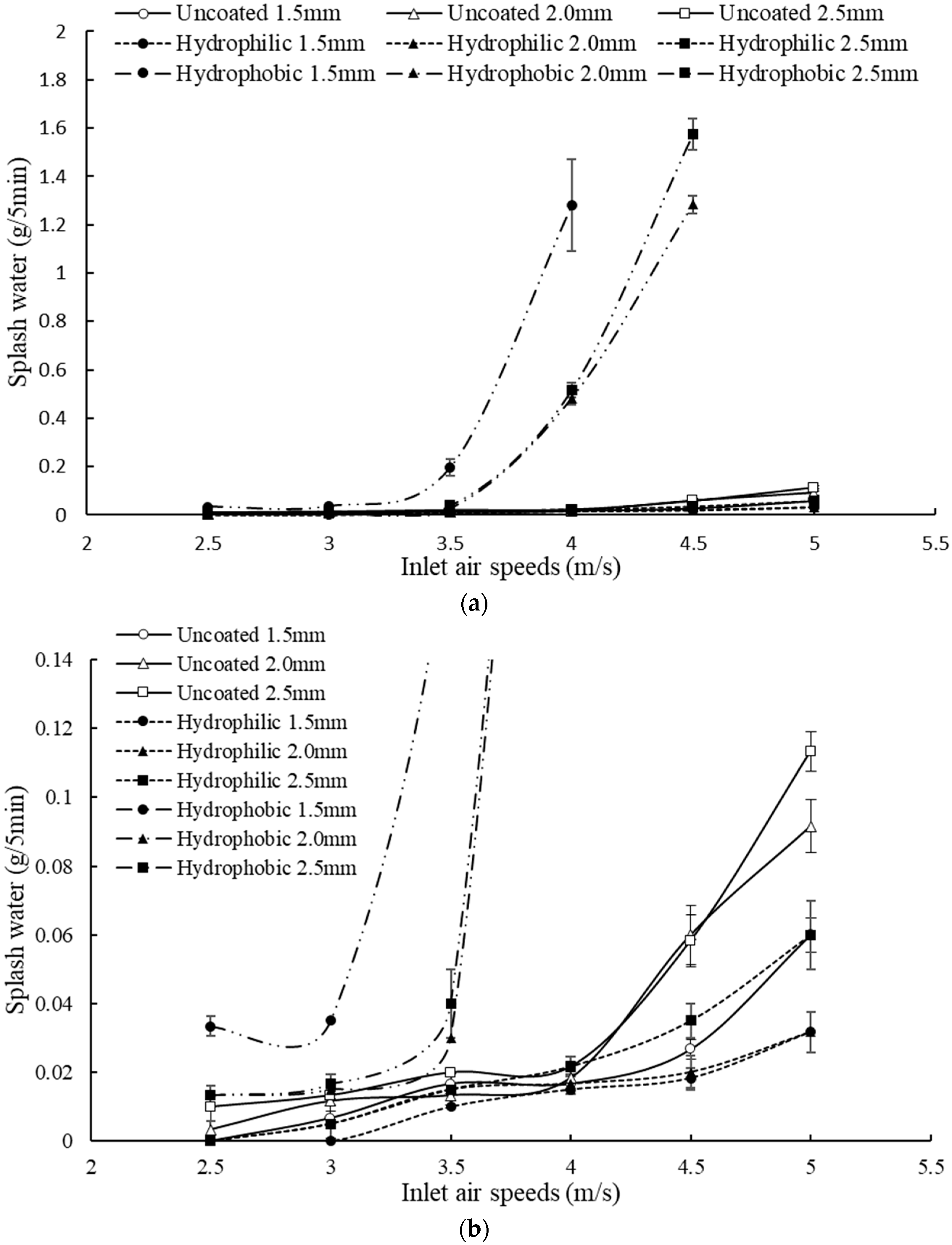
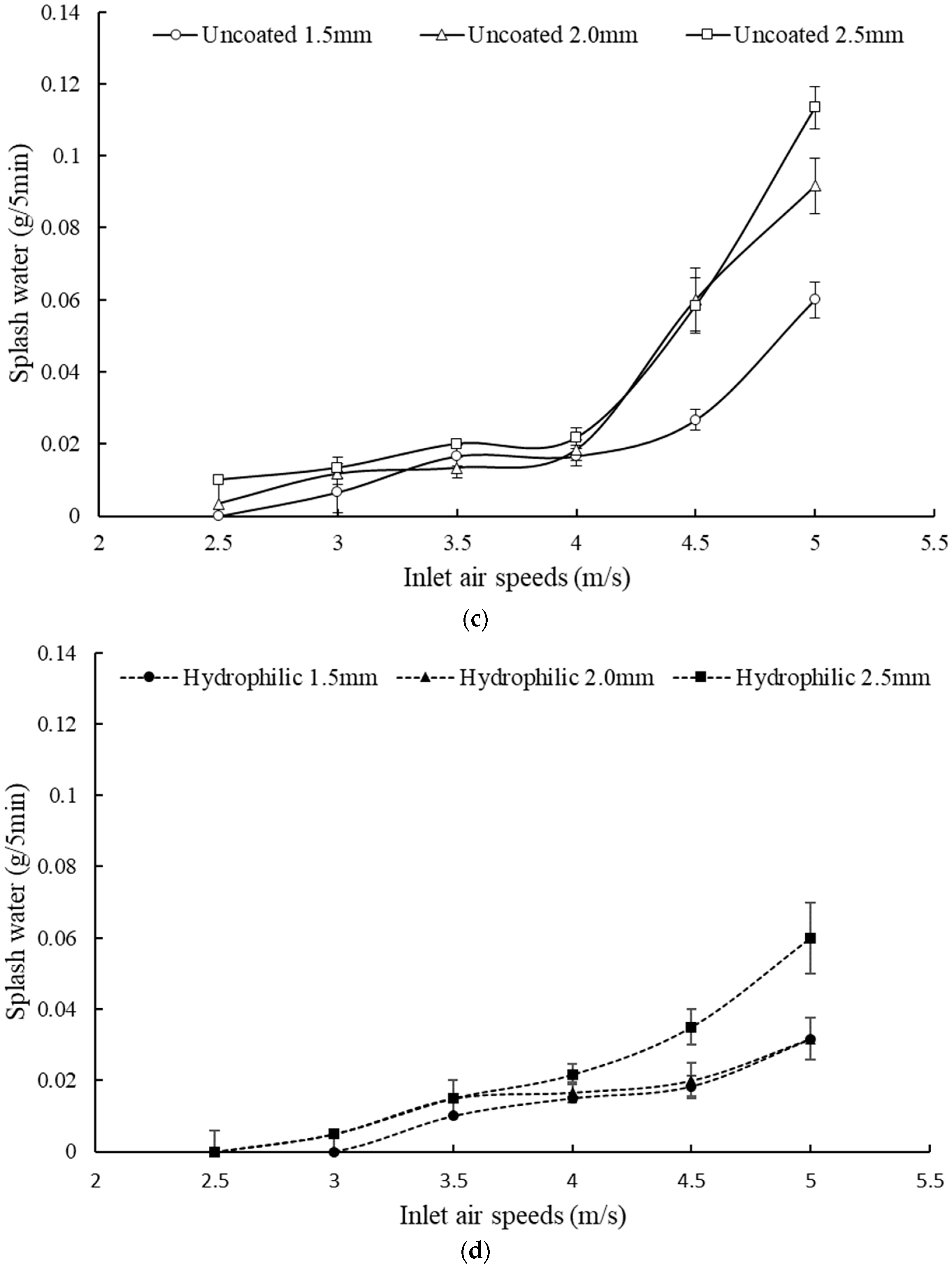
The air speeds were varied from 2.5 m/s to 5 m/s. In the industry, the air speeds are typically 0.5 to 1.5 m/s, 1.5 to 3 m/s, 3 to 4 m/s, and 4 to 5.5 m/s for dehumidifying, low load operations, nominal operations, and heavy load operations, respectively. That is, the present air speeds cover the operations from the upper end of the low load to the heavy load range. The operations at the smaller air speeds were not considered because it was expected that water splash would occur at higher air speeds.

3. Experimental Approach

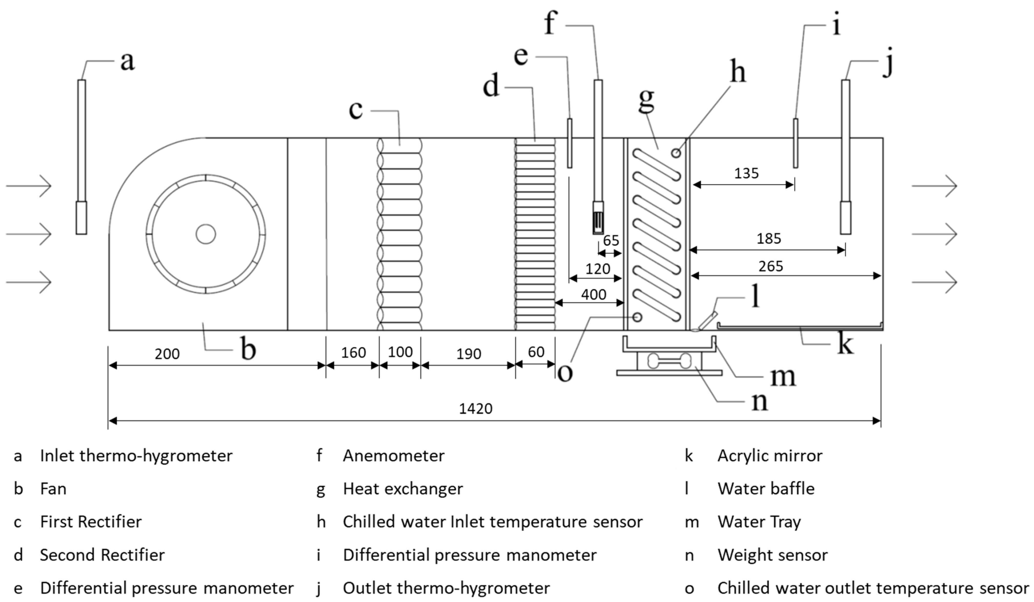
A schematic diagram of the airflow channel of the present study is depicted in Figure 4, including mainly a centrifugal fan, two-stage flow straighteners, and a heat exchanger section with a mirror water tray for collecting the water condensate. The flow channel was an open-type facility with a rectangular cross-sectional area made of acrylic plates. The dimensions of the channel were 1420 mm (length) by 170 mm (width) by 154 mm (height). The channel was designed in such a way that different heat exchangers could be installed for various tests. A fan of 135 W (TF 150, Shenzhen, China) was used to deliver the airflow. The temperatures of the cooling air and chilled water were measured by Rotronic HC2a-s (accuracy of ±0.15 °C) and Sensor PT100a (accuracy of ±0.15 °C), respectively. Air humidity was also measured by Rotronic HC2a-s (accuracy of ±1%). The airspeed and pressures were measured by Sailsors tf100 (accuracy of ±3%) and Nagono Keiki GC52 (accuracy of ±1%), respectively. Industrial experience indicates that water splash could occur in the datacenters with the indoor temperature and humidity being 24.5 °C and 76%RH, respectively. Hence, the present test environment was kept at the condition of constant temperature and humidity of 24 °C and 80%RH, respectively, by using PID controllers to control the electric humidifier and heater while maintaining the chilled water inlet temperature at 7 °C.
The air-side heat transfer rate was obtained using the air enthalpy difference deduced by the measured airspeed, the dry bulb temperature, and the relative humidity according to ASHRAE Handbook [20]. The dry bulb temperature and the relative humidity were used to determine the enthalpy and heat capacity properties of the air for the calculation. The amount of the splashed water was determined by averaging the water droplet weights which were collected continuously by the water tray (denoted by the symbol m in Figure 4) for five minutes.
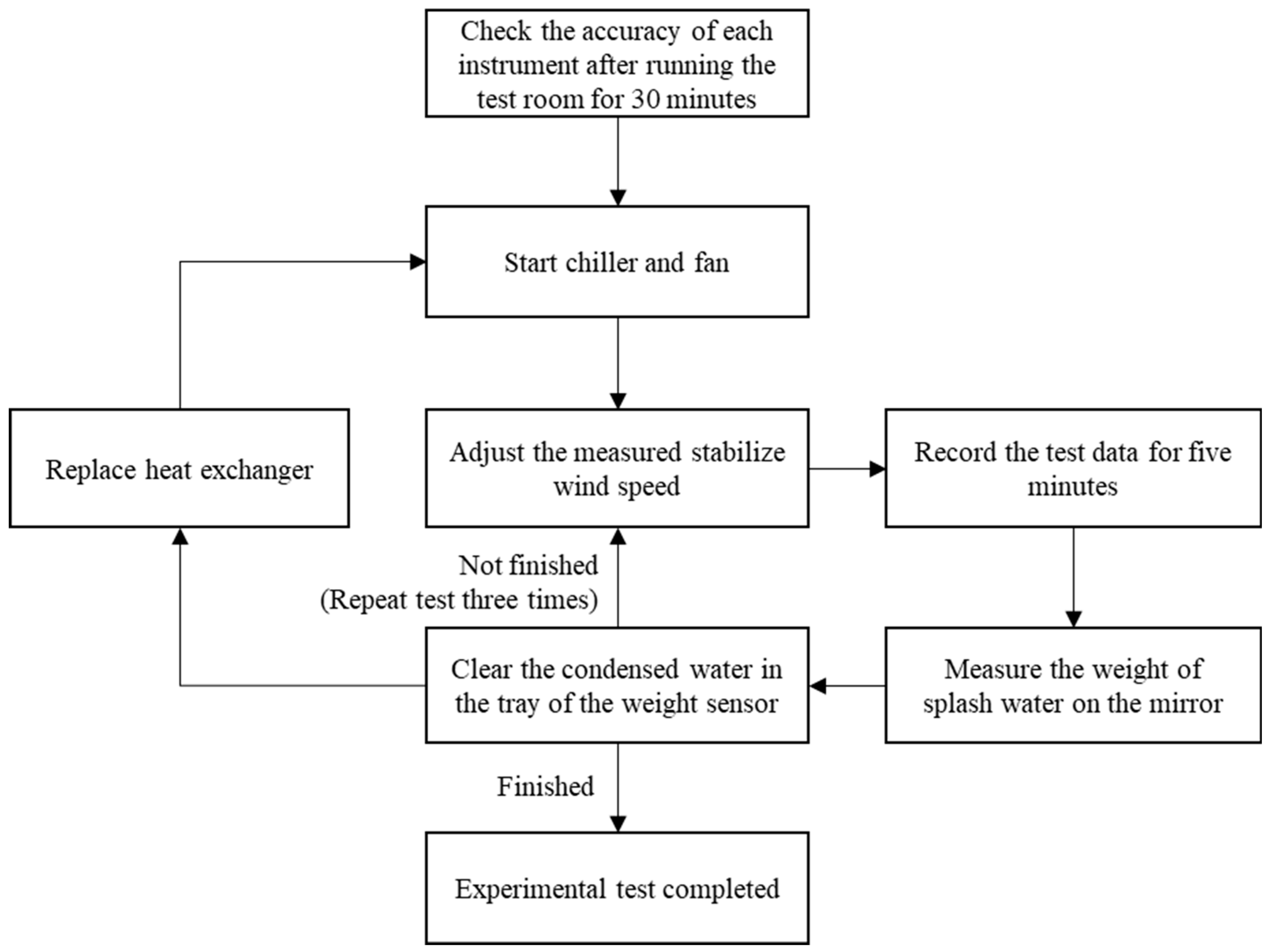
The experimental procedure is illustrated in Figure 5. In the beginning, the test chamber was warmed up for at least 30 min to reach the steady state environmental conditions of 24 ± 0.1 °C/80 ± 2%RH and the steady state inlet chilled water temperature of 7 °C. Then, both the chilled water and the centrifugal fan system were turned on. Afterwards, the airspeed in front of the heat exchanger in the test channel was adjusted to the targeted steady testing speed of 2.5, 3, 3.5, 4, 4.5, and 5 m/s, respectively, by controlling the rotational speeds of the fan. At these air speeds, the maximum turbulence intensity of the flow determined by a hot wire (with an over-heat ratio of 0.7) was about 1.2%. Under these steady conditions, the weight of the condensate splashed and accumulated for five minutes into the water tray was measured. In the process, all the pressures, airspeeds, and temperatures were measured for further analysis. The experiment for each condition was repeated three times to obtain the average results. The experiments were conducted until all of the heat exchangers were tested.

4. Results and Discussion

4.1. Effects of Air Speed on Heat Exchanger Pressure Drops

The effect of airflow speeds on the pressure drops of heat exchangers is depicted in Figure 6. Three trends can be observed. Firstly, the pressure drop increases almost linearly as the airspeed increases, irrespective of surface coating conditions. This is expected due to larger flow frictional resistances at higher speeds. Secondly, a larger fin pitch results in a smaller pressure drop, also irrespective of surface coating conditions; also expected because of smaller geometric constraints on the airflow at larger fin pitches. Lastly, by compared to the uncoated cases, hydrophobic surface coating leads to larger pressure drops; whereas, hydrophilic surface coating leads to smaller pressure drops. Specifically, compared to the uncoated cases, the pressure drops of hydrophilic coated cases can be reduced by about 20–24%, 36–43%, and 43–50% for the fin pitches of 1.5 mm, 2 mm, and 2.5 mm, respectively. This kind of trend was also observed by Ma et al. [3,4]. The pressure drop of the hydrophilic coated surface of pitch 1.5 mm (having the largest fin density of all the cases investigated as listed in Table 1) is still smaller than all of the uncoated cases, indicating the effectiveness of hydrophilic surface coating in reducing the pressure drop of fin-and-tube exchangers by modifying the surface morphology as illustrated in Figure 1. In practical applications, reducing the pressure drop is essential to save fan energy. Even though a lower pressure drop can be obtained by a larger fin pitch, enlarging the fin pitch is not desirable because it will reduce heat transfer due to a smaller FPI. Namely, it would be more practical to lower the pressure drop by surface coating than by enlarging the fin pitch. It should also be cautioned that the hydrophobic surface coating of 1.5 mm in fin pitch results in a considerably larger pressure drop by about 55% to 75% and should be avoided if environmental contamination could lead to hydrophobic surface modifications from the originally uncoated surfaces.

4.2. Effects of Air Speed on Heat Transfer

By referring to ASHRAE Handbook [20], the heat transfer rate of the heat exchanger Q is calculated via Equation (1):
Q = m ˙ × C p × Δ T = V × A v × C p × T o u t T i n
The results are shown in Figure 7. In general, the heat transfer rates increase as the airspeed increases due to faster forced convective heat removal rate by faster-moving air, irrespective of surface coating conditions. On the other hand, the fin pitch effect varies and depends on the surface conditions. For the hydrophilic coating cases, a smaller pitch results in a larger heat transfer as expected due to a larger FPI. But for the uncoated cases, the pitch of 2.0 mm gives the smallest heat transfer rate; whereas, for the hydrophobic cases, the pitch of 2.5 mm gives the largest results. Furthermore, at the pitch of 1.5 mm, the heat transfer rates of the three types of surfaces are comparable. At the pitch of 2.0 mm, the heat transfer rates of both coated surfaces are still comparable and larger than that of the uncoated surface. However, at the pitch of 2.5 mm, in contrast to the largest heat transfer rate of the hydrophobic coated surface, the hydrophilic coated surface results in the smallest heat transfer rate. That is, at this pitch, hydrophobic coating is better than that without coating in heat transfer, consistent with that of Yang et al. [21]. At this larger pitch, water droplets condensed on the surface can be readily blown away from the hydrophobic surface, but not from the hydrophilic surface due to film formation; thus, resulting in the difference. However, even though the hydrophobic surface gives the largest heat transfer rate, the water droplet being carried away by the air could cause undesirable reliability issues of electronic components and systems and should be avoided. Moreover, the hydrophobic coating also results in larger pressure drops as depicted in Figure 6 which lead to larger energy consumption.
In other words, both surface coating and morphology could affect the heat transfer rates and could lead to unexpected results of the fin pitch effect as in the cases of both uncoated and hydrophobic coated surfaces. These unexpected situations deserve further investigation for its clarification and practical applications.
To further examine the behavior of heat exchanger performance, the pressure drops and heat transfer rates described above are non-dimensionalized in terms of Euler number (Eu) [22], Reynolds number (Re), and Nusselt number (Nu) through Equations (2)–(4):
E u = Δ P 1 2 ρ u c 2 N
R e = ρ × V × D μ
N u = h × D k
In the equations, ΔP, ρ, uc, N, V, D, and μ, h, and k represent the pressure drop, air density, velocity in the constriction area, number of tube rows, velocity, characteristic length, air dynamic viscosity, film coefficient, and thermal conductivity, respectively. Physically, the Eu number is the percentage of the flow kinetic energy being lost per fin due to flow resistance (exhibited by the pressure drop); a larger Eu number indicates a larger energy loss. The Re number denotes the relative contribution between the inertial and viscous forces; a larger Re number implies a larger inertial force due to fluid motion. The Nu number represents the relative heat transfer contribution due to fluid motion versus due to fluid conduction; a larger Nu number represents a higher heat transfer rate by the fluid motion. Hence, in practical applications, a smaller Eu number with a larger Nu is typically sought.
By using these non-dimensional parameters, the data scattering is reduced. The results shown in Figure 8 exhibit that as the Re number increases, the Eu number decreases and the Nu number increases as the literature results [23]. It can be observed that the Eu and Nu curves intersect at the Reynolds number around 8000~10,000, 7500~8500, and 6000~10,000 for the uncoated, hydrophilic coated, and hydrophobic coated fin surfaces, respectively. The corresponding air speeds are approximately 3.2 to 4 m/s, 3 to 3.5 m/s, and 2.4 to 4 m/s. The optimum operation conditions are for the Re numbers of about 9000 and 8000 for the uncoated and hydrophilic coated heat exchangers, respectively. In contrast, no clear optimum operation condition can be determined for the hydrophobic heat exchangers. The lower operation Re of the hydrophilic coating indicates its energy-saving capabilities.

4.3. The Effect of Air Speed on Water Splash

The results of splashed water measured are shown in Figure 9, Figure 9a for the overall view whereas Figure 9b–d are locally expanded scales to show the results of uncoated and hydrophilic coating in more detail. Three trends can be observed. Firstly, water splash will occur if the air speed is large enough, irrespective of surface coating conditions. Specifically, the threshold air speeds for water splashing are smaller than 2.5 m/s, about 2.5 m/s, and about 3.0 m/s for the hydrophobic coated, uncoated, and hydrophilic coated fin surfaces. Secondly, water splash of the hydrophobic coated surfaces is the largest, uncoated second, and hydrophilic coated the smallest, for all the fin cases, irrespective of fin pitches and coating conditions. That is, the hydrophilic surface fin coating reduces the amount of splashed water significantly by about one to two orders and about two times with respect to the hydrophobic coated and uncoated surfaces, respectively; thus, it is an effective method of mitigating the water splash situation. Thirdly, critical air speeds for which the amount of water splash increases dramatically exist for both hydrophobic coated and uncoated surfaces, the former being about 3.5 m/s and the latter about 4 m/s. In contrast, for the hydrophilic coated surfaces, no such speed is noticed as the increase is gradual. Hence, by hydrophilic surface coating, the splash amount can be greatly reduced and even completely prevented for smaller air speeds; the result is consistent with those in the literature [8,10,18].
The results of the roughness of about 0.7 µm (Figure 1) and the smaller contact angle of 35° (versus 85°) of the hydrophilic coated fins suggest that that water droplet can sink into the more-or-less uniformly protruded roughness structure of the coated surface. This could lead to two effects. One is the reduced heat transfer capability of the coated surface and the other is the reduced water splash amount. For the pinned water in the submicron structure, heat is transferred mainly by conduction. Thus, the coated fins will transfer heat less effectively because the thermal conductivity of water (about 0.6 W/m-K) is considerably smaller than that of the Al alloy. But this reduced heat transfer can be partially compensated by the enlarged surface area due to roughness. Hence, the overall effect would not be significant as illustrated in this study. In contrast, the pinned water droplet into the coated surface does prevent water splash. Namely, by a thin and rough coating, the reduced heat transfer can be minimized while having enough surface roughness to hold the water droplet for the coating to be effective for practical applications.

5. Conclusions

In this study, the effect of hydrophilic and hydrophobic surface coating on the pressure drop, heat transfer, and water splash of fin-and-tube heat exchangers was examined experimentally. Key observations are as follows.
(1)
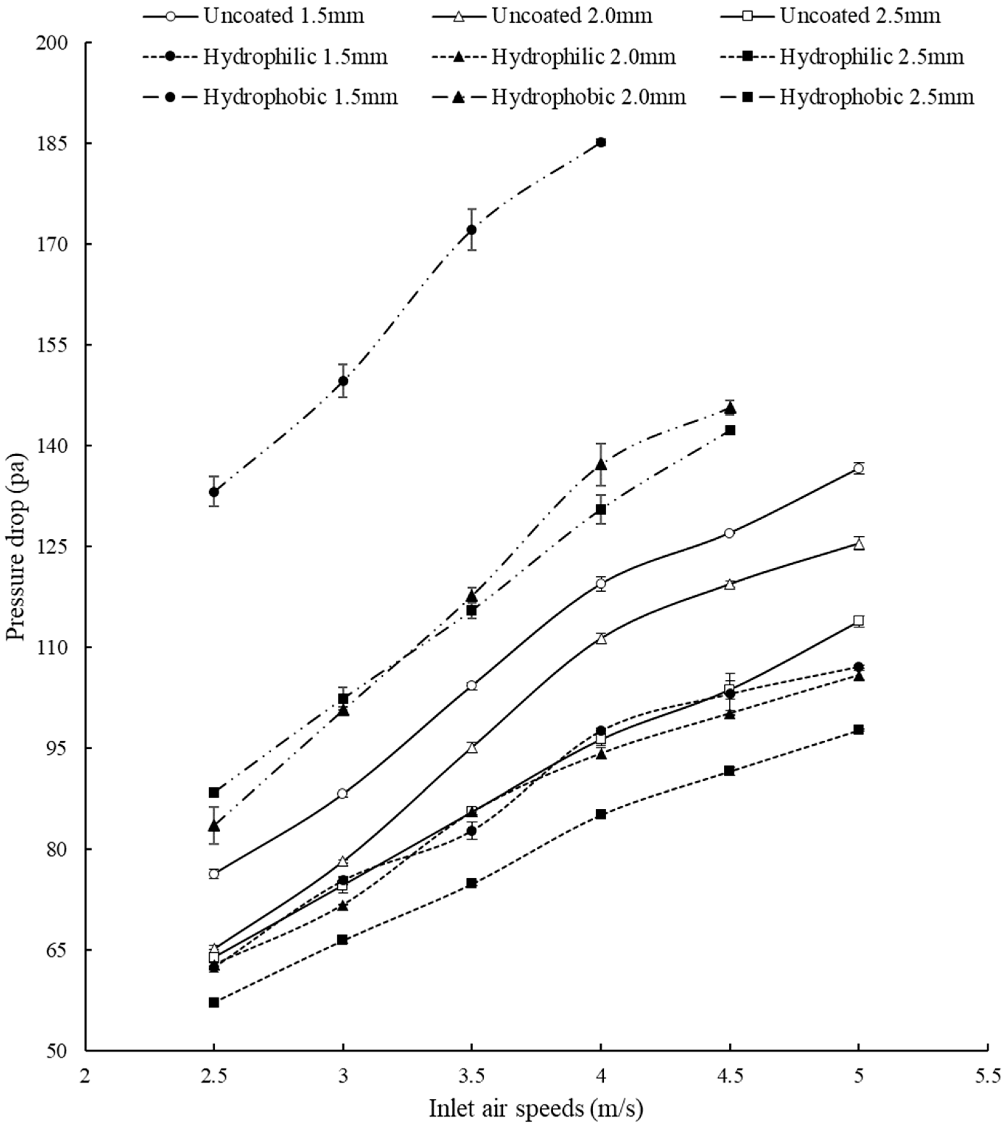
Hydrophilic-coated fins lead to a smaller pressure drop by about 20 to 50% as compared to those of the uncoated cases.
(2)
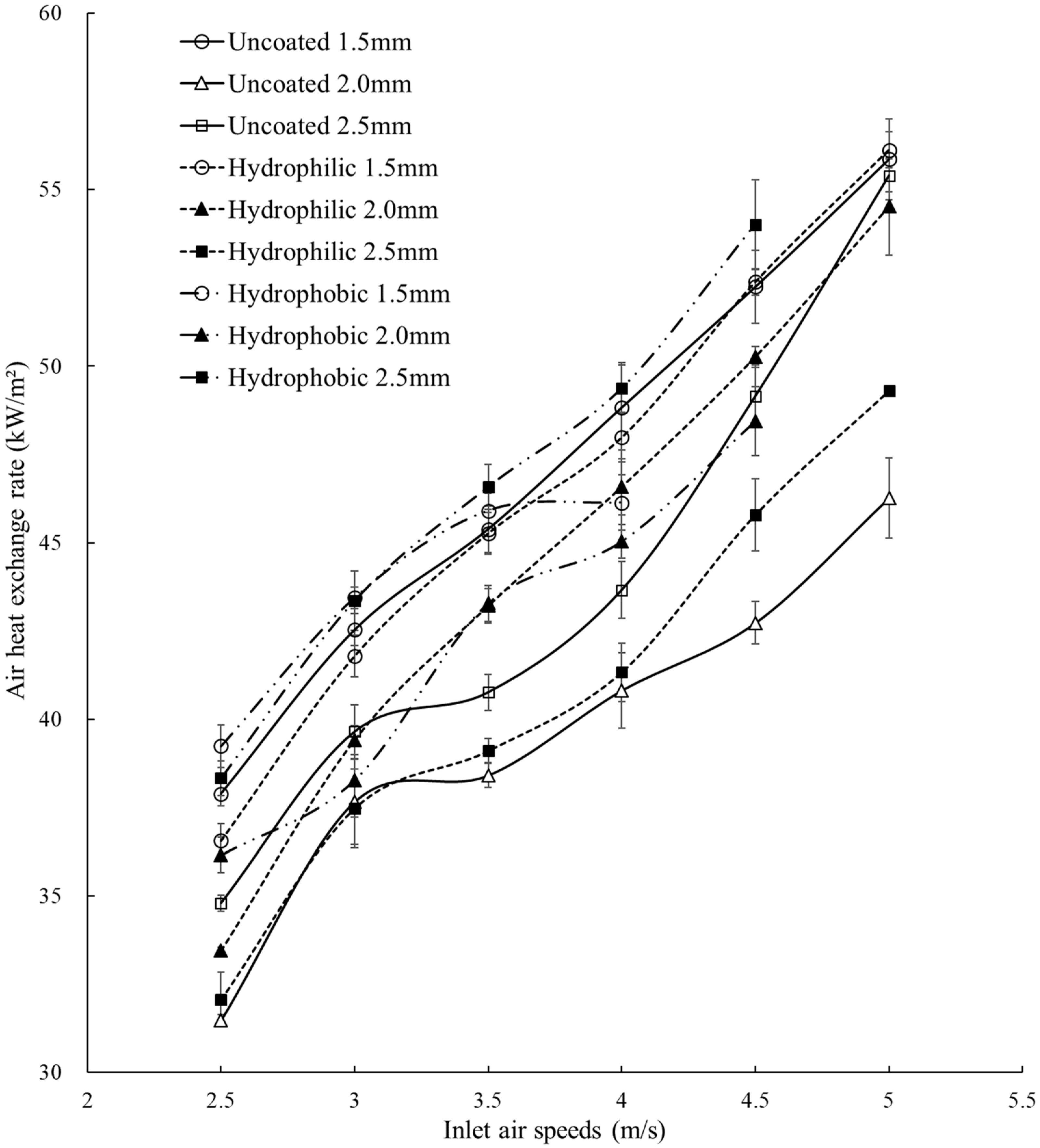
Hydrophilic surface coating also leads to slightly smaller heat transfer rates in reference to the uncoated cases and is insignificant due to thin coating.
(3)
Hydrophilic surface coating is an effective method of mitigating water splash water as the reduction in one to two orders of magnitude and about two times, respectively, with the hydrophobic coated and uncoated surfaces can be achieved. In addition, the threshold splashing speed can be increased from about 2.5 m/s (uncoated) to 3 m/s.
(4)
Hydrophobic surface coating leads to higher pressure drops (about 55 to 75% for the pitch of 1.5 mm) and larger water splash (about one to two orders) and should be avoided.
The present results indicate that hydrophilic surface coating with a thickness of about 5 µm is effective in reducing both water splash and pressure drop while not significantly adversely affecting the heat transfer rate. Thus, the goal of reducing both water splash and energy consumption (by a smaller pressure drop) can be effectively achieved by the hydrophilic surface coating. These findings can be readily applied in industrial HVAC systems to prevent corrosion due to water splash to prolong their lives and also to reduce energy consumption by operating a lower air speed.
On the other hand, the optimum surface condition, the unexpected pitch effect, and the water splash effect on heat transfer were not investigated in this study. These issues can be further researched so that optimum performance for industrial applications can be implemented to utilize energy effectively and reduce carbon emissions. In addition, the corrosion behavior under humid operation can also be studied to enhance the reliability of HVAC systems.

Author Contributions

Conceptualization, J.-S.C.; Methodology, J.-S.C.; Software, J.-S.C.; Validation, J.-S.C.; Formal analysis, J.-S.C.; Investigation, J.-S.C.; Resources, J.-S.C.; Data curation, J.-S.C., S.-Y.C. and C.-C.C.; Writing—original draft, J.-S.C.; Writing—review & editing, J.-S.C.; Visualization, J.-S.C.; Supervision, J.-S.C.; Project administration, J.-S.C.; Funding acquisition, J.-S.C. All authors have read and agreed to the published version of the manuscript.

Funding

This research was funded by the Ministry of Science and Technology, Taiwan, Republic of China, grant number MOST 109-2221-E-017-001.

Conflicts of Interest

The authors declare no conflict of interest.

Nomenclature

ACross-sectional area
CpEqual pressure specific heat
DCharacteristic length
EuEuler number
hConvection coefficient
KConductivity coefficient
NNumber of tube rows
NuNusslet number
QHeat transfer rate
ReReynolds number
TinInlet air temperature
ToutOutlet air temperature
ucVelocity in the constriction area
VVelocity
vSpecific volume
Greek symbols
ΔPPressure drop
θCAContact angle
μDynamic viscosity
ρDensity

References

  1. TIA-942; Telecommunications Infrastructure Standard for Data Centers. ANSI: Washington, DC, USA, 2005; pp. 1–148.
  2. GBT 19413; 2010 Unitary Air-Conditioners for Computer and Data Processing Room. China Machinery Industry Federation: Beijing, China, 2010; pp. 1–18.
  3. Ma, X.; Ding, G.; Zhang, Y.; Wang, K. Effects of hydrophilic coating on air side heat transfer and friction characteristics of wavy fin and tube heat exchangers under dehumidifying conditions. Energy Convers. Manag. 2007, 48, 2525–2532. [Google Scholar] [CrossRef]
  4. Ma, X.; Ding, G.; Zhang, Y.; Wang, K. Airside characteristics of heat, mass transfer and pressure drop for heat exchangers of tube-in hydrophilic coating wavy fin under dehumidifying conditions. Int. J. Heat Mass Transf. 2009, 52, 4358–4370. [Google Scholar] [CrossRef]
  5. Liu, L.; Jacobi, A.M. Air-Side Surface Wettability Effects on the Performance of Slit-Fin-and-Tube Heat Exchangers Operating Under Wet-Surface Conditions. J. Heat Transf. 2009, 131, 051802-1–051802-9. [Google Scholar] [CrossRef]
  6. Wang, C.-C.; Chang, C.-T. Heat and mass transfer for plate fin-and-tube exchangers with and without hydrophilic coating. Int. J. Heat Mass Transf. 1998, 41, 3109–3120. [Google Scholar] [CrossRef]
  7. Hong, K.; Webb, R. Wetting Coatings for Dehumidifying Heat Exchangers. HVAC&R Res. 2000, 6, 229–242. [Google Scholar]
  8. Min, J.; Webb, R.L. Condensate carryover phenomena in dehumidifying, finned-tube heat exchangers. Exp. Therm. Fluid Sci. 2000, 22, 175–182. [Google Scholar] [CrossRef]
  9. Kim, B.; Lee, S.-W.; Ha, S.; Ahn, Y.-C.; Lee, J.K. Characteristic analysis of condensate carry-over according to the surface tensions in the wet and the dry conditions on the fin surfaces of heat exchangers. J. Mech. Sci. Technol. 2006, 20, 1942–1949. [Google Scholar] [CrossRef]
  10. Navarro-Peris, E.; Corberan, J.M.; Gonzalvez, J.; Zamora, M. Analysis of the Condensate Carryover Phenomenon on Fin and Tube Evaporators. Int. J. Air-Cond. Refrig. 2015, 23, 1550008-1–1550008-13. [Google Scholar] [CrossRef]
  11. Qi, B.; Wei, J.; Zhang, L.; Xu, H. A fractal dropwise condensation heat transfer model including the effects of contact angle and drop size distribution. Int. J. Heat Mass Transf. 2015, 83, 259–272. [Google Scholar] [CrossRef]
  12. Zhuang, D.; Hu, H.; Ding, G.; Xi, G.; Han, W. Numerical model for liquid droplet motion on vertical plain-fin surface. HVAC&R Res. 2014, 20, 332–343. [Google Scholar] [CrossRef]
  13. Zhuang, D.; Ding, G.; Hu, H.; Fujino, H.; Inoue, S. Condensing droplet behaviors on fin surface under dehumidifying condition: Part I: Numerical model. Appl. Therm. Eng. 2016, 105, 336–344. [Google Scholar] [CrossRef]
  14. Zhuang, D.; Ding, G.; Hu, H.; Fujino, H.; Inoue, S. Condensing droplet behaviors on fin surface under dehumidifying condition. Part II: Experimental validation. Appl. Therm. Eng. 2016, 105, 345–352. [Google Scholar] [CrossRef]
  15. JIS Z 2371; Methods of Salt Spray Testing. Japanese Standards Association: Tokyo, Japan, 2000.
  16. Stalder, A.F.; Melchior, T.; Müller, M.; Sage, D.; Blu, T.; Unser, M. Low-bond axisymmetric drop shape analysis for surface tension and contact angle measurements of sessile drops. Colloids Surf. A Physicochem. Eng. Asp. 2010, 364, 72–81. [Google Scholar] [CrossRef]
  17. Lu, C.-W.; Huang, J.-M.; Nien, W.C.; Wang, C.-C. A numerical investigation of the geometric effects on the performance of plate finned-tube heat exchanger. Energy Convers. Manag. 2011, 52, 1638–1643. [Google Scholar] [CrossRef]
  18. Kashif, N.; Khan, M.S. Thermal-Hydraulic Performance of Wavy-Fin Heat Exchanger Under Dehumidifying Condition. In USDOE Office of Energy Efficiency and Renewable Energy (EERE); Oak Ridge National Lab: Oak Ridge, TN, USA, 2018. [Google Scholar]
  19. Dehaj, M.S.; Hajabdollahi, H. Fin and tube heat exchanger: Constructal thermo-economic optimization. Int. J. Heat Mass Transf. 2021, 173, 121257. [Google Scholar] [CrossRef]
  20. ASHRAE. ASHRAE Handbook Fundamentals; SI ed Atlanta, Ga; American Society of Heating, Refrigerating, and Air-Conditioning Engineers: New York, NY, USA, 1985. [Google Scholar]
  21. Yang, K.-S.; Lin, H.-Y.; Wu, Y.-L.; Wu, S.-K.; Wang, C.-C. Influence of Surface Modification on the Transient Dehumidification Performance of Fin-and-tube Heat Exchanger. Int. J. Heat Mass Transf. 2021, 173, 121202. [Google Scholar] [CrossRef]
  22. Zukauskas, A.; Ulinskas, R. Banks of plain and finned tubes. In Heat Exchanger Design Handbook; Hewitt, G.F., Ed.; Chapter 2.2.4; Begell House: Danbury, CT, USA, 1998. [Google Scholar]
  23. Ghashim, S.L. New Correlation Equations for Finned Tube Heat Exchangers. J. Eng. Appl. Sci. 2019, 14, 1538–1548. [Google Scholar]
Figure 1. Surface morphology of the fin surfaces. (a) Uncoated surface. (b) Hydrophilic surface. (c) Hydrophobic surface.
Applsci 13 10450 g001
Figure 2. Fin surface contact angle tests. (a) Contact angle (θCA). (b) Contact angle test of uncoated aluminum fin. (c) Contact angle test of hydrophilic aluminum fin. (d) Contact angle test of hydrophobic aluminum fin.
Applsci 13 10450 g002aApplsci 13 10450 g002b
Figure 3. Dimensions of heat exchangers with different fin spacing (unit: mm).
Applsci 13 10450 g003
Figure 4. A schematic diagram of the experimental facility (unit: mm).
Applsci 13 10450 g004
Figure 5. Experimental flowchart.
Applsci 13 10450 g005
Figure 6. Pressure drop for heat exchanger with different fin densities.
Applsci 13 10450 g006
Figure 7. Air heat exchange rates for heat exchanger with different fin densities.
Applsci 13 10450 g007
Figure 8. Distributions of Nu and Eu versus Re. (a) Uncoated heat exchanger; (b) Hydrophilic coated heat exchanger. (c) Hydrophobic heat exchanger.
Applsci 13 10450 g008aApplsci 13 10450 g008b
Figure 9. Effects of fin surface coating on water splash. (a) Splash water of hydrophilic, hydrophobic, and uncoated heat exchangers. (b) Enlarged splashing water situations. (c) Enlarged water splash of uncoated heat exchangers. (d) Enlarged water splash of hydrophilic heat exchangers.
Applsci 13 10450 g009aApplsci 13 10450 g009b
Table 1. Sizes of heat exchanger fins.
Fin Surface PropertiesUncoated Aluminum FinHydrophilic Aluminum FinHydrophobic Aluminum Fin
Pitch (mm)1.522.51.522.51.522.5
Fin thickness (mm)0.10.10.10.10.10.10.10.10.1
Number of fins (piece)97787210777631027463
Number of fins per inch (FPI)16.313.112.118.013.010.617.312.410.7
Heat exchanger height (mm)154154154154154154154154154
Heat exchanger width (mm)170170170170170170170170170
Heat exchanger thickness (mm)383838383838383838
Disclaimer/Publisher’s Note: The statements, opinions and data contained in all publications are solely those of the individual author(s) and contributor(s) and not of MDPI and/or the editor(s). MDPI and/or the editor(s) disclaim responsibility for any injury to people or property resulting from any ideas, methods, instructions or products referred to in the content.

