
Structural Assessment of Endodontic Files via Finite Element Analysis


Abstract
:1. Introduction
2. Materials and Methods
2.1. Description of Physical Tests
2.1.1. ISO 3630-1 Tests
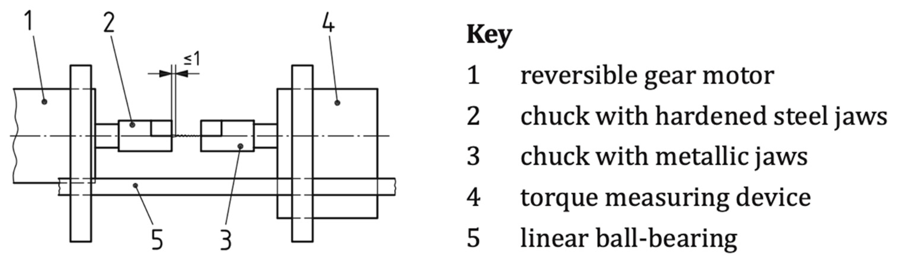
Torsion Tests
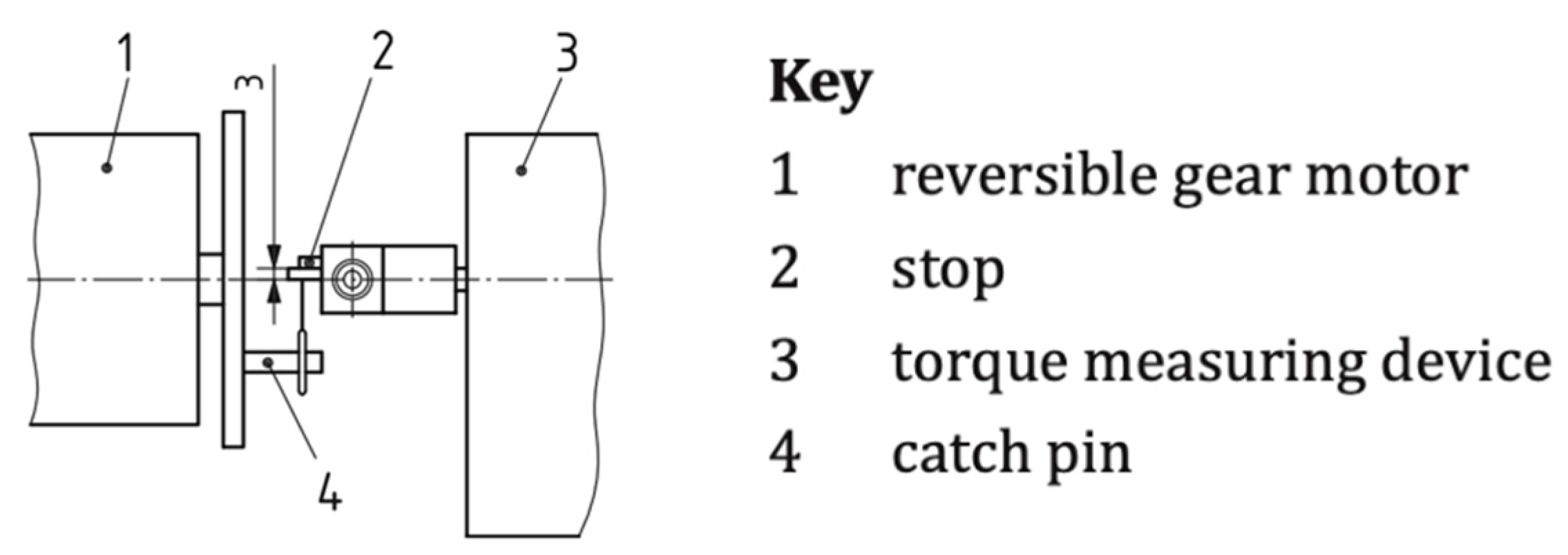
Bending Tests
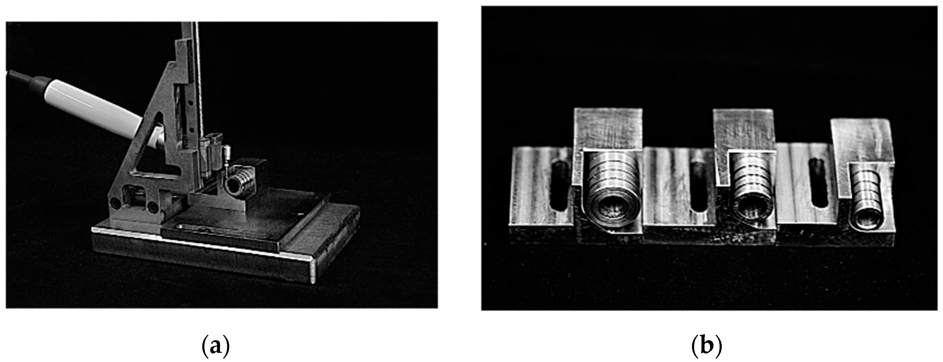
2.1.2. Cyclic Fatigue Tests
2.2. Finite Element Modeling of Physical Tests
2.2.1. Meshing and Solver Convergence Criteria
2.2.2. Finite Element Mesh Development for ProTaper Universal F2 Endodontic File
2.2.3. ISO 3630-1 Test Modeling
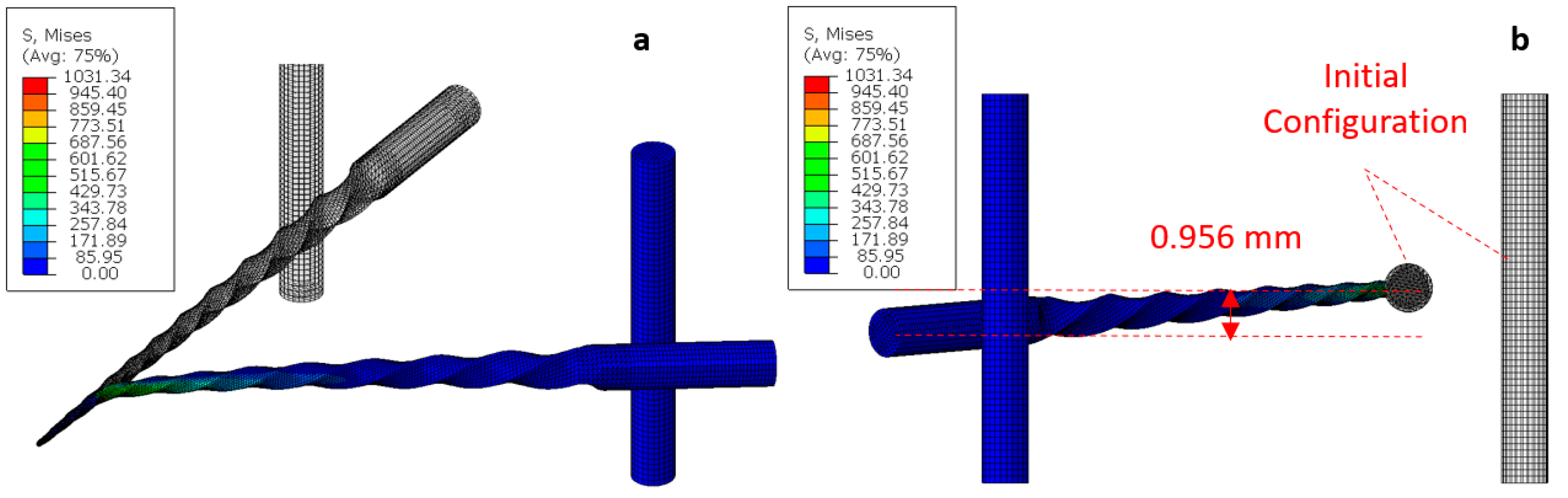
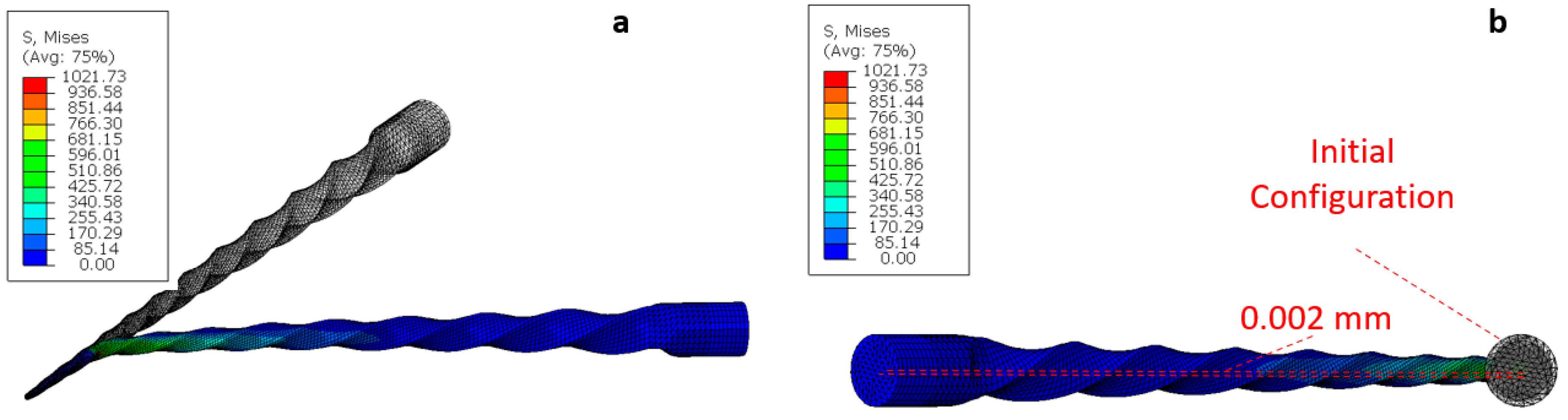
Bending Test Modeling
- Boundary conditions for the high-definition model:
- Boundary conditions for the idealized model
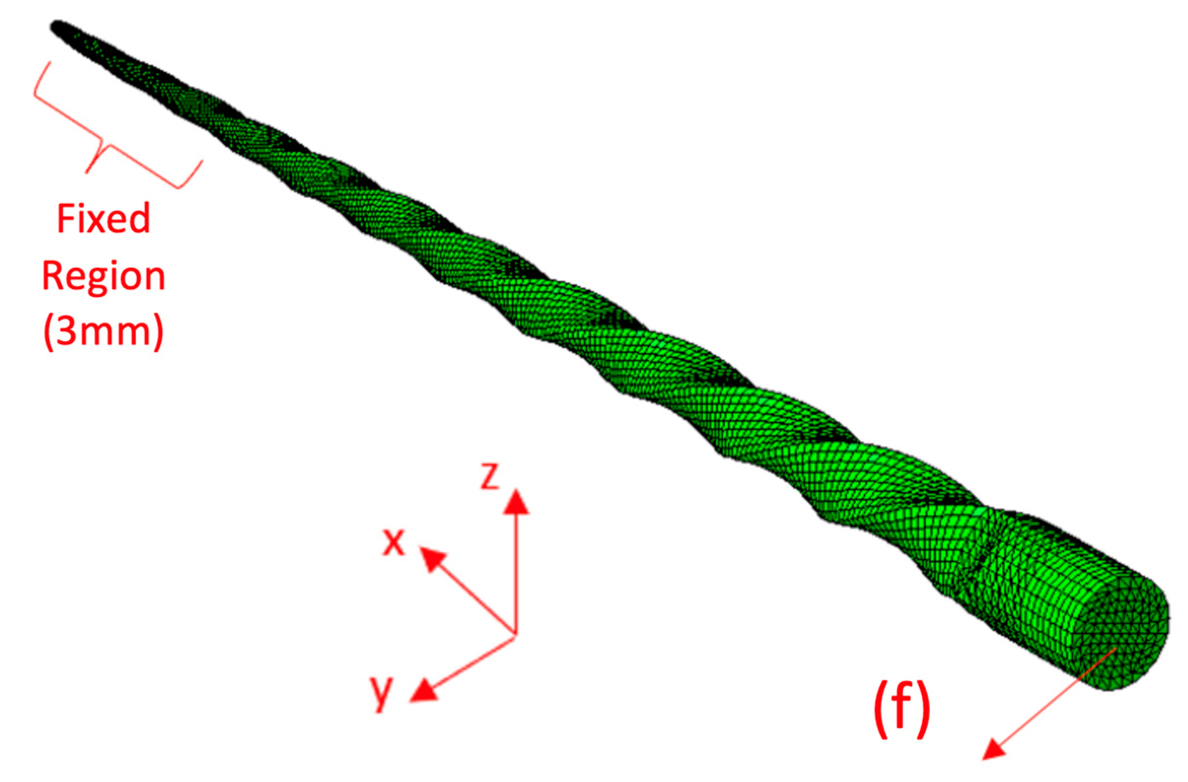
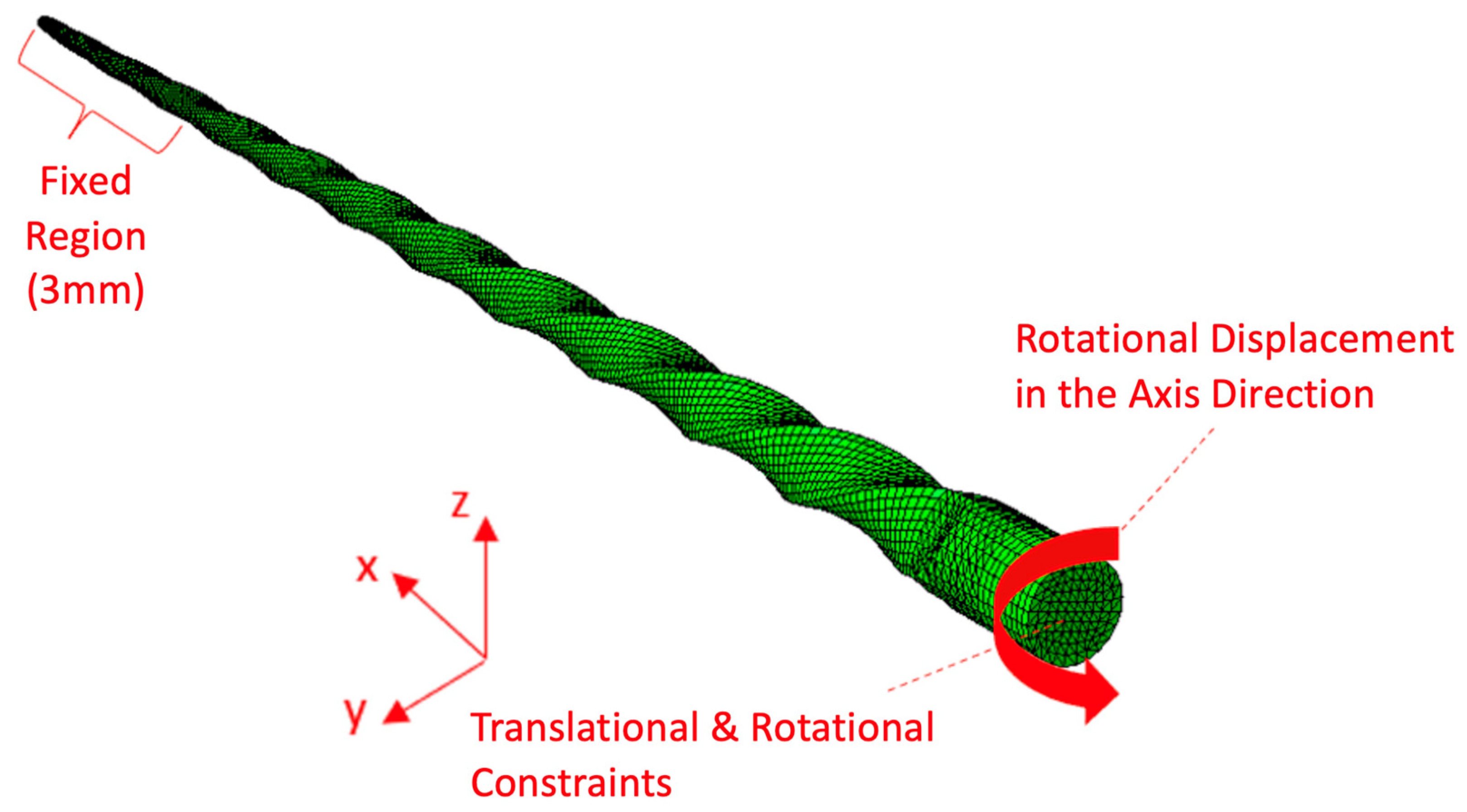
Torsion Test Modeling
- Boundary conditions for the high-definition model
- Boundary Conditions for Idealized model
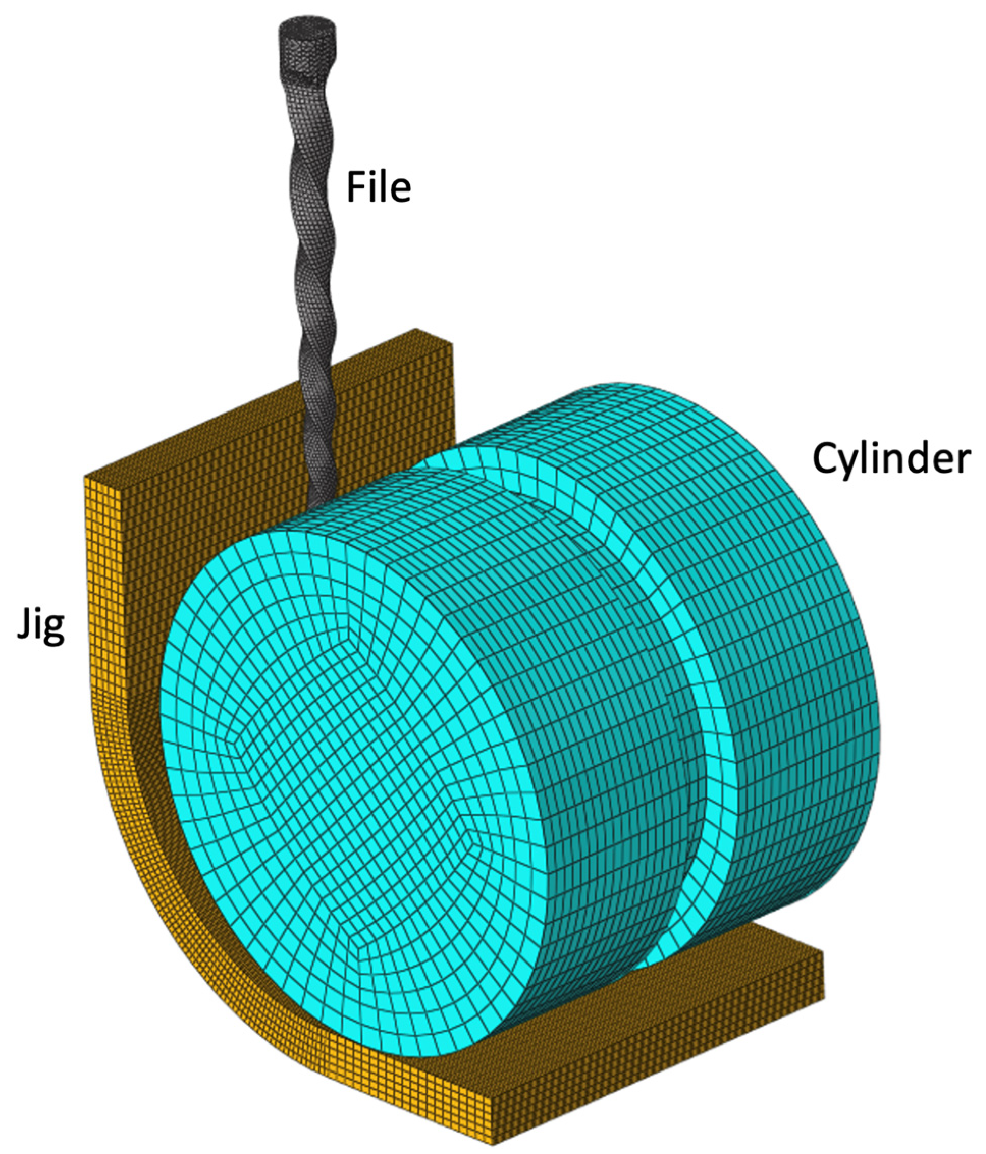
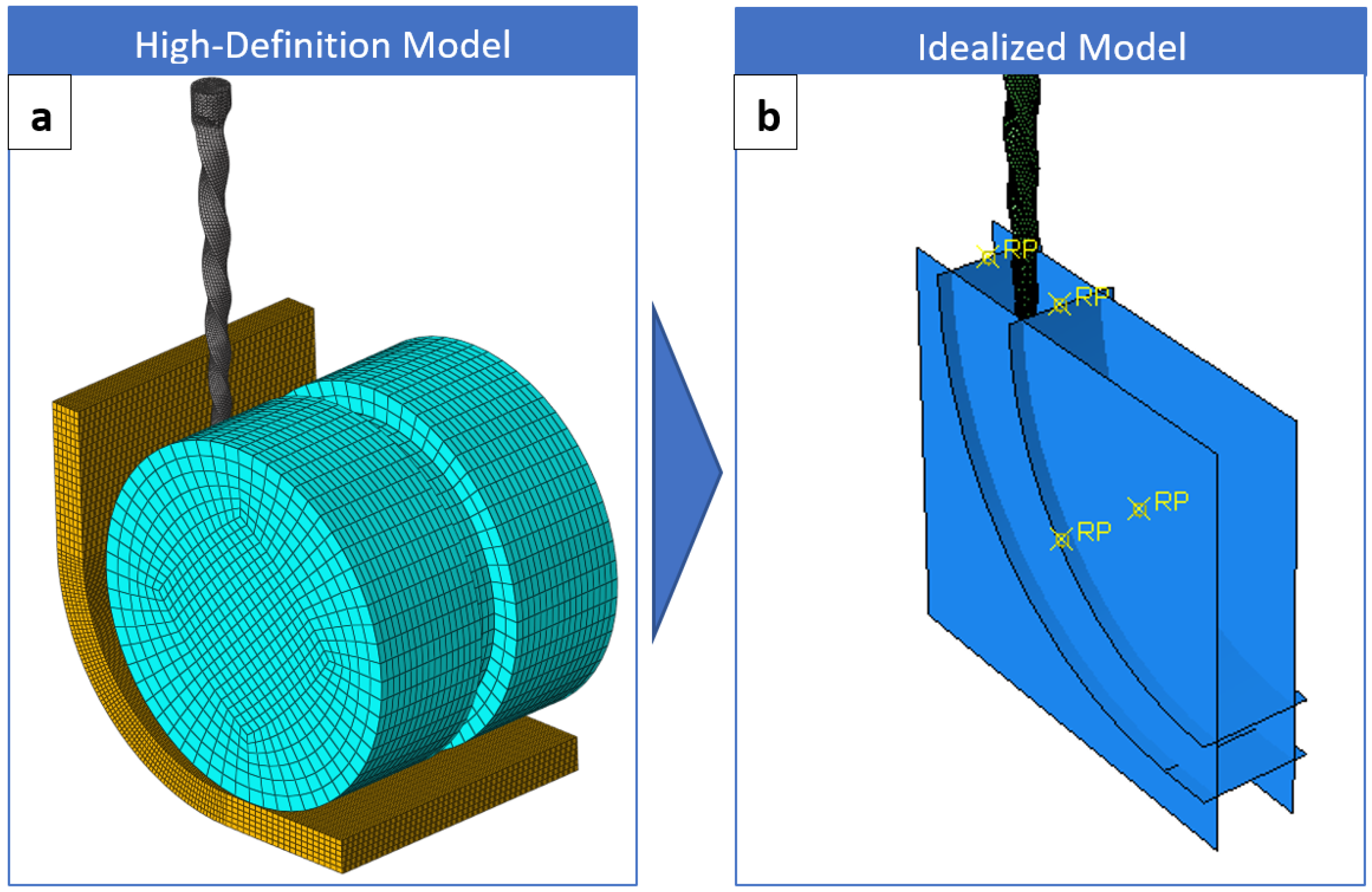
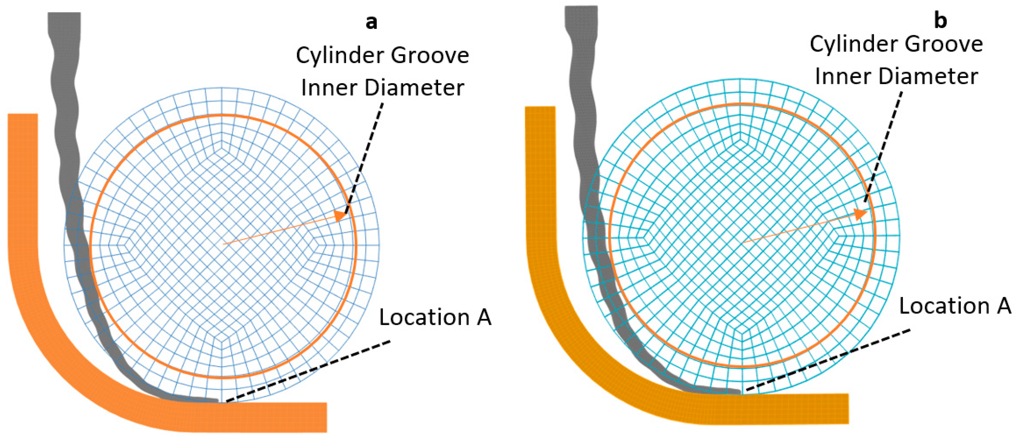
2.2.4. Cyclic Fatigue Test Modeling:
- The high-definition model
- The Idealized model
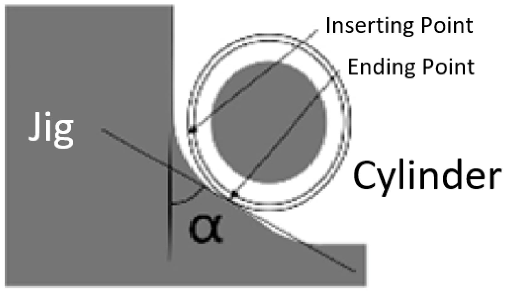
- Endodontic file insertion: The file is inserted to a depth of 22 mm from the top of the jig.
- Endodontic file rotation: After insertion, the file’s axial position is fixed, and it is rotated around its axis until the dissipated energy stabilizes.
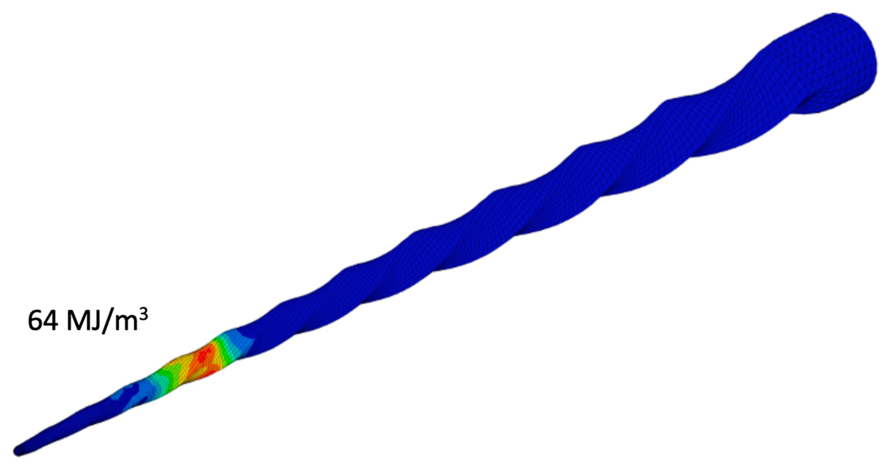
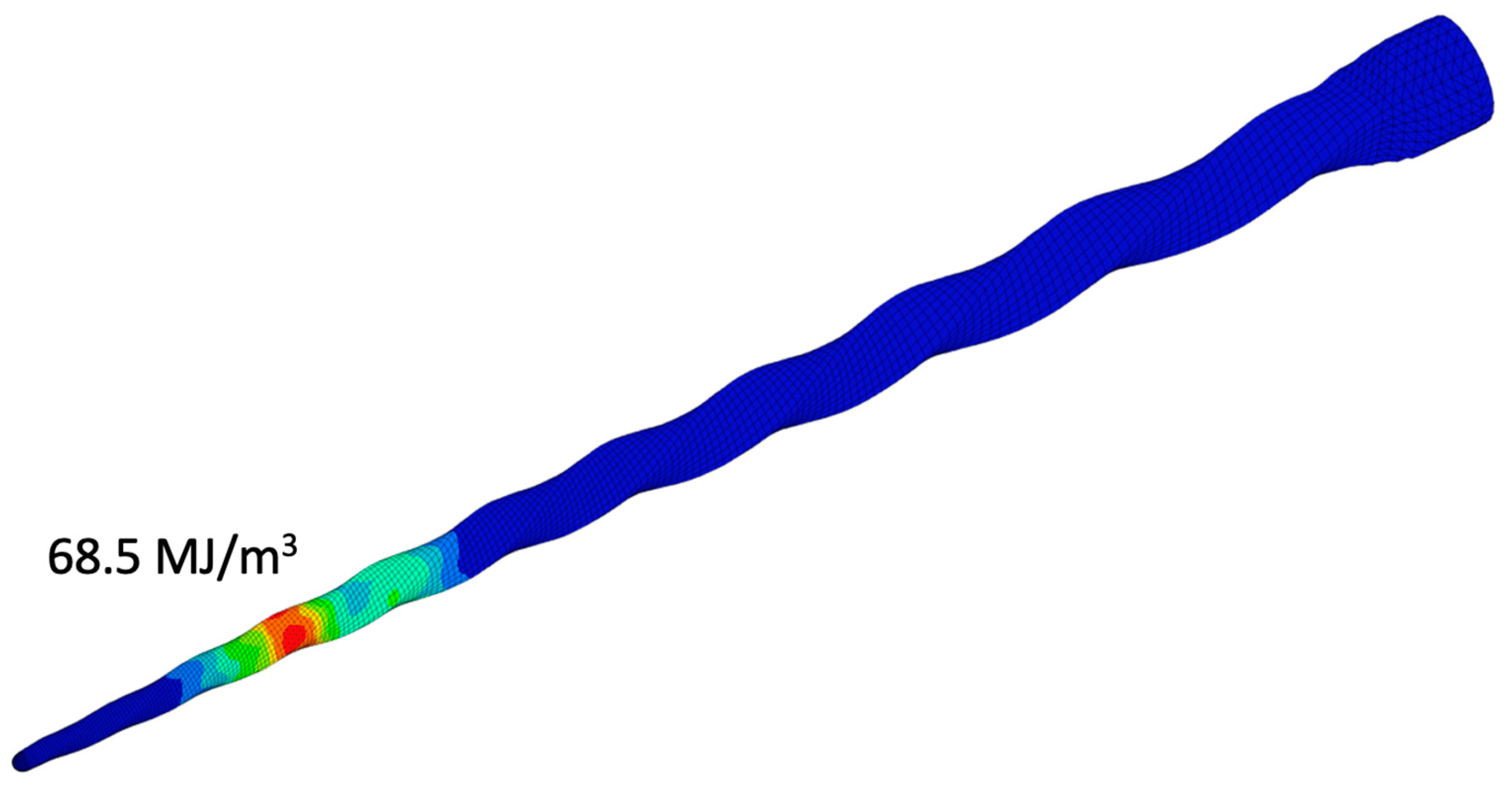
2.2.5. Dissipated Energy Density for Fatigue Life Estimation
3. Results
3.1. ISO 3630-1 Test
3.1.1. Bending Test
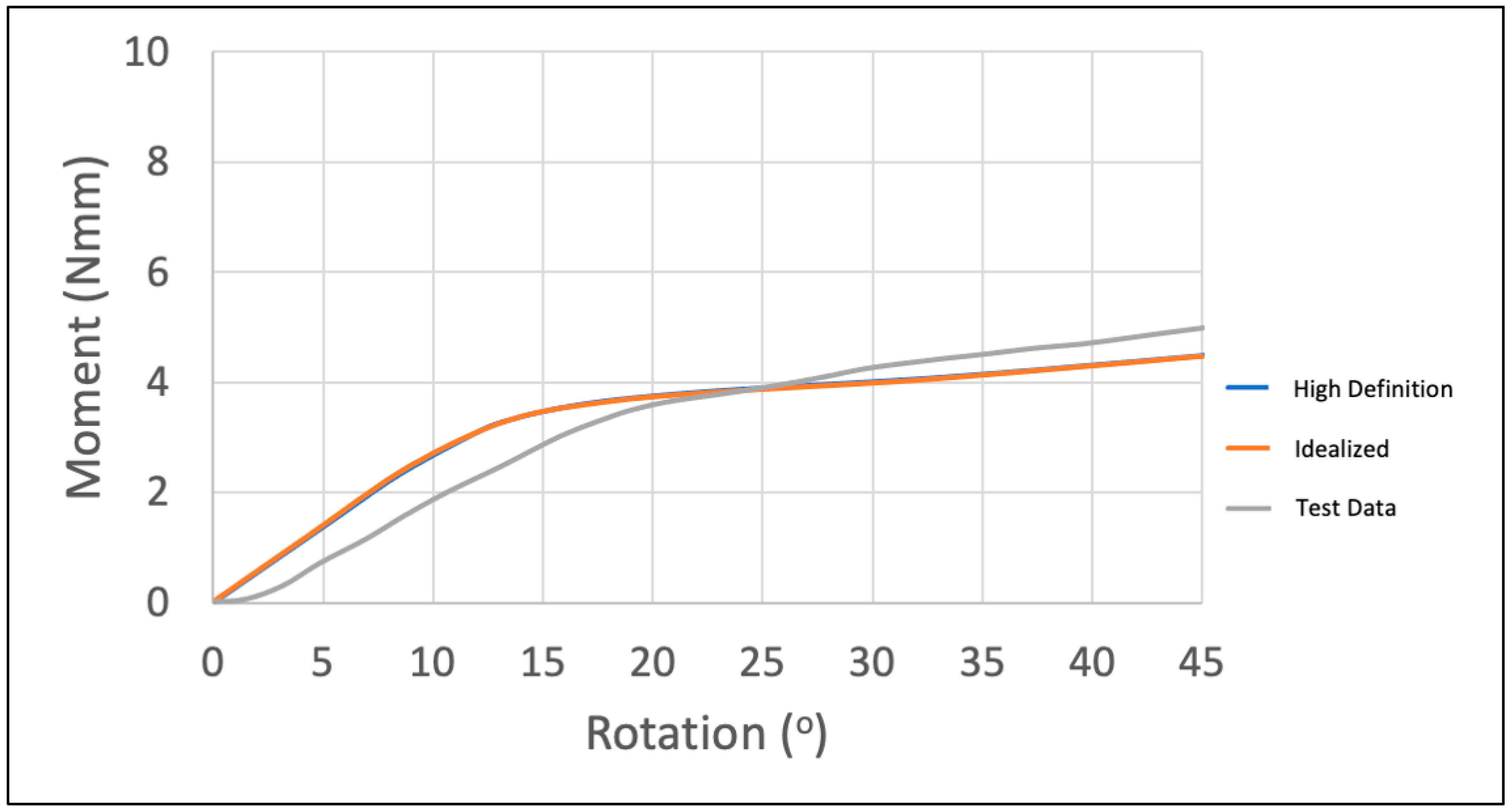
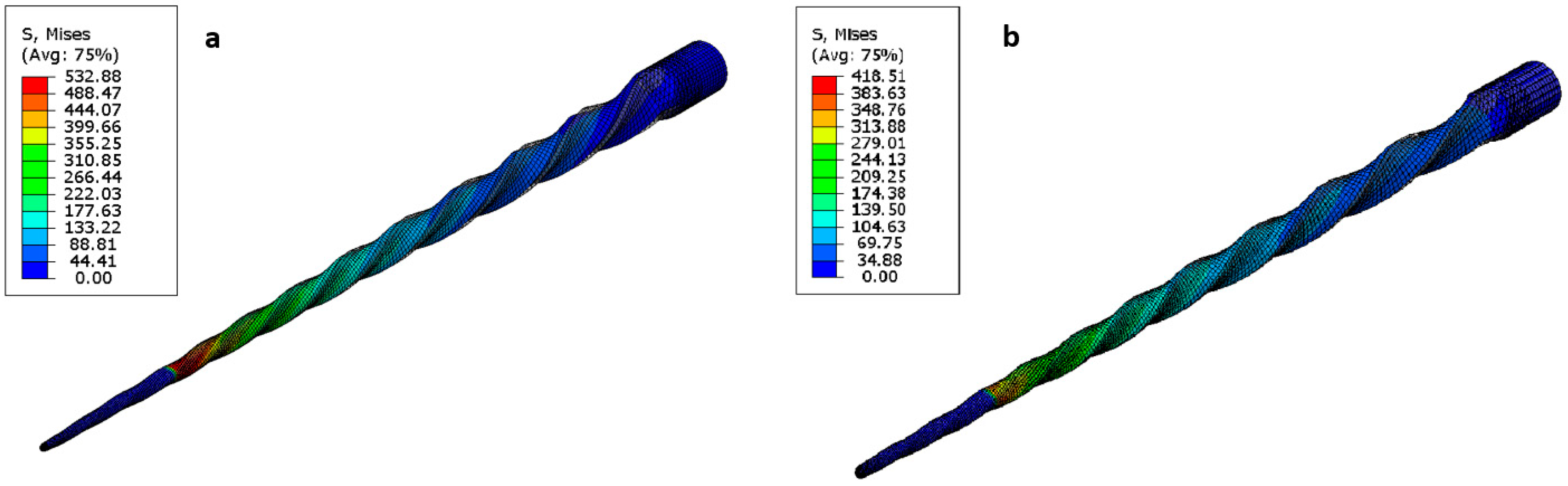
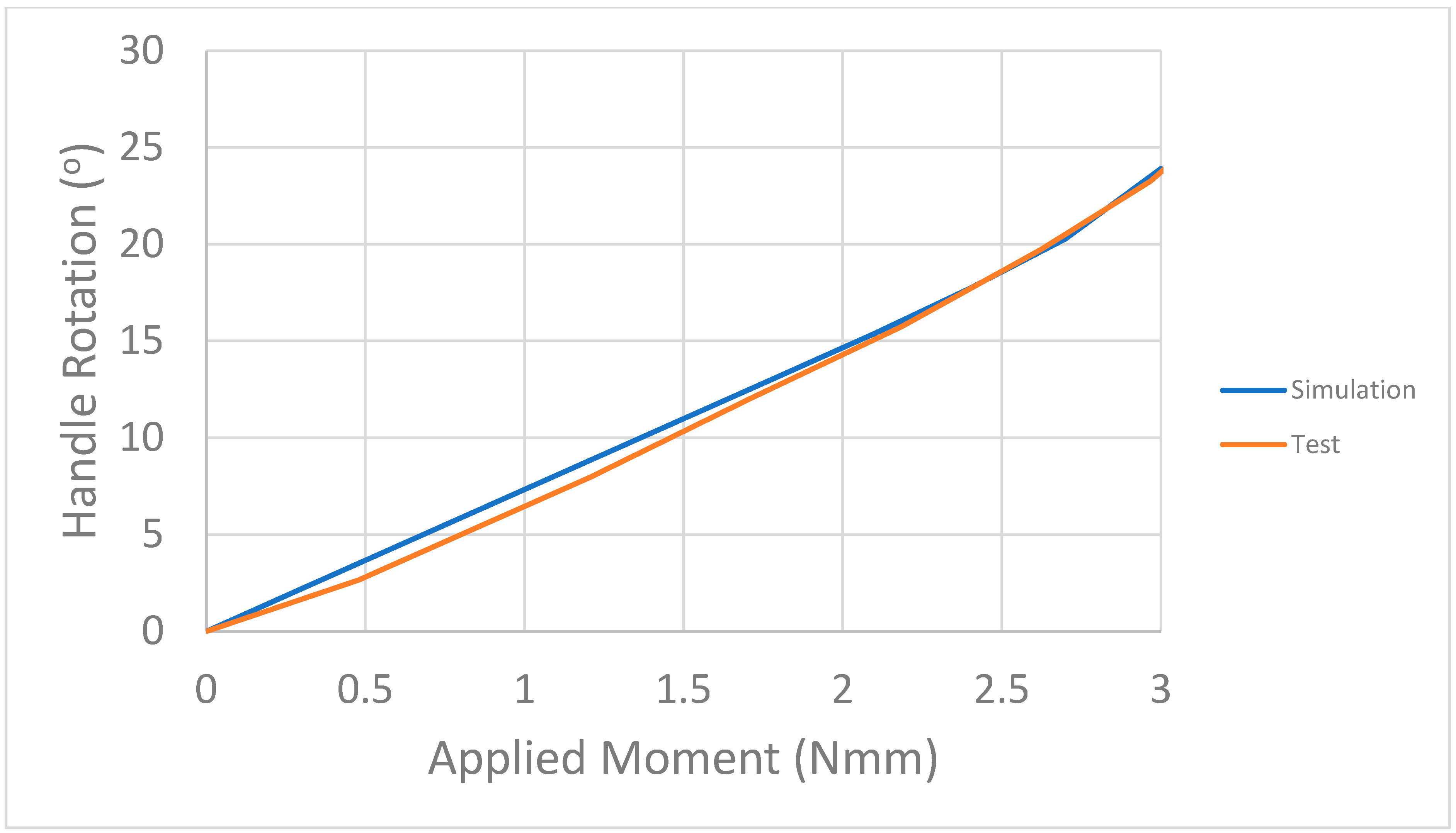
3.1.2. Torsion Test
3.2. Cyclic Fatigue Test
4. Discussion
- ISO 3630-1 Simulations
- Cyclic Fatigue Simulations
5. Conclusions
Author Contributions
Funding
Institutional Review Board Statement
Informed Consent Statement
Data Availability Statement
Acknowledgments
Conflicts of Interest
References
- ISO 3630-1; Dentistry—Endodontic instruments—Part 1: General requirements. International Organization for Standardization: Geneva, Switzerland, 2019.
- Câmara, A.S.; de Castro Martins, R.; Viana, A.C.; de Toledo Leonardo, R.; Buono, V.T.; de Azevedo Bahia, M.G. Flexibility and torsional strength of ProTaper and ProTaper Universal rotary instruments assessed by mechanical tests. J. Endod. 2009, 35, 113–116. [Google Scholar] [CrossRef] [PubMed]
- Vieira, E.P.; Nakagawa, R.K.L.; Buono, V.T.L.; Bahia, M.G.A. Torsional behaviour of rotary NiTi ProTaper Universal instruments after multiple clinical use. Int. Endod. J. 2009, 42, 947–953. [Google Scholar] [CrossRef] [PubMed]
- Savio, F.L.; La Rosa, G.; Bonfanti, M.; Alizzio, D.; Rapisarda, E.; Pedullà, E. Novel Cyclic Fatigue Testing Machine for Endodontic Files. Exp. Tech. 2020, 44, 649–665. [Google Scholar] [CrossRef]
- Gambarini, G. The rationale for the use of low-torque endodontic motors. Endod. Dent. Traumatol. 2000, 16, 95–100. [Google Scholar] [CrossRef] [PubMed]
- Fife, D.; Gambarini, G.; Britto, L. Cyclic fatigue testing of ProTaper NiTi rotary instruments after clinical use. Oral Surgery Oral Med. Oral Pathol. Oral Radiol. Endodontol. 2004, 97, 251–256. [Google Scholar] [CrossRef] [PubMed]
- Whipple, S.J.; Kirkpatrick, T.C.; Rutledge, R.E. Cyclic Fatigue Resistance of Two Variable-taper Rotary File Systems: ProTaper Universal and V-Taper. J. Endod. 2009, 35, 555–558. [Google Scholar] [CrossRef] [PubMed]
- La Rosa, G.R.M.; Shumakova, V.; Isola, G.; Indelicato, F.; Bugea, C.; Pedullà, E. Evaluation of the Cyclic Fatigue of Two Single Files at Body and Room Temperature with Different Radii of Curvature. Materials 2021, 14, 2256. [Google Scholar] [CrossRef] [PubMed]
- Gambarini, G. Cyclic Fatigue of Nickel-Titanium Rotary Instruments after Clinical Use with Low-and High-Torque Endodontic Motors. J. Endod. 2001, 27, 772–774. [Google Scholar] [CrossRef] [PubMed]
- Peng, C.; Hui, W.; Wang, L.; Xin, H.; Deng, S.; Li, C.; Zhang, L. Cyclic fatigue resistance of two nickel-titanium instruments in different curving angles: A comparative study. Braz. Oral Res. 2015, 29, 1–7. [Google Scholar] [CrossRef] [PubMed]
- El-Anwar, M.I.; Yousief, S.A.; Kataia, E.M.; El-Wahab, T.M. Finite element study on continuous rotating versus reciprocating nickel-titanium instruments. Braz. Dent. J. 2016, 27, 436–441. [Google Scholar] [CrossRef] [PubMed]
- de Arruda, S.L.; Lopez, J.B.; de Las Casas, E.B.; de Azevedo Bahia, M.G.; Buono, V.T. Mechanical behavior of three nickel-titanium rotary files: A comparison of numerical simulation with bending and torsion tests. Mater. Sci. Eng. C 2014, 37, 258–263. [Google Scholar] [CrossRef] [PubMed]
- Prados-Privado, M.; Rojo, R.; Ivorra, C.; Prados-Frutos, J.C. Finite element analysis comparing WaveOne, WaveOne Gold, Reciproc and Reciproc Blue responses with bending and torsion tests. J. Mech. Behav. Biomed. Mater. 2019, 90, 165–172. [Google Scholar] [CrossRef] [PubMed]
- Martins, S.C.S.; Garcia, P.R.; Viana, A.C.D.; Buono, V.T.L.; Santos, L.A. Off-Centered Geometry and Influence on NiTi Endodontic File Performance Evaluated by Finite Element Analysis. J. Mater. Eng. Perform. 2020, 29, 2095–2102. [Google Scholar] [CrossRef]
- Lee, M.-H.; Versluis, A.; Kim, B.-M.; Lee, C.-J.; Hur, B.; Kim, H.-C. Correlation between Experimental Cyclic Fatigue Resistance and Numerical Stress Analysis for Nickel-Titanium Rotary Files. J. Endod. 2011, 37, 1152–1157. [Google Scholar] [CrossRef] [PubMed]
- Scattina, A.; Alovisi, M.; Paolino, D.S.; Pasqualini, D.; Scotti, N.; Chiandussi, G.; Berutti, E. Prediction of cyclic fatigue life of nickel-titanium rotary files by virtual modeling and finite elements analysis. J. Endod. 2015, 41, 1867–1870. [Google Scholar] [CrossRef] [PubMed]
- Dassault Systemes, Abaqus Software (Version: 2021) [Computer Software]. 2021. Available online: https://www.3ds.com/support/hardware-and-software/simulia-system-information/abaqus-2021/ (accessed on 4 October 2022).
- Auricchio, F.; Taylor, R.L.; Lubliner, J. Shape-memory alloys: Macromodelling and numerical simulations of the superelastic behavior. Comput. Methods Appl. Mech. Eng. 1997, 146, 281–312. [Google Scholar] [CrossRef]
- Auricchio, F.; Taylor, R.L.; Lubliner, J. Shape-memory alloys: Modelling and numerical simulations of the finite-strain superelastic behavior. Comput. Methods Appl. Mech. Eng. 1997, 143, 175–194. [Google Scholar] [CrossRef]
- Brodie, R. Characterization of Superelastic Nitinol Wire for Application to Aortic Stent Graft Design. Ph.D. Thesis, University of Strathclyde, Department of Mechanical and Aerospace Engineering, Glasgow, Scotland, 2018. [Google Scholar]
- Micro Photonics Inc. (n.d.). NRecon Reconstruction Software (Version: V1.7.4.6) [Computer Software]. Available online: https://www.microphotonics.com/micro-ct-systems/nrecon-reconstruction-software/ (accessed on 8 October 2021).
- Fedorov, A.; Beichel, R.; Kalpathy-Cramer, J.; Finet, J.; Fillion-Robin, J.-C.; Pujol, S.; Bauer, C.; Jennings, D.; Fennessy, F.; Sonka, M.; et al. 3D Slicer as an image computing platform for the Quantitative Imaging Network. Magn. Reson. Imaging 2012, 30, 1323–1341. Available online: https://www.slicer.org (accessed on 4 October 2022). [CrossRef] [PubMed]
- Autodesk. Fusion 360 (Version: V4.11.20210226) [Computer Software]. 2021. Available online: https://www.autodesk.com/products/fusion-360/overview (accessed on 4 October 2022).
- Moumni, Z.; Van Herpen, A.; Riberty, P. Fatigue analysis of shape memory alloys: Energy approach. Smart Mater. Struct. 2005, 14, S287–S292. [Google Scholar] [CrossRef]
- Moumni, Z.; Morin, C.; Zaki, W. Cyclic behaviour and fatigue design of shape memory alloy devices. In Proceedings of the SMST 2010/The International Conference on Shape Memory and Superelastic Technologies, American Society for Metals, 2010. [Google Scholar]
- Gu, X.; Cao, Y.; Zhu, J.; Wang, J.; Zhang, W.; Moumni, Z. Shape optimization of SMA structures with respect to fatigue. Mater. Des. 2020, 189, 108456. [Google Scholar] [CrossRef]


| Austenite Elasticity | 42,530 MPa |
| Austenite Poisson’s Ratio | 0.33 |
| Martensite Elasticity | 12,828 MPa |
| Martensite Poisson’s Ratio | 0.33 |
| Transformation Strain | 10% |
| ) Loading | 6.7 |
| Start of Transformation Loading | 492 MPa |
| End of Transformation Loading | 630 MPa |
| Reference Temperature | 22 °C |
| ) Unloading | 6.7 |
| Start of Transformation Unloading | 192 MPa |
| End of Transformation Unloading | 97 MPa |
| End of Martensitic Elastic Regime | 1200 MPa |
| Quality of Brick and Penta Elements | ||
|---|---|---|
| Warpage | 95% < 40° | 5% < 50° |
| Aspect Ratio | 95% < 10 | 5% < 20 |
| Skew | 95% < 70 | 5% < 80 |
| Minimum angle | >45° (min. 90% > 45° and 10% > 20°) | |
| Maximum angle | <145° (min. 90% < 135° and 10% < 165°) | |
| Jacobian | 95% > 0.4 | 5% > 0.25 |
| Quality of tetra elements | ||
| Tetra Collapse | 0.13 (minimum 95% > 0.3 and 5% > 0.2) | |
| Maximum von Mises Stresses | High-Definition Model | Idealized Model | Difference |
|---|---|---|---|
| PTU F1 | 1031.34 MPa | 1021.73 MPa | 0.9% |
| PTU F2 | 1211.20 MPa | 1239.91 MPa | 2.4% |
Disclaimer/Publisher’s Note: The statements, opinions and data contained in all publications are solely those of the individual author(s) and contributor(s) and not of MDPI and/or the editor(s). MDPI and/or the editor(s) disclaim responsibility for any injury to people or property resulting from any ideas, methods, instructions or products referred to in the content. |
© 2023 by the authors. Licensee MDPI, Basel, Switzerland. This article is an open access article distributed under the terms and conditions of the Creative Commons Attribution (CC BY) license (https://creativecommons.org/licenses/by/4.0/).
Share and Cite
Kökan, E.C.; Atik, A.Y.; Özüpek, Ş.; Podnos, E. Structural Assessment of Endodontic Files via Finite Element Analysis. Appl. Sci. 2023, 13, 10293. https://doi.org/10.3390/app131810293
Kökan EC, Atik AY, Özüpek Ş, Podnos E. Structural Assessment of Endodontic Files via Finite Element Analysis. Applied Sciences. 2023; 13(18):10293. https://doi.org/10.3390/app131810293
Chicago/Turabian StyleKökan, Eyüp Can, Abdulkadir Yasin Atik, Şebnem Özüpek, and Evgeny Podnos. 2023. "Structural Assessment of Endodontic Files via Finite Element Analysis" Applied Sciences 13, no. 18: 10293. https://doi.org/10.3390/app131810293