Article

Simulation and Experiment Study on Cone End Billet Method in Upsetting Billet with a Large Height-to-Diameter Ratio

1
School of Mechanical and Power Engineering, Henan Polytechnic University, Jiaozuo 454000, China
2
The Institute of Seawater Desalination & Multipurpose Utilization, MNR, Tianjin 300192, China
*
Author to whom correspondence should be addressed.
Appl. Sci. 2023, 13(17), 9523; https://doi.org/10.3390/app13179523
Submission received: 1 July 2023 / Revised: 31 July 2023 / Accepted: 8 August 2023 / Published: 23 August 2023
(This article belongs to the Special Issue New Insights in Material Forming)

Abstract

:
A novel upsetting method, called Cone End Billet Upsetting (CEBU), is proposed in this paper to control bulging during the upsetting of large height-to-diameter ratio (LHDR) billets. This new upsetting method is mainly characterized by prefabricating a conical shape at the billet end, which aims to reduce the friction effect between the billet end and the anvil. In order to validate CEBU, the metal flow characteristics during upsetting of LHDR billets with traditional upsetting (TU) and CEBU were analyzed and compared by the finite element method. Experiments were also carried out to examine the deformation characteristics and microstructure of pure copper samples. The results show that, compared with TU, CEBU has a great advantage in restraining bulging and enhancing the compaction effect of upsetting. Meanwhile, bulging can be eliminated in CEBU with a 50% reduction ratio. In addition, aided by the cone end, the metal flow is no longer sensitive to the friction effect at the billet end. From the point of view of restraining bulging, a small taper angle is necessary prior to use. Furthermore, to avoid instability deformation, the height-to-diameter ratio of the billet should be below 3.0. CEBU is effective in suppressing the generation of bulging, but it also increases the pre-forming process for the end of the billet. The study on CEBU in this article is under laboratory conditions, and exploring the industrial application of CEBU will be the focus of our future research.

1. Introduction

Lots of metal products are manufactured using plastic forming techniques such as forging and extrusion. Forging involves the pressure processing of metal parts with the aim of obtaining a certain shape, size, and mechanical properties. Upsetting is one of the forging methods, which is highlighted by its high efficiency in compacting [1]. Especially in hot forging, upsetting is able to eliminate internal pores at the billet’s center [2,3]. Currently, upsetting is widely used in metalworking to improve the mechanical performance of metal parts. Although upsetting has shown its advantage in metal forming, several obstacles should be handled in practice. Due to uneven metal flow in upsetting, bulging is formed around the billet’s center. In addition, cracks are peculiarly prone to generating on the bulged billet surface [4,5]. Restraint bulging is always a hot topic in the study of upsetting, especially for billets with a large height-to-diameter ratio (LHDR), which is defined by an LHDR value above 2 in this article.
The mechanism of bulging formation is largely related to the friction behavior between the billet end and the anvil. During the upsetting process, the flow of metal around the end of the billet is restricted by friction, resulting in the formation of a rigid deformation zone in this area. The friction effect seriously affects the forming uniformity [6,7,8], and lots of efforts have been made to explore the friction behaviors between the anvil and billet end. Manisekar [9] studied the effect of frictional conditions on the cold upsetting of square annealed aluminum billets and deduced the friction factors for different lubricants and bulge parameters. Moreover, Ching Lin [10] investigated the variation of the friction coefficient during the upsetting process by means of an inverse algorithm and verified it by the measured load in an upsetting experiment. By means of response surface methodology and a three-level full-factorial design of experiments, Hong [11] performed a general regression model involving both frictional isotropy and anisotropy to predict the plastic deformation of materials after upsetting. Deng [12] also proposed a new friction testing method, the T-shape upsetting–extruding process employing a rectangular blank, for evaluating the friction conditions during the rib–web part-forming process. Tan [13] proposed a dynamic friction model in which friction depends on both the time rate of strain and normal pressure to predict contact stresses in cylinder upsetting. In addition to these, many investigations have proceeded to explore other aspects [14,15,16,17,18].
The height-to-diameter ratio of the billet is another factor that largely affects bulging formation. Wang [19] proposed a thermo-mechanically coupled model to study deformation characteristics in the upsetting of LHDR disk-shaped forgings and the formation mechanism of the laminated crack defect. Additionally, Antoshchenkov [20] simulated upsetting billets with three different height-to-diameter ratios by means of the Simufact Forming software 10.0v. Moreover, through cylindrical upsetting experiments of pure copper, Han [21] examined the influence of specimen size on dry friction in the meso/micro-forming process. Harikrishna [17] also studied the effect of height-to-diameter ratio on the formability of AA2014 cast alloy and optimized process parameters with Taguchi’s optimization technology. In addition to the investigations discussed above, the phenomenon of surface crack generation in upsetting has also been investigated in terms of billet size [22,23,24].
Although the mechanism of bulging has been studied deeply with the efforts of many scholars, a new, revised upsetting method should be proposed technically in terms of manufacturing. Fortunately, several novel upsetting technologies have been invented from the point of view of restraining bulging. Based on the simulation results, Mi [25] identified surface axial stress as a key factor that leads to surface transverse cracks and proposed a new upsetting method involving the design of a slim waist-shaped billet. However, the size of a slim waist should be calculated precisely in advance. By prefabricating the billet end into a concave shape, concave billet upsetting (CBU) [26] is able to effectively reduce the friction effect between the billet and anvil. But the pre-forming of the billet end into a radial concave shape is difficult to implement in practice. Another upsetting method, which was named soft material pad upsetting (SMPU) [27], was chartered by inserting soft metal between the billet end and the anvil to improve forming uniformity in upsetting. Meanwhile, folding upsetting (FU) [28] was proposed by stacking and reversing the ends of two billets in upsetting. SMPU and FU have the benefit of being easy to apply, whereas the billet is prone to instability in the upsetting of the LHDR billet.
As discussed above, lots of efforts have been made in the field of upsetting bulging, both theoretically and practically. However, the proposed disruptive technologies cannot meet the needs of manufacturing in terms of quantity and efficiency. More and better upsetting methods should be invented. In this article, we propose a novel upsetting method named cone end billet upsetting (CEBU) and analyze its deformation characteristics by simulation and experimentation. The aim of this article is to verify the CEBU’s effectiveness in restraining bulging and discuss its advancement compared with the traditional upsetting method. The simulation and experiment results show that CEBU is a promising method for upsetting the LHDR billet.

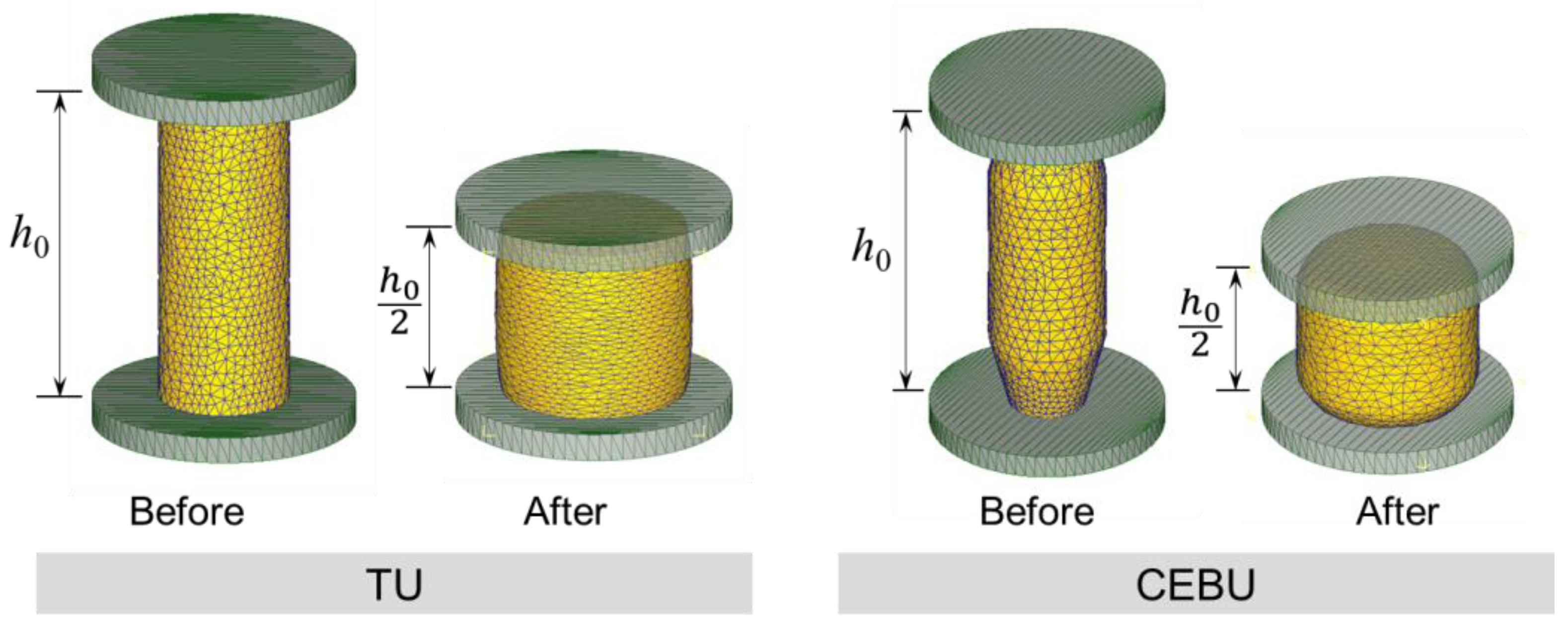
2. Principles of TU and CEBU

CEBU is a novel upsetting method that was developed from the deformation characteristics of traditional upsetting (TU). To highlight the difference between CEBU and TU in upsetting, Figure 1 schematically illustrates the two upsetting methods. The TU is schematically illustrated in Figure 1a. During the upsetting process, due to the friction between the anvil and billet, two large, rigid deformation zones are formed at the billet ends. Meanwhile, outside the rigid deformation zones, the metal flows nonuniformly from the billet inside to its surface. Therefore, due to the non-uniformity of metal flow, buckling will occur and longitudinal cracks may be formed simultaneously on the billet surface.
According to the deformation characteristics of TU, the metal flow around the billet end is a crucial factor that leads to bulging formation. In other words, improving the ability of metal to flow around the billet end is a fundamental way to restrain bulging. CEBU is proposed on the basis of this idea. The principle of CEBU is schematically shown in Figure 1b. By prefabricating a cone shape at the billet end, the contact area between the billet end and the anvil is reduced. Compared with TU, the metal flow in the cone zone is greatly improved, which reduces the influence of the rigid deformation zone at the billet end. In addition, metal flow in the cone part can be considered independent of other parts, resulting in homogeneous deformation in the center section of the billet. As a result, CEBU is able to effectively prevent bulging and longitudinal cracking during upsetting, especially for LHDR billets.
According to Figure 1b, the cone angle α and the height hc are two crucial parameters in CEBU. In practice, for a cylindrical billet, the billet ends should first be tapered. However, a large cone height will result in an excessive overall height of the billet, which is not favorable for upsetting. It is therefore recommended that the height of the cone end be generally less than the diameter of the billet. It should be acknowledged that CEBU adds an end forming process compared to TU. This is a disadvantage when using CEBU in practice.

3. Finite Element Analysis

3.1. Finite Element Analysis Model

In order to investigate the deformation characteristics of CEBU, finite element analysis was carried out in this section. In addition, TU was analyzed using the same method to highlight the development of CEBU. In practice, in order to use CEBU, the cylindrical billet used in TU should first be machined to a conical shape at the billet end. Therefore, in order to compare the differences in metal flow characteristics between TU and CEBU, the billets used in TU and CEBU had the same volume. In other words, the billets used in CEBU are processed from the billets used in TU. Meanwhile, the same reduction ratio, which is represented by the ratio of the initial and final height of the billet in the upsetting process, was used at 50% in TU and CEBU. According to Figure 1, the parameters of the analysis modes are listed in Table 1.
All simulations were performed using the commercial finite element software DEFORM-3D 6.1v. The assembled and meshed models before and after upsetting are shown in Figure 2. In each model, the bottom anvil was fixed, and the top anvil was set to move perpendicularly to the bottom anvil at a constant speed of 1 mm/s. The shear friction model was used to describe the friction behavior between the billet end and the anvil, and its friction coefficient was 0.12. All the anvils were set as rigid bodies, which means that no deformation would occur in the anvils during upsetting. This is generally acceptable because the billet is much softer than the anvil. The material of the billet is T2-copper, which is an industrial pure copper. The simulations were carried out at room temperature. An elastic-plastic material model was applied to the billets. In addition, the Von Mises yield criterion and isotropic hardening model were used. All the billets were divided by tetrahedral meshes. The initial number of meshes was set to 32,000, and the adaptive re-meshing technique was used in the simulation.

3.2. Simulation Results and Discussion

It is generally accepted that the deformation characteristics of the workpiece can be reflected by grid variation in finite element analysis. Accordingly, the simulation results of mesh variation on the billet symmetry plane under TU and CEBU are shown in Figure 3. Due to the friction effect at the billet end, the grids flow downwardly and radially in TU, which leads to bulging generated at the billet center. Meanwhile, the size of the bulge increases as the upsetting progresses. In CEBU, however, the deformation is initially concentrated at the cone end, and the frictional effect at the billet center is largely dispersed. Correspondingly, the bulging is first formed at the bottom of the cone end, and then disappears when the reduction ratio reaches 50%. Compared to TU, CEBU achieves a much smaller bulge.
The variation of equivalent strain on the billet symmetry plane during upsetting is shown in Figure 4. At the beginning of upsetting, the strain is mainly concentrated at the billet ends and is radially distributed in CEBU. However, a more uniform strain field is generated in TU due to a higher friction effect on the billet ends. When the reduction ratio reaches 25%, three characteristic deformation zones have been formed in TU, which are the billet end, the billet lateral surface, and the billet center. Correspondingly, two fan-shaped high-strain zones are formed at the billet ends in CEBU. As the reduction progresses, the two fan-shaped strain zones move closer together, resulting in a large compaction effect at the billet center. In contrast to CEBU, two larger rigid deformation zones are generated at the billet ends in TU, which is the reason for the formation of a small and uniform strain field at the billet center. The results indicate that, compared with TU, much smaller rigid deformation zones can be generated in CEBU. In addition, the compression effect at the billet center is much larger in CEBU than in TU.
Corresponding to the billet radiuses illustrated in Figure 4, the variation of deformation parameters during upsetting is shown in Figure 5. In CEBU, the radius of the billet end, the cone end bottom, and the billet center are taken as the deformation parameters. As shown in Figure 5a, as the reduction ratio increases, the radius of the billet end is first increased linearly and then changed slightly as the reduction ratio increases from 20% to 51%. This is because most of the load is absorbed by the plastic deformation of the billet cone end when the reduction ratio is below 51%. Accordingly, the radius of the billet cone end bottom is greater than that of the billet center. However, when the reduction ratio is above 51%, the radius of the billet center is inversely larger than that of the billet cone end bottom as the reduction ratio increases. The same value can be achieved for the two radiuses when the reduction ratio is 51%, indicating that bulging has been eliminated. As shown in Figure 4, the difference between r1 and r2 can be treated as a bulging index. The results of the bulging index variation with the reduction ratio in TU and CEBU are proposed in Figure 5b. It clearly shows that the bulging size can increase as the reduction ratio improves in TU. However, in CEBU, the bulging is first formed at the cone end bottom and then at the billet center. In addition, the bulging size in CEBU is smaller than that in TU at the same reduction ratio. Compared with TU, CEBU is not only good at restraining bulging but also has a higher compaction effect at the billet center. Meanwhile, CEBU can eliminate bulging at a reduction ratio of 51%. CEBU shows its superior ability to restrain bulging in the upsetting of LHDR billets.
The results of deformation damage after upsetting are shown in Figure 6. It can be seen that the damage in TU tends to occur in the bulging regions. However, in CEBU, the damage is concentrated in the turning area of the cone end, and the magnitude of the damage in CEBU is larger than that in TU. In industrial production, the deformation-damaged parts are usually cut from the billet. This indicates that, compared with TU, CEBU is able to increase the material utilization rate.

4. Validation Experiment

4.1. Experimental Procedure

Experiments were carried out in this section to verify the results of the finite element analysis. In accordance with the conditions of the finite element models, test samples were made of T2 copper bars. A cylindrical sample was prepared for use in TU, and another cylindrical sample with two cone ends was well fabricated as the billet used in CEBU. The samples used in CEBU and TU have the same volume, and the geometric parameters of the samples were the same as those used in the finite element analysis. Figure 7 shows the two types of samples used in the upsetting tests.
Prior to upsetting, all the samples were annealed at 400 °C for 120 min to eliminate internal stress. The same reduction ratio of 50% was used for TU and CEBU. Accordingly, the reduction of TU and CEBU is 31.25 mm and 41.25 mm, respectively. All the upsetting tests were carried out using a hydraulic press with a maximum pressure of 50 tons.
After upsetting, all the samples were cut along their axial direction using an Electric Spark Cutting Machine. The cut section was polished carefully to meet the requirements of crystal phase observation and corroded by FeCl3 + HCl + H2O solution. All the samples were then washed with anhydrous ethanol and water, followed by heat drying with a hair dryer. The microstructure of the samples was observed using a CMM-20 optical microscope. The hardness tests were also carried out after the microstructure observation. The zones for microstructure observation and hardness testing on the cutting section of the samples are shown in Figure 7.

4.2. Experimental Results and Discussion

The shape of the samples after upsetting is shown in Figure 7. It can be seen that bulging has obviously formed on the TU sample. Meanwhile, the surface of the TU sample is rough, which indicates poor uniformity of metal flow during upsetting. In contrast, the CEBU sample does not show any bulging. In addition, the surface of the CEBU sample is much smoother than that of the TU sample, indicating that more uniform metal flows have been formed in CEBU. It must be admitted that the shapes of the two deformed samples in CEBU and TU are different from the finite element analysis. This is mainly due to the ideal friction boundary conditions used in the FEA. In the experiments, the friction conditions at the billet end were affected by the deformation process. Nonetheless, the CEBU showed advantages over the TU in terms of both bulging control and deformation uniformity.
The microstructure in the detection zones of the samples is shown in Figure 8. Using the open-source image processing software ImageJ 1.53v, the average size of the grains in these detection zones can be obtained. For TU, the average grain sizes in the detection zones 1, 2, and 5 were 78.4 μm, 56.2 μm, and 51.6 μm, respectively. In contrast, the average grain sizes of these regions in the CEBU are 62.3 μm, 53.4 μm, and 49.7 μm. The results show that the grain size obtained with CEBU is smaller than that obtained with TU under the same reduction ratio. It is generally accepted that grain size correlates with cumulative plastic strain in metals. Therefore, the grain size results in Figure 8 can indirectly verify the simulation results of the equivalent strain in Figure 4. As discussed in Section 1, due to the friction effect between the billet and the anvil, the metal flow in Zone 1 is restricted. Accordingly, the grain size in zone 1 is generally larger than that in other zones. In relation to the whole billet, the ability of metal flow in CEBU is better than that in TU. As a result, the grain size obtained in CEBU is smaller than that obtained in TU.
In order to further validate the differences in grain size and mechanical properties between CEBU and TU, microhardness tests were carried out. The hardness results at different detection zones of the specimen are shown in Figure 9. It can clearly be seen that the hardness in CEBU is generally higher than that in the corresponding regions of TU. In addition, the highest hardness value is obtained at the center of the CEBU sample. According to the Hall-Patch theory [29], the hardness of a metal is directly related to its grain size. Therefore, the hardness results in Figure 9 are consistent with the microstructure observations in Figure 8. In conclusion, the grain size and hardness results indicate that the use of CEBU not only suppresses the formation of bulging but also results in smaller grain sizes.

5. Influence Factors in CEBU

In this section, the effect of friction coefficient, taper angle of the billet cone end, and height-to-diameter ratio on the deformation characteristics of CEBU was investigated by the finite element method. All the analysis models were established based on the models proposed in Section 2. In addition, corresponding to Figure 4, the difference between r1 and r2 was used as the bulging index.

5.1. Friction Coefficient

The friction coefficient is broadly defined as the frictional effect at the billet end during upsetting. It is generally accepted that a higher friction coefficient will result in a larger bulge during upsetting. The effect of the friction coefficient on the equivalent strain and bulging index is shown in Figure 10. It is impressive to note that the bulging in CEBU is not sensitive to the friction coefficient, even when a high friction coefficient of 0.7 is used. By increasing the friction coefficient, the area of the rigid deformation zone is enlarged. However, due to the advantage of metal flows at the cone end, the influence of the rigid deformation zone on the deformation is very small. In addition, bulging can be eliminated when the reduction ratio reaches about 50%.

5.2. Taper Angle of the Billet Cone End

The influence of the billet end taper angle on the deformation characteristics of CEBU is shown in Figure 11. As the taper angle increases, the metal flow becomes more concentrated around the billet cone end. Meanwhile, at the same reduction ratio, the size of the bulging is increased and the compacting effect on the billet center is decreased. However, the reduction ratio that achieves the bulging elimination is kept almost constant during the variation of the taper angle. From the point of view of achieving a higher compaction effect on the billet center and restraining bulging, it can be concluded that a smaller taper angle is much better to use in the CEBU.

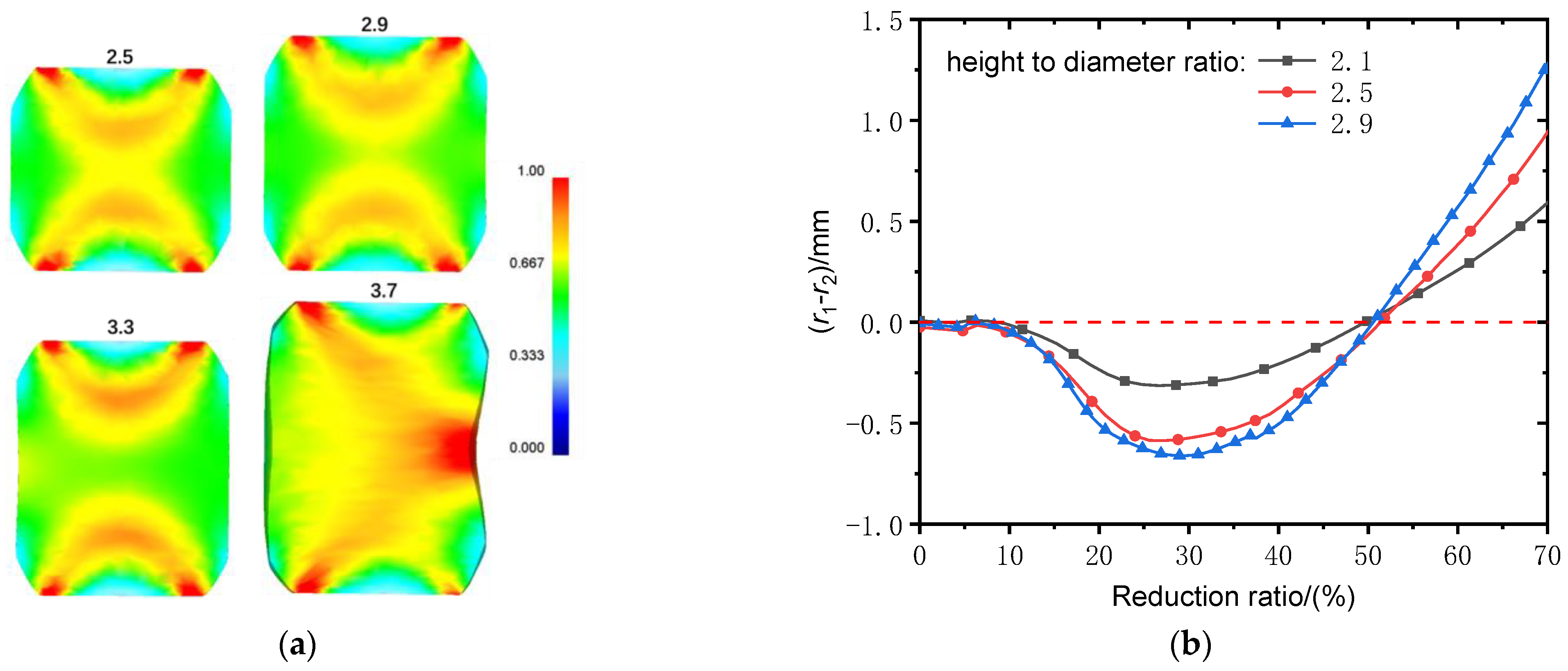
5.3. Height-to-Diameter Ratio

The height-to-diameter ratio (HDR) is a key factor in defining the LHDR billet. Figure 12 shows the effect of HDR on the deformation characteristics of samples in CEBU. It is clearly shown that the compacting effect on the billet center is reduced as the HDR increases. This is because the compacting of the billet center is largely related to the two fan-shaped high-strain zones formed at the billet ends. At the same reduction ratio, a similar-sized fan-shaped high-strain zone is formed, which means the distance between the two fan-shaped high-strain zones is larger at a higher HDR. It should be emphasized that the billet would be unsteadily deformed if its HDR was above 3.0. When the HDR is below 3.0, the bulging size increases as the HDR improves. Nevertheless, the bugling can be eliminated at about a 50% reduction ratio at any HDR. The results indicate that CEBU can be effectively used to reduce bulging in billets with HDR below 3.0.

6. Conclusions

In this article, a novel upsetting method named cone-end billet upsetting (CEBU) was proposed with the aim of restraining upsetting bulging in LHDR billet. Finite element analysis and experiments were conducted to compare the deformation behavior between TU and CEBU. Meanwhile, the influence factors of CEBU were examined by simulations. Some conclusions can be drawn from the present study:
(1)
In CEBU, the deformation is more concentrated at the billet cone end, and two fan-shaped high-strain zones are correspondingly generated at the billet ends. With increasing reduction, the two fan-shaped strain zones gradually approach each other, resulting in a large compression effect at the billet center;
(2)
In CEBU, the frictional effect of upsetting is largely dispersed by metal flows around the conical ends of the billet. Compared with TU, CEBU can produce a much smaller rigid deformation zone at the same reduction ratio, resulting in a much smaller bulging;
(3)
Upsetting bulging can be eliminated when the reduction ratio reaches about 50% in CEBU. If the reduction ratio is less than 50%, bulging will occur at the bottom of the billet cone end. However, when the reduction ratio is above 50%, bulging may occur at the billet middle;
(4)
Benefiting from the cone end, the deformation character is not sensitive to the friction effect at the billet end in CEBU. It is much better to use a small taper angle to control bulging and improve the compaction effect at the billet center. In addition, the billet HDR should be less than 3.0 to avoid instability and deformation. Regardless of the different friction coefficients, taper angles, and HDR, bulging can only be eliminated with a 50% reduction ratio.
In summary, CEBU has a major advantage over TU in reducing bulging and improving the compaction effect of upsetting. In addition, CEBU can eliminate bulging with a reduction ratio of 50%. Despite the above advantages, CEBU also has shortcomings compared to TU. CEBU requires the billet end to be tapered prior to upsetting, which is an additional operation compared to TU. In addition, the studies on CEBU in this article were carried out under laboratory conditions. How to use CEBU effectively in industrial production requires further research, which will be the focus of our future work.

Author Contributions

Conceptualization, J.F. and C.W.; Methodology, J.F., W.L. and Z.L.; Validation, J.F. and C.W.; Formal analysis, J.F. and Z.L.; Investigation, J.F., Z.L., W.L. and C.W.; Writing—original draft preparation, J.F. and Z.L.; Supervision, J.F.; Project administration, J.F.; Funding acquisition, J.F. All authors have read and agreed to the published version of the manuscript.

Funding

This research was supported by the National Natural Science Foundation of China (No.51405136), the Young Backbone Teachers Training Program of Henan Polytechnic University (No.2020XQG-01) and Henan Polytechnic University Innovation Team Project (No.T2019-5).

Institutional Review Board Statement

Not applicable.

Informed Consent Statement

Not applicable.

Data Availability Statement

Not applicable.

Conflicts of Interest

The authors declare no conflict of interest.

References

  1. Wang, Z.J.; Cheng, L.D. Experimental research and numerical simulation of the dynamic cylinder upsetting. Mater. Sci. Eng. A 2009, 499, 138–141. [Google Scholar] [CrossRef]
  2. Hamzah, S.; Ståhlberg, U. A study of pore closure in the manufacturing of heavy rings. J. Mater. Process. Technol. 1998, 84, 25–37. [Google Scholar] [CrossRef]
  3. Lee, M.C.; Jang, S.M.; Cho, J.H. Finite element simulation of pore closing during cylinder upsetting. Int. J. Mod. Phys. B 2008, 22, 5768–5773. [Google Scholar] [CrossRef]
  4. Yang, T.-S.; Hsu, Y.-C. Study on the bulging deformation of the porous metal in upsetting. J. Mater. Process. Technol. 2006, 177, 154–158. [Google Scholar] [CrossRef]
  5. Kim, J.H.; Yang, D.Y. An analysis of upset forging of square blocks considering the three-dimensional bulging of sides. Int. J. Mach. Tool Des. Res. 1985, 25, 327–336. [Google Scholar] [CrossRef]
  6. Rao, J.B.; Kamaluddin, S.; Rao, J.A. Deformation behavior of Al-4Cu-2Mg alloy during cold upset forging. J. Alloys Compd. 2009, 471, 128–136. [Google Scholar] [CrossRef]
  7. Joun, M.S.; Lee, H.J.; Lim, S.G.; Lee, K.H.; Cho, G.S. Dynamic strain aging of an AISI 1025 steel coil and its relationship with macroscopic responses during the upsetting process. Int. J. Mech. Sci. 2021, 200, 106423. [Google Scholar] [CrossRef]
  8. Zhu, S.; Zhuang, X.; Zhu, Y.; Zhao, Z. Thickening of cup sidewall through sheet-bulk forming with controllable deformation zone. J. Mater. Process. Technol. 2018, 262, 597–604. [Google Scholar] [CrossRef]
  9. Manisekar, K.; Narayanasamy, R.; Malayappan, S. Effect of friction on barrelling in square billets of aluminium during cold upset forging. Mater. Des. 2006, 27, 147–155. [Google Scholar] [CrossRef]
  10. Lin, Z.-C.; Chen, C.-K. Inverse calculation of the friction coefficient for upsetting a cylindrical mild steel by the experimental load. J. Mater. Process. Technol. 2006, 178, 297–306. [Google Scholar] [CrossRef]
  11. Hong, J.J.; Yeh, W.C. Application of response surface methodology to establish friction model of upset forging. Adv. Mech. Eng. 2018, 10, 1687814018766744. [Google Scholar] [CrossRef]
  12. Deng, L.; Li, X.T.; Jin, J.S.; Wang, X.Y.; Li, J.J. T-shape upsetting–extruding test for evaluating friction conditions during rib–web part forming. J. Mater. Process. Technol. 2014, 214, 2276–2283. [Google Scholar] [CrossRef]
  13. Tan, X. Evaluation of friction in upsetting. Prod. Eng. 2011, 5, 141–149. [Google Scholar] [CrossRef]
  14. Azushima, A.; Yoneyama, S.; Utsunomiya, H. Coefficient of friction at interface of lubricated upsetting process. Wear 2012, 286–287, 3–7. [Google Scholar] [CrossRef]
  15. Tian, B.; Kleber, S.; Schneller, S.; Markiewicz, P. Influencing factors of global and local deformation in hot compression. Procedia Manuf. 2018, 15, 381–387. [Google Scholar] [CrossRef]
  16. Jenner, A.; Bai, Y.; Dodd, B. A shear instability criterion applied to surface cracking in upsetting. J. Mech. Work. Technol. 1981, 4, 369–375. [Google Scholar] [CrossRef]
  17. HariKrishna, C.; Nagaraju, C. Modeling of cylindrical upsetting process for enhanced ductile fracture. Mater. Today Proc. 2021, 39, 1629–1634. [Google Scholar] [CrossRef]
  18. Coppieters, S.; Lava, P.; Sol, H.; Bae, A.V. Determination of the flow stress and contact friction of sheet metal in a multi-layered upsetting test. J. Mater. Process. Technol. 2010, 210, 1290–1296. [Google Scholar] [CrossRef]
  19. Wang, M.; Li, D.; Wang, F. Analysis of laminated crack defect in the upsetting process of heavy disk-shaped forgings. Eng. Fail. Anal. 2016, 59, 197–210. [Google Scholar] [CrossRef]
  20. Antoshchenkov, Y.M.; Taupek, I.M. Computer simulation of axisymmetric upsetting. Steel Transl. 2015, 45, 38–41. [Google Scholar] [CrossRef]
  21. Han, J.; Zheng, W.; Wang, G.; Yu, M. Experimental study on size effect of dry friction in meso/micro-upsetting process. Int. J. Adv. Manuf. Technol. 2018, 95, 1127–1133. [Google Scholar] [CrossRef]
  22. Sljapic, V.; Hartley, P.; Pillinger, I. Observations on fracture in axi-symmetric and three-dimensional cold upsetting of brass. J. Mater. Process. Technol. 2002, 125–126, 267–274. [Google Scholar] [CrossRef]
  23. Arikawa, T.; Yamabe, D.; Kakimoto, H. Influence of anvil shape of surface crack generation in large hot forging process. Procedia Eng. 2014, 81, 480–485. [Google Scholar] [CrossRef]
  24. Zhang, Z.J.; Dai, G.Z.; Wu, S.N.; Dong, L.X.; Liu, L.L. Simulation of 42CrMo steel billet upsetting and its defects analyses during forming process based on the software DEFORM-3D. Mater. Sci. Eng. A 2009, 499, 49–52. [Google Scholar] [CrossRef]
  25. Mi, G.; Zhang, J.; Xu, B.l. Surface stress evolution and cracks prevention of ingots during the upsetting process. Eng. Rev. 2019, 39, 292–301. [Google Scholar] [CrossRef]
  26. Lin, S.Y. Stress analysis of upsetting with concave curve dies. J. Mater. Process. Technol. 2002, 123, 36–41. [Google Scholar] [CrossRef]
  27. Bouchard, P.-O.; Lebret, G.; Hachem, E. Identification of glass pad lubricant viscosity using a trapping thermomechanical test. J. Mater. Process. Technol. 2013, 213, 392–400. [Google Scholar] [CrossRef]
  28. Hong, C.; Leigang, W.; Xigen, Q. Study on forming law in the forging of 06Cr25Ni20 ring billet. Heavy Cast. Forg. 2012, 5, 1–3. [Google Scholar]
  29. Lehto, P.; Remes, H.; Saukkonen, T.; Hänninen, H.; Romanoff, J. Influence of grain size distribution on the Hall-Petch relationship of welded structural steel. Mater. Sci. Eng. A 2014, 592, 28–39. [Google Scholar] [CrossRef]
Figure 1. Schematic of the upsetting process. (a) TU; (b) CEBU.
Applsci 13 09523 g001
Figure 2. Finite element analysis model.
Applsci 13 09523 g002
Figure 3. Variation of the grid on billet symmetry plane (reduction ratio 25%, 50%, 70%).
Applsci 13 09523 g003
Figure 4. Equivalent strain on billet symmetry plane (reduction ratio 5%, 25%, 50%).
Applsci 13 09523 g004
Figure 5. Variation of billet radiuses in upsetting. (a) Billet radiuses of CEBU; (b) comparison between TU and CEBU.
Applsci 13 09523 g005
Figure 6. Distribution of damage after upsetting.
Applsci 13 09523 g006
Figure 7. Samples used in the upsetting test. (a) TU; (b) CEBU.
Applsci 13 09523 g007
Figure 8. Microstructure in detection zones of samples.
Applsci 13 09523 g008
Figure 9. Hardness at the detection zones of the sample.
Applsci 13 09523 g009
Figure 10. Influence of friction coefficient. (a) Equivalent strain (50% reduction ratio); (b) bulging index.
Applsci 13 09523 g010
Figure 11. Influence of the taper angle of the cone end. (a) Equivalent strain (50% reduction ratio); (b) bulging index.
Applsci 13 09523 g011
Figure 12. Influence of height-to-diameter ratio. (a) Equivalent strain (50% reduction ratio); (b) bulging index.
Applsci 13 09523 g012
Table 1. Parameters of finite element analysis models.
CEBUTU
d25 mmd25 mm
h40 mmht62.5 mm
hc16.25 mm
α15°
Disclaimer/Publisher’s Note: The statements, opinions and data contained in all publications are solely those of the individual author(s) and contributor(s) and not of MDPI and/or the editor(s). MDPI and/or the editor(s) disclaim responsibility for any injury to people or property resulting from any ideas, methods, instructions or products referred to in the content.

