Article

Creep Instability Mechanism and Control Technology of Soft Coal Roadways Based on Fracture Evolution Law

1
Key Laboratory of Deep Coal Resource Mining, Ministry of Education, China University of Mining and Technology, Xuzhou 221116, China
2
School of Mines, China University of Mining and Technology, Xuzhou 221116, China
3
Henan Sunho Group Co., Ltd., Yongcheng 476600, China
*
Author to whom correspondence should be addressed.
Appl. Sci. 2023, 13(16), 9344; https://doi.org/10.3390/app13169344
Submission received: 9 July 2023 / Revised: 13 August 2023 / Accepted: 15 August 2023 / Published: 17 August 2023

Abstract

:
To address the challenging issues of large deformation, control difficulties, and susceptibility to failure in the support structure of soft coal roadways, this study utilizes the CVISC block creep model in UDEC software. The model incorporates Coulomb slip without cohesive contact to simulate the characteristics of soft coal, such as its loose, fragile, and small-block nature. Additionally, a soft coal nonlinear discrete element creep model is developed to investigate the creep characteristics of soft coal under triaxial compression, with the aim of revealing the underlying creep destabilization mechanism in soft coal tunnels. Based on the research findings, a primary, strong active support technology is proposed. This approach involves the use of high-preload, high-strength anchor rods and anchor cables, as well as the implementation of steel mesh and plastic woven mesh to enhance surface protection. The study highlights that: (1) The shear cracks inside the coal body of the soft coal specimen transform into tensile cracks under external force, leading to an increase in the number of tensile cracks. This is an important symbol of accelerated creep in soft coal. Improvement in peripheral pressure helps inhibit the generation of tensile cracks inside the specimen. (2) The rapid development of creep and inter-particle tensile fissures within the coal body particles themselves, along with the change in stress state after the excavation of the roadway, are the main reasons for the overall creep damage of the roadway. (3) The support force in the early stage of shed cable support is small, which cannot inhibit the accelerated development of tensile fissures. This leads to continuous deformation of the roadway, resulting in the failure of the support structure in the later stage and aggravated roadway damage. (4) The new support technology helps control surface deformation by enhancing the strength of the roadway protection surface. This suppresses the development speed and number of tensile fissures during roadway deformation, improves the starting strength of the roadway for accelerated creep, and enables effective control of the overall deformation of the soft coal roadway. Thus, the effectiveness of roadway support is remarkable.

1. Introduction

Due to the depletion of easily accessible coal seam resources in China, coal mining operations are increasingly delving into deeper layers, resulting in a more complex mining environment. Consequently, mining becomes more challenging, particularly in terms of roadway support [1,2,3]. Soft coal roadways, characterized by their low strength, soft lithology, and rheological properties, face issues such as supporting structure failures and continuous roadway deformation [4]. Given the phenomenon of creep instability in soft coal roadways, it becomes imperative to comprehend the mechanisms underlying roadway instability and propose appropriate support measures in response to roadway deformations. Therefore, a comprehensive study of the creep characteristics of soft coal, the development of a rational creep constitutive equation and creep model specific to soft coal, and an analysis of the instability mechanism of soft coal roadways form essential foundations for control technologies.
The creep of soft coal and soft rock has space-time characteristics. Based on the traditional constitutive model, the time-dependent non-Newtonian fluid viscous damping element can be used to study the nonlinear creep characteristics of rock [5,6,7,8,9,10,11]. By conducting uniaxial and triaxial soft rock creep experiments [12,13,14,15,16,17,18], researchers have analyzed the influence of confining pressure on the meso-structure change of soft rock during creep. They have also proposed a nonlinear viscoelastic model to describe the deformation characteristics of the accelerated creep stage. Relevant scholars have introduced the concept of damage to accurately describe the creep behavior of soft rock and have determined the relationship between creep instability and damage variables [19,20,21,22,23,24,25,26]. Due to the lack of coupling between the support structure and the surrounding rock in terms of strength, stiffness, and deformation, some scholars [27,28,29,30] suggest that the key sections of the roadway’s surrounding rock should be reinforced using bolt-mesh-cable coupling support technology. Alternatively, they propose establishing a model that considers the anchoring force of bolts and the deformation of the rock mass to accurately describe the creep failure of the roadway. Through an analysis of the internal crack development within the rock mass, as well as the internal composition of soft rock and the primary load transfer paths within the surrounding rock, relevant scholars [31,32,33,34] have uncovered the deformation mechanisms responsible for the internal collapse of the two sides of the roadway, roof collapse, and floor heave. Aiming to address the creep instability of deep soft rock roadways and asymmetric deformation roadways, the researchers analyze the instability mechanism. They propose a roadway reinforcement technology based on the principles of hierarchical and staged support, structural compensation of key components, and secondary support to enhance the stability of the surrounding rock [35,36,37,38,39]. Although extensive research has been conducted on the support of soft coal roadways by scholars, the analysis of creep characteristics in soft coal rock often treats it as a continuous body. However, considering the low strength and granular, discrete nature of soft coal rock, a more realistic approach would be to utilize the discrete element method for simulating the creep mechanical behavior of coal rock.
Based on the aforementioned analysis, this paper focuses on the return air roadway of the 11,000 working faces in Quandian Coal Mine as the specific engineering background. The study utilizes laboratory tests, theoretical analysis, numerical simulation, and industrial testing to unveil the mechanism of creep instability in soft coal roadways. Furthermore, the research aims to determine an appropriate roadway support scheme and conduct industrial testing. The findings of this study hold significant implications for guiding mine roadway support under similar geological conditions.

2. Establishment of a Nonlinear Discrete Creep Model

2.1. Engineering Background and Structural Characteristics of the Surrounding Rock

The dip angle of the No. 2-1 coal seam in Quandian Coal Mine is approximately 27°, with a coal thickness of 4.5 m and a coal strength index (f) less than 0.5. The coal is characterized as soft, small, loose, and granular, and it exhibits extrusion rheology tendencies. The transportation roadway associated with the 11,050 working faces is a measured roadway that is located at a buried depth of approximately 550 m. The excavation of the roadway is carried out along the roof. The section of roadway is designed as a straight wall arch, with dimensions of 5.2 m in width and 4 m in height. The net section area of the roadway measures 17.9 m2. The immediate roof of the coal seam is primarily composed of sandy mudstone and siltstone, with a thickness ranging from 1.5 to 5 m. The immediate floor consists mainly of sandy mudstone and siltstone, with a typical thickness ranging from 2.5 to 5 m.
In the shed-cable combined support system, the transportation roadway of working face 11,050 experienced significant deformation. The maximum approach amounts for the roadway roof, floor, and the two ribs were 1045 mm and 1233 mm, respectively. Additionally, the local floor heave of the roadway ranged from 600 mm to 800 mm. The 36U sheds were severely deformed, with some even broken. The maximum deformation amount reached 500 mm, significantly impacting the normal production and operation of the mine. This deformation scenario is illustrated in Figure 1b. Promptly after completing excavation, a monitoring section was established. Figure 1b shows the response of the original support to peripheral rock deformation over time during the excavation period. Under the original support, the roadway deformation exhibited clear creep characteristics. During the decay-state creep stage from 0 to 20 d, the deformations of the two ribs, which were 396 mm and 245 mm, respectively, were smaller than those of the roof and floor. The steady-state creep stage was relatively brief. In the accelerated-state creep stage, not only were the deformations of the two ribs larger than those of the roof and floor, but the maximum deformation rates for the two ribs, at 19.2 mm/d and 9.6 mm/d, respectively, were also greater.
The YTJ-20 rock detection recorder (Xuzhou Zhongkuang Huatai Technology Development Co., Ltd., Xuzhou, China) is utilized for the observation and analysis of the internal structure of the surrounding rock on the ribs. Representative graphics, depicted in Figure 2, are selected for analysis. Borehole peeping results indicate a noticeable granularity in the soft coal on both ribs. The argillaceous sandstone, after a depth of 1.9 m on the left rib, exhibits severe fracturing. Within the range of 0~0.5 m on the right rib, the surrounding rock shows slight fragmentation, while the coal appears coarse. In this state, the failure of the shed’s cable support structure is evident.
Due to the prominent creep characteristics observed in the deformation of the transportation roadway in the 11,050 working faces of Quandian Coal Mine, along with the compromised integrity of the surrounding rock within the roadway, extensive crack development occurs. Consequently, this paper focuses on the selection of a suitable creep model and utilizes numerical simulation to investigate the creep characteristics specific to soft coal.

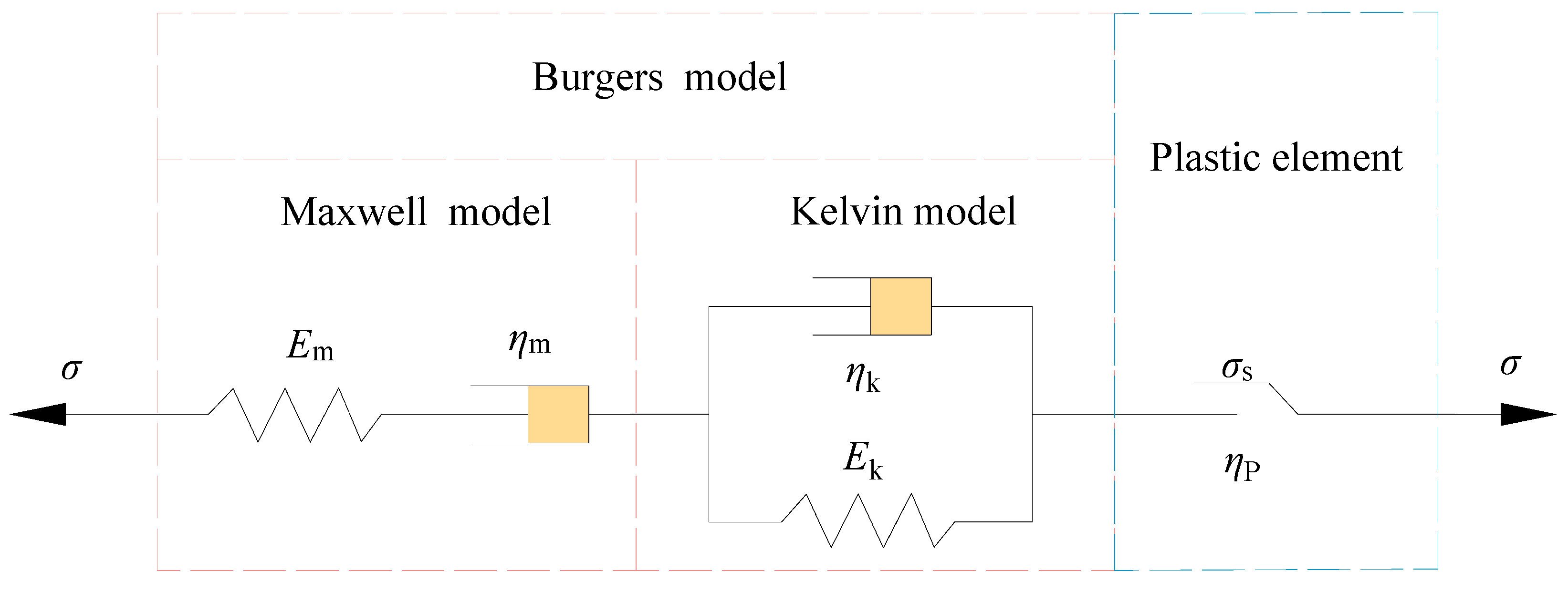
2.2. Construction of the CVISC Model

Due to the inherent characteristics of soft coal, such as its low strength, soft and brittle nature, and granular structure, it presents challenges in obtaining representative samples for testing. Therefore, the construction of a nonlinear discrete creep model specific to soft coal becomes necessary in order to understand its creep failure mechanism. To ensure the accuracy of the simulation, the parameters of the creep model are determined using the results obtained from uniaxial creep tests. In the selection of a creep model for soft coal, the classical Burgers model [40,41,42,43] is widely utilized due to its high accuracy in describing the steady-state deformation during coal rock creep. However, it has limitations in capturing the large nonlinear deformations observed in the accelerated creep stage. Based on the aforementioned analysis, it is evident that the deformation of soft coal roadways exhibits three distinct stages of creep. To simulate the creep failure of soft coal particles, the CVISC creep model [44] is employed, as it effectively characterizes the viscoelastic and plastic behaviors of soft coal. The model is illustrated in Figure 3.
When σ < σ s , the plastic element in the CVISC model is composed of the Maxwell model and the Kelvin model. The creep constitutive equation is expressed by Equation (1):
ε t = σ E m + σ η m t + σ E k 1 e E k η k t
In the formula, Em represents the elastic modulus of the Maxwell model, ηm represents the viscosity coefficient of the Maxwell model, Ek represents the Kelvin rheological coefficient, and ηk represents the viscosity coefficient of the Kelvin model.
When σ σ s ratio is considered, the Burgers model and the plastic element collaborate in the CVISC model. The total creep strain in the three-dimensional state can be represented as follows:
e · i j = e . i j k + e . i j m + e . i j p
In Equation (2), e . i j k and e . i j m represent the strain rates of the Kelvin and Maxwell components, respectively, while e . i j p represents the strain rate of the plastic element.
The strain rates of Kelvin and Maxwell are:
S i j = 2 N k e . i j k + 2 G k e i j k e ˙ i j m = S ˙ i j 2 G m + S i j 2 N m
For the strain rate of plastic elements, there are:
e . i j p = λ g σ i j 1 3 e . v o l p δ i j e . v o l p = λ g σ 11 + g σ 22 + g 33
where δ i j is the unit ball tensor symbol and e . v o l p is the volumetric strain rate. g is the potential function, which is used to determine whether the material is yielding or not. λ is a nonzero parameter that only applies during the process of plastic flow, and its value is determined by the specific plastic yield condition being applied.
In the Mohr-Coulomb criterion, for shear yielding, the specific expressions of the yield function f and its potential function g are as follows:
f = σ 1 σ 3 N ϕ + 2 C N ϕ g = σ 1 σ 3 N φ
For tensile yielding, the specific expressions of the yield function f and its potential function g are as follows:
f = σ t σ 3 g = σ 3
In the Equations (5) and (6), C represents the cohesion of the block, σ t represents the tensile strength of the block, σ 1 and σ 3 represent the maximum and minimum principal stresses, respectively. ϕ and φ represent the internal friction angle and dilatancy angle, respectively. The expressions for the yield function N ϕ and the potential function N φ are as follows:
N ϕ = 1 + sin ϕ / 1 sin ϕ N φ = 1 + sin φ / 1 sin φ
Considering the characteristics of soft coal, such as low strength, loose granularity, and strong flow properties, a Coulomb slip bondless contact model has been developed. This model does not incorporate normal and tangential tensile strength between blocks or particles, aiming to simulate the fracture and damage processes of inter-particle joints within the coal body. Within this model, the deformation characteristics of these joints are defined by the normal stiffness (kn) and tangential stiffness (ks), while the strength characteristics are defined by the friction angle (f). The mechanical attributes of the linear model are delineated by the normal and tangential stiffness values. The normal contact force is determined by the multiplication of the normal overlap and the normal stiffness, whereas the tangential contact force emerges from the cumulative shear force due to tangential relative displacement. This tangential contact force can, to some extent, reflect the particles’ loading history and path. When two blocks come into contact, the model adheres to the Coulomb slip criterion. The mechanical representation of this model is depicted in Figure 4a. In the UDEC software, the CVISC creep model is applied to the block element, while the Coulomb slip unbonded contact model is introduced into the joint to account for the strain rate in the accelerated creep stage. Utilizing the Trigon logic model, a nonlinear discrete creep model capable of describing the complete creep process of soft coal is established, as illustrated in Figure 4b.

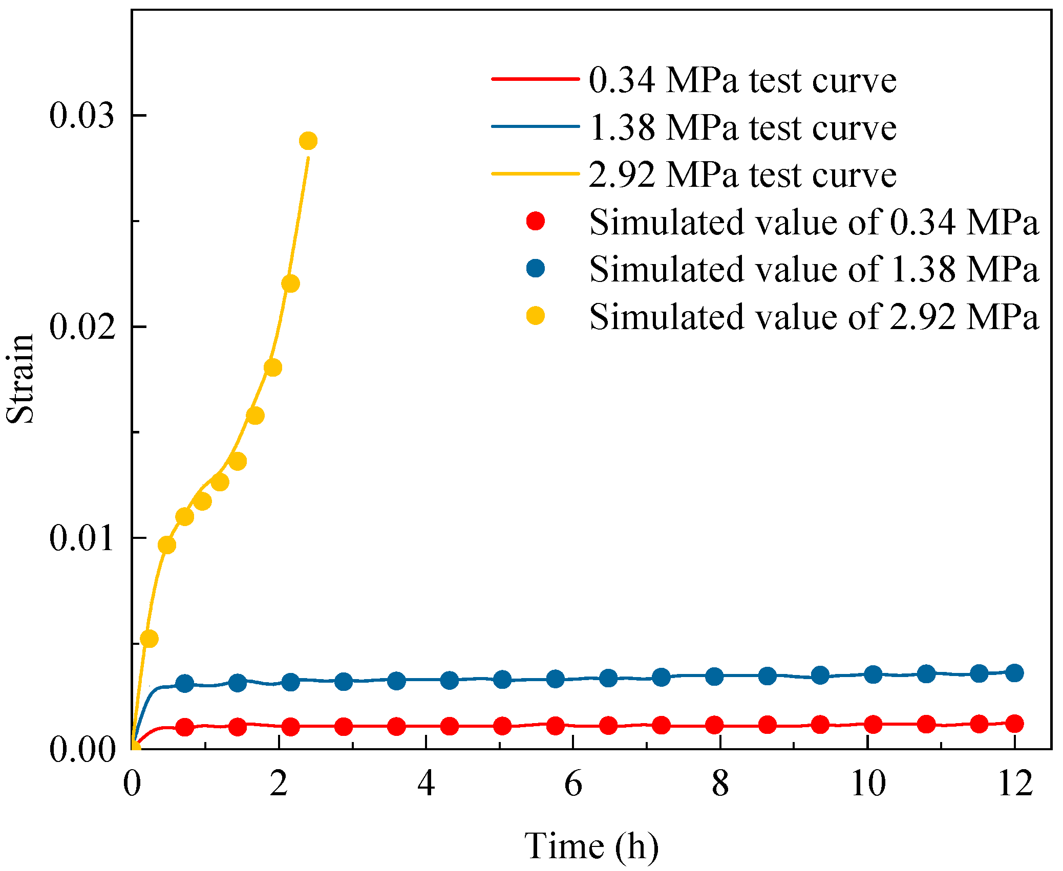
2.3. Model Parameter Identification and Verification

Before proceeding with model parameter identification, it is necessary to conduct uniaxial creep tests on the sampled return airway from the 11,000 working faces in the 11 mining areas of Quandian Coal Mine. Due to the low strength, softness, and fragility of the sampled coal seam, efforts were made to improve the testing process. Following the guidelines provided by the ISRM standard [45], a limited number of standard cylindrical specimens with dimensions of φ50 mm × 100 mm were manufactured and tested in the laboratory. The average uniaxial compressive strength of the three specimens was measured at 3.44 MPa, while the average yield strength was 2.92 MPa, approximately 85% of the ultimate failure strength of the specimens.
The CVISC creep model requires the determination of four parameters: Em, ηm, Ek, and ηk. To establish these parameters, the uniaxial creep experimental program from a previous study [46] was consulted. Uniaxial creep tests were performed on three specimens, designated as #1, #2, and #3, using the graded loading method. Stresses were incrementally applied at a rate of 5 N/s during the test, and each stress level was sustained for a duration of 12 h. This testing protocol was replicated for all three specimens. The ratio of each stress level to the peak strength was calculated under the ultimate destructive strength of the specimen, resulting in stress levels of 10%, 20%, 40%, 60%, and 80%. These five stress levels were established for analysis. In cases where the loading load failed to induce accelerated creep even after more than 12 h at the last stress level, the next level of loading was increased by 5% of the peak strength difference. This process was repeated until accelerated-state creep was observed in the specimen. Based on the uniaxial strength test results of the soft coal specimens, the initial deformation parameters and strength parameters of the blocks were determined. By comparing the initial values with the simulation results, the short-term deformation and mechanical parameters of the soft coal specimens were obtained through parameter adjustment, as presented in Table 1.
The nonlinear least squares method is used to identify the parameters of the loading data for each creep stage between the accelerated creep stages. The parameters of the block variables at all levels are obtained, and the joint model is modified based on the short-term parameters. Taking the example of the sample with a yield stress of 2.92 MPa entering the accelerated creep, the parameters of the modified joint model show minimal changes, and the initial values are still used. The calibration of the block parameters in the accelerated creep stage after correction is presented in Table 2.
The uniaxial creep test of soft coal was numerically simulated using the established particle discrete creep model as the calculation criterion. The actual experimental results were compared with the numerical simulation results, and a comparison diagram is presented in Figure 5 to verify the validity of the model. Illustrated in the figure are strain-time plots for soft coal specimens subjected to varying axial pressures in laboratory tests. The points of corresponding colors on the graph depict strain-time plots generated by the established creep model at different axial pressures. Despite some divergence between the numerical simulation results and the test results during the accelerated-state creep stage, the overall error falls within acceptable limits. Notably, during the decay-state creep stage and steady-state creep stage, the two trends exhibit close alignment, providing affirmation of the model’s rationality. Additionally, both the test and simulation curves exhibit the characteristic three-stage pattern of decay-state creep, steady-state creep, and accelerated-state creep. This resemblance to the actual creep behavior observed in field roadways further underscores the validation and logical soundness of the developed model.

3. Creep Instability Mechanism of the Soft Coal Roadway

3.1. Creep Characteristics of Soft Coal under Triaxial Compression

The numerical simulation of the creep test on soft coal specimens under triaxial compression was conducted using UDEC 7.0. The study focused on the deformation and fracture characteristics of microparticles and contacts in soft coal under confining pressure. Due to the exclusion of the specimen’s discrete nature in the numerical test, the triaxial loading process can be executed through gradual increments in stress levels using constant loading. The peripheral pressure is set at varying values of 0 MPa, 0.2 MPa, 0.4 MPa, and 0.6 MPa. In instances where the loading load reaches the last stress level and remains without accelerated creep for over 12 h, a 5% increase in peak strength relative to the level difference is applied for the subsequent round of constant level loading. This procedure is repeated until accelerated creep is observed in the specimen. For precise details of the experimental program, refer to Table 3.
By leveraging the FISH function inherent in the UDEC 7.0 software and extending its capabilities through secondary development, the accelerated creep rate curve of the specimen as it enters the accelerated creep stage under varying peripheral pressures was extracted. This extraction facilitates the analysis of the deformation characteristics exhibited by soft coal within the non-steady state creep condition across different peripheral pressures. Please refer to Figure 6 for a visual representation of these findings. The analysis results are as follows:
(1)
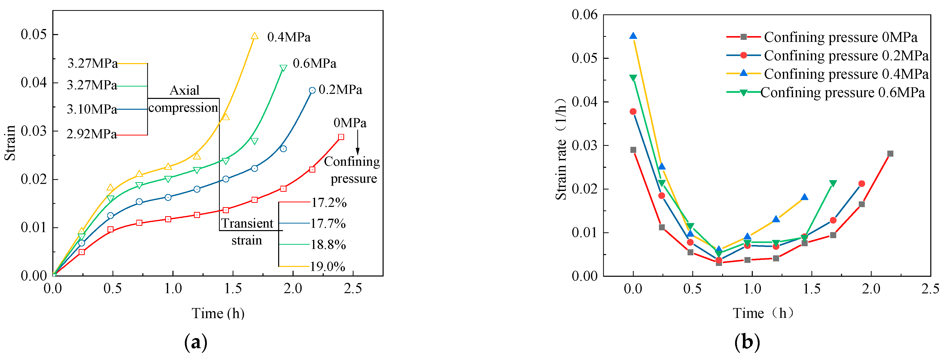
The creep deformation of soft coal exhibits a confining pressure effect within a certain range. Specifically, when the confining pressure is 0, 0.2 MPa, or 0.4 MPa, the initial strength of accelerated creep increases by 6.2% and 5.5%, respectively. This suggests that an increase in surrounding rock results in a higher stress level required for accelerated creep to occur. However, even when the confining pressure reaches 0.6 MPa, the specimen still undergoes accelerated creep under an axial pressure of 3.27 MPa. This indicates that as the axial pressure increases, the confining pressure effect on the creep process of soft coal gradually weakens.
(2)
Increasing the confining pressure can delay the onset of accelerated creep in soft coal. For instance, when the axial pressure is 3.27 MPa, the time of accelerated creep with a confining pressure of 0.4 MPa is delayed by 0.25 h compared to the case with a confining pressure of 0.6 MPa. From a deformation rate perspective, the overall deformation rate of the latter is lower than that of the former, resulting in a longer constant creep period. The start time of accelerated creep is also delayed. These observations suggest that under high confining pressure, the constant creep stage is longer, the accelerated creep is more moderate, and both the deformation amount and deformation rate are reduced.
(3)
Increasing the confining pressure has a restraining effect on the creep deformation of soft coal. As the confining pressure increases from 0 to 0.6 MPa, the proportion of instantaneous strain to total strain increases from 17.2% to 19.0%. However, the proportion of creep increment in each deformation stage following the instantaneous strain decreases from 82.8% to 81%. This indicates that higher confining pressure leads to a larger portion of instantaneous strain in the total deformation, while the contribution of creep deformation decreases slightly.
Figure 6. Accelerated creep curves of soft coal under different confining pressures: (a) Accelerated creep curve; (b) Creep rate.
Applsci 13 09344 g006

3.2. Creep Crack Propagation Characteristics of Soft Coal under Different Axial Pressures

In order to investigate the influence of confining pressure on the meso-fracture characteristics of soft coal specimens during the uniaxial unsteady creep process, the compiled FISH language was utilized to detect the number of micro-cracks that occur due to tensile and shear failures when the specimen reaches accelerated creep strength under different confining pressure conditions. The crack evolution state of each stage of uniaxial creep was illustrated on the surface of the specimen, as depicted in Figure 7a. It is evident that the number of shear cracks is significantly greater than the number of tensile cracks during the unsteady creep process of soft coal, encompassing the decay, steady, and accelerated creep stages. When considering the uniaxial strain curve, it becomes evident that during the occurrence of steady-state creep in the specimen, specifically in the deceleration and constant-speed creep stages, the increase in crack formation is primarily attributed to shear cracks. These shear cracks exhibit an X-shaped distribution, diagonally connected along both ends of the specimen. In the accelerated creep stage, there is a rapid increase in both shear and tensile cracks, with the growth rate showing an upward trend. Upon observing the surface of the specimen, it becomes apparent that some shear cracks have undergone a transformation into tensile cracks. Consequently, this transformation of shear cracks into tensile cracks contributes to the increased number of tensile cracks, serving as an indication of the unsteady creep behavior of soft coal.
Figure 7b displays the variation curves of tensile and shear cracks during the unsteady creep process under different confining pressures. It can be observed that, for the same duration of development time, the number of shear cracks in the specimen gradually increases with an increase in confining pressure, while the number of tensile cracks gradually decreases. This observation aligns with the creep failure pattern observed in specimens subjected to different confining pressures. Consequently, it can be concluded that an increase in confining pressure has the effect of reducing the number of tensile cracks in coal and consequently mitigating the unsteady creep deformation of soft coal.

3.3. Creep Instability Mechanism of the Roadway

According to the geological conditions of the transportation roadway in the 11,000 working faces of Quandian Coal Mine, a plane strain model was established using the discrete element software UDEC 7.0. The model had dimensions of 50 m × 50 m. The bottom boundary of the model was fixed, the left and right boundaries were deformation boundaries, and the top boundary was a stress boundary. A vertical stress of 10 MPa (equivalent to the self-weight stress of the overlying 400-m rock layer) was applied at the top of the model, and the lateral pressure coefficient was set to 1.5 based on the results of ground stress tests. It was determined that the rock mass within 10 m of the section represented the near area of the roadway. The FISH language was employed to monitor the fracture development process in the near area, and measurement points were arranged in the roof and floor of the roadway, as well as the midpoint of the two ribs, to monitor the surface deformation of the roadway. The numerical calculation model and the arrangement of measurement points can be seen in Figure 8.
For the sake of calculation accuracy, Voronoi Trigon polygonal joints are generated to represent the coal seam in the roadway. The block elements are modeled using the CVISC creep constitutive model. The roof and floor of the roadway were created using the JSET joint generator. The block failure criterion is based on the Mohr-Coulomb model, and the coal and rock joints follow the Mohr-Coulomb yield criterion. During the calculation process, the physical and mechanical parameters of the rock strata and joints are specified, as shown in Table 4. The rock mass parameters are obtained by applying the GSI rock mass classification method to the rock mechanics parameters obtained from laboratory mechanical tests. The physical and mechanical parameters, as well as the creep parameters used for the coal seam, are presented in Table 1 and Table 2, respectively.
In order to analyze the impact of creep on the deformation of a soft coal roadway, the deformation characteristics of the surrounding rock and the development of micro-cracks in the transportation roadway of the 11,000 working faces were simulated and analyzed under the original shed cable support mode. The UDEC software incorporates various predefined structural units, which encompass cable structural units for simulating anchor cables and liner structural units for replicating support methods such as roadway shelf support and anchor net support. The selection between these units hinges on the nature of the chosen support material. In the software, the utilization of these two support structures entails an initial model establishment followed by parameter assignment, enabling the support structure to fulfill its intended function. The original support model employs a 1 × 19 prestressing strand of Φ18.9 mm with a length of L8000 mm, boasting a breaking load of 607 kN for the anchor cable. In contrast, the shed support structure employs 36U steel. The precise parameters applied to these support structures in the experiment are detailed in Table 5 and Table 6.
Upon conducting simulations following the aforementioned steps and parameter settings, the displacement of the roadway over the course of excavation under the shed-cable support is graphically presented in Figure 9. From the results obtained, the following conclusions can be drawn:
(1)
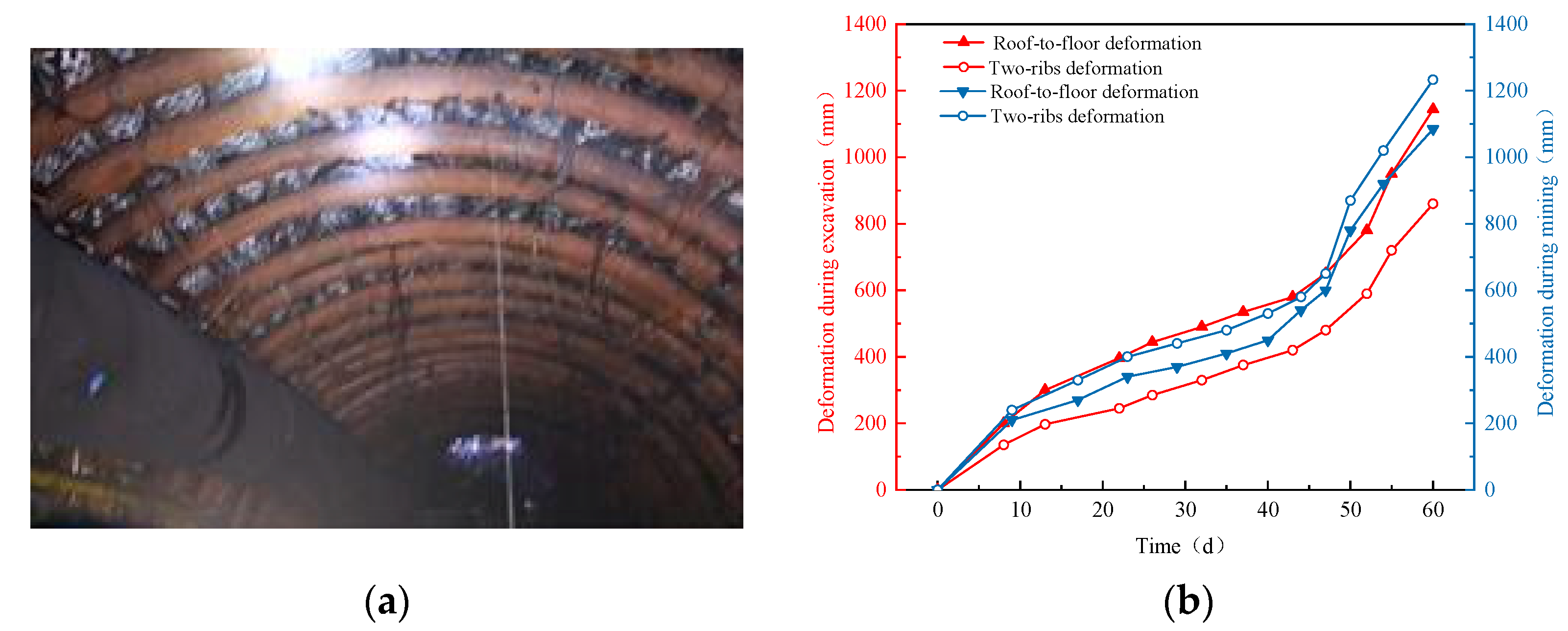
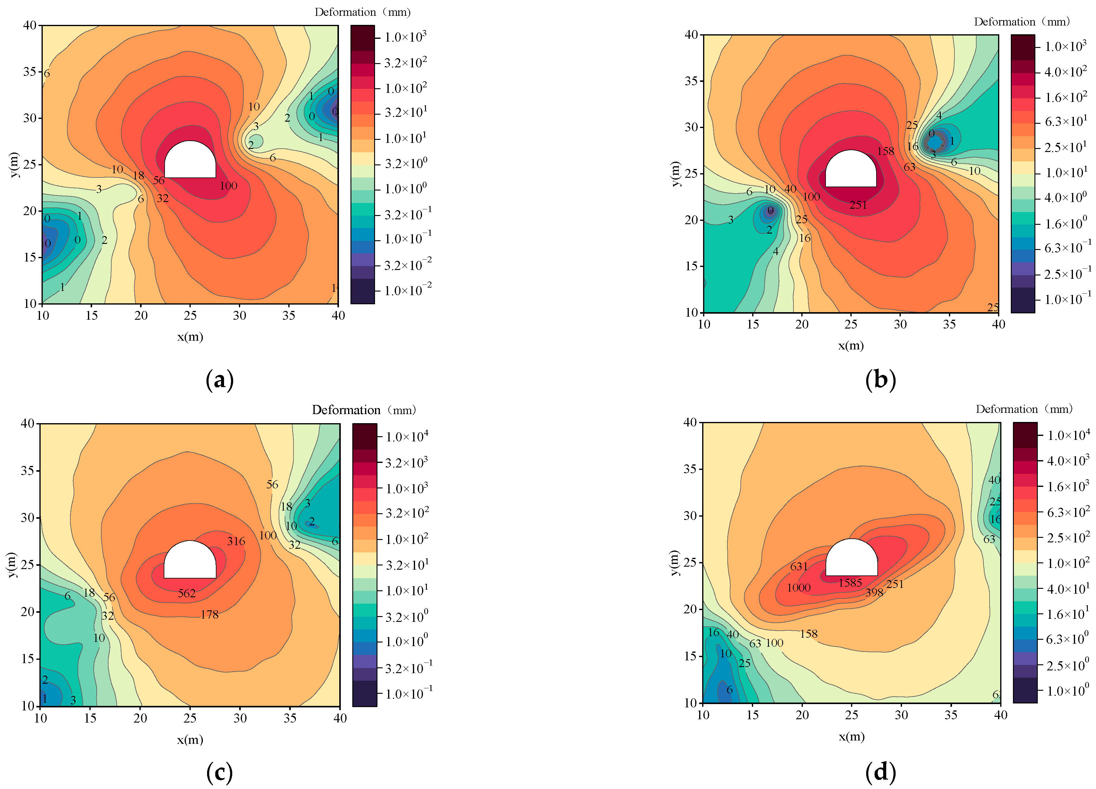
The deformation of the roadway exhibits significant asymmetric characteristics due to the dip angle of the strata. After implementing shed-cable support in the roadway, the first noticeable deformation occurs in the “triangular coal” region on the right side, specifically at the junction of the coal and rock on the right side. The subsequent deformation pattern is as follows: left side > floor > right side > roof. The maximum deformation is observed on the left side of the floor, with a heave of 2155 mm.
(2)
With the increase in support time under the shed cable support, the deformation of the two sides of the roadway and the roof and floor increases, and the increase rate gradually increases, showing an obvious accelerated creep phenomenon. Through comprehensive analysis, the floor and two sides of the coal body under the original shed-cable support method have obvious unsteady creep characteristics. The support strength of the shed-cable support method is low, and the long-term rheology of the surrounding rock cannot be continuously controlled. It will even aggravate the deformation of the floor coal body, and the surrounding rock control effect is poor.
Figure 9. Roadway deformation diagram under shed cable support: (a) 15 d, (b) 30 d, (c) 60 d, and (d) 120 d.
Applsci 13 09344 g009
As the support time increases under shed cable support, the deformation of both ribs of the roadway, as well as the roof and floor, increases. The rate of deformation increase also gradually rises, indicating the presence of accelerated creep. Comprehensive analysis reveals that the floor and ribs of the coal under the original shed-cable support method exhibit clear unsteady creep characteristics. The support strength provided by the shed-cable support method is insufficient to effectively control the long-term rheological behavior of the surrounding rock. In fact, it can even exacerbate the deformation of the floor coal and result in poor control over the surrounding rock.
The above research shows that the development of meso-cracks in the soft coal surrounding the rock can reflect the creep state of coal to a certain extent. Figure 10 shows a cloud diagram of the change in surrounding rock cracks with time under shed cable support. In Figure 10, the red lines represent the number of tensile cracks (represented by T), the green lines represent the number of shear cracks (represented by S), and the crack development area is represented by blue dotted lines. From Figure 10, the following observations can be made:
(1)
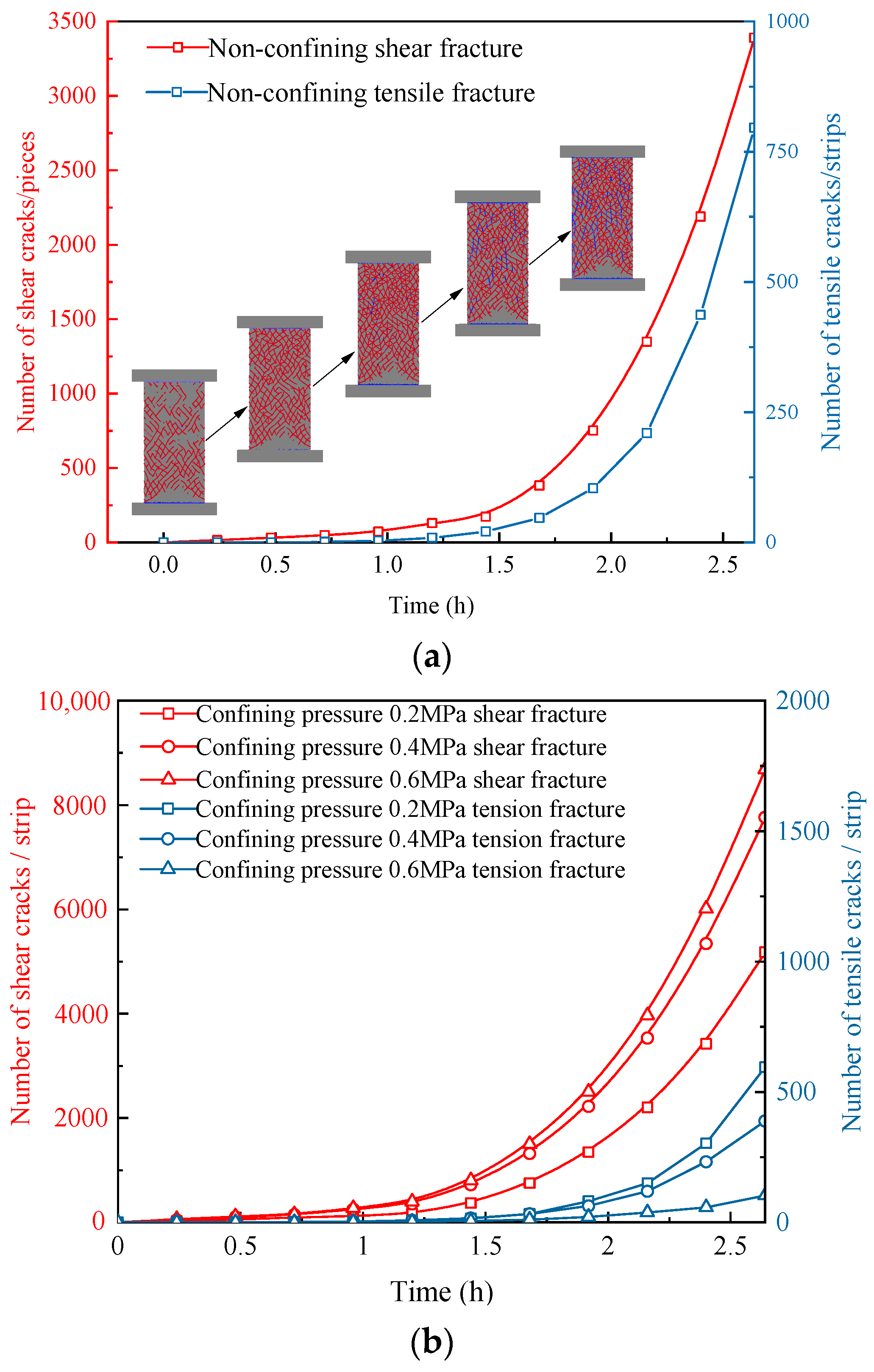
The development of fractures in the roadway is predominantly characterized by shear fractures. The number of shear cracks consistently exceeds the number of tensile cracks at each time period. Taking the example of a 15-day excavation, the monitoring area recorded 1714 shear cracks and 192 tensile cracks. As time progresses, the growth rate of shear cracks outpaces that of tensile cracks.
(2)
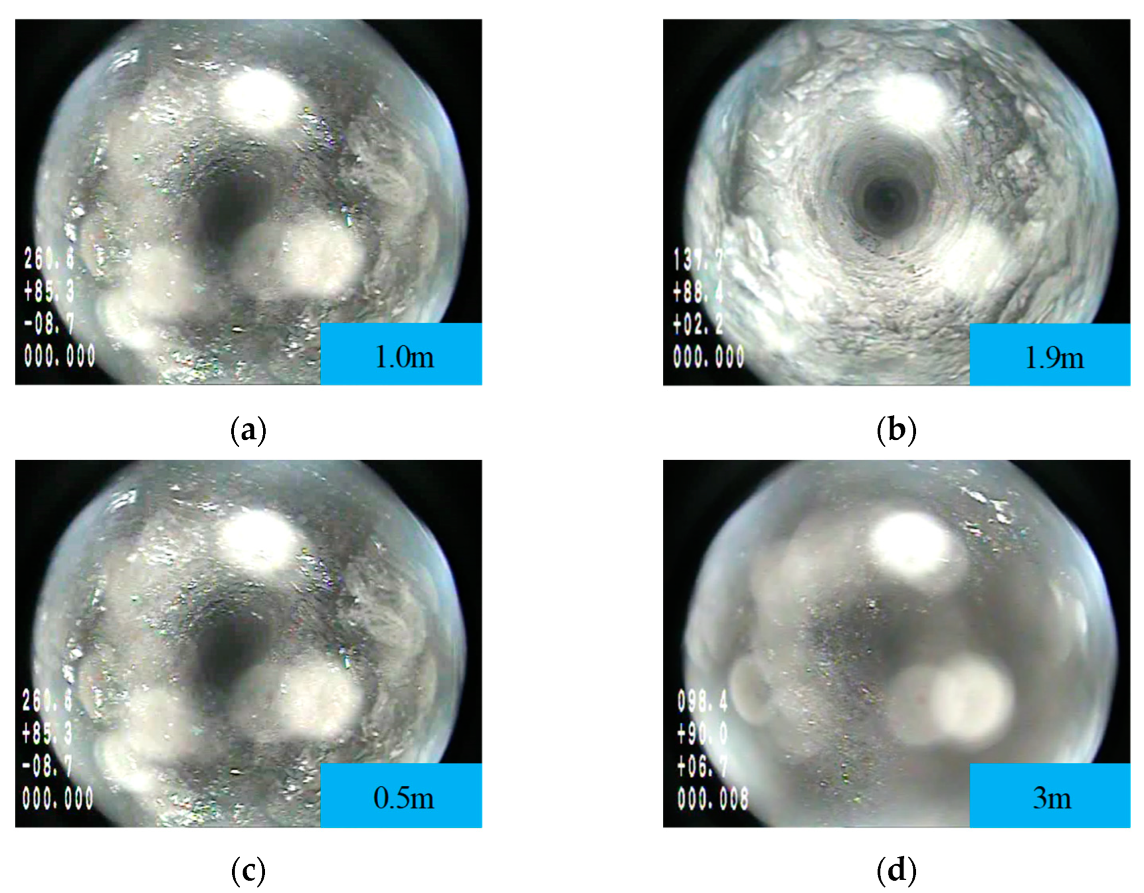
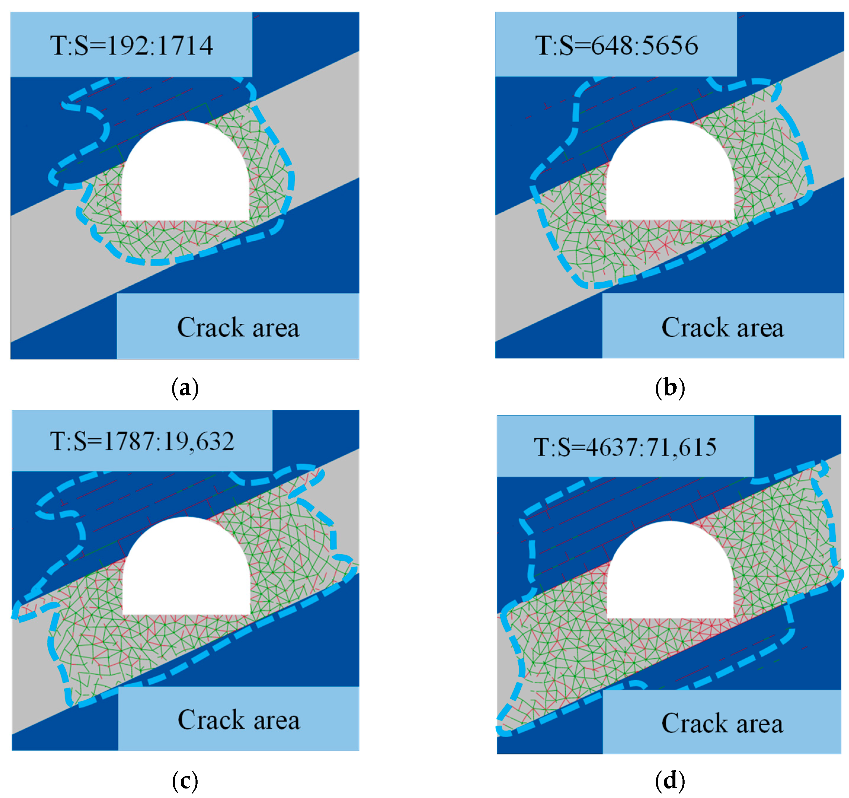
The distribution of cracks in the roadway varies with location. After a 15-day excavation, the shear cracks have developed to a depth of 1.3 m, primarily concentrated in the shallow portion of the surrounding rock. In contrast, the tensile cracks are mainly distributed on the surface of the roadway, with a development depth of approximately 0.6 m. As the excavation time progresses, the shallow shear cracks gradually transform into tensile cracks, forming a region of tensile crack distribution. The cracks further propagate into the deeper parts of the surrounding rock. After 120 days of excavation, the range of cracks caused by unsteady creep in the roadway exceeds 5.6 m.
(3)
The effectiveness of shed-cable support in inhibiting surrounding rock fractures diminishes over time. During the creep instability of the surrounding rock in the soft coal roadway, the distribution of cracks in the mudstone roof is minimal. However, the number of cracks in the coal body increases with time, and the growth rate accelerates. This indicates that the range of both steady and unsteady creeps in the coal body is expanding.
Figure 10. Fracture field diagram of surrounding rock under shed-cable support: (a) 15 d, (b) 30 d, (c) 60 d, and (d) 120 d.
Applsci 13 09344 g010
Based on the above analysis, the creep instability mechanism of the return airway in the 11,000 working faces can be summarized as follows:
(1)
In the early stages of roadway excavation, the shed cable support is unable to effectively inhibit the development of roadway cracks, leading to the rapid expansion of meso-cracks in the floor and ribs of the coal body. The deep coal body experiences steady-state creep dominated by shear cracks, while the surface of the coal body undergoes unsteady creep dominated by tensile cracks. With the increase in excavation time, the meso-cracks continue to propagate and expand into the deeper part of the surrounding rock, resulting in structural failure of the support system. As the shallow shear cracks in the surrounding rock gradually transform into tensile cracks, the number of tensile cracks increases, causing the coal body to transition from a steady-state creep state to an unsteady-state creep state.
(2)
During the development and expansion of cracks, the primary expansion of tensile cracks occurs from the coal seam and rock joints towards the deeper regions of the surrounding rock. This indicates that creep instability initially manifests at the junction between the two sides of the roadway and the floor coal. Hence, it can be inferred that the overall creep deformation of the roadway is caused by a combination of the creep deformation of the coal particles themselves and the propagation of meso-cracks between these particles when the two sides of the soft coal roadway and the floor coal are subjected to compression.
(3)
Following the excavation of the roadway, there is a change in the stress state of the surrounding rock surface and the shallow coal seam. The reduction in confining pressure leads to a decrease in the initial strength of accelerated creep in the coal, making it more susceptible to unsteady creep. Once the load on the coal reaches the threshold of the initial strength of accelerated creep, it transitions into an unsteady creep state, exhibiting the three-stage creep characteristics of decay-state creep, steady-state creep, and accelerated-state creep. As shear cracks transform into tensile cracks, the expansion of tensile cracks further amplifies the deformation rate of the coal experiencing unsteady creep. This, in turn, results in a rapid increase in deformation of the surrounding rock and ultimately leads to the overall onset of creep instability in the roadway.

4. The Proposal and Application of Primary Strong Active Support

4.1. The Proposal of Roadway Support Technology

According to the mechanism of roadway creep instability and considering the characteristics of weak and fractured roadways, extensive surrounding rock deformation, and failure of the supporting structure, this paper proposes a supporting principle. The principle combines high pre-tightening anchorage to increase the surface and internal confining pressure of the roadway, thereby improving the initial strength of accelerated creep in the coal body. Additionally, high-strength surface protection is utilized to enhance the initial stiffness of the support system, ensuring the integrity of the loose coal body within the roadway. Moreover, high-strength overall support and structural compensation are implemented in key local areas such as shoulder sockets and bottom angles.
Based on the above support principles, the primary strong active support technology of “high pre-tightening force of high-strength bolt and anchor cable, steel mesh + plastic mesh cooperative protection table” is proposed, and its support effect in creep control of surrounding rock of a soft coal roadway is simulated and verified in order to obtain the optimal support scheme parameters. To investigate the impact of bolt prestressing on the deformation of the surrounding rock, a study was conducted under the specified conditions: bolt length of 2.6 m and spacing of 0.8 m. The prestressing forces considered for the bolts are 20 kN, 40 kN, 60 kN, and 80 kN, respectively. The simulation was focused on the left rib, which experienced more significant damage. The precise location of this simulation is illustrated in Figure 8. The diamond metal mesh with Poisson’s ratio 0.3, elastic modulus 188 GPa, Φ4 mm, and the steel bar welding mesh with Poisson’s ratio 0.25, elastic modulus 210 GPa, and Φ4 mm, were selected to analyze the deformation of the left side of the roadway. The deformation of the left side of the roadway is shown in Figure 11.
Based on the aforementioned support principles, a primary strong active support technology is proposed, which involves the use of high pre-tightening forces applied to high-strength bolts and anchor cables, along with a cooperative protection surface consisting of steel mesh and plastic mesh. The effectiveness of this support technology in controlling creeps in the surrounding rock of soft coal roadways is simulated and verified to determine the optimal parameters for the support scheme. Different pre-tightening forces were employed to simulate the left side of the roadway, which exhibited more severe damage. The deformation of the left side of the roadway was analyzed using diamond metal mesh with a Poisson’s ratio of 0.3, an elastic modulus of 188 GPa, and a diameter of Φ4 mm, as well as steel bar welding mesh with a Poisson’s ratio of 0.25, an elastic modulus of 210 GPa, and a diameter of Φ4 mm. The deformation of the left side of the roadway is illustrated in Figure 11.
From Figure 11a, it is evident that the greater the pre-tightening force applied to the selected bolt, the more significant the reduction in deformation of the left side of the roadway. This indicates that increasing the confining pressure of the roadway can effectively mitigate the instability of creep deformation in the soft coal roadway. The creep characteristics of the roadway under different anchor mesh supports exhibit distinct patterns, as shown in Figure 11b. The deformation curves of the surrounding rock under the support of steel welded mesh and diamond metal mesh reflect the steady-state and unsteady-state creep characteristics of the left coal body, respectively. Specifically, the left side under the support of steel welded mesh enters the constant creep stage after 70 days of deceleration creep, whereas the diamond metal mesh experiences accelerated creep after 90 days of roadway excavation. These observations indicate that the steel welded mesh, with its higher stiffness and larger support parameters, is beneficial in controlling the overall deformation of the roadway and suppressing the occurrence of accelerated creep.
According to the aforementioned research, the appropriate parameters were selected based on the parameter selection principle of high pre-tightening force and high stiffness protection surface construction. These parameters were used to simulate the control effect of the primary strong active support technology on the creep effect of a soft coal roadway using UDEC software. The parameters involved in the technical scheme include a bolt length of 2600 mm, a pre-tightening force of 60 kN, a spacing of 800 mm, an anchor cable length of 3500 mm/8000 mm, a pre-tightening force of 120 kN, a spacing of 1600 mm, and the selection of Q235 steel mesh for the anchor net with an elastic modulus of 210 GPa, a Poisson’s ratio of 0.25, and a diameter of 4mm. For the remaining parameters used in the simulation, please consult Table 6. Figure 12 depicts the deformation characteristics of the surrounding rock of the roadway under the condition of strong primary active support. Figure 13, on the other hand, presents the cloud diagram of the surrounding rock fracture field over time under the primary strong active support.
From the deformation characteristics of the roadway surrounding rock under primary strong support and the cloud diagram depicting the changing crack field over time, the following observations can be made:
(1)
The distribution range and density of cracks in the surrounding rock decrease under strong primary active support. For example, after 120 days of roadway excavation, there are fewer tensile cracks on the right side of the roadway compared to the left side. The development range of shear cracks on both sides is approximately 2.4 m, which is 57.1% lower than the original support. The number of tensile and shear cracks in the surrounding rock is 399 and 30,494, respectively, representing a reduction of 91.4% and 57% compared to the shed cable support.
(2)
The rate of fracture development decreases with strong primary active support. This is because strong primary active support increases the confining pressure strength of the roadway and improves the yield strength of the roadway, thereby reducing the occurrence of accelerated creep. The strong primary active support effectively controls the creep of the roadway during the steady-state creep stage. Compared to the roadway supported by shed cables during the same period, the overall rate of fracture development is reduced.
(3)
The deformation of the surrounding rock decreases under strong primary active support. The overall deformation of the roadway becomes more balanced, and the deformation rate gradually decreases. During the simulated 120 days of roadway excavation, the maximum deformation of 250 mm occurs at the floor position. This is significantly lower compared to the maximum floor heave of 2155 mm under shed cable support. The control effect on the roadway is highly significant, and the deformation in other parts of the roadway under primary strong active support is also lower compared to the original support.
In summary, strong primary active support proves to be effective in inhibiting the development and expansion of cracks in the surrounding rock of soft coal roadways, particularly in suppressing the growth of tensile cracks. Additionally, it reduces the steady-state creep rate of the soft coal surrounding rock, enhances the initial creep strength of the surrounding rock, and mitigates the occurrence of unsteady creep and subsequent creep instability in the roadway.

4.2. Engineering Practice

Based on the above analysis, the new support method for the return airway in the 11,000 working faces involves implementing the anchor net cable combined support. The support scheme includes using Φ22 mm, L2600 mm left-handed non-longitudinal rebar threaded steel anchor rods with a spacing of 800 × 800 mm and a pre-tightening torque of not less than 450 N·m, along with Φ12 mm steel ladder beams. The anchor cables are Φ21.6 mm, L8000 mm (ribs are 4000 mm), 1 × 19 steel strands, with a row spacing of 1600 mm × 1600 mm and a pre-tightening force of not less than 200 kN. BHW-280-3.0 W steel belts are used in conjunction with plastic mesh and Q235 steel mesh for surface protection. The support scheme is illustrated in Figure 14a. The designed support scheme was implemented through field construction. The surface deformation of the roadway was monitored using the cross-point method for a period of 100 days, and the force of the anchor cable was recorded using the MCS-400 self-recording hydraulic pillow. Three stations, labeled WY-I, WY-II, and WY-III, were set up with a distance of 10 m between each station. These stations were positioned in the area of anchor cable support, located between 100 m and 120 m from the opening of the roadway, as depicted in Figure 14b.
During tunneling and mining, the deformation curve of the roadway surface is shown in Figure 15. In Figure 15a, the deformation of the right side, left side, roof, and floor of the roadway under the new support mode did not enter the accelerated creep stage with a large deformation rate. With the increased excavation time of the section, the overall deformation of the roadway tends to be stable. After 60 days of excavation, the deformation of the roadway surface is greatly reduced, which is consistent with the steady-state creep characteristics. The deformation of each part of the section from large to small is the bottom plate > left side > right side > roof. The maximum deformation of the roof and floor of the roadway is 246 mm, and the maximum deformation of the two sides is 204 mm.
In Figure 15b, the deformation of each part of the section from large to small is floor > left side > right side > roof. The maximum roof subsidence and floor heave of the roadway are 88 mm and 370 mm, respectively, and the average deformation rate of the floor is 4.3 times that of the roof. The maximum deformation of the left side is 224 mm, and the maximum deformation of the right side is 156 mm. The average deformation rate of the left side is 1.4 times that of the right side. The maximum deformation of the roof and floor of the roadway is 170 mm, and the maximum deformation of the two sides is 172 mm.
During tunneling and mining, the deformation curve of the roadway surface is illustrated in Figure 15. In Figure 15a, the deformation of the right rib, left rib, roof, and floor of the roadway under the new support mode did not enter the accelerated creep stage with a large deformation rate. As the excavation time for the section increased, the overall deformation of the roadway tended to stabilize. After 60 days of excavation, the deformation of the roadway surface significantly decreased, indicating steady-state creep characteristics. The ranking of deformation for each section part, from large to small, is floor > left rib > right rib > roof. The maximum deformation of the roof and floor of the roadway is 246 mm, and the maximum deformation of the two ribs is 204 mm.
In Figure 15b, the ranking of deformation for each section part, from large to small, is floor > left rib > right rib > roof. The maximum roof subsidence and floor heave of the roadway are 88 mm and 370 mm, respectively, with the average deformation rate of the floor being 4.3 times that of the roof. The maximum deformation of the left rib is 224 mm, and the maximum deformation of the right rib is 156 mm. The average deformation rate of the left rib is 1.4 times that of the right rib. The maximum deformation of the roof and floor of the roadway is 170 mm, and the maximum deformation of the two ribs is 172 mm.
During the excavation and subsequent mining phases, the variation in anchor cable force within the roadway is illustrated in Figure 16. In Figure 16a, the pre-tensioning force applied to the anchor cable falls within the range of 170 kN to 182 kN. This configuration yields a distinctive pattern of nonlinear growth, followed by a tendency toward stabilization. Notably, due to the anchor cable’s installation at a distance of 60 m from the headland, both the right rib and roof anchor cable forces eventually achieve a state of equilibrium. Specifically, the right rib anchor cable stabilizes at 186 kN, while the roof anchor cable reaches a steady 210 kN. At a distance of 100 m from the headland, the left rib anchor cable also stabilizes at 210 kN. In Figure 16b, the distribution of forces across the anchor cables is displayed. Remarkably, the roof anchor cable bears the greatest force, peaking at 298 kN, which corresponds to 49% of its breaking load. Subsequently, the left rib anchor cable follows with 271 kN (45%), while the right rib anchor cable also hits a force of 298 kN (45%). Furthermore, the right rib anchor cable experiences a stress level of 231.7 kN, equivalent to 38% of its breaking load. These findings collectively indicate that the anchor cable’s role intensifies during the mining phase, yet its operational resistance remains below its breaking load.
Based on the observation results during tunneling and mining, the maximum deformation of the two ribs of the surrounding rock, as well as the roof and floor, during the tunneling period is 246 mm and 204 mm, respectively. These values are 76.4% and 71.9% lower than those observed with shed cable support. During the mining period, the maximum deformations are 450 mm and 380 mm, respectively, which meet the production requirements. The control effect is depicted in Figure 17. The instability deformation of the roadway surrounding rock is effectively controlled during excavation and mining, thus verifying the effectiveness of the primary strong active support technology in soft coal roadway support.

5. Conclusions

(1)
According to the three-stage creep characteristics observed in the deformation of the 11,050 roadways, the CVISC model, which is capable of describing such characteristics, was chosen. Considering the small size, granular nature, and low strength of soft coal, the Coulomb slip unbonded contact joint model was selected. A creep model for soft coal is constructed in UDEC software, and the creep parameters are determined using the least squares method. The triaxial creep characteristics of soft coal are then studied. The results indicate that higher confining pressures lead to lower amounts of creep and lower creep rates in coal. This implies that the initial strength of accelerated creep in coal increases under higher confining pressures.
(2)
The uniaxial creep crack propagation law of soft coal specimens was determined using the FISH language. During the decay and steady creep stages, the number of cracks increased gradually, with shear cracks being predominant. An important characteristic of soft coal specimens entering the accelerated creep stage is the rapid increase in tensile cracks. Increasing the confining pressure is beneficial for reducing the number and growth rate of tensile cracks in coal, thus avoiding the occurrence of unsteady creep.
(3)
The creep deformation of coal particles in the surrounding rock of a soft coal roadway, along with the development of meso-cracks between particles and changes in stress state after roadway excavation, contribute to the overall creep failure of the roadway. The low confining pressure provided by the shed cable support results in a continuous increase in the number of cracks in the coal body over time. Furthermore, the inhibitory effect of the support on surrounding rock cracks weakens over time, revealing the underlying mechanism of creep instability in the return air roadway of the 11,000 working faces.
(4)
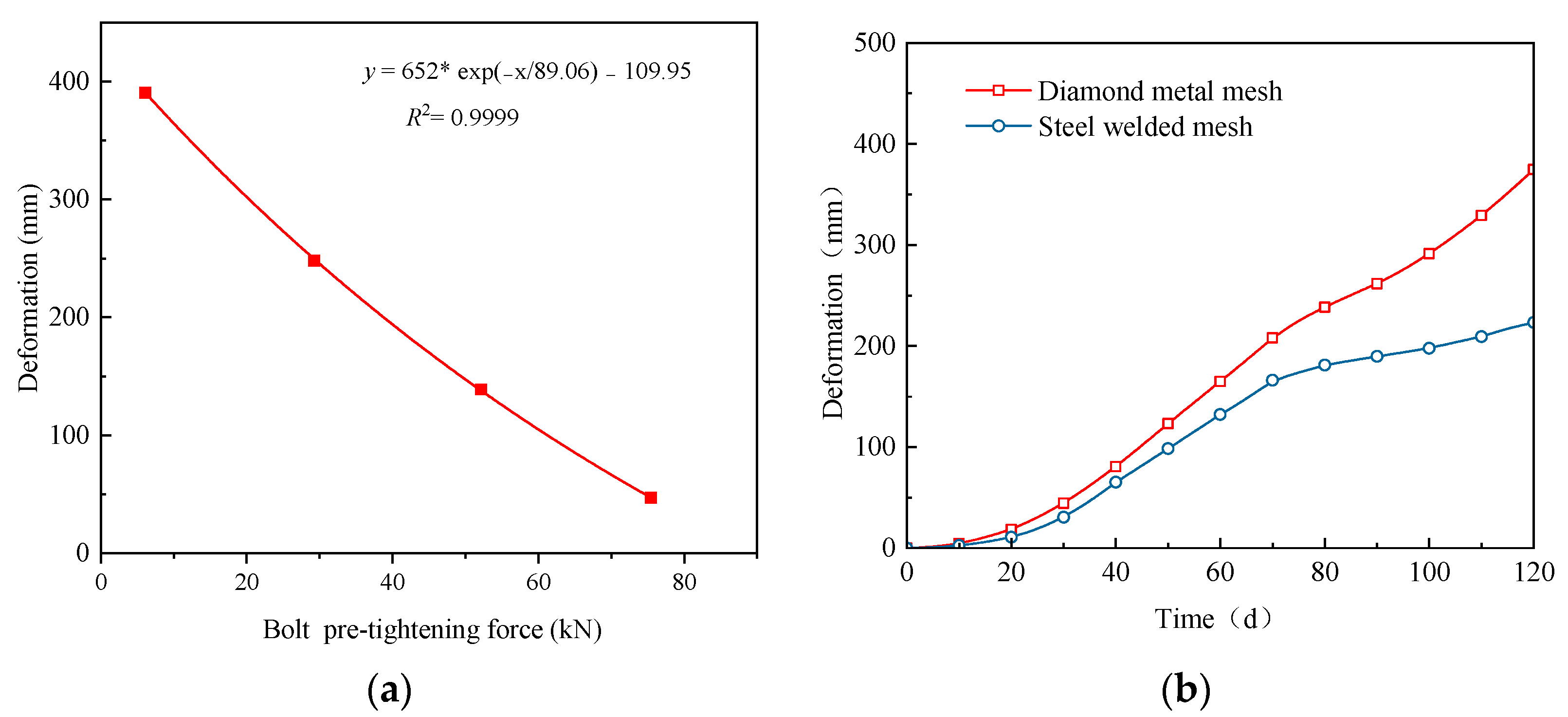
According to the characteristics of creep instability in soft coal roadways, a corresponding support principle is proposed. The principle suggests employing high pre-tightening force anchor cable support to enhance the surface and internal confining pressure of the roadway, increase the initial strength of accelerated creep in coal, improve the integrity of the soft coal roadway, enhance the strength of the near-surface surrounding rock, and control the surface deformation of the roadway. Considering the asymmetric deformation of the surrounding rock in the roadway, it is essential to address “structural compensation” in specific key areas such as the shoulder socket and bottom angle. This involves dealing with the deformation asymmetry in these areas and inhibiting the development and expansion of tensile and shear cracks at the junction of the roadway floor and the two sides of the coal rock.
(5)
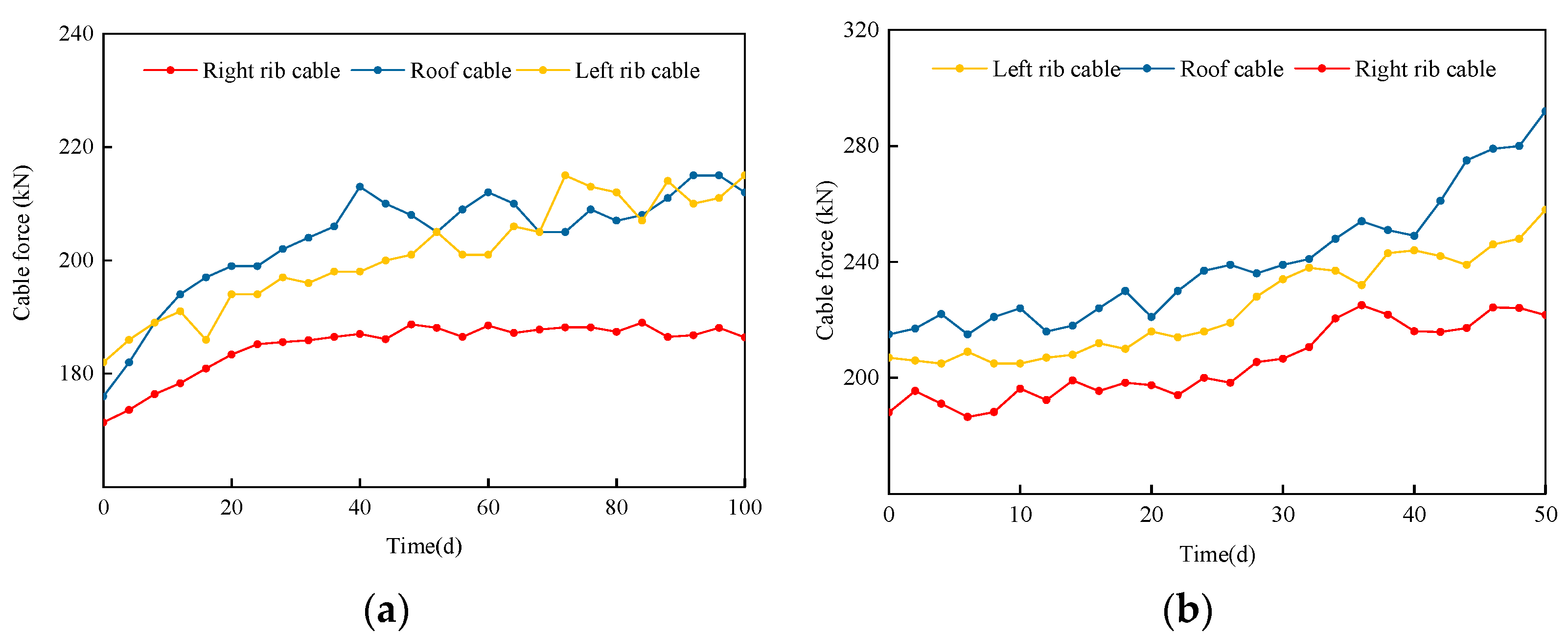
The primary strong active support technology, comprising high pre-tightening force high-strength bolts and anchor cables, along with a cooperative protection surface using steel mesh and plastic mesh, is proposed for the return airway of the 11,000 working faces. The selection principle of support parameters is clearly defined, and an industrial test is conducted to evaluate its effectiveness. The results demonstrate a remarkable control effect on the roadway, confirming the success of this proposed support technology.

Author Contributions

Conceptualization, F.W.; Methodology, F.W., H.L. and X.Y.; Software, J.Z., P.Y., H.L. and X.Y.; Validation, F.W., H.G., C.L., P.Y. and H.L.; Formal analysis, F.W., J.Z., P.Y. and H.L.; Investigation, C.L. and Y.L.; Resources, C.L.; Writing—original draft, H.G. and J.Z.; Writing—review & editing, H.G.; Visualization, X.C., M.W., Y.J., Y.C. and S.L.; Supervision, X.C., M.W., Y.J., P.W., H.Z. and Z.G.; Project administration, X.C., M.W., Y.J. and P.W. All authors have read and agreed to the published version of the manuscript.

Funding

The work was supported by the National Natural Science Foundation of China (No. 52174138). The authors gratefully acknowledge the financial support of the agencies mentioned above.

Institutional Review Board Statement

Not applicable.

Informed Consent Statement

Not applicable.

Data Availability Statement

The data that support the findings of this study are available on request from the corresponding author upon reasonable request.

Conflicts of Interest

The authors declare no conflict of interest.

References

  1. He, M.C. Progress and challenges of soft rock engineering in depth. J. China Coal Soc. 2014, 39, 1409–1417. [Google Scholar]
  2. Li, G.C.; Yang, S.; Sun, Y.T.; Xu, J.H.; Li, J.H. Research progress of roadway surrounding strata rock control technologies under complex conditions. Coal Sci. Technol. 2022, 50, 29–45. [Google Scholar]
  3. Li, G.; Ma, F.S.; Guo, J.; Zhao, H.; Liu, G. Study on deformation failure mechanism and support technology of deep soft rock roadway. Eng. Geol. 2020, 264, 105262. [Google Scholar] [CrossRef]
  4. Sun, L.H.; Sun, H.Y.; Zhang, X.J.; Mu, Y.P.; Wang, K.; Yang, X.D.; Yang, B.S.; Lan, C.R. Large deformation characteristics and full cable support technology of dynamic pressure roadways in extremely soft coal seams. J. Min. Saf. Eng. 2021, 38, 937–945. [Google Scholar]
  5. Zhao, B.Y.; Liu, D.Y.; Zheng, Y.R.; Liu, H. Uniaxial compressive creep test of red sandstone and its constitutive model. J. Min. Saf. Eng. 2013, 30, 744–747. [Google Scholar]
  6. Wu, L.Z.; Luo, X.H.; Li, S.H. A new model of shear creep and its experimental verification. Mech. Time-Depend. Mat. 2021, 25, 429–446. [Google Scholar]
  7. Shu, Z.L.; Liu, B.X.; Huang, S.; Wei, Y.H.; Zhao, B.Y. Nonlinear viscoelasto-plastic creep model of soft rock and its parameters identification. J. Min. Saf. Eng. 2017, 34, 803–809. [Google Scholar]
  8. Feng, W.; Qiao, C.; Niu, S.; Yang, Z.; Wang, T. An improved nonlinear damage model of rocks considering initial damage and damage evolution. Int. J. Damage Mech. 2020, 29, 1117–1137. [Google Scholar] [CrossRef]
  9. Zhang, Z.L.; Xu, W.Y.; Wang, R.B.; Zhang, Y. Study of nonlinear viscoel asto-plastic rheological model of sandstone with weak plane. Chin. J. Rock Mech. Eng. 2011, 30, 2634–2639. [Google Scholar]
  10. Cheng, H.; Zhang, Y.; Zhou, X. Nonlinear creep model for rocks considering damage evolution based on the modified Nishihara model. Int. J. Geomech. 2021, 21, 04021137. [Google Scholar] [CrossRef]
  11. Yang, W.; Zhang, Q.; Li, S.; Wang, S. Time-Dependent Behavior of Diabase and a Nonlinear Creep Model. Rock Mech. Rock Eng. 2014, 47, 1211–1224. [Google Scholar] [CrossRef]
  12. Fan, Y.Q.; Yang, K.Q.; Wang, W.M. Study of creep mechanism of argillaceous soft rocks. Chin. J. Rock Mech. Eng. 2010, 29, 1555–1561. [Google Scholar]
  13. Qiao, L.; Wang, Z.; Liu, J.; Li, W. Internal state variable creep constitutive model for the rock creep behavior. Bull. Eng. Geol. Environ. 2022, 81, 456. [Google Scholar] [CrossRef]
  14. Jiang, H.Y.; Liu, D.Y.; Zhao, B.Y.; Li, D.S. Nonlinear creep constitutive model of rock under high confining pressure and high water pressure. J. Min. Saf. Eng. 2014, 31, 284–291. [Google Scholar]
  15. Yan, B.; Guo, Q.; Ren, F.; Cai, M. Modified Nishihara model and experimental verification of deep rock mass under the water-rock interaction. Int. J. Rock. Mech. Min. 2020, 128, 104250. [Google Scholar] [CrossRef]
  16. Ding, P.; Xu, R.; Hu, Y.; Xie, J.; Ju, L. Experimental investigation and constitutive modeling of the shear creep behavior of an overconsolidated soft clay. Bull. Eng. Geol. Environ. 2020, 79, 3063–3073. [Google Scholar] [CrossRef]
  17. Liu, W.B.; Zhang, S.G.; Chen, L. Time-dependent creep model of rock based on unsteady fractional order. J. Min. Saf. Eng. 2021, 38, 388–395. [Google Scholar]
  18. Chen, X.; Wang, X.; Zhang, D.; Qin, D.; Wang, Y.; Wang, J.; Chang, Z. Creep and Control of the Deep Soft Rock Roadway (DSRR): Insights from Laboratory Testing and Practice in Pingdingshan Mining Area. Rock Mech. Rock Eng. 2022, 55, 363–378. [Google Scholar]
  19. Zhou, C.; Yu, L.; You, F.; Liu, Z.; Liang, Y.; Zhang, L. Coupled seepage and stress model and experiment verification for creep behavior of soft rock. Int. J. Geomech. 2020, 20, 04020146. [Google Scholar] [CrossRef]
  20. Wu, C.; Guo, Q.W.; Hong, T.; Chen, Y.J. Uniaxial rheological damage experiment of soft rock based on the ultrasonic testing. J. Coal Geol. Explor. 2017, 45, 105–111, 120. [Google Scholar]
  21. Huang, T.; Li, J.; Zhao, B. Nonlinear creep damage model of rock salt considering temperature effect and its implement in FLAC 3D. Geomech. Eng. 2021, 26, 581–591. [Google Scholar]
  22. Ran, H.; Guo, Y.; Feng, G.; Qi, T.; Du, X. Creep properties and resistivity-ultrasonic-AE responses of cemented gangue backfill column under high-stress area. Int. J. Min. Sci. Technol. 2021, 3, 401–412. [Google Scholar] [CrossRef]
  23. Huang, P.; Zhang, J.X.; Spearing, A.J.S.; Chai, J.; Dong, C.W. Experimental study of the creep properties of coal considering initial damage. Int. J. Rock Mech. Min. Sci. 2021, 139, 104629. [Google Scholar] [CrossRef]
  24. Zhang, H.M.; Wang, F.Y.; Li, H.R.; Yang, G.S.; Shen, Y.J.; Liu, H.; Lu, Y.N. Study on creep damage model of coal-rock under different infiltration time and stress level. J. Min. Saf. Eng. 2023, 40, 399–407. [Google Scholar]
  25. Cheng, A.P.; Fu, Z.X.; Liu, L.S.; Dai, S.Y.; Huang, S.B.; Ye, Z.Y. Creep hardening-damage characteristics and nonlinear constitutive model of cemented backfill. J. Min. Saf. Eng. 2022, 39, 449–457. [Google Scholar]
  26. Shan, R.L.; Bai, Y.; Ju, Y.; Han, T.Y.; Dou, H.Y.; Li, Z.L. Study on the Triaxial Unloading Creep Mechanical Properties and Damage Constitutive Model of Red Sandstone Containing a Single Ice-Filled Flaw. Rock Mech. Rock Eng. 2021, 54, 833–855. [Google Scholar] [CrossRef]
  27. He, M.C.; Wang, X.Y.; Liu, W.T.; Yang, S.B. Numerical simulation on asymmetric deformation of deep soft rock roadway in kongzhuang coal mine. J. Rock Mech. Eng. 2008, 197, 673–678. [Google Scholar]
  28. He, M.C.; Yuan, Y.; Wang, Y.; Wang, X.L.; Wu, Z.Q.; Liu, C.; Jiang, Y.L. Control technology for large deformation of mesozoic compound soft rock in xinjiang and its application. J. Rock Mech. Eng. 2013, 32, 433–441. [Google Scholar]
  29. Wu, F.F.; Zhang, J.; Wang, P.; Zhao, X.P.; Xuan, Y.W.; Lv, B.; Wei, J.K.; Gao, Z.Q.; Liu, S.B.; Gu, H.Y. Application and Principle of Bolt-Mesh-Cable Control Technology in Extremely Soft Coal Seam Roadway. Geofluids 2023, 2023, 9444486. [Google Scholar] [CrossRef]
  30. Yang, W.D.; Wang, X.P.; Ivanović, A.; Zhang, X. Coupled analytical solutions for circular tunnels considering rock creep effects and time-dependent anchoring forces in prestressed bolts. Tunn. Undergr. Space Technol. 2023, 134, 104954. [Google Scholar] [CrossRef]
  31. Zhu, Q.W.; Li, T.C.; Zhang, H.; Ran, J.L.; Li, H.; Du, Y.T.; Li, W.T. True 3D geomechanical model test for research on rheological deformation and failure characteristics of deep soft rock roadways. Tunn. Undergr. Space Technol. 2022, 128, 104653. [Google Scholar] [CrossRef]
  32. Zhan, Q.J.; Shahani, N.M.; Zheng, X.G.; Xue, Z.C.; He, Y.Y. Instability mechanism and coupling support technology of full section strong convergence roadway with a depth of 1350 m. Eng. Fail. Anal. 2022, 139, 106374. [Google Scholar] [CrossRef]
  33. Zhu, Q.W.; Li, T.C.; Ran, J.L.; Du, Y.T.; Zhang, H.; Jiang, H. Model test on creep deformation and failure characteristics of soft rock roadways. Eng. Fail. Anal. 2022, 141, 106670. [Google Scholar] [CrossRef]
  34. Li, G.C.; Sun, C.L.; Sun, Y.T.; Cui, G.J.; Qian, D.Y. Macroscopic and microcosmic consolidation law of loose coal grouting based on the “two media-three interfaces” model. J. China Coal Soc. 2019, 44, 427–434. [Google Scholar]
  35. Wang, X.F.; Chen, X.Y.; Wang, J.Y.; Chang, Z.C.; Qin, D.D.; Huang, Q.X. Study on creep failure mechanism and control of the deep soft rock roadway in pingdingshan mining area. J. Min. Saf. Eng. 2022, 1–12. [Google Scholar] [CrossRef]
  36. Wang, M.; Zheng, D.J.; Wang, X.Y.; Xiao, T.Q.; Shen, W.L.; Song, Z.F. Deformation characteristics and creeping control of deep roadway with pressure-relief borehole. J. Min. Saf. Eng. 2019, 36, 437–445. [Google Scholar]
  37. Fan, L.; Wang, W.; Yuan, C.; Peng, W. Research on large deformation mechanism of deep roadway with dynamic pressure. Energy Sci. Eng. 2020, 8, 3348–3364. [Google Scholar] [CrossRef]
  38. Huang, W.P.; Li, C.; Xing, W.B.; Yuan, Q.; Qu, W.L. Asymmetric deformation mechanism and control technology of roadway with depth over 1000 meters under rheological state. J. Min. Saf. Eng. 2018, 35, 481–488+495. [Google Scholar]
  39. Jing, W.; Liu, S.X.; Yang, R.S.; Jing, L.W.; Xue, W.P. Mechanism of aging deformation zoning of surrounding rock in deep high stress soft rock roadway based on rock creep characteristics. J. Appl. Geophys. 2022, 202, 104632. [Google Scholar] [CrossRef]
  40. Yin, Z.C.; Zhang, X.; Li, X.H.; Zhang, J.Q.; Zhang, Q.S. Modified Burgers model of creep behavior of grouting-reinforced body and its long-term effect on tunnel operation. Tunn. Undergr. Space Technol. 2022, 127, 104537. [Google Scholar] [CrossRef]
  41. Okuka, A.S.; Zorica, D. Fractional Burgers models in creep and stress relaxation tests. Appl. Math. Model. 2020, 77, 1894–1935. [Google Scholar] [CrossRef]
  42. Tang, J.; Peng, Z.B.; He, Z.M. Research on improved Burgers model based on rock mass creep test. J. Cent. South Univ. (Sci. Technol.) 2017, 48, 2414–2424. [Google Scholar]
  43. Lin, H.; Zhang, X.; Cao, R.; Wen, Z. Improved nonlinear Burgers shear creep model based on the time-dependent shear strength for rock. Environ. Earth Sci. 2020, 79, 1–9. [Google Scholar] [CrossRef]
  44. Yuan, H.P.; Cao, P.; Xu, W.Z.; Chen, Y.J. Visco-elastop-lastic constitutive relationship of rock and modified Burgers creep model. Chin. J. Geotech. Eng. 2006, 06, 796–799. [Google Scholar]
  45. Ulusay, R.; Hudson, J.A. The Complete ISRM Suggested Methods for Rock Characterization, Testing and Monitoring: 1974–2006; ISRM Turkish National Group: Ankara, Turkey, 2007. [Google Scholar]
  46. Xin, Y.J.; An, D.C.; Hao, H.C. Creep characteristics and instability mechanism of concrete specimen in high-stress area. J. Min. Saf. Eng. 2018, 35, 382–390. [Google Scholar]
Figure 1. The 11,050 working-face roadway situations: (a) The original shed cable support of the roadway; (b) Deformation characteristics of the roadway.
Applsci 13 09344 g001
Figure 2. Two-rib drilled peep view: (a) Left rib 1.0 m; (b) Left rib 1.9 m; (c) Right rib 0.5 m; (d) Right rib 3 m.
Applsci 13 09344 g002
Figure 3. CVISC creep mechanics model.
Applsci 13 09344 g003
Figure 4. Nonlinear discrete creep models: (a) Coulomb slip unbonded contact model; (b) Numerical specimen model.
Applsci 13 09344 g004
Figure 5. Numerical verification.
Applsci 13 09344 g005
Figure 7. Creep micro-fracture propagation characteristics under different confining pressures: (a) Uniaxial creep micro-fracture development process; (b) Fracture changes under different confining pressures.
Applsci 13 09344 g007
Figure 8. Numerical calculation model and layout of measuring points.
Applsci 13 09344 g008
Figure 11. Roadway deformation under different parameters: (a) The maximum deformation curve of the left rib of the roadway with the pre-tightening force of the bolt; (b) The time-varying curves of left rib deformation of different metal mesh types.
Applsci 13 09344 g011
Figure 12. Deformation characteristics of roadway surrounding rock under primary strong active support: (a) Roadway surface deformation; (b) Variation curve of the number of surrounding rock cracks.
Applsci 13 09344 g012
Figure 13. Crack area of surrounding rock under primary strong active support: (a) 15 d, (b) 30 d, (c) 60 d, and (d) 120 d.
Applsci 13 09344 g013
Figure 14. Roadway support and monitoring scheme: (a) Roadway support scheme; (b) Arrangement of mine pressure monitoring station.
Applsci 13 09344 g014
Figure 15. Roadway surface deformation curve: (a) During excavation; (b) During mining.
Applsci 13 09344 g015
Figure 16. Roadway anchor cable force curve: (a) During excavation; (b) During mining.
Applsci 13 09344 g016
Figure 17. Roadway surrounding rock control effect: (a) During excavation; (b) During mining.
Applsci 13 09344 g017
Table 1. Short-term parameter calibration of blocks and joints of soft coal specimens.
BlockDensity
(kg/m3)
Elastic Modulus (GPa)Cohesion
(MPa)
Friction Angle
(°)
Tensile Strength (MPa)
14001.25.2261.2
JointNormal Stiffness
(GPa/m)
Shear Stiffness
(GPa/m)
Cohesion
(MPa)
Friction Angle
(°)
Tensile Strength (MPa)
21686.40150
Table 2. Block parameters of the uniaxial accelerated creep stage.
BlockLoad
(MPa)
Gm
(GPa)
ηm
(GPa·s)
Gk
(GPa)
ηk
(GPa·s)
2.923.17 × 1032.90 × 1024.010.72
Table 3. Numerical simulation scheme of the triaxial creep test.
Test SchemeConfining Pressure (MPa)Stress Level
(MPa)
Ratio of Ultimate Strengths
(%)
Constant stage loading0/0.2/0.4/0.60.3410%
0.6920%
1.3840%
2.0660%
2.7580%
2.9285%
Table 4. Physical and mechanical parameters of rock strata and joints.
Rock
Stratum
Physical Mechanics Parameters of Rock StratumPhysical and Mechanical Parameters of Joint
Density (kg/m3)Bulk Modulus (GPa)Shear Modulus (GPa)Friction Angle
(°)
Cohesion (MPa)Tensile Strength (MPa)Normal Stiffness
(GPa/m)
Shear
Stiffness (GPa/m)
Friction Angle (°)Cohesion (MPa)Tensile Strength (kPa)
Medium sandstone250010.27.0306.61.9362145181.51.2
Siltstone260039.328.33511.45.816466151.01.0
Sandy mudstone25301.30.7295.52.812650.3120.51.0
Mudstone25202.71.6285.12.689.835.9120.40.8
Sandy mudstone258045.331.2339.75.216766.8150.11.0
Sandstone25102.51.6274.52.516666201.51.2
Table 5. Mechanical parameters of a 36U-shaped shed.
Support
Material
ModelCross Sectional Area (cm2)Theoretical Weight (kg/m)Allowable Stress (MPa)Allowable Bending Moment (kN·m)
U-shaped shed36U45.735.852040
Table 6. Mechanical parameters of bolt-cable mesh.
Support
Material
Diameter (mm)Dimension (mm)Yield Strength (MPa)Rupturing Load
(kN)
Pretightening Force (kN)
Bolt22260033516760
Cable21.68000/4000607180
Mesh43600 × 9002356
Disclaimer/Publisher’s Note: The statements, opinions and data contained in all publications are solely those of the individual author(s) and contributor(s) and not of MDPI and/or the editor(s). MDPI and/or the editor(s) disclaim responsibility for any injury to people or property resulting from any ideas, methods, instructions or products referred to in the content.

