Article

Analysis and Implementation of a Frequency Synthesizer Based on Dual Phase-Locked Loops in Cesium Atomic Clock

1
School of Automation Engineering, University of Electronic Science and Technology of China, Chengdu 611731, China
2
National Time Service Center, Chinese Academy of Sciences, Xi’an 710600, China
*
Authors to whom correspondence should be addressed.
Appl. Sci. 2023, 13(16), 9155; https://doi.org/10.3390/app13169155
Submission received: 11 July 2023 / Revised: 29 July 2023 / Accepted: 9 August 2023 / Published: 11 August 2023
(This article belongs to the Special Issue Advanced Technologies in Optical and Microwave Transmission)

Abstract

:
The frequency synthesizer plays a crucial role in atomic clock technology. In this study, we demonstrate a direct microwave frequency synthesizer for a cesium atomic clock, employing frequency multiplication and a dual-phase-locked loop mode. A mathematical model of the frequency synthesis chain is established to estimate its performance. The phase-settling time and system stability are analyzed and studied in detail, and the obtained results are verified by experiments. An optimized realization of the frequency synthesizer shows that the phase-settling time can be adjusted within the range of 644.5 µs to 1.5 ms. Additionally, we measure the absolute phase noise values to be −63.7 dBc/Hz, −75.7 dBc/Hz, −107.1 dBc/Hz, and −122.5 dBc/Hz at 1 Hz, 10 Hz, 1 kHz, and 10 kHz offset frequencies, respectively.

1. Introduction

By stabilizing the frequency of an electronic oscillator on a specific atomic transition line, the atomic clocks could provide excellent frequency stability performance [1,2,3,4,5]. Cesium clocks have advantages in long-term frequency stability, volume and power consumption, and are widely used in synchronization, timekeeping, information infrastructures, and fundamental physics research [6,7,8].
The frequency synthesizer is a crucial component of cesium clocks, bridging the frequency of electronic oscillator and atomic transition frequency. The stability of a clock is particularly related to the phase noise level and the settling time of the synthesized microwave signal [9,10,11,12,13]. However, we found that the vast majority of existing work in this field mainly focuses on the low phase noise of frequency synthesizers [14,15,16,17,18,19], and there are few reports on the settling time. Therefore, in this paper, the settling time of the frequency synthesizers will be investigated in detail, which is also important for precisely identifying the central transition lines and maximizing atomic transitions [12,13].
We here present a microwave frequency synthesizer, which employs frequency multiplication and dual-phase-locked loop circuits. In this design, a direct 9.192 631 770 GHz frequency signal is generated through the dielectric resonant oscillator (DRO) in the phase-locked Loop (PLL). In contrast to previous synthesizers [12,13,14,15,16,17], the dual-phase-locked loop circuits are equipped with two oven-controlled crystal oscillators (OCXOs): one serves as the 10 MHz reference source in the first PLL, and the other one operates at 200 MHz and is used in the second PLL. The 200 MHz OCXO serves the purpose of decreasing the phase noise of the intermediate frequency offset frequency band signal. By using the presented chain scheme, we demonstrate the realization of alternative low-noise cesium clock frequency synthesis. We show that the phase-settling times can be adjusted from 644.5 µs to 1.5 ms by continuously changing the loop filter gain of the PLL. This is well explained by theory and verified by both simulations and experiments. Our work will be useful for the design of compact, high-performance frequency synthesis for different atomic clock applications.

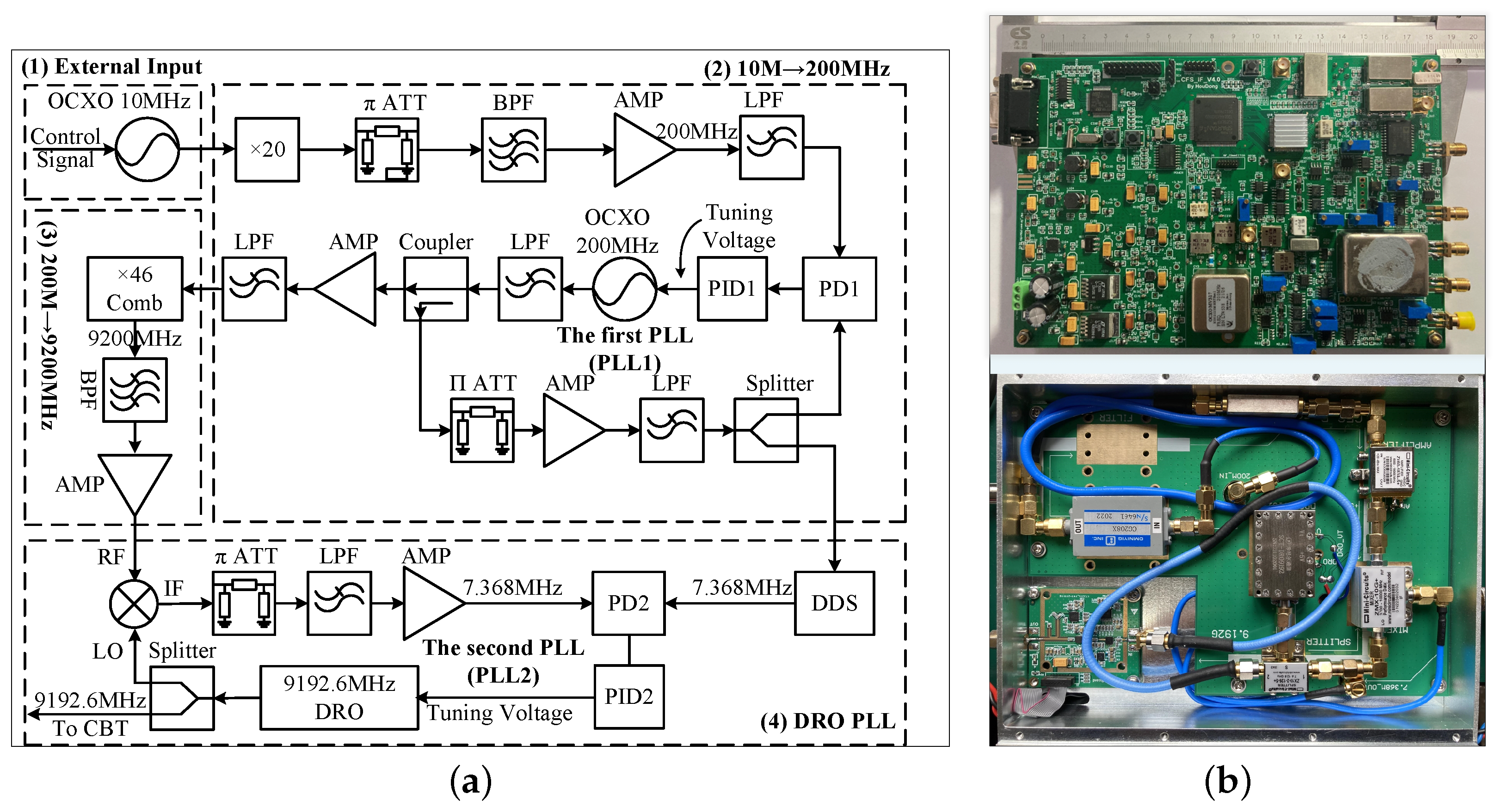
2. Schematic and Set-Up of the Frequency Synthesis Chain

Figure 1 presents the block diagram of the frequency synthesis chain, which utilizes a dual-PLL circuit. The dual-loop mode helps maintain a high phase-detector frequency and loop bandwidth in the clock generation PLL, especially when the greatest common divisor of the reference source frequency and the output clock frequency is small. This approach prevents a low phase-detector frequency and minimizes the output phase noise of the clock.
In Figure 1, a 20× frequency multiplier is used to multiply the 10 MHz reference source to 200 MHz. Then, the 200 MHz clock is phase detected with the clock output from the 200 MHz OCXO in the first phase detector (PD1) at a frequency of 200 MHz. The output signal from the 200 MHz OCXO drives a frequency comb generator to produce harmonics of 200 MHz. In the second PLL (PLL2), the 46th harmonic of 200 MHz is selected by a narrow-band bandpass filter, and then the 9.2 GHz is mixed in the second phase detector (PD2) with another 9.192 GHz produced by the DRO. By a direct digital synthesis (DDS) module, a 7.368 MHz signal is generated. Then, the 7.368 MHz and the 9.192 GHz are compared in PD2. When the two PLLs are both phase-locked, a precise frequency at 9.192 631 770 GHz is ready. Considering the frequency precision error of 10 MHz reference, the final output signal will have a certain frequency deviation.
Figure 2a illustrates a more detailed architecture diagram of the frequency synthesis chain, consisting of four main parts. Part (1) involves a 10 MHz OCXO source with ultra-low phase noise. In Part (2), a 200 MHz clock from the 20× frequency multiplier is filtered and amplified before being compared with the 200 MHz OCXO output clock in PD1. The phase error signal generated by PD1 is filtered and then fed back to the proportional–integral controller to drive the 200 MHz OCXO. The signal from the 200 MHz OCXO output is split into two paths using a coupler. In the first path, the output clock is amplified with a low-noise amplifier, filtered, and sent to PLL2 as the reference source. In the other path, the 200 MHz clock is amplified, filtered, and used to drive a comb generator. The 46th harmonic of the comb generator’s output is band-pass filtered, amplified with a microwave amplifier in part (3), and then sent to the mixer in part (4). In PLL1, a splitter is used to generate two 200 MHz signals, with one of them serving as the sampling rate of the DDS (AD9854), to generate a 7.368 230 MHz clock [20]. In part (4), the 9.2 GHz microwave generated by the comb generator is mixed with the 9.192 GHz microwave generated from the DRO, and the resultant signal is passed through a power splitter. This process generates a 7.368 230 MHz clock. The two 7.368 230 MHz clocks are compared with each other to produce a phase error signal [21,22]. The phase error signal is then low-pass filtered, conditioned by the PID2, and used to drive the DRO [19]. When the frequency synthesis chain is in a phase-locked state, the 9.192 GHz microwave is directed to an amplitude control module for precise amplitude adjustment.
The photograph of the microwave frequency synthesizer is presented in Figure 2b. The miniaturized commercial cesium beam atomic clock requires a compact and high-performance frequency synthesizer for its operation. To optimize space utilization, a two-layer stacked structure is implemented. The two circuit boards, displayed in Figure 2b, are positioned in the upper and lower layers of the shielding cavity, with a total size of 19 mm (length) × 15 mm (width) × 5.5 mm (height).
The phase noise of the output in the loop bandwidth of a PLL is primarily caused by the input reference source, following the deterioration according to the 20 × logN rule. Outside of this bandwidth, the phase noise performance is mainly determined by the internal voltage-controlled oscillator (VCO) of the PLL. In Figure 2a, PLL1 employs a narrow-loop bandwidth of 150 Hz to preserve the frequency error of the reference signal while suppressing noise from higher offset frequencies. The 200 MHz OCXO has an output power of approximately +10 dBm, a tuning sensitivity of around 50 Hz/V, and a voltage tuning range of 0 V to 8 V. Similarly, the DRO operates at an output power of approximately +15 dBm, a tuning sensitivity of about 2.2 MHz/V, and a voltage tuning range of 0 V to 9 V. It is important to note that all input and output signals are matched to 50 Ω impedance.
Given the limitations in frequency error of the 10 MHz reference source, it is essential for the final microwave signal to be precisely adjustable within a range of approximately ±1 kHz, with a high frequency resolution of less than 0.1 Hz. To achieve this level of precision, the DDS module assumes a critical role within the frequency synthesis chain. In this structure, the DDS module is integrated to generate a 7.368 MHz clock with a remarkable frequency resolution of up to 0.7 µHz [19,21]. Accurate frequency matching holds significant importance in the design of highly stable atomic clocks [23,24].

3. Theoretical Analysis and Simulation of the Frequency Synthesis Chain

3.1. Analysis of the Model for the PLLs

From control theory, the PLL phase-transfer function H(s) can be defined, which establishes a relationship between the input reference source and the output of the PLL. Figure 3 depicts a simplified configuration based on the architecture of the frequency synthesis chain shown in Figure 2a. In an analog PLL circuit, the mixer primarily functions as a phase detector.
In PLL1, as illustrated in Figure 3, the 10 MHz reference source undergoes direct multiplication by a factor of M 1 to obtain a 200 MHz clock through the use of two cascaded frequency multipliers. The resulting clock is then compared with the 200 MHz clock generated from the 200 MHz OCXO in PD1. Thus, the phase argument of the 200 MHz clock Θ m 1 ( s ) is given by
Θ m 1 ( s ) = M 1 Θ i ( s ) ,
where Θ i ( s ) represents the phase argument of the 10 MHz reference source. U e 1 ( s ) is defined as the phase error signal generated by PD1. In the complex frequency domain, U e 1 ( s ) can be expressed as
U e 1 ( s ) = k d 1 Θ e 1 ( s ) = k d 1 ( Θ o 1 ( s ) Θ m 1 ( s ) ) ,
where k d 1 denotes the detector gain of PLL1. Θ e 1 represents the phase argument of the error signal generated by PD1, while Θ o 1 ( s ) is the phase argument of the 200 MHz OCXO output. Equation (2) presents a linearized model of PD1.
The output from the 200 MHz OCXO is divided into two paths by a coupler. The main path is utilized directly, while the other path is amplified, low-pass filtered, and further divided into two additional paths. One of these paths serves as the sampling rate of the DDS, while the other is fed back to PD1. In Figure 3, the transfer function of the first loop filter is defined as F 1 ( s ) . Hence, the error signal of the filter can be expressed as
U f 1 ( s ) = F 1 ( s ) U e 1 ( s ) ,
where U f 1 ( s ) represents the error signal from the first low-pass filter (LPF1) in PLL1, which is employed to tune the 200 MHz OCXO. In the complex frequency domain, the output signal from the 200 MHz OCXO is proportional to the control signal and can be given as
Θ o 1 ( s ) = k o 1 s U f 1 ( s ) ,
where k o 1 represents the gain of the 200 MHz OCXO. When the phase error signal generated by PD1 is sufficiently small, the output signal from the mixer can be approximated by its argument. The transfer function G 1 ( s ) is defined as the first loop gain in Figure 3. Based on Equations (2)–(4), G 1 ( s ) can be expressed as
G 1 ( s ) = Θ o 1 ( s ) Θ e 1 ( s ) = k d 1 k o 1 F 1 ( s ) s ,
Furthermore, H 1 ( s ) in Figure 3 relates the input 10 MHz reference source to the 200 MHz OCXO output. H 1 ( s ) can be expressed as
H 1 ( s ) = Θ o 1 ( s ) Θ i 1 ( s ) = Θ o 1 ( s ) Θ e 1 ( s ) / M 1 = k d 1 k o 1 M 1 F 1 ( s ) s + k d 1 k o 1 F 1 ( s ) ,
Equations (5) and (6) represent the mathematical model of PLL1. Assuming that PLL1 is phase-locked in the time domain, the 200 MHz output signal u o 1 can be expressed as
u o 1 ( t ) = a 1 c o s ( ω 1 t + θ o 1 ) ,
where a 1 represents the amplitude argument of the signal, and ω 1 and θ o 1 are the radian frequency and initial phase of the 200 MHz OCXO output, respectively.
Figure 3 illustrates the utilization of the 200 MHz clock to drive a comb generator, generating harmonics of 200 MHz. We denote the order of these harmonics as M 3 , and the M 3 order of the 200 MHz harmonic as u m 3 ( t ) . Simultaneously, another 200 MHz clock serves as a sampling clock for the DDS to produce a 7.368 230 MHz clock. We denote the division factor of the DDS module as M 2 , and the signal derived from the DDS module as u m 2 ( t ) . The calculations for these two signals are as follows:
u m 2 ( t ) = a m 2 c o s 1 M 2 ω 1 t + 1 M 2 θ o 1
u m 3 ( t ) = a m 3 c o s ( M 3 ω 1 t + M 3 θ o 1 ) ,
where a m 2 and a m 3 represent the amplitude arguments of the respective signals.
In PLL2, the center frequency of the DRO is denoted as ω m 2 , and u 0 ( t ) represents the output signal of the DRO. For our design, the center frequency ω m 2 is approximately 9.192 GHz. In the time domain, u 0 ( t ) is given by the equation
u 0 ( t ) = a 0 c o s ( ω 2 t + θ 0 ) ,
where a 0 represents the amplitude and θ 0 is the initial phase of the DRO. The signal ω 2 is mixed with the 9.2 GHz signal from the comb generator to generate a clock at 7.368 MHz. This 7.368 MHz clock is then compared with the 7.368 MHz signal generated from the DDS. We define the output signal generated by the mixer as u p ( t ) :
u p ( t ) = a 0 a m 3 2 c o s ( ω 2 + M 3 ω 1 ) t + ( φ 0 + M 3 θ o 1 ) + a 0 a m 3 2 c o s ( ω 2 M 3 ω 1 ) t + ( φ 0 M 3 θ o 1 ) ,
Equation (11) describes u p ( t ) as having two parts. The first part is a higher-frequency signal, which is eliminated by a low-pass filter (LPF). The latter part represents a 7.368 MHz signal, which is compared with the 7.368 MHz signal from the DDS in PD2. The phase argument of the error signal generated by PD2 is denoted as θ e 2 ( s ) . In the complex frequency domain, based on Equations (7)–(11), the phase error signal θ e 2 ( s ) of PD2 can be expressed as
θ e 2 ( s ) = θ 0 ( s ) M + a 0 a m 3 2 c o s ( ω 2 M 3 ω 1 ) t + ( φ 0 M 3 θ o 1 ) ,
where θ 0 ( s ) represents the phase argument of the DRO output. The transfer function G 2 ( s ) is defined as the loop gain of PLL2 shown in Figure 3. Thus, the phase argument of the DRO output Θ 0 ( s ) can be expressed as
Θ o ( s ) = k o 2 s U f 2 ( s ) = k o 2 s F 2 ( s ) k d 2 Θ e 2 ( s ) = k o 2 s F 2 ( s ) k d 2 Θ o ( s ) M 3 + 1 M 2 Θ o 1 ( s ) ,
In Equation (13), k d 2 represents the detector gain of the DRO, k o 2 is the DRO gain, and F 2 ( s ) is the transfer function of the second loop filter in PLL2. Consequently, the phase-closed loop transfer function F 2 ( s ) of PLL2 can be derived as
H 2 ( s ) = Θ o ( s ) Θ o 1 ( s ) ,
Based on the aforementioned analysis, the phase-closed loop transfer function of the microwave frequency synthesis chain H ( s ) can be expressed as
H ( s ) = H 1 ( s ) H 2 ( s ) = k d 1 k d 2 k o 1 k o 2 M 1 M 2 M 3 F 1 ( s ) F 2 ( s ) + k d 1 k d 2 k o 1 k o 2 M 1 F 1 ( s ) F 2 ( s ) M 2 s 2 + M 2 k d 1 k o 1 F 1 ( s ) + k d 2 k o 2 F 2 ( s ) s + M 2 k d 1 k d 2 k o 1 k o 2 F 1 ( s ) F 2 ( s ) ,
In Figure 4, an active loop filter is utilized, with a transfer function gain of k p ( 1 / T i + 1 ) , where k p and T i represent the gain and integration time of the loop filter, respectively. In this paper, a first-order passive LPF is employed, and its transfer function can be expressed as L ( s ) = 1 / ( τ s + 1 ) , where τ denotes the time delay of the LPF. For our design, only the proportional gain is utilized in the proportional–integral (PI) regulator as shown in Figure 2. Consequently, k p ( 1 / T i + 1 ) can be simplified to k p . Additionally, the transfer function mode of an active loop filter can be expressed as F ( s ) = k p / ( τ s + 1 ) . Therefore, we have
F 1 ( s ) = k p 1 / ( τ 1 s + 1 ) ,
F 2 ( s ) = k p 2 / ( τ 2 s + 1 ) ,

3.2. Simulation Results

3.2.1. Transient Analysis

The PLL ensures the phase alignment of the output clock with the reference source. Although the phase of the reference source can experience instantaneous distortion, the PLL requires a certain amount of time to adjust its phase. Thus, the phase-settling time plays a crucial role in evaluating the frequency synthesizer [25]. Simulations of H ( s ) using Equation (15) were conducted based on the theory presented in Section 2. The parameter values used are as follows: M 1 = 20, M 2 = 200/7.36823, M 3 = 46, k d 1 = 1 V/rad, k d 2 = 1 V/rad, k o 1 = 90 Hz/V, and k o 1 = 2.2 MHz/V. Since the frequency synthesizer consists of two PLLs, the parameters k p and τ can be adjusted for both PLLs.
Assuming that the parameters k p 2 and τ 2 are fixed simplifies the calculation of the modulation signal gain applied in the frequency synthesis chain. The given parameter values were substituted into Equation (15), and the step responses of the system are depicted in Figure 5. Figure 5a illustrates the settling times of the phase step response for various values of k p 1 (ranging from 2 to 4 in step of 2/3), while τ 1 remains fixed at 2 × 10 4 s. The settling times obtained are 1.52 ms, 1.07 ms, 822 µs, and 674 µs, respectively. For comparison, Figure 5b demonstrates the effect of varying τ 1 (ranging from 2 × 10 4 s to 8 × 10 4 s) while k p 1 remains fixed at 2.
The simulation results indicate that increasing k p 1 leads to a decrease in the settling time of the signal. Conversely, keeping k p 1 constant and increasing τ 1 results in an increase in both the overshoot and settling time of the signal. Therefore, reducing τ 1 not only shortens the transient response duration but also suppresses phase fluctuations. However, reducing τ 1 widens the bandwidth of the active loop filter, which introduces more noise. Hence, for practical design purposes, the loop filter gain k p 1 should be appropriately increased, while τ 1 is appropriately decreased.
Figure 6 demonstrates that varying parameter k p 2 has a minimal effect on the settling time. Thus, the settling time of the frequency synthesizer is primarily determined by PLL1.

3.2.2. Stability Analysis

The impact of the loop filtering parameters of PLL1 on the transient characteristics and system stability is evident from the analysis in Section 3. Bode plots illustrating the frequency domain with the application of an external modulation signal are presented in Figure 7.
Figure 7a indicates that when the τ 1 parameter is fixed, increasing the loop filter gain k p 1 leads to an increase in the gain margin, phase margin, and stability. Conversely, Figure 7b demonstrates that when the k p 1 parameter is fixed, an increase in τ 1 results in a decrease in the gain margin, phase margin, and stability. System stability is maintained when the modulation frequency is below 150 Hz (equivalent to 150 × 2 π rad/s), as the phase deviation between the stepping signal and the reference source remains close to zero. However, when the modulation frequency exceeds 150 Hz, the phase gain starts to decrease. As the modulation frequency increases, the phase gain decays rapidly, leading to reduced system stability. Based on the simulation results, the following guidelines for setting parameters k p 1 and τ 1 are recommended:
( 1 ) Moderately increasing k p 1 optimizes the settling time.
( 2 ) Parameter τ 1 should be adjusted in combination with parameter k o 1 . An appropriate reduction in parameter τ 1 enhances the settling time and effectively suppresses overshoot.

4. Experimental Results and Verification

4.1. Settling Time Measurement

The configuration of the phase setting measurement is simplified to a functional block as depicted in Figure 8. A dual-channel arbitrary function generator (AFG; Tektronix AFG3022B) is employed as the phase shifter here. Figure 8 illustrates that the AFG utilizes the 10 MHz OCXO as a reference to generate two identical 10 MHz signals, which are then used to drive the two frequency synthesizers (FSs) for generating two cesium atomic resonant frequencies at 9.192 631 770 GHz. One of the FSs proposed in this paper is denoted as FSA, while the other is a commercial microwave signal synthesizer (FSB; SMB100A, Rohde and Schwarz).
The 10 MHz signal generated by the AWG can be phase modulated to simulate the phase step function, allowing the FSs to experience a phase step by utilizing the phase shift produced by the AWG. Phase modulation is applied to FSA to generate the phase step, while maintaining a fixed phase in FSB. Since the two 9.192 GHz signals are simultaneously phase-locked to the same 10 MHz reference source, their phases are precisely synchronized. The two signals are compared in a mixer (Mini-circuits, ZMX-10G+), and the resulting phase error signal is recorded using a digital storage oscilloscope. In accordance with the mixer principle described in Section 3.1, the higher-frequency output from the mixer is eliminated due to the bandwidth limitation of the oscilloscope, while the lower-frequency component is retained. When the phase step signal is applied to FSA, the mixer output signal is recorded, and the settling time of the step response is measured to assess the phase-settling ability.
When the phase shift signal is applied to the 10 MHz reference source of FSA, the phase response affecting the frequency of 9.192 631 770 GHz is multiplied by 919.2. Consequently, the minimum phase shift of the AWG is 0.01 , resulting in an approximate 9.192 phase shift at 9.192 631 770 GHz. The remarkable property of the DDS in an FS, as per the DDS principle, is the agility of the phase shift. Therefore, in comparison with the phase shift time, the phase-settling time is insignificantly short and can be disregarded.
When FSA and FSB are simultaneously phase-locked to the same 10 MHz reference clock, as depicted in Figure 8, the output signal from the mixer becomes a direct current (DC) signal. We adjust the phase of FSA until the DC signal reaches its maximum negative value. The phase step is applied within the range of π , resulting in an approximate phase shift of 0.2 applied to the 10 MHz reference. The measured values are compared with the simulation results under the same conditions as shown in Figure 9. The dotted lines represent the simulation results, while the solid lines depict the results obtained using the configuration described in Figure 8.
Figure 9 illustrates the phase step response for various values of the loop filter gain k p 1 . As the k p 1 parameter increases from 2 to 4 in step of 2/3, the measured settling times are 1.5 ms, 1.064 ms, 825.5 µs, and 644.5 µs, respectively. The measured results align with the simulated results, providing evidence that the theoretical calculation for the transfer function of the synthesis and the experimental setup for measuring the phase step response are accurate and reasonable. The parameter adjustment and simulation results in Figure 9 are consistent with those in Figure 5a. Parameter k p 1 represents the gain of the PLLI loop filter. In our design, an adjustable sliding rheostat is employed to modify the gain of the PLLI loop filter.

4.2. Phase Noise Measurement

Figure 10 presents the absolute phase noise measurements for a frequency synthesis chain consisting of a 10 MHz OCXO, a 200 MHz OCXO, and a DRO. The phase noise measurements were conducted using the R&S FSWP26. As discussed in Section 3, PLL1 and PLL2 were set with bandwidths of 150 Hz and 300 kHz, respectively. Figure 10a illustrates the absolute phase noises of the 10 MHz OCXO, which are measured at −123.8 dBc/Hz, −137.5 dBc/Hz, −158.5 dBc/Hz, and −165.5 dBc/Hz at 1 Hz, 10 Hz, 1 kHz, and 10 kHz offset frequencies, respectively. The output clock of the 200 MHz OCXO in its free-running state was measured at a power level of approximately +26 dBm, using a signal passed through a directional coupler and amplifier. The absolute phase noises at 1 Hz, 10 Hz, 1 kHz, and 10 kHz offsets were recorded as −56.5 dBc/Hz, −93.2 dBc/Hz, −145.3 dBc/Hz, and −163.6 dBc/Hz, respectively (see Figure 10c). While PLL1 was locked, the absolute phase noises of the 200 MHz OCXO signal were observed to be −97.5 dBc/Hz, −110.1 dBc/Hz, −145.0 dBc/Hz, and −163.8 dBc/Hz at 1 Hz, 10 Hz, 1 kHz, and 10 kHz offset frequencies, respectively (see Figure 10b). Comparing Figure 10c and Figure 10b, it is evident that the phase noise performance exhibits an improvement of approximately 40 dB around the 1 Hz offset frequency at a carrier frequency of 200 MHz. In PLL1, a narrow-loop bandwidth of around 150 Hz was employed to suppress higher offset frequency phase noise while ensuring low phase noise performance for PLL2. As a result, PLL2 can operate with a moderate loop bandwidth of 300 kHz.
The selection of the loop bandwidth for PLL2 aims to combine the superior high-offset frequency phase noise characteristics of the DRO with the favorable low-offset frequency phase noise of the 200 MHz OCXO. When the DRO operates in a free-running state as depicted in Figure 10e, the phase noises are recorded as −66.2 dBc/Hz and −88.3 dBc/Hz at 1 kHz and 10 kHz offsets, respectively. Figure 10d illustrates the phase noises at 9.192 GHz when the frequency synthesis chain is locked, which are measured as −63.7 dBc/Hz, −75.7 dBc/Hz, −107.1 dBc/Hz, and −122.5 dBc/Hz at 1 Hz, 10 Hz, 1 kHz, and 10 kHz offset frequencies, respectively. Our absolute phase noise performance has an advantage, especially at the frequency offset of 1 Hz. However, for the phase noise of the frequency synthesizer, it should be evaluated based on the actual deterioration degree, using the reference source as a benchmark. Notably, from Figure 10e, it can be observed that the phase noises at 1 Hz and 10 Hz offsets, with a carrier frequency of 9.192 GHz, are only 0.8 dB and 2.5 dB worse than the 20 logN rule derived from the 10 MHz reference source. Consequently, the frequency synthesizer demonstrates favorable phase noise performance at low offset frequencies below 150 Hz.
In Figure 10d, the phase noise plot exhibits two inflection points around the offset frequencies corresponding to the two loop bandwidths. By appropriately increasing the loop bandwidths of both PLLs, a significant improvement in the phase noise performance can be achieved for offset frequencies lower than the bandwidths. However, a higher loop bandwidth results in more accumulated noise. Therefore, both loop bandwidths in the frequency synthesizer should be selected appropriately.

5. Conclusions

We constructed a high-performance microwave frequency synthesizer using a dual-loop PLL architecture in the context of a cesium-beam atomic clock application. This architecture provides excellent phase noise performance and a suitable settling time. PLL1 is driven by an external 10 MHz reference source, generating a precise and low-jitter 200 MHz frequency signal that acts as the reference driver clock for PLL2. We achieved ultra-low phase noise by allowing the OCXO to dominate the phase noise at low offsets, while the phase noise of the DRO remained dominant at high offsets. The absolute phase noise levels at 9.192 631 770 GHz were measured at −63.7, −75.7, −107.1, and −122.5 dBc/Hz at 1 Hz, 10 Hz, 1 kHz, and 10 kHz offset frequencies, respectively. Furthermore, a mathematical model was established and analyzed. The phase-settling time was theoretically analyzed and verified through simulations, showing agreement with the actual measurements. Our work will be useful for the design of a compact, high-performance frequency synthesizer for different atomic clock applications.

Author Contributions

Conceptualization, D.H. and F.S.; methodology, D.H.; software, G.G. and D.H.; validation, G.G., C.L. and K.L.; formal analysis, G.G.; investigation, D.H. and G.G.; resources, F.S. and C.L.; data curation, G.G. and C.L.; writing—original draft preparation, G.G.; writing—review and editing, F.S. and D.H.; visualization, G.G. and D.H.; supervision, D.H., F.S. and S.Z.; project administration, F.S.; funding acquisition, F.S. and S.Z. All authors have read and agreed to the published version of the manuscript.

Funding

This research was funded by the National Natural Science Foundation of China, grant number 62271109, the Natural Science Foundation of Sichuan Province, grant number 2023NSFSC0445, the Equipment Advance Research Field Foundation, grant numbers 315067207 and 315067206, the Fundamental Research Funds for the Central Universities of China, grant number ZYGX2021J019, and State Key Laboratory of Advanced Optical Communication Systems Networks, China, grant number 2023GZKF09.

Institutional Review Board Statement

Not applicable.

Informed Consent Statement

Not applicable.

Data Availability Statement

Not applicable.

Conflicts of Interest

The authors declare no conflict of interest.

References

  1. Gill, P. Raising the standards. Science 2001, 294, 1666–1668. [Google Scholar] [CrossRef]
  2. Mohr, P.J.; Newell, D.B.; Taylor, B.N.; Tiesinga, E. Data and analysis for the CODATA 2017 special fundamental constants adjustment. Metrologia 2018, 55, 125–146. [Google Scholar] [CrossRef] [Green Version]
  3. Lodewyck, J. On a definition of the SI second with a set of optical clock transitions. Metrologia 2019, 56, 055009. [Google Scholar] [CrossRef]
  4. Li, C.; Sun, F.; Liu, J.; Li, X.; Ma, J.; Guo, G.; Hou, D.; Zhang, S. Non 0–0 states magnetically insensitive transitions in alkali species. Phys. Scr. 2020, 95, 045402. [Google Scholar] [CrossRef]
  5. Guo, G.; Liu, J.; Hou, D.; Liu, K.; Wang, H.; Huang, X.; Ma, J.; Sun, F. Dual-mode Ramsey microwave cavity for a dual Rb/Cs atomic clock. Electron. Lett. 2018, 54, 632–634. [Google Scholar] [CrossRef]
  6. Hafele, J.C.; Keating, R.E. Around-the-world atomic clocks: Observed relativistic time gains. Science 1972, 177, 168–170. [Google Scholar] [PubMed]
  7. McGrew, W.; Zhang, X.; Fasano, R.; Schäffer, S.; Beloy, K.; Nicolodi, D.; Brown, R.; Hinkley, N.; Milani, G.; Schioppo, M.; et al. Atomic clock performance enabling geodesy below the centimetre level. Nature 2018, 564, 87–90. [Google Scholar] [CrossRef] [Green Version]
  8. Knappe, S.; Alem, O.; Sheng, D.; Kitching, J. Microfabricated optically-pumped magnetometers for biomagnetic applications. J. Phys. Conf. Ser. 2016, 723, 012055. [Google Scholar] [CrossRef]
  9. Boudot, R.; Guérandel, S.; De Clercq, E. Simple-design low-noise NLTL-based frequency synthesizers for a CPT Cs clock. IEEE Trans. Instrum. Meas. 2009, 58, 3659–3665. [Google Scholar] [CrossRef]
  10. Vanier, J. Atomic clocks based on coherent population trapping: A review. Appl. Phys. B 2005, 81, 421–442. [Google Scholar] [CrossRef]
  11. Santarelli, G.; Audoin, C.; Makdissi, A.; Laurent, P.; Dick, G.J.; Clairon, A. Frequency stability degradation of an oscillator slaved to a periodically interrogated atomic resonator. IEEE Trans. Ultrason. Ferroelectr. Freq. Control 1998, 45, 887–894. [Google Scholar] [CrossRef]
  12. Karlquist, R.K. A new RF architecture for cesium frequency standards. In Proceedings of the 1992 IEEE Frequency Control Symposium, Hershey, PA, USA, 27–29 May 1992; IEEE: Piscataway, NJ, USA, 1992; pp. 134–142. [Google Scholar]
  13. Cutler, L.S.; Giffard, R.P. Architecture and algorithms for new cesium beam frequency standard electronics. In Proceedings of the 1992 IEEE Frequency Control Symposium, Hershey, PA, USA, 27–29 May 1992; IEEE: Piscataway, NJ, USA, 1992; pp. 127–133. [Google Scholar]
  14. Francois, B.; Calosso, C.; Danet, J.; Boudot, R. A low phase noise microwave frequency synthesis for a high-performance cesium vapor cell atomic clock. Rev. Sci. Instrum. 2014, 85, 094709. [Google Scholar] [CrossRef]
  15. François, B.; Calosso, C.; Abdel Hafiz, M.; Micalizio, S.; Boudot, R. Simple-design ultra-low phase noise microwave frequency synthesizers for high-performing Cs and Rb vapor-cell atomic clocks. Rev. Sci. Instrum. 2015, 86, 094707. [Google Scholar] [CrossRef]
  16. Audoin, C. A limit to the frequency stability of passive frequency standards due to an intermodulation effect. IEEE Trans. Instrum. Meas. 1991, 40, 121–125. [Google Scholar] [CrossRef]
  17. Ju, B.; Yun, P.; Hao, Q.; Nie, S.; Liu, G. A low phase and amplitude noise microwave source for vapor cell atomic clocks. Rev. Sci. Instrum. 2022, 93, 104709. [Google Scholar] [CrossRef]
  18. Danet, J.M.; Lours, M.; Guérandel, S.; De Clercq, E. Dick effect in a pulsed atomic clock using coherent population trapping. IEEE Trans. Ultrason. Ferroelectr. Freq. Control 2014, 61, 567–574. [Google Scholar] [CrossRef] [Green Version]
  19. Petrov, A.; Davydov, V. Digital frequency synthesizer for 133 Cs-vapor atomic clock. J. Commun. Technol. Electron. 2017, 62, 289–293. [Google Scholar] [CrossRef]
  20. Du, Y.; Li, W.; Ge, Y.; Li, H.; Deng, K.; Lu, Z. Note: A high-frequency signal generator based on direct digital synthesizer and field-programmable gate array. Rev. Sci. Instrum. 2017, 88, 096103. [Google Scholar]
  21. Liu, K.; Tian, S.; Guo, G.; Xiao, Y. Precisely synchronous and cascadable multi-channel arbitrary waveform generator. Rev. Sci. Instrum. 2017, 88, 035110. [Google Scholar] [CrossRef]
  22. Didier, A.; Millo, J.; Grop, S.; Dubois, B.; Bigler, E.; Rubiola, E.; Lacroûte, C.; Kersalé, Y. Ultra-low phase noise all-optical microwave generation setup based on commercial devices. Appl. Opt. 2015, 54, 3682–3686. [Google Scholar]
  23. Dick, G.J. Local oscillator induced instabilities in trapped ion frequency standards. In Proceedings of the 19th Annual Precise Time and Time Interval Systems and Applications Meeting, Redondo Beach, CA, USA, 1–3 December 1989; pp. 133–147. [Google Scholar]
  24. Nelson, C.W.; Hati, A.; Nava, J.; Howe, D.A. Phase noise suppression in frequency comb generators. In Proceedings of the 2010 IEEE International Frequency Control Symposium, Newport Beach, CA, USA, 1–4 June 2010; IEEE: Piscataway, NJ, USA, 2010; pp. 440–442. [Google Scholar]
  25. Bin, L. A decision-feedback phase-tracking receiver for continuous phase modulation. IEEE Trans. Commun. 1997, 45, 396–399. [Google Scholar] [CrossRef]
Figure 1. Basic architecture of the frequency synthesis chain.
Applsci 13 09155 g001
Figure 2. (a): The set-up of the frequency synthesis chain, (b): a photograph of the microwave frequency synthesizer. In (a), Part (1): 10 MHz OCXO. Part (2): the first PLL, including 20× frequency multiplier. Part (3): 200 MHz to 9.2 GHz. Part (4): the second PLL, including the DRO. OCXO, oven-controlled crystal oscillators; DRO, dielectric resonant oscillator; AMP, amplifier; ATT, attenuator; PD, phase detector; PID, proportional–integral–derivative controller; LPF, low-pass filter; BPF, band-pass filter.
Applsci 13 09155 g002
Figure 3. Mathematical model of the frequency synthesis chain.
Applsci 13 09155 g003
Figure 4. Functional block diagram of the active loop filter PLL.
Applsci 13 09155 g004
Figure 5. Simulation results showing the phase step response. (a) Parameter τ 1 was fixed, while parameter k p 1 was varied. (b) Parameter k p 1 was fixed, while parameter τ 1 was varied.
Applsci 13 09155 g005
Figure 6. Simulation results showing the phase step response. Parameter τ 2 was fixed, and parameter k p 2 was varied.
Applsci 13 09155 g006
Figure 7. Bode diagrams: (a) τ 1 = 2 × 10 4 s and k p 1 from 2 to 4 and (b) k p 1 = 4 and τ 1 from 2 × 10 4 s to 4 × 10 4 s.
Applsci 13 09155 g007
Figure 8. Simplified configuration for measuring the phase-settling ability.
Applsci 13 09155 g008
Figure 9. Comparison of phase step response measurements. τ 1 is maintained at 2 × 10 4 s. The subfigures are labeled as follows: (a) k p 1 = 2; (b) k p 1 = 8/3; (c) k p 1 = 10/3; (d) k p 1 = 4; The simulation results are depicted using dotted lines, and the measurement results are denoted by solid lines.
Applsci 13 09155 g009aApplsci 13 09155 g009b
Figure 10. Absolute phase noise measurement. (a) 10 MHz OCXO, (b) 200 MHz phase locked to 10 MHz, (c) 200 MHz OCXO free running, (d) 9.192 GHz phase locked to 10 MHz, (e) free-running DRO.
Applsci 13 09155 g010
Disclaimer/Publisher’s Note: The statements, opinions and data contained in all publications are solely those of the individual author(s) and contributor(s) and not of MDPI and/or the editor(s). MDPI and/or the editor(s) disclaim responsibility for any injury to people or property resulting from any ideas, methods, instructions or products referred to in the content.

