Article

Influence of Cavitation and Shaft Deformation in the Analysis of Lubrication of the Stern Bearing

1
Wuhan Second Ship Design Institute, Wuhan 430205, China
2
School of Automotive Engineering, Dalian University of Technology, Dalian 116024, China
3
State Key Laboratory of Structural Analysis for Industrial Equipment, Dalian University of Technology, Dalian 116024, China
*
Author to whom correspondence should be addressed.
Appl. Sci. 2023, 13(15), 9033; https://doi.org/10.3390/app13159033
Submission received: 15 June 2023 / Revised: 4 August 2023 / Accepted: 4 August 2023 / Published: 7 August 2023
(This article belongs to the Special Issue Tribological Properties of Engine and Transmission)

Abstract

:
The cavitation phenomenon and shaft deformation have a significant impact on the tribological performance of the journal bearing. A mixed lubrication model is developed that takes into account surface roughness and asperity contact, as well as the effects of cavitation and deflection. The fluid–solid coupling effect in bearing deformation, asperity contact, and film pressure are investigated. The effect of boundary conditions on the lubrication regimes is discussed. The results of simulations with and without cavitation are compared under steady-state conditions. The results show that when cavitation is considered by the mixed lubrication model under a given load, the eccentricity is reduced, and the maximum oil film pressure is also reduced. The speed range of the bearing simulated with the mixed lubrication model increases after considering deflection deformation. The mixed lubrication model proposed in this paper is able to provide accurate results of pressure distribution and coefficient of friction and can be applied in the design and analysis of journal bearings.

1. Introduction

The stern tube journal bearing is an essential component of a ship’s power system, and its lubrication performance directly affects the driving efficiency and stability of the ship’s power system [1]. The liquid film distribution in plain bearings is the key factor that determines the bearing’s lubrication performance. In dynamic load bearings, the fracture zone of the liquid film is constantly changing due to the continuous movement of the journal, which has an impact on the subsequently established bearing oil film. Therefore, determining the starting and ending points of the oil film and accurately describing oil film pressure are always complex and important problems.
The Reynolds boundary condition is widely used in the simulation of oil films [2,3], but the mass conservation condition of the oil film reformation boundary is not taken into consideration, so the situation of oil film reformation cannot be explained correctly. Jacobson [4] and Olsson [5] derived the JFO (Jacobson–Floberg–Olsson) theory of the cavitation boundary from the mass conservation of flow and obtained the mass conservation boundary condition. JFO theory is an improvement of the Reynolds boundary condition because it not only describes the cavitation condition of oil film but also considers the mass conservation condition during oil film reformation, so the JFO theory is well-suited for the actual situation of oil film [6]. Narwat et al. developed a numerical model for the simulation of cavitation in oscillatory porous squeeze film, analyzed different cavitation calculation methods, and found that JFO boundary conditions can best explain the gaseous cavitation on a dimpled surface [7].
The cavitation effect in oil film is an important issue in research on bearing lubrication performance [8]. Floberg experimentally demonstrated that the cavity pressure is almost constant in a large dynamic bearing [9]. Subsequently, Pan [10] developed this theory and proved that it is also applicable to the non-slip flow of fluid in the cavitation region. Brewe [11] used the multigrid method in the analysis of dynamic load bearings, and Kumar [12] proposed the finite element analysis method of bearing lubrication. Elrod [13] proposed the use of the generalized Reynolds equation in finite difference formulation according to JFO theory. Their formulation is suitable for both cavitation lubrication and lubrication with a full oil film. This formulation is called the mass-conserving cavitation algorithm, which overcomes the difficulty of numerical realization of JFO theory. Vijayarghavan et al. [14] studied the cavitation boundary condition of asymmetric bearings with grooves of finite length based on this method. Vincent et al. [15] used this method to solve the lubrication problem of non-circular bearings.
Numerical methods considering cavitation in lubricated journal bearings have been widely investigated. Tucker et al. proposed a full three-dimensional thermohydrodynamic CFD approach to journal bearings and considered cavitation modelling based on averaged lubricant/vapor properties [16]. In their method, the pressures in the cavitation zone are not set directly, enabling subambient pressures to be predicted. Yan et al. considered cavitation wear and observed significant differences in the mechanisms of wear in different materials [17]. Flores et al. investigated lubricated joints in constrained rigid multibody systems and developed a general methodology for modeling [18]. Song et al. established a numerical model that can be used to accurately predict the cavitation phenomenon and performance of hydrodynamic bearings under steady state and verified the results under different working conditions [19]. Shahmohamadi et al. presented a mixed solution of the Navier–Stokes continuity and energy equations for multiphase flow conditionsand also considered the vapor transport equation to ensure continuity of flow in the cavitation region [20]. The effect of cylinder deactivation upon engine bearing efficiency has bee studied as an application of the method. Wang et al. [21] proved that the rotational speed is important in determining the cavitation boundary conditions of the oil film through theoretical and experimental studies. Jiang et al. [22] proposed an analytical approach to optimize the textured bearing with cavitation, and Zhang et al. [23] further obtained a general equation based on the incompressibility of fluids. Xu et al. compared the Reynolds boundary condition with JFO theory to study the influence of cavitation theory on bearings with a stable load [24]. Ding et al. established a gas cavitation model that can be applied to non-equilibrium cavitation simulation based on Bunsen solubility and bubble dynamics [25]. Sobhi et al. proposed an efficient numerical approach for the simulation of the effects of cavitation and non-Newtonian behavior on the performance of squeeze film [26] and found that the anisotropic structure of the porous surface decreases the pressure in the porous disc [27].
The deflection of the stern shaft will inevitably affect the oil film distribution, causing changes in bearing lubrication characteristics and dynamic characteristics. Tieu et al. [28] proved that controlled elastic deflection of the journal bearing improves the carrying capacity of the bearing and reduces friction. Liu et al. [29] investigated the effect of deflection on the load-bearing characteristics of the permanent magnet bearing and proved that deflection is a critical factor for load bearing. He et al. investigated the influences of cavitation and different boundary conditions on the Stribeck curves of stern bearings [30]. The influence of surface roughness on the lubrication status of hydrodynamic bearings is also important. Generally, the effect of surface roughness is treated as a random variable [31], while the contact and lubrication model with micro-convex, which can be modeled through surface scanning, gives a more accurate description of contact force. Mishra et al. conducted a comprehensive survey of hydrodynamic bearings and investigated the influence of rough surfaces in big-end bearings [32]. They also discussed the influence of different roughness patterns. The transverse, longitudinal, and isotropic roughness patterns in bearings were considered.
In this paper, based on the cavitation algorithm of mass conservation and the introduction of the micro-convex contact model, a mixed lubrication model of bearings considering shaft deflection and cavitation effect is established. The influence of cavitation and shaft deflection on the lubrication state is analyzed. The proposed algorithm presents a numerical model considering the property of liquid film, the deformation of bearings, and surface roughness. The fluid–solid coupling effect in bearing deformation, asperity contact, and film pressure are investigated. The proposed algorithm is suitable for describing the behavior of lubricated journal bearings.

2. Governing Equations of Lubrication Model

In this section, the governing equations of the lubrication model that describe the state of the shaft and bearing are discussed. First, the force balance equation of the shaft is established, considering the external load, film pressure, and the contact force of the micro-convex body. Then, a friction model is presented to describe the friction force between the bearing and the shaft. Finally, a mixed lubrication model considering surface roughness is presented to describe the state in the liquid film.

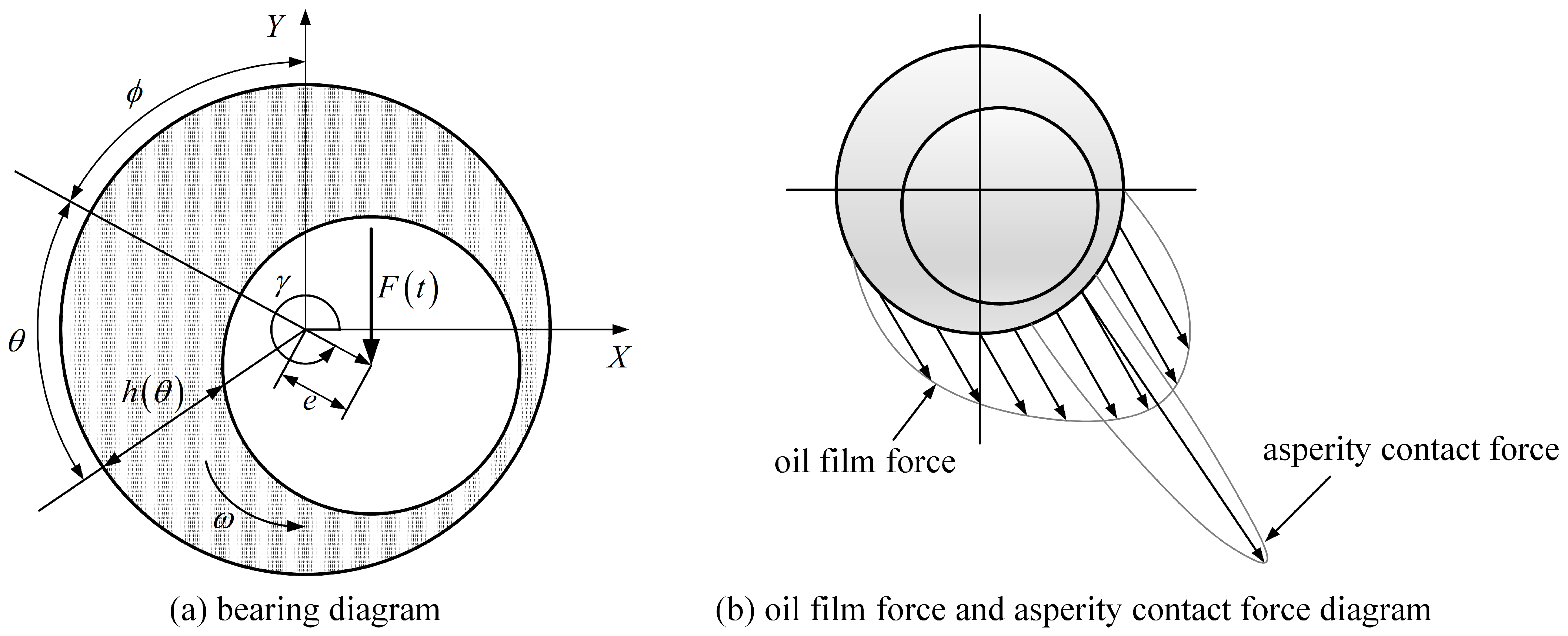
2.1. Force Balance Model of Shaft

To facilitate the analysis of lubrication characteristics of the bearing, a two-dimensional section of the bearing is taken under consideration. The force on the journal is shown in Figure 1. Ignoring the influence of inertia in oil film, the force balance condition of the bearing journal in stable operation is formulated as follows:
0 L 0 2 π p cos θ + ϕ d θ d z + F x + W x = 0
0 L 0 2 π p sin θ + ϕ d θ d z + F y + W y = 0
where p is the oil film pressure; F x , W x and F y , W y are the components of the external load and the contact force on the bearing in the x and y directions, respectively; and W A is defined as the module of the contact force, which can be calculated as
W A = W x 2 + W y 2
where W A is determined by the contact model of the micro-convex body between the bearing and the stern shaft. The contact stiffness of a single micro-convex can be calculated through the Hertz elastic contact theory. The elastic contact force on a single micro-convex is calculated as
p m c = 4 E e q R 3 δ a 3 / 2
where E e q represents the equivalent elastic modulus. Assuming that the height of a micro-convex on rough surfaces follows a Gaussian distribution with a standard deviation, the normal contact load and normal contact stiffness of the joint can be obtained using probability theory and statistical methods.
F e is defined as the module of external load on the stern shaft.
F e = F x 2 + F y 2
Its size is determined by the working condition of the bearing. ϕ represents the angle between the bearing center and the connecting line of the shaft center and the Y axis. The position relation is shown in Figure 1a, and the distribution of the fluid film pressure and the contact force of the micro-convex body is shown in Figure 1b.
The liquid film force in the x and y directions ( F o i l x and F o i l y ) can be calculated as
F o i l x = 0 L 0 2 π p cos θ + ϕ d θ d z
F o i l y = 0 L 0 2 π p sin θ + ϕ d θ d z

2.2. Coefficient of Friction

The friction between the bearing and shaft is composed of fluid lubrication viscous friction and asperity peak contact friction, which can be expressed as:
F = f o i l , f r c + f a s p , f r c
The fluid lubrication viscous friction ( f o i l , f r c ) and asperity peak contact friction ( f a s p , f r c ) are [33]:
f o i l , f r c = 0 l 0 2 π h 2 p R θ + U η h R d θ d z
f a s p , f r c = μ f W a s p
W a s p = 0 l 0 2 π p a h d θ d z

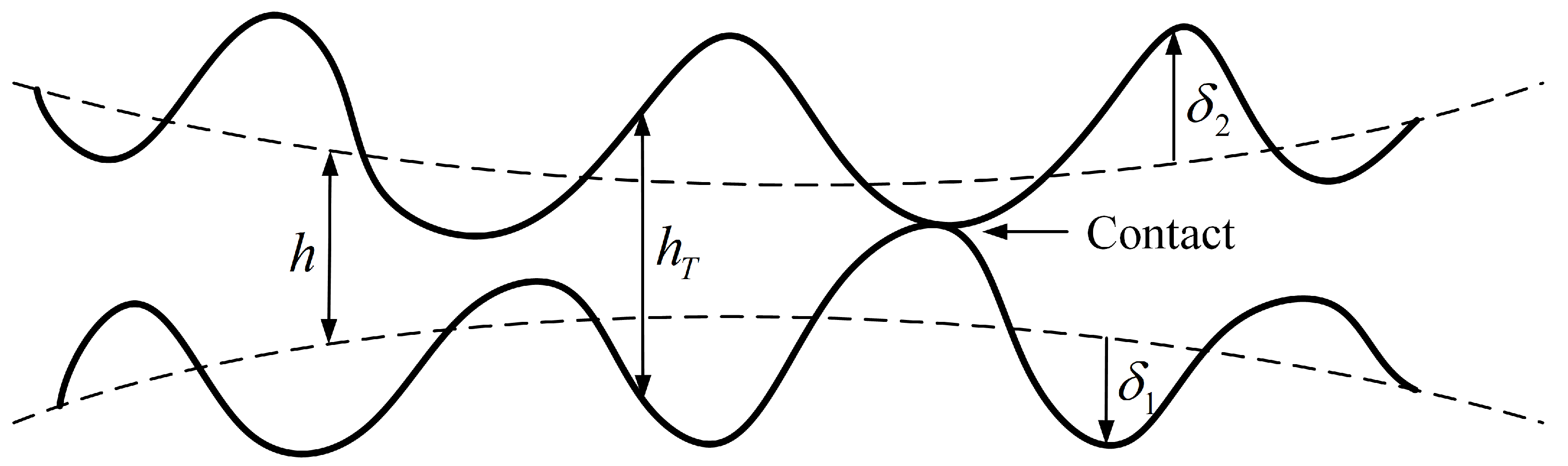
2.3. Mixed Lubrication Model Considering Surface Roughness

The morphological characteristics of the lubricating surface (as shown in Figure 2) affect the status of the oil film, which must be considered in the analysis of hydrodynamic lubrication. According to the rough surface contact theory proposed by J.A.Greenweed and J.H.Tripp [34], the film thickness ratio (H) is used as a measure of the lubrication state:
H = h / σ
where h represents the mean square value of the oil film thickness between the surfaces, and σ represents the surface profile height. When the film thickness ratio is less than 4, the bearing is in a mixed lubrication state. With an increase in the film thickness ratio, the contact micro-convex is gradually separated. When the film thickness ratio is greater than 4, it can be considered that the contact part is completely separated. The mean flow model proposed by Patir Nadir and Cheng H.S. [35] was introduced to describe the lubrication-governing equation of a shaft-bearing system considering lubrication surface topography characteristics, which can be expressed as:
θ ϕ x ρ h 3 P θ + R 2 z ϕ z ρ h 3 P z = 6 μ ρ U R ( h ¯ θ + σ ϕ s θ )
where h is the nominal oil film thickness, which refers to the oil film thickness between two surfaces without considering the surface roughness; h T refers to the actual oil film thickness between two surfaces when surface roughness is considered, as shown in Figure 2; and h ¯ T is the actual average oil film thickness:
h ¯ T = E h T
where E represents the mathematical expectation, μ is lubricating oil viscosity, U is the relative linear velocity of the shaft and bearing, ϕ x and ϕ z represent the pressure flow factors, and ϕ s is the shear flow factor. As shown in Figure 2, when the distribution characteristics of surface roughness are determined, h ¯ T is a function of h. According to the derivative rule of complex functions, Equation (15) can be obtained:
h ¯ T θ = h ¯ T h h θ
The dimensionless parameter proposed by Wu et al. [36] is adopted to define the contact factor ( ϕ c ):
ϕ c = h ¯ T h
The asperity heights are assumed to vary randomly with a certain probability distribution. The density function of distribution of roughness is φ ( s ) ; then:
ϕ c = H + φ s d s
Assume that the contact factors are distributed according to the following Gaussian equation:
φ ( s ) = 1 2 π exp s 2 2
Substitute Equation (18) into Equation (17):
ϕ c = H 1 2 π exp s 2 2 d s = H 0 1 2 π exp s 2 2 d s + 0 1 2 π exp s 2 2 d s = 1 2 1 + E r f H 2
The error function is
E r f ( x ) = ξ x 2 π e ξ d ξ
Equation (19) should not be used directly and can be replaced by the following fitting formula, with the maximum error not exceeding 0.5%.
ϕ c = exp 0.6912 + 0.782 H 0.304 H 2 + 0.0401 H 3 0 H < 3 1 H 3

2.4. Contact Force of Micro-Convex Body

When H < 4 , the bearing is in a mixed lubrication state. The micro-convex body in the lubrication area and the oil film jointly bear the load. The oil film pressure can be obtained according to Equation (13). According to the rough surface contact theory proposed by Greenwood and Tripp et al. [34], it is assumed that the surface height is a Gaussian distribution, the surface topography is isotropic, and the bearing capacity ( W A ) of the micro-convex body and the actual contact area ( A c ) are:
W A = 16 2 15 π ζ Θ σ 2 E σ Θ A F 2.5 H
A c = π 2 ζ Θ σ 2 A F 2 H
where A is the nominal contact area, ζ is the peak density, Θ is the peak curvature radius, F 2.5 H and F 2 H are the distribution probability function of the roughness height, and E is the comprehensive elastic modulus, which can be expressed as:
E = 1 1 υ 1 2 E 1 + 1 υ 2 2 E 2
where E 1 , E 2 , υ 1 , υ 2 represent Young’s modulus and Poisson’s ratio of the shaft surface and bearing surface, respectively. Then, the pressure on the micro-convex body is:
p A = W A A c

3. General Equation Considering Cavitation Effect

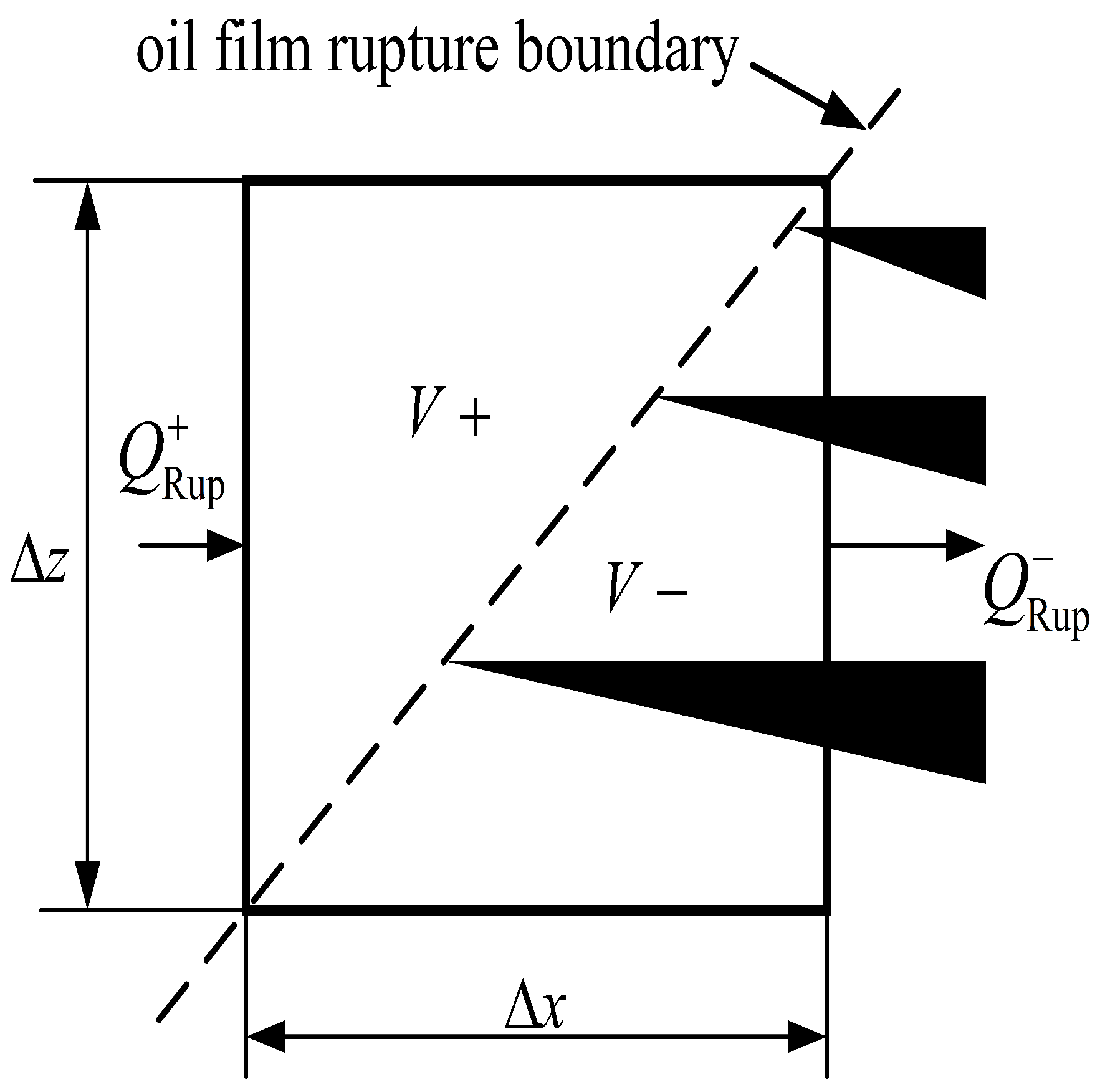
3.1. Boundary Conditions of Oil Film Rupture

In the steady state, the rupture boundary appears at the upstream boundary. As shown in Figure 3, at the oil film rupture boundary, the unit flow toward the cavitation region can be written as the sum of the shear term and the pressure term:
Q + R u p = U h 2 h 3 12 η p x
In the cavitation area, the pressure is still constant, and the fluid flows into a narrow area. The flow through the cavitation area is:
Q R u p = α U h 2
where 0 α 1 , α is the proportion of oil film. According to the conservation of mass,
Q + R u p = Q R u p
Therefore, we obtain:
1 α U h 2 h 3 12 η p x = 0
Since p x is only negative or zero, the boundary conditions of oil film rupture are α = 1 and p x = 0 , which are consistent with Reynolds boundary conditions.

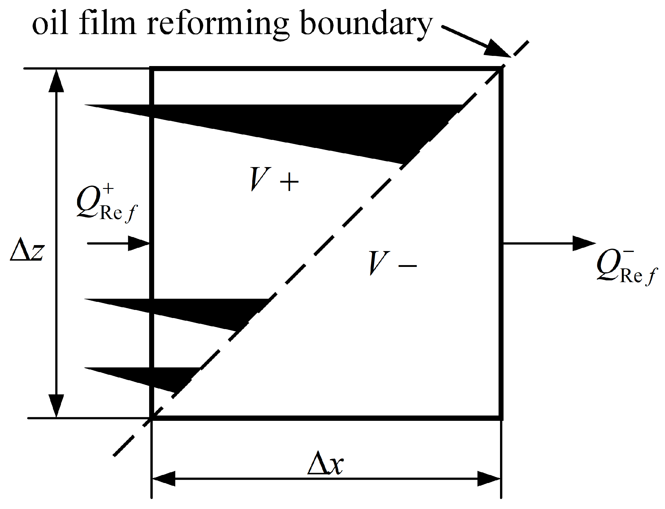
3.2. Boundary Conditions of Oil Film Reformation

As shown in Figure 4, at the boundary of oil film reformation, the unit flow from the cavitation area can be
Q + Re f = U h * 2 Δ z
where h * is the oil film thickness at the rupture area, and h * = α h . Downstream of the boundary condition, the unit flow is:
Q Re f = U h 2 h 3 12 η P x Δ z h 3 12 η P z Δ x
It can be seen from Q + Re f = Q Re f ,
U h * 2 Δ z = U h 2 Δ z h 3 12 η P x Δ z + P z Δ x
Because of lim Δ z 0 Δ x Δ z = d x d z , h * h = α , the oil film in the Equation (33) can be expressed as:
P x P z x z = 6 η U 1 α h 2

3.3. Control Equation of Cavitation Zone

For journal bearings with a moderately heavy load, there is strip flow in the cavitation area. This flow is mainly driven by shear, and the pressure in this region is basically unchanged, so the fluid equation in the cavity region is:
θ ρ c U h 2 = 0
where ρ c is the density of the fluid in the cavitation. In incompressible fluid, the relationship between density and pressure, namely bulk modulus, can be expressed as:
κ = ρ P ρ = ρ ρ c P ρ ρ ρ c ρ c
Let α = ρ ρ c . By introducing the switching function (g), we obtain:
g · κ = ρ ρ c P ρ ρ ρ c ρ c = α P α
when g = 1 , the area is in the full film lubrication state; when g = 0 , the area is in the cavitation area. Substituting
P = g κ ρ ρ = g κ α α
into Equation (13), the general equation of mixed lubrication of bearings considering cavitation effect is obtained:
θ ϕ x h 3 g κ α θ + R 2 z ϕ z h 3 g κ α z = 6 μ α U R ( h ¯ θ + σ ϕ s θ )

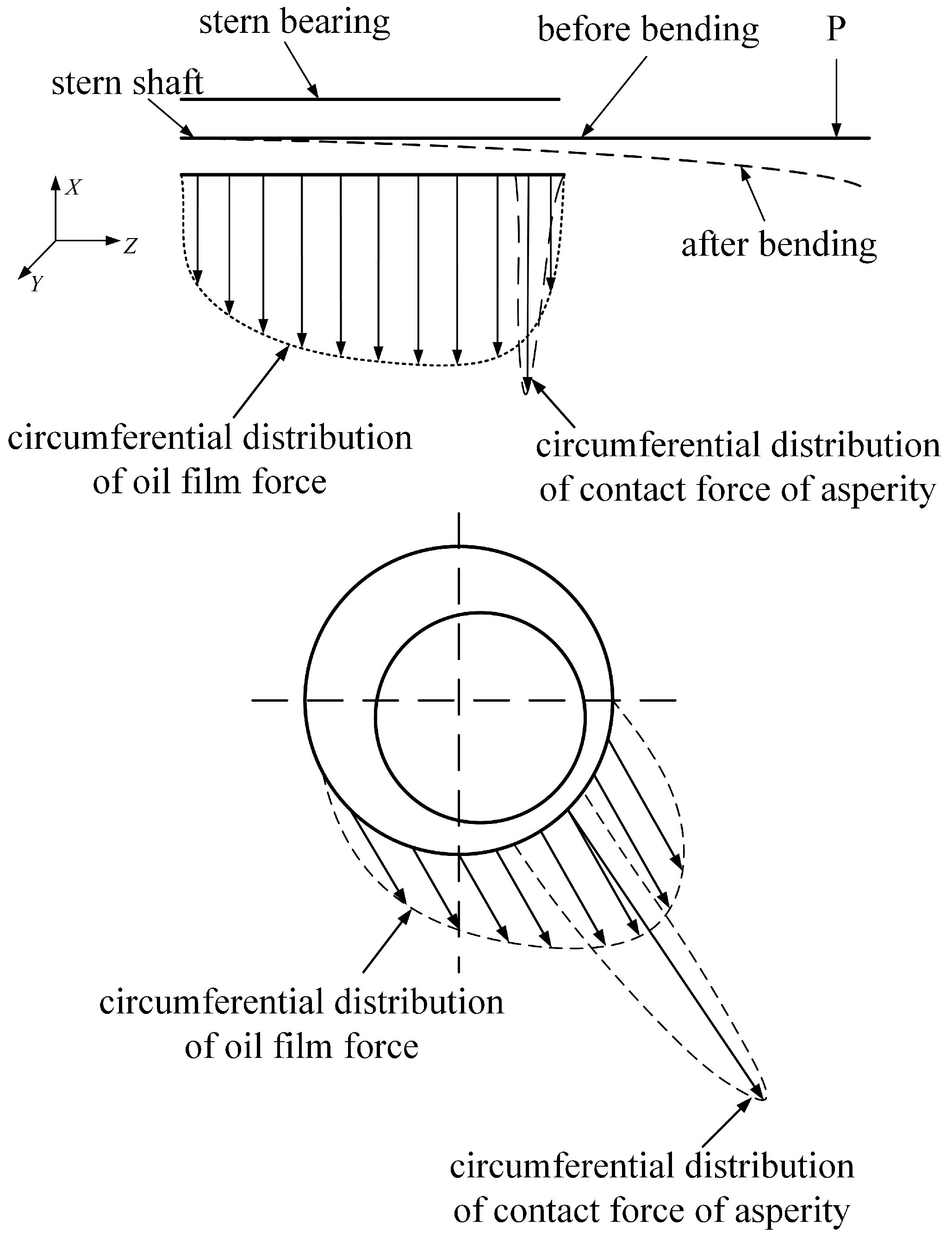
4. Oil Film Thickness Equation Considering Shaft Deflection

Due to the suspension of the ship stern shaft and the gravity of the propeller, the stern shaft is bent, which affects the pressure distribution of the bearing-lubricating oil film. The detailed expression of oil film thickness considering journal tilt can be analyzed, and the influence of stern shaft tilt caused by propeller-concentrated force on oil film thickness and the oil film pressure distribution of the stern bearing can be quantitatively calculated. However, because the oil film force and the asperity contact force act on the stern shaft at the same time, the stern shaft is also bent. In order to accurately consider the interaction between deflection and oil film force, asperity contact force, and external load, the displacement superposition method is used to calculate the shaft deflection.
As shown in Figure 5, the tail end of the shaft is bent by the gravity of the propeller. When the shaft rotates, due to the dynamic pressure lubrication, there is oil film distribution force at the bearing. If the ratio of oil film thickness to the comprehensive roughness of the lubricating surface is less than 4, the asperity also bears the load. In order to accurately solve the shaft deflection, the shaft is divided into n sections along the axial direction in the bearing support area. The z-direction coordinate of each point is Z i , and the displacement of each point is υ i x , υ i y . The oil film thickness corresponding to each section is h i θ ; then:
h i θ = c + e i cos θ ϕ
where
e i = υ i x + e i x 2 + υ i y + e i y 2
e i is the eccentricity of section i without considering shaft deformation; e i x and e i y are the components of eccentricity in the x and y directions, respectively, without considering shaft deformation respectively; ϕ is the offset angle; and θ is circumferential angle.
According to the above mathematical model, the bearing lubrication simulation program is written by FORTRAN. The program flow is shown in Figure 6:
(1)
The basic parameters of the bearing are input, such as bearing diameter, bearing radius clearance, bearing width, external load, lubricating oil viscosity, etc. The surface roughness of the bearing and the shaft and the pressure of the cavitation zone are input. The initial value of the eccentricity and the deviation angle are given, and the switching function (g) is set to 1;
(2)
The general Reynolds Equation (37) is solved to obtain the distribution of α and update the value of g. The finite difference method and the successive over-relaxation algorithm are applied for the calculation. The contact force of the asperity is solved. Then, the oil film force and the contact force of the asperity are substituted into the following formula to determine if the calculation is convergent:
F F o i l W A F ξ 1 , F o i l x + W x F o i l y + W y ξ 2
where ξ , i = 1 , 2 is the convergence precision in the calculation. A typical value for the convergence criteria is 0.003. If the above convergence condition is not satisfied, the eccentricity, offset angle, and oil film thickness are adjusted until the convergence condition is satisfied;
(3)
From Equation (8) to Equation (11), the friction force is solved, and finally, the friction coefficient is solved according to the following formula: μ j = F P .

5. Results and Analysis

The proposed algorithm for mixed bearing lubrication simulation is applied to show its effectiveness. The influence of cavitation and bearing deformation is investigated. The results are shown as follows.

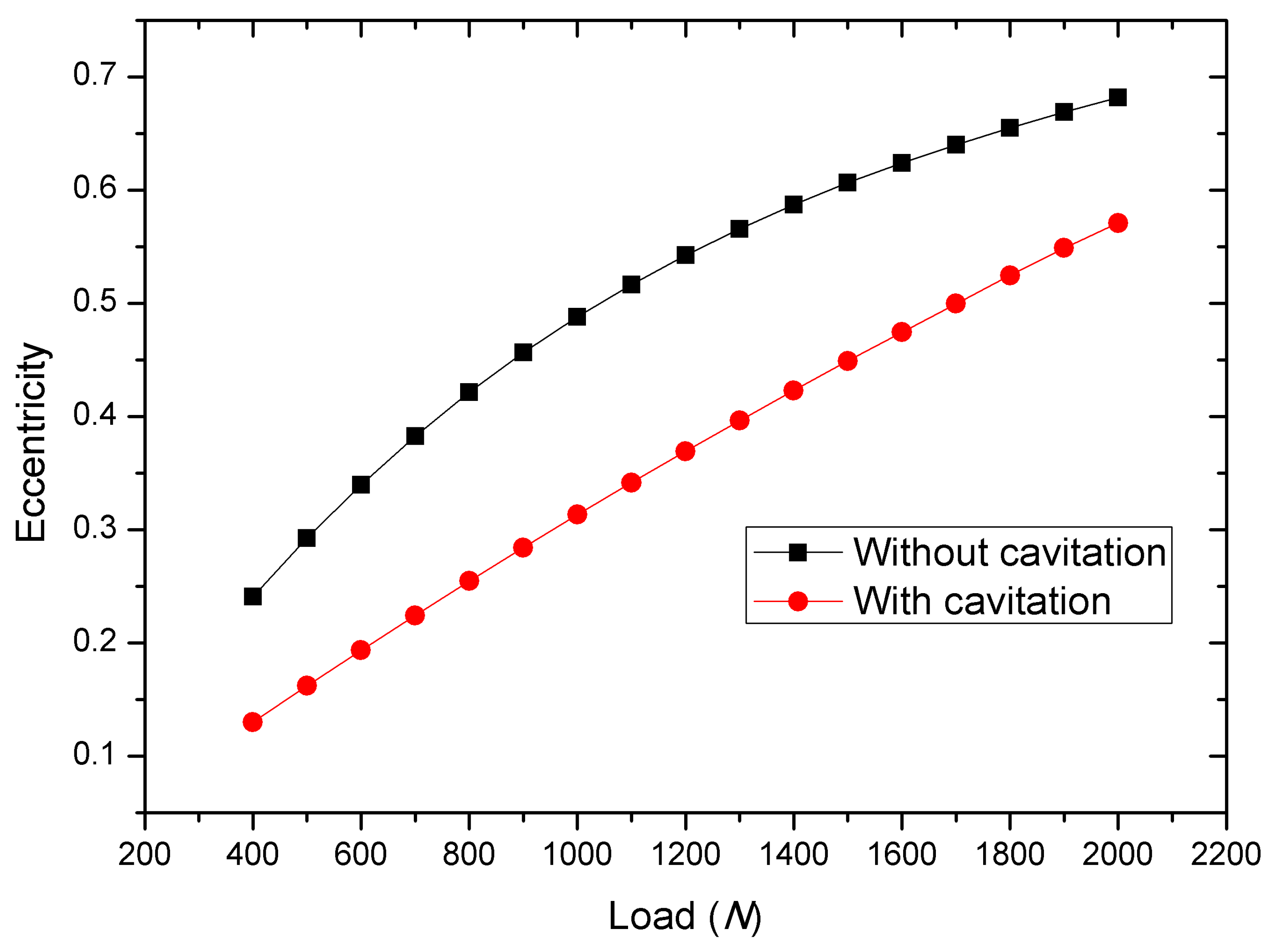
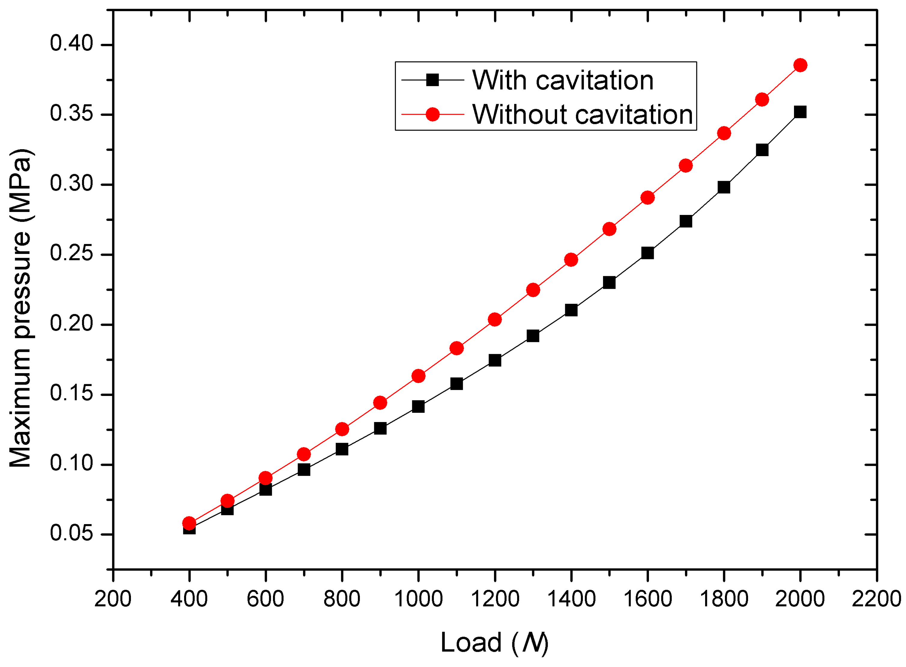
5.1. The Influence of Cavitation

In order to verify the accuracy of the calculation model and program, the parameters of sliding bearings in Refs. [37,38] are used. The bearing parameters are shown in Table 1.
Lioyd et al. demonstrated that the bearing capacity obtained by considering the influence of cavitation in the steady state can be three times higher than that without considering cavitation [39]. Dowson [40] also emphasized in the literature that cavitation can enhance the bearing capacity. The cavitation pressure in case 1 tested by Shen et al. is applied in the simulation [41]. The calculations using our proposed algorithm also support this conclusion. As shown in Figure 7, under the same load, the eccentricity of the bearing when considering the cavitation effect is lower than that without cavitation.
The distribution of bearing oil film pressure under different boundary conditions is calculated. As shown in Figure 8, the maximum film pressure is lower when the cavitation effect is considered. Under a 1.6 kN load, the maximum oil film pressure is 0.251 MPa when the cavitation effect is considered, while the maximum oil film pressure increases to 0.291 MPa when the cavitation effect is neglected. Due to the effect of cavitation, the eccentricity is reduced, and the maximum oil film pressure is reduced.
The effect of mesh size is also studied. In the simulation, four meshes with total elements count of 120, 480, 1920, and 7680 are applied. The calculated eccentricity of the bearing under a total load of 2000 N varies with the different meshes, with values of 0.57088 , 0.56524 , 0.56276 , and 0.56134 , respectively. The relative difference in eccentricity calculated with 120 elements compared to that with 7680 elements is 1.67 % . Based on this result, it can be concluded that the result approaches convergence in the calculation and that the mesh meets the requirements for the calculation.

5.2. The Mixed Lubrication State

The basic parameters of the bearing are presented in Table 2.
The lubrication state of the bearing under deflection is analyzed with the proposed model. The calculated results are shown in Table 3.
It can be seen from the table that the lubrication state gradually transits from mixed lubrication to liquid lubrication. The proportion of liquid film load increases rapidly, along with the increments of rotational speed. After considering the deflection deformation and surface roughness, the contact force can be accurately calculated.

6. Conclusions

Based on the cavitation algorithm of mass conservation, an asperity contact model is introduced in this paper, and a mixed lubrication model of bearing considering cavitation effect and stern shaft deflection is established. The lubrication performance of a sliding bearing is analyzed. By comparing the distribution of oil film pressure under different boundary conditions, it is found that cavitation can reduce eccentricity and maximum oil film pressure. The mixed lubrication model considering cavitation and shaft deformation proposed in this paper is able to provide accurate results of pressure distribution and coefficient of friction and can be applied in the design and analysis of journal bearings.

Author Contributions

Conceptualization, T.H., Y.L. and Y.X.; methodology, T.H. and Y.X.; software, T.H. and Y.X.; validation, Y.Z. and Y.X.; investigation, T.H., Y.Z., Y.L. and Y.X.; resources, T.H. and Y.X.; data curation, T.H.; writing—original draft preparation, T.H., Y.Z. and Y.X.; writing—review and editing, Y.X.; visualization, Y.Z. and Y.X.; supervision, T.H. and Y.X.; project administration, T.H. and Y.X.; funding acquisition, T.H. and Y.X. All authors have read and agreed to the published version of the manuscript.

Funding

This research was funded by the National Natural Science Foundation of China (No. 52241102, 12072065) and Fundamental Research Funds for the Central Universities of China (No. DUT22YG119).

Institutional Review Board Statement

Not applicable.

Informed Consent Statement

Not applicable.

Data Availability Statement

Data are available upon request due to restrictions.

Conflicts of Interest

The authors declare no conflict of interest.

References

  1. Wei, B.; Jiao, Y.; Wu, X. Numerical Calculation of Fluid Film Force on Journal Bearings Based on a Biconjugate Gradient-Stabilized Algorithm. J. Tribol. Trans. ASME 2022, 144, 114502. [Google Scholar] [CrossRef]
  2. Xie, Z.; Shen, N.; Zhu, W.; Tian, W.; Hao, L. Theoretical and experimental investigation on the influences of misalignment on the lubrication performances and lubrication regimes transition of water lubricated bearing. Mech. Syst. Signal Process. 2021, 149, 107211. [Google Scholar] [CrossRef]
  3. Xu, W.; Tian, Y.; Li, K.; Zhang, M.; Yang, J. Reynolds boundary condition realization in journal bearings: Location of oil film rupture boundary with layering-sliding mesh method. Tribol. Int. 2022, 165, 107330. [Google Scholar] [CrossRef]
  4. Jakobsson, B. The Finite Journal Bearing, Considering Vaporization. Trans. Chalmers Univ. Technol. 1957, 190, 117. [Google Scholar]
  5. Olsson, K.O. Cavitation in dynamically loaded bearings. In Akademiförlaget-Gumpert; Scandinavian University Books: Oslo, Norway, 1965. [Google Scholar]
  6. Hansen, E.; Kacan, A.; Frohnapfel, B.; Codrignani, A. An EHL Extension of the Unsteady FBNS Algorithm. Tribol. Lett. 2022, 70, 80. [Google Scholar] [CrossRef]
  7. Narwat, K.; Kumar, V.; Singh, S.J.; Kumar, A.; Sharma, S.C. Performance of rough surface hydrodynamic circular and multi-lobe journal bearings in turbulent regimes. Proc. Inst. Mech. Eng. Part J J. Eng. Tribol. 2023, 237, 860–880. [Google Scholar] [CrossRef]
  8. Huang, B.; Qiu, S.C.; Li, X.B.; Wu, Q.; Wang, G.Y. A review of transient flow structure and unsteady mechanism of cavitating flow. J. Hydrodyn. 2019, 31, 429–444. [Google Scholar] [CrossRef]
  9. Floberg, L. Sub-Cavity Pressures and Number of Oil Streamers in Cavitation Regions with Special Reference to the Infinite Journal Bearing; Royal Swedish Academy of Engineering Sciences: Stockholm, Sweden, 1968. [Google Scholar]
  10. Pan, C.H.T. Dynamic Analysis of Rupture in Thin Fluid Films. I—A Noninertial Theory. J. Lubr. Technol. 1983, 105, 96–104. [Google Scholar] [CrossRef]
  11. Brewe, D.E. Theoretical Modeling of the Vapor Cavitation in Dynamically Loaded Journal Bearings. J. Tribol. 1986, 108, 628–637. [Google Scholar] [CrossRef] [Green Version]
  12. Kumar, A.; Booker, J.F. A Mass and Energy Conserving Finite Element Lubrication Algorithm. J. Tribol. 1994, 116, 667–671. [Google Scholar] [CrossRef]
  13. Elrod, H.G. A Cavitation Algorithm. J. Lubr. Technol. 1981, 103, 350–354. [Google Scholar] [CrossRef]
  14. Vijayaraghavan, D.; Keith, T. Development and evaluation of a cavitation algorithm. Tribol. Trans. 1989, 32, 225–233. [Google Scholar] [CrossRef]
  15. Vincent, B.; Maspeyrot, P.; Frene, J. Cavitation in dynamically loaded journal bearings using mobility method. Wear 1996, 193, 155–162. [Google Scholar] [CrossRef]
  16. Tucker, P.G.; Keogh, P.S. A generalized computational fluid dynamics approach for journal bearing performance prediction. Proc. Inst. Mech. Eng. Part J J. Eng. Tribol. 1995, 209, 99–108. [Google Scholar] [CrossRef]
  17. Yan-Ming, C.; Mongis, J. Cavitation wear in plain bearing: Case study. Mec. Ind. 2005, 6, 195–201. [Google Scholar] [CrossRef]
  18. Flores, P.; Ambrósio, J.; Claro, J.C.P.; Lankarani, H.M.; Koshy, C.S. Lubricated revolute joints in rigid multibody systems. Nonlinear Dyn. 2009, 56, 277–295. [Google Scholar] [CrossRef] [Green Version]
  19. Song, Y.; Gu, C.w.; Ren, X. Development and validation of a gaseous cavitation model for hydrodynamic lubrication. PRoceedings Inst. Mech. Eng. Part-J. Eng. Tribol. 2015, 229, 1227–1238. [Google Scholar] [CrossRef]
  20. Shahmohamadi, H.; Rahmani, R.; Rahnejat, H.; Garner, C.P.; Dowson, D. Big End Bearing Losses with Thermal Cavitation Flow Under Cylinder Deactivation. Tribol. Lett. 2015, 57, 2. [Google Scholar] [CrossRef] [Green Version]
  21. Wang, L.; Zeng, Q.; Lu, C.; Liang, P. A numerical analysis and experimental investigation of three oil grooves sleeve bearing performance. Ind. Lubr. Tribol. 2019, 71, 181–187. [Google Scholar] [CrossRef]
  22. Jiang, S.; Ji, H.; Feng, D.; Li, Q.; Wu, S.; Chen, Z. Analysis and optimisation of grooved parallel slider bearings with cavitation. Meccanica 2020, 55, 1379–1391. [Google Scholar] [CrossRef]
  23. Zhang, C.; Cheng, H.S. Transient Non-Newtonian Thermohydrodynamic Mixed Lubrication of Dynamically Loaded Journal Bearings. J. Tribol. 1999, 122, 156–161. [Google Scholar] [CrossRef]
  24. Xu, W.; Zhao, S.; Xu, Y.; Li, K. Reynolds Model versus JFO Theory in Steadily Loaded Journal Bearings. Lubricants 2021, 9, 111. [Google Scholar] [CrossRef]
  25. Ding, A.; Ren, X.; Li, X.; Gu, C. A new gaseous cavitation model in a tilting-pad journal bearing. Sci. Prog. 2021, 104, 368504211029431. [Google Scholar] [CrossRef] [PubMed]
  26. Sobhi, S.; Nabhani, M.; Zarbane, K.; El Khlifi, M. Cavitation in oscillatory porous squeeze film: A numerical approach. Ind. Lubr. Tribol. 2022, 74, 636–644. [Google Scholar] [CrossRef]
  27. Sobhi, S.; El Khlifi, M.; Nabhani, M. Effects of both cavitation and non-Newtonian behavior on the performance of oscillatory anisotropic poroelastic squeeze film. Ind. Lubr. Tribol. 2023, 75, 145–156. [Google Scholar] [CrossRef]
  28. Tieu, A.K.; Freund, N.O. A high performance journal bearing with controlled elastic deflection. J. Tribol.-Trans. Asme 1995, 117, 702–708. [Google Scholar] [CrossRef]
  29. Liu, X.; He, T.; Yan, Y.; Meng, L.; Dong, J.; Guo, Y.; Zhou, P. Effects of axial offset and deflection on load-bearing characteristics of the permanent magnet bearing. Eng. Fail. Anal. 2023, 146, 107123. [Google Scholar] [CrossRef]
  30. He, T.; Zou, D.; Lu, X.; Guo, Y.; Wang, Z.; Li, W. Mixed-lubrication analysis of marine stern tube bearing considering bending deformation of stern shaft and cavitation. Tribol. Int. 2014, 73, 108–116. [Google Scholar] [CrossRef]
  31. Félix Quiñonez, A.; Morales-Espejel, G.E. Surface roughness effects in hydrodynamic bearings. Tribol. Int. 2016, 98, 212–219. [Google Scholar] [CrossRef]
  32. Mishra, P.C.; Rahnejat, H. Tribology of big-end bearings. In Tribology and Dynamics of Engine and Powertrain; Rahnejat, H., Ed.; Woodhead Publishing: Sawston, UK, 2010; pp. 635–659. [Google Scholar] [CrossRef]
  33. Allmaier, H.; Priestner, C.; Six, C.; Priebsch, H.H.; Forstner, C.; Novotny-Farkas, F. Predicting friction reliably and accurately in journal bearings—A systematic validation of simulation results with experimental measurements. Tribol. Int. 2011, 44, 1151–1160. [Google Scholar] [CrossRef]
  34. Greenwood, J.A.; Tripp, J.H. The Contact of Two Nominally Flat Rough Surfaces. Proc. Inst. Mech. Eng. 1970, 185, 625–633. [Google Scholar] [CrossRef]
  35. Patir, N.; Cheng, H.S. An Average Flow Model for Determining Effects of Three-Dimensional Roughness on Partial Hydrodynamic Lubrication. J. Lubr. Technol. 1978, 100, 12–17. [Google Scholar] [CrossRef]
  36. Wu, C.; Zheng, L. An Average Reynolds Equation for Partial Film Lubrication With a Contact Factor. J. Tribol. 1989, 111, 188–191. [Google Scholar] [CrossRef]
  37. Hong, S. Determining the Value of Pressure in the Cavitation Zone for Steady-state Journal Bearing. Mech. Eng. 2007, 5, 88–90. [Google Scholar]
  38. Feng, Z.; Ding, Q.; Cai, Y.; Sun, W. Experimental Investigation of the Dynamic Response of a Sliding Bearing System under Different Oil Pressure Levels. Appl. Sci. 2022, 12, 9759. [Google Scholar] [CrossRef]
  39. Lloyd, T.; Horsnell, R.; McCallion, H. Paper 8: An Investigation into the Performance of Dynamically Loaded Journal Bearings: Design Study. Proc. Inst. Mech. Eng. Conf. Proc. 1966, 181, 28–34. [Google Scholar]
  40. Dowson, D.; Taylor, C.M. Cavitation in Bearings. Annu. Rev. Fluid Mech. 1979, 11, 35–65. [Google Scholar] [CrossRef]
  41. Shen, C.; Khonsari, M.M. On the Magnitude of Cavitation Pressure of Steady-State Lubrication. Tribol. Lett. 2013, 51, 153–160. [Google Scholar] [CrossRef]
Figure 1. The force diagram on the bearing and the force balance condition.
Applsci 13 09033 g001
Figure 2. Thickness of lubricating oil film considering the surface roughness.
Applsci 13 09033 g002
Figure 3. Fluid element on oil film rupture boundary.
Applsci 13 09033 g003
Figure 4. Fluid element on the boundary of oil film reformation.
Applsci 13 09033 g004
Figure 5. The distribution of force acting on the bearing considering the shaft deflection.
Applsci 13 09033 g005
Figure 6. Program flow to calculate the bearing lubrication considering both cavitation and shaft deformation.
Applsci 13 09033 g006
Figure 7. Effects of cavitation on the eccentricity of journal bearing.
Applsci 13 09033 g007
Figure 8. Effects of cavitation on the maximum pressure in journal bearings.
Applsci 13 09033 g008
Table 1. Parameters of bearing for investigation of cavitation.
Radius (mm)Radius Clearance (mm)Length–Diameter RatioCavitation Pressure (kPa, Gage)
500.14551.333−72
Angular Velocity (rad/s)Dynamic Viscosity (Pa·s)Ambient Pressure (kPa, Gage)Density (kg/m 3 )
48.10.01270950
Table 2. Parameters of a ship stern bearing for investigation of deformation of bearings.
Inner radius of bearing (mm)100Outer radius of bearing (mm)160
Radius clearance (mm)0.3Width of Bearing(mm)240
Rotational speed (rpm)20–60Lubricating oil viscosity (Pa·s)0.082
Roughness of bushing ( 10 6 m)8Roughness of journal ( 10 6 m)2
Elastic modulus of bushing (GPa)100Elastic modulus of journal (GPa)210
Poisson ratio of bushing0.29Poisson ratio of journal0.3
Load of bearing (N)38,000Initial Bearing-journal contact friction coefficient0.1
Table 3. The contact load and film load of the bearing.
Speed (rpm)EccentricityFilm Load (N)Contact Load (N)Friction Force (N)Friction Coefficient
200.9536019,066.5018,943.961970.070.05183
300.9496026,172.5211,639.291261.440.03336
400.9448031,588.076231.27729.330.01928
500.9393035,510.862815.49388.550.01014
600.9317537,494.50831.29188.500.00492
Disclaimer/Publisher’s Note: The statements, opinions and data contained in all publications are solely those of the individual author(s) and contributor(s) and not of MDPI and/or the editor(s). MDPI and/or the editor(s) disclaim responsibility for any injury to people or property resulting from any ideas, methods, instructions or products referred to in the content.

