Article

Numerical Analysis of Cyclic Impact Damage Evolution of Rock Materials under Confining Pressure

1
School of Civil Engineering and Architecture, Anhui University of Science and Technology, Huainan 232001, China
2
State Key Laboratory of Mining Response and Disaster Prevention and Control in Deep Coal Mines, Anhui University of Science and Technology, Huainan 232001, China
3
Engineering Research Center of Underground Mine Construction, Ministry of Education, Anhui University of Science and Technology, Huainan 232001, China
*
Authors to whom correspondence should be addressed.
Appl. Sci. 2023, 13(15), 8822; https://doi.org/10.3390/app13158822
Submission received: 28 June 2023 / Revised: 24 July 2023 / Accepted: 28 July 2023 / Published: 31 July 2023
(This article belongs to the Special Issue Advances in Failure Behavior of Rocks)

Abstract

:
To study the effect of cyclic impacts and confining pressure on the damage evolution of rock materials, numerical simulations of cyclic impact tests on rock materials under confining pressure were carried out by LS-DYNA using dynamic relaxation and full restart analysis. The static confining pressure was applied by dynamic relaxation, and cyclic impacts were realized by full restart analysis. As the crack generation and propagation result in the failure of elements in the finite element model, the damage variable defined by the crack density method was characterized by volume reduction. Numerical simulation indicates that both the confining pressure and amplitude of incident stress waves significantly affect the damage evolution of rock materials. High incident stress waves lead to severe damage, while large confining pressure results in minor damage. Under confining pressure, the damage to rock materials is alleviated due to the constraint effect on crack propagation. The number of cyclic impacts before macroscopic fracture increases as the confining pressure increases and decreases when the amplitude of the incident stress waves increases. The cumulative damage of rock materials under confining pressure progressively increases with the number of cyclic impacts, and the damage evolution exhibits three distinct stages: rapid rising, steady development, and sharp rising.

1. Introduction

In recent years, due to the rapid economic development and increasing demand for mineral resources, rock engineering involved in tunneling, mining resources exploitation, and underground space utilization has extended into deep environments [1,2,3]. Moreover, during rock excavation in deep environments, the dynamic disturbance induced by blasting or rock burst has a significant influence on the stability of rock engineering [4,5,6]. In fact, the instability of surrounding rock in deep rock engineering is not typically attributed to a single impact event but cumulative damage induced by cyclic loads [7,8,9]. Cumulative damage induced by cyclic loads leads to crack generation and propagation, fracture, and eventually instability [10,11,12,13]. Therefore, investigating the dynamic damage evolution of rock materials under confining pressure holds significant engineering application value and is crucial for the protection of underground projects.
The damage evolution of rock materials under cyclic impact conditions has been investigated by analyzing elastic modulus, acoustic emission, energy dissipation, wave impedance, and other parameters. Lu [14] and Mei [15] identified three stages in the damage evolution of rocks under cyclic impact, namely the initial stage, low-speed stage, and accelerated stage. Rock specimens experience significant impact damage at the initial stage, then the cumulative damage gradually increases at the low-speed stage, and finally, the damage accelerates rapidly, resulting in rock failure. Based on the results of cyclic impact tests, Jin et al. [16,17] employed wave impedance to define the damage variable of rocks and revealed that the wave impedance method provides a more accurate depiction of the damage evolution characteristics of rocks than other commonly used methods for defining damage variables. Gan et al. [18] performed cyclic impact tests on sandstone using split Hopkinson pressure bar apparatus and analyzed the damage evolution based on the Weibull distribution statistical damage model. Liu et al. [19] conducted cyclic impact tests on sandstone specimens under various confining pressures and observed that the confining pressure restricts the accumulation of damage, namely a significant confining pressure effect. In the uniaxial cyclic impact test of rock, Wang et al. [20] employed the static crack initiation stress in a static stress-strain curve to estimate the dynamic crack initiation stress. By conducting constant amplitude cyclic impacts on granite, Tian et al. [21] found that the number of cyclic impacts initially increases and then decreases with the rise in axial pressure, which implies a strengthening effect when the pre-axial pressure is lower than the rock’s crack initiation stress. Under the combined action of pre-axial compression and cyclic impact, Tang et al. [22] observed that the stress-strain curve of rocks under various axial pressures exhibits two distinct features, namely rebound and non-rebound, and the fragmentation of rocks is intensified as the axial pressure rises.
Lv et al. [23] investigated the dynamic mechanical properties of rocks subjected to cyclic impacts under confining pressure and observed that the confining pressure can enhance the rock’s resistance to cyclic loading. Yu et al. [24] performed cyclic impact tests on rocks using a SHPB apparatus with a confining pressure device and discovered a power function relationship between rock damage variables and average strain rate. Through three-dimensional coupled static-cyclic impact tests, Jin et al. [25,26] found that axial pressure and confining pressure are negatively correlated and positively correlated with the total number of cyclic impacts, respectively. Therefore, reducing the axial pressure or increasing the confining pressure can improve the impact resistance of rock. By analyzing the energy dissipation and damage of rock under cyclic impact, Guo et al. [27] found that confining pressure can greatly increase the ability of basalt to resist external impact, and the cumulative specific energy absorption value at failure is 10 times higher than that without confining pressure.
Although numerous scholars have investigated the dynamic mechanical properties and damage characteristics of rocks under cyclic impacts, few scholars have utilized numerical simulations to analyze the cyclic impact damage evolution of rock under confining pressure. Therefore, numerical simulations of cyclic impact tests based on the SHPB apparatus were carried out for rock under confining pressure by LS-DYNA. Then the damage evolution was investigated by the volume change of the rock specimen after cyclic impacts, and the damage evolution model was established using crack density as the damage variable. The objective of this study is to provide a new method for analyzing the cyclic impact damage evolution of rock materials under confining pressure.

2. Numerical Modeling and Verification

2.1. SHPB Fundamentals

SHPB (split Hopkinson pressure bar) apparatus is a widely employed equipment to investigate the dynamic mechanical properties of rock materials. A SHPB apparatus comprises an impact bar, an incident bar, a transmission bar, and an energy absorption device. During a SHPB test, the rock specimen is sandwiched between the incident bar and transmission bar. Axial pressure and confining pressure loading systems are incorporated with the SHPB apparatus to achieve combined dynamic and static loading.
By collecting incident wave εi(t) and reflected wave εr(t) on the incident bar and transmitted wave εt(t) on the transmission bar, the stress-strain relationship of the rock specimen can be determined according to the classical two-wave method.
ε t = c 0 l 0 0 t [ ε i t ε r t ε t t ] d t = 2 c 0 l 0 0 t ε r t d t
σ t = E ε t t
where E and c0 are the elastic modulus and wave velocity of steel pressure bars, respectively, and l0 is the length of the rock specimen.
During cyclic impact tests, a half-sine incident stress wave can effectively maintain a constant loading strain rate and ensure stress uniformity within the specimen during deformation [28,29]. In numerical simulations, the half-sine incident stress wave can be achieved by using initial velocity through a spindle-type impact bar or applying half-sine stress waves at the front end of the incident bar [30]. In this study, the half-sine incident wave is directly applied at the front end of the incident bar. The fitting formula of the half-sine incident stress wave is shown in Equation (3).
P d t = P m a x 1 2 1 2 cos ( 2 π ω t ) t 1 / ω 0 t > 1 / ω
where Pmax, ω and t are amplitude, angular frequency, and duration of the half-sine incident stress wave, respectively.
In this study, considering the physical and mechanical properties of rock, the amplitude of half-sine incident stress wave is taken as 170 MPa, 180 MPa, and 190 MPa.

2.2. Numerical Modeling

Based on the actual size of a SHPB apparatus with a diameter of 50 mm, the finite element model of the incident bar, transmission bar, and rock specimen is established using the solid element in Hypermesh software. In the numerical model, both the incident bar and transmission bar have a diameter of 50 mm and a length of 2 m, and the rock specimen has a diameter of 50 mm and a length of 25 mm. To accurately represent the damaging effect and damage evolution of rock under cyclic impacts, the rock specimen is meshed into 20 grids along the axial direction and 30 grids along the radial direction, as shown in Figure 1.
During the cyclic impact test, both the incident bar and transmission bar are in a linear elastic state. Therefore, the isotropic linear elastic model, namely MAT_ELASTIC, is applied for both the incident bar and transmission bar. Considering the damage evolution induced by cyclic impacts, a dynamic damage constitutive model accounting for strain rate effects, namely Holmquist–Johnson–Cook (HJC) model, is applied to rock material [31,32]. The HJC model can effectively simulate the dynamic response of rock-like materials under high strain rates, large deformation, and high confining pressure [33]. Table 1 and Table 2 give the basic physical and mechanical parameters of the steel pressure bar and rock material. In Table 1 and Table 2, ρ is density, μ is Poisson’s ratio, E is elastic modulus, fc is static uniaxial compressive strength, G is shear modulus, and K is bulk modulus.
Keyword MAT_ADD_EROSION defines the failure threshold and controls the damage incurred by the material, and the maximum failure principal strain is set as 0.006. To make stress wave propagation closer to reality, the contact between the steel pressure bar and the rock specimen is set as an erosion contact, namely CONTACT_ERODING_SURFACE_TO_SURFACE, with the rock face being dominant. The remaining parameters in both contact types are set as the default values.

2.3. Cyclic Impact Simulation of Rock Materials under Confining Pressure

As illustrated in Figure 2, cyclic impact tests for rock material under confining pressure are implemented by applying static circumferential confining pressure on rock specimens before impact load. In Figure 2, Pc and Pd represent the static circumferential confining pressure and dynamic impact load.
LS-DYNA offers two methods to apply static circumferential confining pressure on rock specimens before cyclic impact, namely the dyain file method and the dynamic relaxation method [34]. But the dyain file method cannot inherit the damage of rock specimens in cyclic impact simulations. Therefore, the dynamic relaxation method is employed for a full restart analysis to apply static circumferential confining pressure on rock specimens. The convergence of dynamic relaxation can be assessed through the deformation movement energy. When the dynamic relaxation process ends, the prestressed state is transferred to the initial conditions for transient analysis, allowing for a full restart. The key steps of cyclic impact simulation of rock materials under confining pressure are listed as follows.
(1)
Segment setting. The lateral surface of the cylindrical rock specimen and the end surface of the transmission bar are defined as different groups by using the keyword SEGMENT_SET.
(2)
Boundary setting. Firstly, constrain all translation and rotation of the incident bar and transmission bar except the horizontal motion by using the keyword SPC_SET. Secondly, set the non-reflective boundary at the end surface of the transmission bar by using the keyword NON_REFLECTING.
(3)
Confining pressure applying. Firstly, define a preload curve according to static circumferential confining pressure by using the keyword DEFINE_CURVE. Secondly, apply the preload curve on the lateral surface of the cylindrical rock specimen by using the keyword LODING_ SEGMENT_SET. Thirdly, run the dynamic relaxation analysis by keyword CONTROL_DYNAMIC_RELAXATION to make the static circumferential confining pressure maintain the designed value before impact load.
(4)
Cyclic impacts realization. Cyclic impact simulation is realized by using a full restart analysis.
Cyclic impact simulations are conducted on rock specimens under confining pressures of 0 MPa, 2 MPa, and 4 MPa, respectively. The amplitude of half-sine incident stress for cyclic impact simulations is 170 MPa, 180 MPa, and 190 MPa under 0 MPa confining pressure, while it is only 180 MPa under 2 MPa and 4 MPa confining pressure. The objective is to investigate the effect of the amplitude of incident stress waves and confining pressure on the damage degree and damage evolution of rock materials.

2.4. Verification of Numerical Model

SHPB apparatus relies on two basic assumptions, namely, one-dimensional stress wave assumption and stress uniformity assumption. It is crucial to achieve stress uniformity in rock specimens to ensure the validity of numerical simulation. To satisfy the stress uniformity assumption, the dynamic stresses at both ends of the rock specimen must be approximately equal [35,36]. Therefore, stress uniformity can be verified by comparing the stress-time histories at both ends of rock specimens during cyclic impacts. As illustrated in Figure 3 and Figure 4, stress balance verifications are conducted using the initial impact in different conditions. In Figure 3 and Figure 4, In, Re, and Tr represent incident stress waves, reflected stress waves, and transmitted stress waves, respectively. It can be observed that the sum of the incident stress wave and reflected stress wave aligns with the transmitted stress wave prior to reaching the peak stress, indicating the achievement of stress balance during the impact.

3. Results and Analysis

3.1. Dynamic Stress-Strain Curve Analysis

When the amplitude of half-sine incident stress waves is 180 MPa, the dynamic stress-strain curves of rock specimens after cyclic impacts under different confining pressures are presented in Figure 5. In Figure 5, n represents the number of cyclic impacts.
As shown in Figure 5, dynamic stress-strain curves exhibit a relatively similar trend, which can be roughly divided into two stages, namely the initial nearly straight loading stage and the nonlinear unloading stage with a gradually decreasing slope. When rock specimens remain integrity, the partial rebound at the end of the unloading stage indicates the release of stored elastic energy.
When the confining pressure is constant, with the number of cyclic impacts increasing, both the slope in the straight loading stage, namely elastic modulus, and peak stress of the dynamic stress-strain curve gradually decreases. Under cyclic impacts, internal crack initiation and propagation after each impact load lead to the decrease of mechanical properties of rock specimens. Consequently, the cumulative crack development of cyclic impacts intensifies the damage to the internal structure of the rock. The larger the number of cyclic impacts, the greater the damage, leading to a significant reduction in mechanical properties. With the increase of confining pressure, the number of cyclic impacts increases, which implies that the confining pressure can slow down the crack propagation and reduce damage accumulation.

3.2. Numerical Simulation of Rock Fracture

When the amplitude of half-sine incident stress waves is 180 MPa, the rock fracture process after cyclic impacts under 0 MPa confining pressure and 2 MPa confining pressure are illustrated in Figure 6 and Figure 7, respectively. In numerical simulation, the crack generation and propagation result in the failure of elements.
As shown in Figure 6, the rock failure process exhibits a fracture surface approximately along the axial direction without the end effect. At the initial stage of the fracture process, a crack first appears on the periphery of the rock specimen, as shown in Figure 6b. Under the impact loads, the rock specimen experiences axial compression and radial tension. When the transverse tensile strain exceeds the criterion, short cracks generate in the middle of the outer side of the rock specimen, as depicted in Figure 6c. As the transverse tension deformation continues, the short cracks extend parallel to the length of the rock specimen until penetrating the entire specimen. Eventually, strip-shaped blocks are observed at the periphery of the rock specimen, as depicted in Figure 6d. Under cyclic impacts, the fracture of the rock specimen extends from the periphery toward the interior.
As illustrated in Figure 7, the fracture on the rock specimen increases with the number of cyclic impacts. In the early stage of the fracture process, a crack also first generates on the periphery of the rock specimen, as shown in Figure 7b. Due to the constraint effect of confining pressure on crack propagation, the number of cyclic impacts before macroscopic fracture in Figure 7 is much larger than that in Figure 6, and the number of cracks in Figure 7b is much less than that in Figure 6b. The damage to the rock specimen accumulates with the crack propagation after each impact. With the number of cyclic impacts increasing, the cracks extend from the periphery towards the interior, as illustrated in Figure 7c–g. Finally, strip-shaped blocks are also observed at the periphery of the rock specimen, as depicted in Figure 7h.

3.3. Defining Damage Variable

Damage variables can be defined in various ways, such as elastic modulus, wave velocity, energy dissipation, and crack density. In the historical progression of damage definitions, crack density is one of the earliest methods to characterize damage variables. However, the practical measurement of crack density poses significant challenges. In numerical simulation, the crack generation and propagation result in the failure of elements. As failed elements are deleted in the finite element model, the volume reduction induced by element failure provides insight into the propagation of cracks. The volume of rock specimen after each impact can be recorded in numerical simulations with relatively low computational cost; then, the crack density method is employed to characterize the damage variable. As the crack density can be characterized by volume reduction after each impact in numerical simulation, the damage variable can be expressed as:
D = 1 V i V
where D is the damage variable, and Vi and V are the volume of rock specimens after ith impact and before impact, respectively.
The volume of rock specimens can be derived from the volume–time history curve obtained by the post-processing software LS-PREPOST. The volume of the cylindrical rock specimen before impact is 49.035 × 10⁻⁶ m3. The smaller the volume of the rock specimen after impact, the greater the damage to the rock specimen.

3.4. Damage Evolution Analysis

Rock is a typical brittle material in nature, characterized by numerous microcracks in it. When subjected to an external load or energy, rock experiences closure of original fissures, initiation and propagation of new cracks, and eventual coalescence of these cracks. This process significantly impacts the macroscopic behavior of rock. By incorporating the volume of the rock specimen after cyclic impacts into Equation (4), the damage of the rock specimen under various impact conditions is obtained. The calculated results are presented in Table 3, and the trends of damage evolution are depicted in Figure 8.
As illustrated in Figure 8, the cumulative damage of the rock specimen under confining pressure progressively increases with the number of cyclic impacts, exhibiting three distinct evolutionary stages: rapid rising, steady development, and sharp rising. In the numerical simulation, as there are no pre-existing cracks in the rock specimen, the initial impact generates the cracks in the rock specimen, and the subsequent impacts lead to the propagation of the previously generated cracks. As the constraint effect of confining pressure, damage accumulates at a low speed after each impact. Once the damage reaches a specific level, the damage accelerates to form a macroscopic fracture due to the rapid propagation of cracks.
Both confining pressure and amplitude of incident stress waves significantly affect the damage evolution and the number of cyclic impacts. As seen from Figure 8a, under 0 MPa confining pressure, the damage of the rock specimen at 190 MPa incident stress wave is more severe than that at 170 MPa. The high incident stress wave leads to many cracks generated after the first impact and a small number of cyclic impacts. The higher the amplitude of the incident stress wave, the greater the damage after each impact and the smaller the number of cyclic impacts before macroscopic fracture. As seen from Figure 8b, under the same number of cyclic impacts, the damage of the rock specimen under 4 MPa confining pressure is significantly less than that under 0 MPa confining pressure. Due to the existence of confining pressure, the development of transverse cracks in the rock specimen is constrained; namely, the confining pressure has a significant constraint effect on the propagation of cracks in the rock specimen. To a certain extent, the constraint effect offsets the generated transverse tension and reduces the axial tensile cracks. Also, the constraint effect increases with the increase of confining pressure. The larger the confining pressure, the less the damage, and the bigger the number of cyclic impacts.

4. Discussion

Numerical simulation provides an efficient, flexible, and economical means to simulate the dynamic response of rock under complex impact loads. In this study, the numerical simulation of cyclic impact tests on rock materials under confining pressure was successfully realized through LS-DYNA by first applying static circumferential confining pressure before impact load with dynamic relaxation, then conducting cyclic impact tests with full restart analysis. Subsequently, the cyclic impact damage evolution of rock materials under confining pressure was analyzed based on simulation results. As only the HJC model is employed for rock materials in numerical simulation, the applicability of this study may be limited. Follow-up studies may consider more constitutive models for comparative studies to improve the applicability of simulation results. Moreover, the parameters of the constitutive model may also vary to represent various kinds of rocks.
Based on numerical simulation, both confining pressure and amplitude of half-sine incident stress waves show a significant effect on the damage evolution of rock materials. As the dynamic response of rock material under an impact load is closely related to the waveform of impact load, follow-up studies may consider various waveforms of incident stress waves, such as rectangular stress waves, trapezoidal stress waves, and triangular stress waves. The damage variable is characterized by volume change induced by failure elements in the finite element model. Therefore, the grid of the rock specimen has an influence on the accuracy of calculated damage. However, small element size consumes much time for numerical simulation. Therefore, follow-up studies may use the discrete element method, such as DEM and PFC, to investigate crack generation and propagation during cyclic impacts under confining pressure.

5. Conclusions

Numerical simulation of cyclic impact tests on rock materials under confining pressure has been carried out by LS-DYNA using dynamic relaxation and full restart analysis. This analyzes the cyclic impact damage evolution of rock materials under confining pressure by defining damage variables with the crack density method. The conclusions are drawn as follows.
(1)
Cyclic impact tests of rock materials under confining pressure can be simulated first by applying static confining pressure with a dynamic relaxation process, then conducting cyclic impact tests with full restart analysis.
(2)
In numerical simulation, the crack generation and propagation result in the failure of elements in the finite element model. Thus, the damage variable defined by the crack density method can be characterized by volume reduction.
(3)
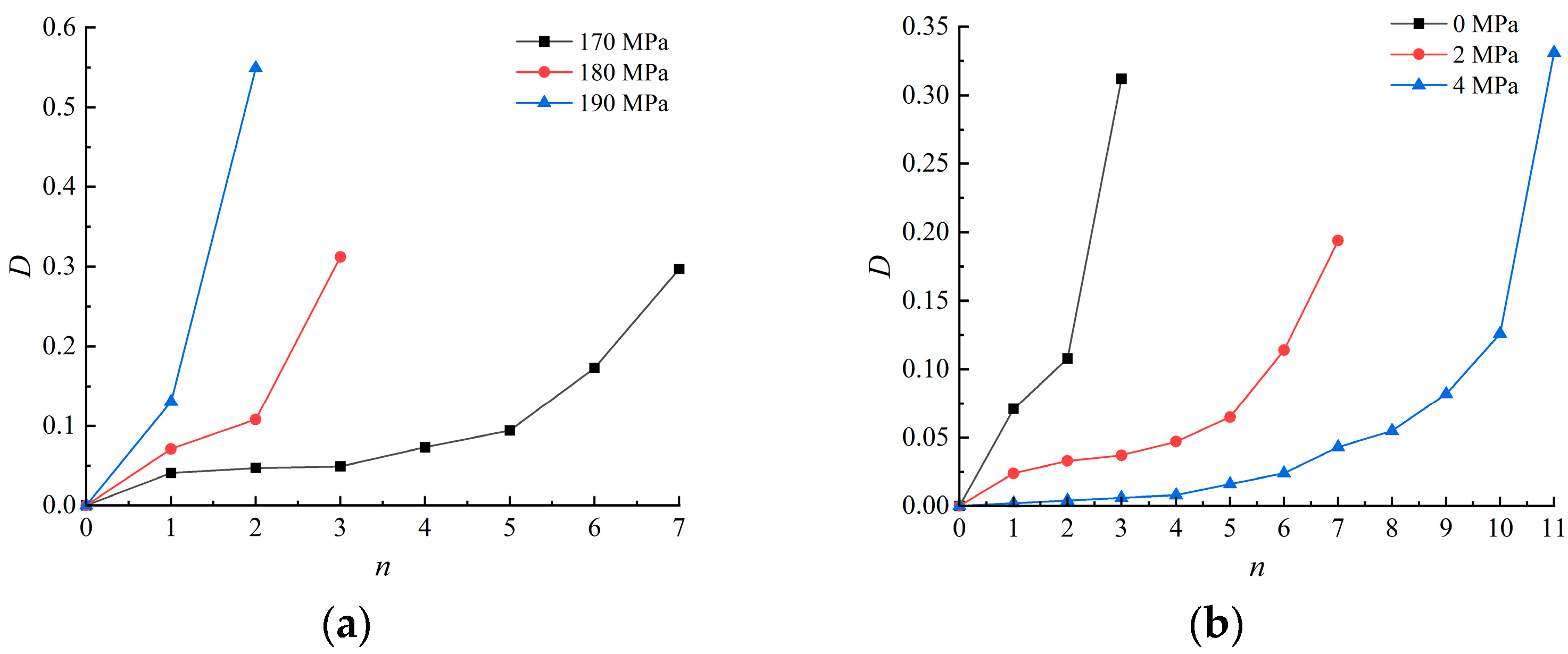
The number of cyclic impacts before macroscopic fracture increases with the increase of confining pressure and decreases with the increase of the amplitude of the incident stress wave.
(4)
The cumulative damage of rock under confining pressure progressively increases with the number of cyclic impacts, and damage evolution exhibits three distinct stages: rapid rising, steady development, and sharp rising. A high incident stress wave leads to serve damage after the first impact and a small number of cyclic impacts.
(5)
Under confining pressure, the damage of rock is alleviated due to the constraint effect on crack propagation. Large confining pressure results in minor damage and a large number of cyclic impacts.

Author Contributions

Conceptualization, P.Y.; Software, A.L.; Validation, Q.Z.; Formal analysis, P.Y.; Data curation, A.L.; Writing—original draft, A.L.; Writing—review & editing, P.Y. All authors have read and agreed to the published version of the manuscript.

Funding

This work was funded by Anhui Provincial Natural Science Foundation (No. 2108085ME156 and No. 1808085QE148), The University Synergy Innovation Program of Anhui Province (No. GXXT-2022-020), China Postdoctoral Science Foundation (No. 2018M642504), and Natural Science Research Project of Colleges and Universities in Anhui Province (No. KJ2017A097).

Data Availability Statement

The data used to support the findings of this study are available from the corresponding author upon request.

Conflicts of Interest

The authors declare no conflict of interest.

References

  1. Qian, Q.H. Challenges faced by underground projects construction safety and countermeasures. J. Rock Mech. Eng. 2012, 31, 1945–1956. [Google Scholar]
  2. Dai, B.; Shan, Q.W.; Chen, Y.; Luo, X.Y. Mechanical and energy dissipation characteristics of granite under cyclic impact loading. J. Cent. South Univ. 2022, 29, 116–128. [Google Scholar] [CrossRef]
  3. Xie, H.P. Research framework and anticipated results of deep rock mechanics and mining theory. Adv. Eng. Sci. 2017, 49, 1–16. [Google Scholar] [CrossRef]
  4. Huang, Y.H.; Wen, L.; Ma, J.J.; Kou, Z.L. Mechanical properties and damage evolution characteristics of sandstone under cyclic impact with axial compression. Min. Metall. Eng. 2021, 41, 6–10. [Google Scholar]
  5. Yang, G.L.; Yang, R.S.; Che, Y.L. Damage accumulative effect of enclosing rock under periodic blasting vibration. J. China Coal Soc. 2013, 38, 25–29. [Google Scholar]
  6. Li, H.B.; Xia, X.; Li, J.; Zhao, J.; Liu, B.; Li, Y.Q. Rock damage control in bedrock blasting excavation for a nuclear power plant. Int. J. Rock Mech. Min. Sci. 2011, 48, 210–218. [Google Scholar] [CrossRef]
  7. Liu, M.G.; Zhang, G.H.; Liu, S.B.; Li, Q. Research on accumulative damage effect of interlaid rock in damaoshan tunnel group with small clear distance. J. Rock Mech. Eng. 2009, 28, 1363–1369. [Google Scholar]
  8. Liu, W.; Zeng, P.; Yan, L.; Yang, Y.; Liu, L.S. Mechanical properties and permeability evolution of weakly weathered rocks under cyclic impact. J. China Coal Soc. 2021, 46, 1855–1863. [Google Scholar] [CrossRef]
  9. Fan, L.D.; Xu, F.; Yu, Y.Q.; Zhang, Z.W.; Yu, L.W.; Zhou, G.J. Experimental study of dynamic mechanical characteristics of sandstone under one-dimensional coupled static-cyclic impact loads. Chin. J. High Press. Phys. 2022, 36, 48–59. [Google Scholar]
  10. Deng, H.W.; Liu, C.J.; Ke, B.; Wang, Y.; Zhang, Y.N. Experimental study on microdamage characteristics of granite under cyclic dynamic disturbance. J. Eng. Sci. 2017, 39, 1634–1639. [Google Scholar] [CrossRef]
  11. Hao, H.; Wu, C.; Zhou, Y. Numerical analysis of blast-induced stress waves in a rock mass with anisotropic continuum damage models Part 1: Equivalent material property approach. Rock Mech. Rock Eng. 2002, 35, 79–94. [Google Scholar] [CrossRef]
  12. Shariati, M.; Tahir, M.M.; Wee, T.C.; Shah, S.N.R.; Jalali, A.; Abdullahi, M.M.; Khorami, M. Experimental investigations on monotonic and cyclic behavior of steel pallet rack connections. Eng. Fail. Anal. 2018, 85, 149–166. [Google Scholar] [CrossRef]
  13. Jalali, A.; Toghroli, A.; Shariati, M.; Ibrahim, Z. Assessment of stiffened angle shear connector under monotonic and fully reversed cyclic loading. In Proceedings of the Fifth International Conference on Advances in Civil, Structural, and Mechanical Engineering-CSM 2017, Zürich, Switzerland, 2–3 September 2017; pp. 64–68. [Google Scholar]
  14. Lu, H. Responses on Dynamic Responses and Damage Effect of Red Sandstone with Fluid-Solid Coupling under Impact Loading. Ph.D. Thesis, China University of Mining and Technology, Beijing, China, 2013. [Google Scholar]
  15. Mei, N.F. Research on Fatigue Damage and Mechanical Characteristics of Brittle Rock under Cycle Dynamic Loading. Master’s Thesis, China University of Geosciences, Wuhan, China, 2014. [Google Scholar]
  16. Jin, J.F.; Li, X.B.; Yin, Z.Q.; Zou, Y. A method for defining rock damage variable by wave impedance under cyclic impact loadings. Rock Soil Mech. 2011, 32, 1385–1393+1410. [Google Scholar] [CrossRef]
  17. Jin, J.F.; Zhong, H.B.; Wu, Y.; Guo, Z.Q.; Zhou, X.J. Method selection for defining damage variable of rock subjected to static loadings and cyclic impacts. Nonferrous Met. Sci. Eng. 2013, 4, 85–90. [Google Scholar] [CrossRef]
  18. Gan, D.Q.; Tian, X.X.; Liu, Z.Y.; Gao, F. Study on mechanical and damage characteristics of sandstone under cyclic impact state. China Min. Mag. 2021, 30, 203–211. [Google Scholar]
  19. Liu, S.H.; Xu, J.Y.; Wang, P.; Zhang, G.X. Mechanical and ultrasonic analysis on damage of sandstone under cyclical impact loading with confining pressure. J. Vib. Shock 2015, 34, 190–194. [Google Scholar] [CrossRef]
  20. Wang, Z.L.; Yang, H.; Tian, N.C. Mechanical property and damage evolution mechanism of granite under uniaxial cyclic impac. J. Eng. Geol. 2014, 22, 79–86. [Google Scholar]
  21. Tian, N.C.; Wang, Z.L.; Xiong, F.; Liu, Z.Y. Influence of axial pressure on dynamic mechanical properties of granite under cyclic impact loading. J. Harbin Inst. Technol. 2021, 53, 156–164. [Google Scholar]
  22. Tang, L.Z.; Wang, C.; Cheng, L.P.; Gao, L.H. Experimental study of mechanical characteristics of skarn under one-dimensional coupled static and cyclic impact loads. J. Cent. South Univ. Sci. Technol. 2015, 46, 3898–3906. [Google Scholar]
  23. Lv, X.C.; Xu, J.Y.; Zhao, D.H.; Ge, H.H.; Wang, Z.D. Research on confining pressure effect of sandstone dynamic mechanical performance under the cyclical impact loadings. Eng. Mech. 2011, 28, 138–144. [Google Scholar]
  24. Yu, Y.; Xu, Q.; Diao, X.H.; Yan, Z.Y. I Effect of cyclic impact on sandstone characteristics under confining pressures. J. Huazhong Univ. Sci. Technol. Nat. Sci. Ed. 2019, 47, 127–132. [Google Scholar] [CrossRef]
  25. Jin, J.F.; Li, X.B.; Zhong, H.B. Study of dynamic mechanical characteristic of sandstone subjected to three-dimensional coupled static-cyclic impact loadings. Chin. J. Rock Mech. Eng. 2013, 32, 1358–1372. [Google Scholar]
  26. Jin, J.F.; Li, X.B.; Chang, J.R.; Tao, W.; Qiu, C. Stress strain curve and stress wave characteristics of rock subjected to cyclic impact loadings. Explos. Shock Waves 2013, 33, 613–619. [Google Scholar]
  27. Guo, L.J.; Ma, H.Y.; Xu, J.L.; Wang, X.S.; Deng, Q.C.; Li, P.F. Study on energy dissipation characteristics and damage of rock under cyclic impact. Min. Res. Dev. 2023, 43, 106–112. [Google Scholar] [CrossRef]
  28. Zhou, Z.L.; Li, X.B.; Zhao, G.Y.; Hu, L.Q. Three dimensional numerical analysis of perfect loading wave-form of rock with SHPB. Min. Metall. Eng. 2005, 3, 18–20. [Google Scholar]
  29. Zhou, Z.L.; Li, X.; Liu, A.; Zou, Y. Stress uniformity of split Hopkinson pressure bar under half-sine wave loads. Int. J. Rock Mech. Min. Sci. 2011, 48, 697–701. [Google Scholar] [CrossRef]
  30. Huang, Y.H.; Liang, S.F.; Liu, D.S.; Xiong, W.G.; Xu, R. 3D SHPB device experimental design and principle research. J. Beijing Inst. Technol. 2014, 34, 1024–1027+1033. [Google Scholar] [CrossRef]
  31. Yuan, P.; Ma, Q.Y. Correction of non-parallel end-faces of rock specimens in SHPB test. Explos. Shock Waves 2017, 37, 929–936. [Google Scholar] [CrossRef]
  32. Wang, X.Y.; Li, Q.; Wang, W.; Zhang, M.T.; Wang, Q.Z. Numerical simulation of damage evolution of sandstone under combined dynamic and static loading. Sci. Technol. Eng. 2022, 22, 6248–6254. [Google Scholar]
  33. Ling, T.L.; Wu, S.F.; Liu, D.S.; Liang, S.F.; Li, C.; Ma, J.H. Determination of Holmquist-Johnson-Cook model parameters for sandstone. J. China Coal Soc. 2018, 43, 2211–2216. [Google Scholar] [CrossRef]
  34. Yang, J.; Liu, K.; Li, X.; Liu, Z. Stress initialization methods for dynamic numerical simulation of rock mass with high in-situ stress. J. Cent. South Univ. 2020, 27, 3149–3162. [Google Scholar] [CrossRef]
  35. Dai, F.; Huang, S.; Xia, K.; Tan, Z. Some fundamental issues in dynamic compression and tension tests of rocks using split Hopkinson pressure bar. Rock Mech. Rock Eng. 2010, 43, 657–666. [Google Scholar] [CrossRef]
  36. Gong, F.Q.; Li, X.B.; Liu, X.L. Tests for sandstone mechanical properties and failure model under triaxial SHPB loading. J. Vib. Shock 2012, 31, 29–32. [Google Scholar] [CrossRef]
Figure 1. Grid diagram of the incident bar, transmission bar, and rock specimen.
Applsci 13 08822 g001
Figure 2. Force diagram of rock specimen under combined confining pressure and impact load. (a) Combined confining pressure and impact load, (b) Static circumferential confining pressure.
Applsci 13 08822 g002
Figure 3. Stress balance under 0 MPa confining pressure. (a) 170 MPa half-sine incident stress wave, (b) 180 MPa half-sine incident stress wave, (c) 190 MPa half-sine incident stress wave.
Applsci 13 08822 g003
Figure 4. Stress balance under 180 MPa half-sine incident stress wave. (a) 2 MPa confining pressure (b) 4 MPa confining pressure.
Applsci 13 08822 g004
Figure 5. Dynamic stress-strain curves of rock specimens after cyclic impacts at 180 MPa half-sine incident stress wave. (a) 0 MPa confining pressure, (b) 2 MPa confining pressure.
Applsci 13 08822 g005
Figure 6. Rock fracture process after cyclic impacts under 180 MPa half-sine incident stress wave and 0 MPa confining pressure. (a) Intact state before impact, (b) Broken state after the 1st impact, (c) Broken state after the 2nd impact, (d) Broken state after the 3rd impact.
Applsci 13 08822 g006
Figure 7. Rock fracture process after cyclic impacts under 180 MPa half-sine incident stress wave and 2 MPa confining pressure. (a) Intact state before impact, (b) Broken state after the 1st impact, (c) Broken state after the 2nd impact, (d) Broken state after the 3rd impact, (e) Broken state after the 4th impact, (f) Broken state after the 5th impact, (g) Broken state after the 6th impact, (h) Broken state after the 7th impact.
Applsci 13 08822 g007
Figure 8. The trend of cyclic impact damage evolution. (a) Damage evolution under 0 confining pressure, (b) Damage evolution under 180 MPa half-sine incident stress wave.
Applsci 13 08822 g008
Table 1. Physical and static mechanical parameters of steel pressure bar.
ρ/(g·cm−3)E/GPaμ
7.802100.3
Table 2. Physical and static mechanical parameters of rock material.
ρ/(g·cm−3)E/GPaμfc/MPaG/GPaK/GPa
2.4212.90.2588.15.168.6
Table 3. Damage of rock specimen after cyclic impacts.
Pmax/MPaPc/MPanVi/(10−6 m3)D
1700147.0240.041
246.7300.047
346.6320.049
445.4550.073
544.4260.094
640.5520.173
1800145.5560.071
243.730.108
333.7360.312
2147.8510.024
247.4170.033
347.2210.037
446.7300.047
545.8480.065
643.4450.114
739.5710.193
4148.9370.002
248.8390.004
348.7410.006
448.6430.008
548.2500.016
647.8580.024
746.9270.043
846.3380.055
945.0140.082
1042.8570.126
1132.8040.331
1900142.6110.131
222.0660.550
Disclaimer/Publisher’s Note: The statements, opinions and data contained in all publications are solely those of the individual author(s) and contributor(s) and not of MDPI and/or the editor(s). MDPI and/or the editor(s) disclaim responsibility for any injury to people or property resulting from any ideas, methods, instructions or products referred to in the content.

