Article

Design and Control of a Linear Rotary Electro-Hydraulic Servo Drive Unit

by
Andrzej Milecki
*,
Arkadiusz Jakubowski
and
Arkadiusz Kubacki
Institute of Mechanical Technology, Poznań University of Technology, 60-965 Poznań, Poland
*
Author to whom correspondence should be addressed.
Appl. Sci. 2023, 13(15), 8598; https://doi.org/10.3390/app13158598
Submission received: 30 June 2023 / Revised: 19 July 2023 / Accepted: 25 July 2023 / Published: 26 July 2023

Abstract

:
In this paper, a new solution for an electro-hydraulic servo drive is proposed, which consists of two electro-hydraulic servo drives: one with a hydraulic cylinder and one with a hydraulic rotary motor. In the proposed drive, the linear actuator is attached to a horizontal base and the hydraulic motor is mounted on the actuator piston rod. Thus, the output signal of the drive is the lifting and lowering of the element suspended on the rope. The paper describes the structure, kinematics, dynamics, and control of a novel electro-hydraulic servo drive. A servo valve and a proportional valve are used to control the flow of the hydraulic cylinder and the hydraulic motor. Special attention is paid to the construction of two actuators in one drive unit. The controller is based on the PLC controller. The measuring system uses laser displacement sensors and an encoder. The results of laboratory investigations are discussed in the paper. The proposed drive contains all of the characteristics of a mechatronic device. The main contribution of this study is the proposal of the controller architecture and the algorithm to control the speed and position when lifting or lowering loads.

1. Introduction

Due to the ability to generate very high forces and torques at output, electrohydraulic servo drives are used in many machines and industrial devices. A wide range of movement speeds in the range of 0.01 mm/s–1000 mm/s and positioning accuracy at the level of several micrometers confirm that these drives do not differ in the accuracy and speed of movement from electric drives. The advantage of electrohydraulic drives is also the fact that, thanks to the use of an actuator, they obtain linear displacements directly. Thanks to the fact that the drive system built for their use is relatively simple, they have a low failure rate and are often cheaper than an equivalent electric servo drive. The basic knowledge of hydraulic components and drives has been described by many authors, for example, Murrenhoff [1], Chapple [2], Rabie [3], Backe [4] or Akers [5]. The electrohydraulic servo drive is an automatic control system in which the output signal, i.e., the displacement of the cylinder piston rod, follows the input signal. The adjustable variable is a linear displacement of the piston (piston rod) or an angular rotation. In the electro-hydraulic servo drive, the electrical energy of the low-power input signal is “converted” into a high-power hydraulic output signal (pressure, flow rate) and then into a mechanical one, such as displacement or rotation. The basic components of the electrohydraulic servo drive are the cylinder or hydraulic motor, control valve, and electronic controller. One of the most important elements of electro-hydraulic systems is the control valve, which enables good operation of actuators such as cylinders or hydraulic motors. Technical Bulletin [6] provides the basic operation, construction, and guidance on selecting valves for various applications. Information on proportional valves and servo valves is included. There are also data on control systems for electrohydraulics. Materials made by Moog make it easy to choose and use the right valves across a range of different types of equipment. The control of the valve by the regulator is carried out thanks to the control card. Its main task is to directly affect the electro-hydraulic valve with electrical signals. An analog or digital signal is supplied to the card, which controls the position of the spool of the multi-edge hydraulic amplifier. Currently, the control cards can be a separate component of the valve (located away from it) or are built directly into the valve. On more advanced cards, there is also a position and speed regulator of the cylinder or the hydraulic motor. The input of this controller is supplied with signals from sensors and measurement systems. The regulator is responsible for the implementation of advanced control, supervision, and communication algorithms.
In recent years, the number of scientific works undertaking research and development work on the use of electrohydraulic servo drives in relation to work with electric drives is constantly decreasing. However, it is justified to carry out research work strictly focused on both new design solutions and the application of control methods as well as new possibilities of using actuators (hydraulic actuators and motors) and their connections. In the literature, there are many works related to the application of new control methods in hydraulic linear drives. The paper [7] describes the implementation of a fractional-order PI controller for the PLC. The proposed control system is used for the positioning of an electrohydraulic drive with a servo valve. Another example is article [8] that deals with the structure of an adaptive control electro-hydraulic servo system with an external load. The electro-hydraulic servo system consists of a servo cylinder controlled by a servo valve. There is much less research on hydraulic motors than on actuators. AL-Assady described simulation and experimental studies of the hydraulic motor servo system [9]. In this work, the authors used a hydraulic motor that was controlled by a proportional valve and a PID controller. The research involved controlling the rotational speed of the hydraulic motor. In the work [10], a hydraulic motor was used as the winch actuator. The control of the winch movement was performed using predictive control. The authors presented the test stand of a winch with a hydraulic motor and the results of simulation tests. More studies on hydraulic motors can be found in [11,12,13]. In the article [14], the authors presented a crawler robot with four actuators. It is a system in which all actuators are controlled simultaneously. A proportional valve control system was used. The aim of the work was to create a control system that counteracts the position of the actuators. Test results show that this solution can be used in various platforms of this type. Studies of electrohydraulic servo drives with one actuator, e.g., a cylinder or motor, are widely published. There is much less work related to testing systems with two or more drives operating simultaneously. However, there are several entries from recent years on the construction, analysis, and control of systems with several drives. These studies are included in the works [15,16,17,18,19,20,21]. This paper presents the structure and investigation of a new electrohydraulic servo drive solution. The research in this paper is focused on positioning an object with a single electro-hydraulic drive (cylinder and hydraulic motor) and combining both drives. The main contribution of the presented work is the new solution of the electrohydraulic drive and the introduction of control of both drives at the same time. The new solution of the electrohydraulic drive and the control of both drives at the same time allows us to increase the dynamics of the positioning object. The main purposes of the article are to present the construction of a new type of electrohydraulic drive, test the control system, and conduct research on the speed of movement of both drives.

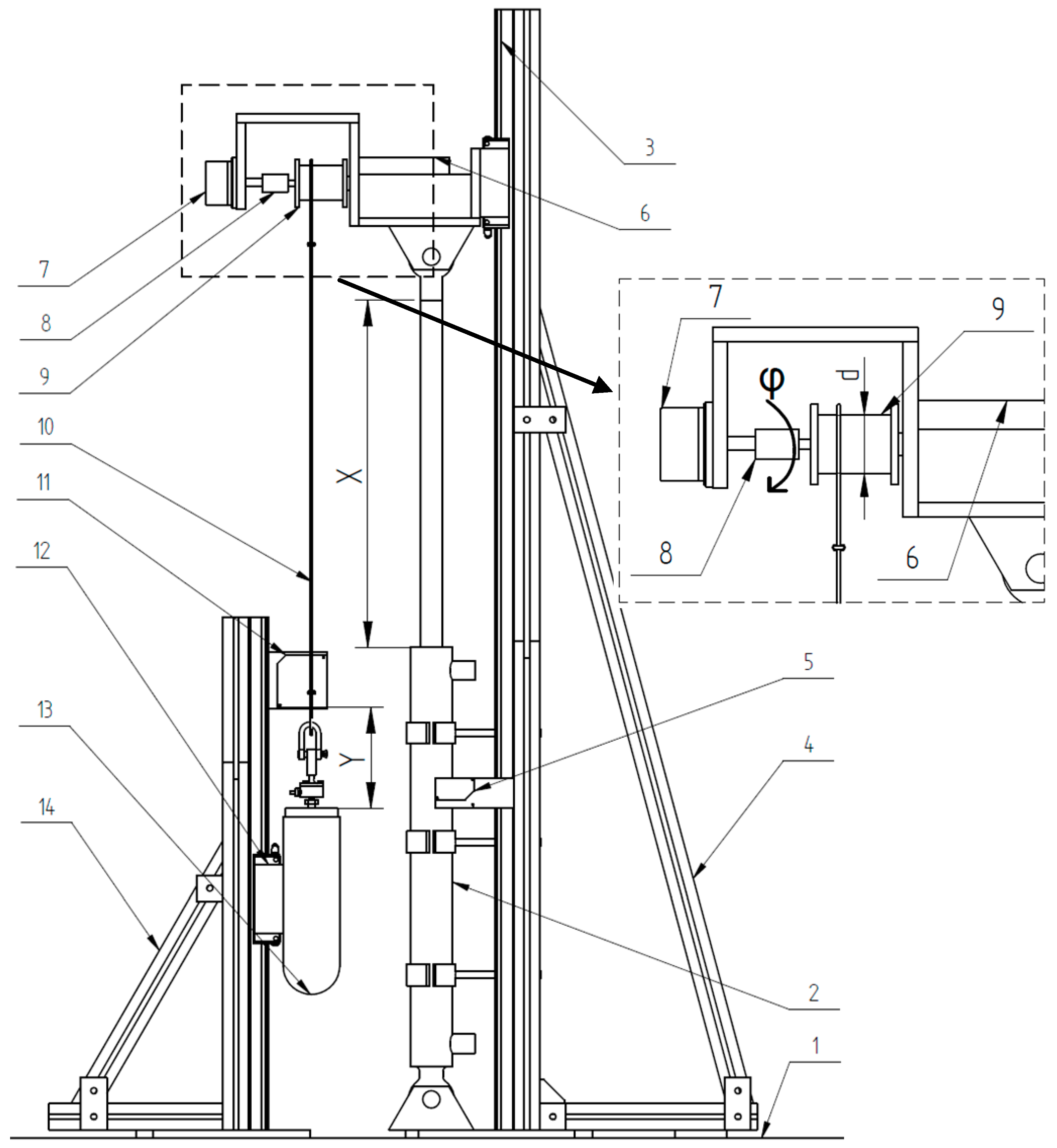
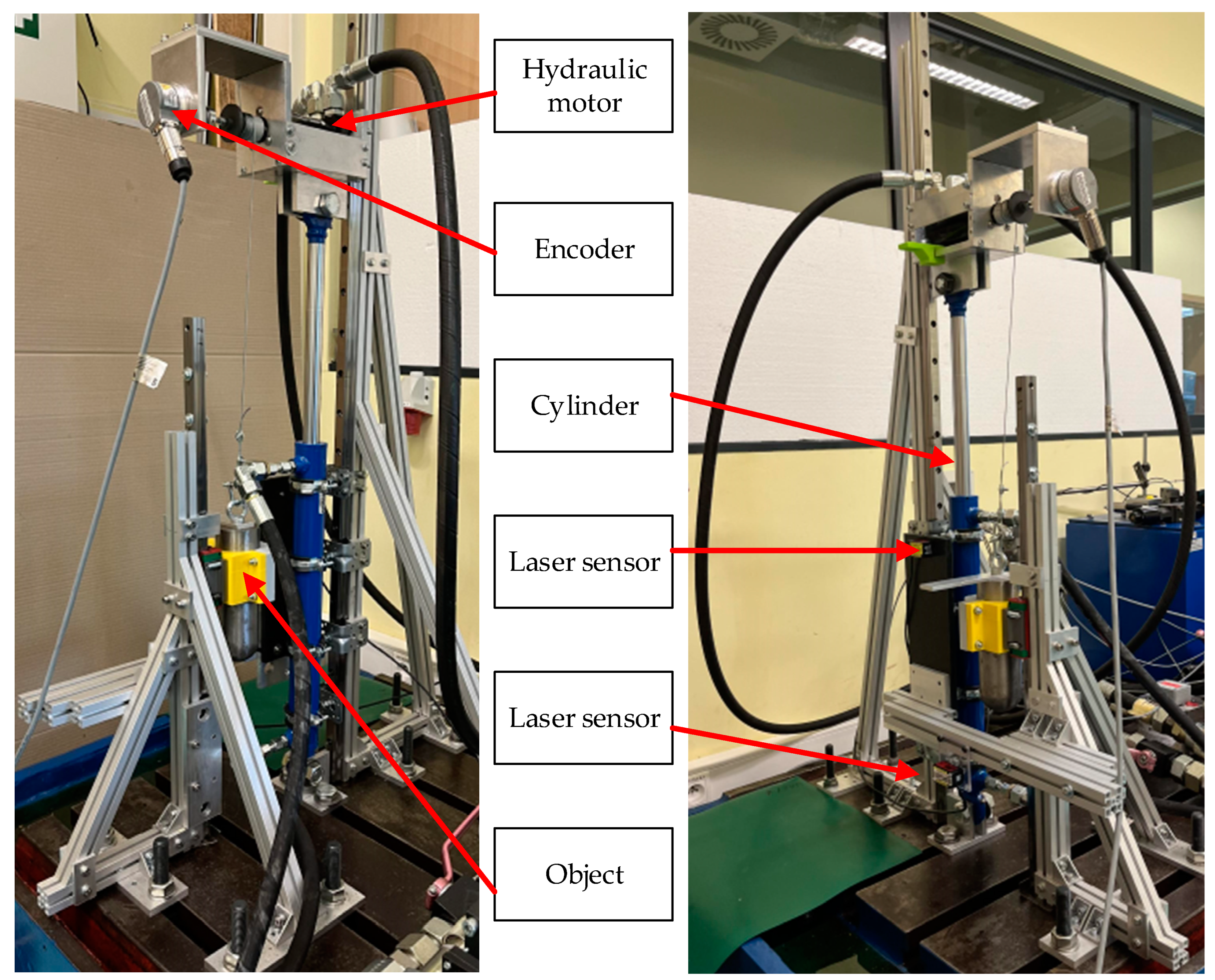
2. Linear Rotary Electro-Hydraulic Servo Drive Unit

The positioning of the object is carried out by the operation of both drives at the same time in different proportions. A block diagram for this type of drive operation is shown in Figure 1. For all types of drive unit operation, the position of the cylinder and the hydraulic motor are regulated by regulators that send a given signal to the valve control cards. Moving the slider on a proportional or servo valve will cause the cylinder or motor to move. Two PID controllers were used, a separate PID controller to position the cylinder and the hydraulic motor. An essential element of the drive unit is the control system. It must be specially designed and made to control two drives at the same time.
Figure 2 shows the construction of the linear rotary electrohydraulic drive unit test stand. The test stand consists of a base (1) to which a hydraulic cylinder (2) is attached. The body is attached to the end of the actuator piston rod, which is connected to a linear guide (3). Such a combination allows for blocking the rotation of the actuator piston rod and causes linear movement of the actuator. The hydraulic motor (6) is placed inside the body. A drum (9) is mounted on the shaft of the hydraulic motor, on which a steel cable is wound. The object (13) is attached to the end of the steel cable. The object is attached to the linear guide. This prevents the object from rotating. It can only move vertically. The main elements of the described drive unit are the hydraulic cylinder and the hydraulic motor. The position of the actuator piston rod is measured by the laser displacement sensor (5). The laser displacement sensor (11) is also used to measure the position of the object. The position of the hydraulic motor shaft is measured by an incremental encoder (7), which is connected to its shaft through a coupling. The design of the new electro-hydraulic drive allows the actuator and motor to work separately or at the same time.
Several important assumptions were made when designing the linear rotary servo electrohydraulic drive (Figure 2). It is important that the hydraulic motor is mounted on the end of the cylinder’s piston rod. To make this possible, a special adapter was designed that is mounted on the end of the cylinder’s piston rod. Then, the hydraulic motor is mounted on this adapter. The construction of the adapter allows for the installation of any hydraulic motor of the SMM series. The speed range of the motors in this series is between 400 and 1950 rpm. Another key element is the drum (9) on which the steel cable is wound. It can be quickly changed to another diameter in the range of 20–60 mm. Due to this, we can regulate the speed of winding and unwinding of the steel cable. To avoid excessive stresses between the hydraulic motor shaft and the encoder, coupling is used. The elements holding the linear guide of the cylinder (4) and the linear guide of the object (14) are made of aluminum profiles. The construction is bolted, which facilitates assembly and allows for quick, easy, and cheap modifications. Many studies have shown that the movement of the object on the horizontal axis and the rotation on the vertical axis are small. For this reason, the object was fitted to the linear guide. Due to this, the movement of the object is only on the vertical axis, and the position measurement is only on the vertical axis.
In rotational motion, the quantity analogous to linear displacement is the angular displacement φ. The angle φ defines the (angular) position of point P relative to the reference frame. The relationship φ = s/R between the linear path s and the angular displacement φ results directly from the angle arc measurement of the angle φ. In rotation, the analogous value of the instantaneous linear velocity v is the instantaneous angular velocity ω.
ω = d φ dt = 1 R ds dt = v R
The relationship φ = s/R between the linear path s and the angular displacement φ results directly from the angle arc measurement of the angle φ.
φ = s R
The encoder resolution is 1000 pulses per revolution. Assume the following:
2 π R 1000   puls rev
On the basis of the above formulas and data, the formula for converting rotational motion into linear motion was determined (4). The following formula (4) has been implemented in the PLC. The use of the encoder described above allowed us to obtain a resolution of the linear motion converted from the rotational motion of the hydraulic motor at the level of 0.095 mm.
s = 2 π R x p 1000   mm
where
  • φ—angular displacement [rad],
  • R—drum radius [mm],
  • xp—measured number of pulses,
  • s—linear distance [mm].
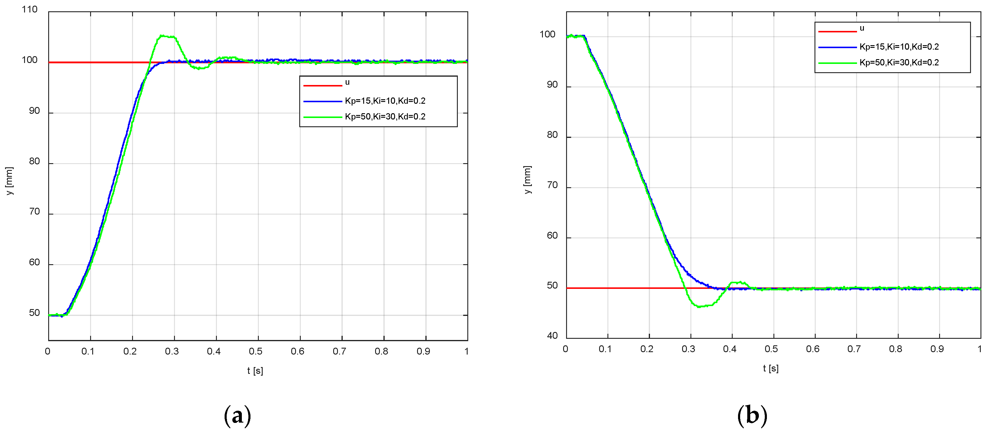
3. Investigation

In Figure 3, the control system diagram for a new electrohydraulic drive solution is presented. The control system was based on a Power Panel 500 PLC. The PLC was equipped with a touch panel. Written software was used that enables easier integration with the user through dedicated visualization. The panel displayed graphs on which current parameters could be read, such as the actuator position, motor position, and object position. The use of a modular PLC controller allowed for quick and easy connection of additional measuring elements.
On the test stand, the first actuator of the servo drive is a single acting cylinder with a piston diameter of 40 mm; the diameter of the piston rod is 22 mm, and the stroke is 400 mm. The second actuator is a hydraulic motor. The maximum rotational speed is 400 rpm. The maximum achievable torque is 58 Nm. The maximum flow for the engine is Q = 20 dm3/min. The maximum motor output power is 2.1 kW. The actuator is mounted in a vertical position. A special plate is mounted to the end of the piston rod. The motor is bolted to the plate, on the shaft of which there is a drum. A steel cable is wound around this shaft. The drum diameter is 30 mm. The object is attached to the end of the steel cable. The position of the piston rod of the cylinder is measured using the HG-C1400 laser displacement sensor from Panasonic Company. The sensor measurement range is ±200 mm, and the measurement center distance is 400 mm from the object. The repeatability in the range of 200–400 mm is 300 μm. A second laser displacement sensor HL-C1200 from Panasonic Company is used to measure the position of the object. The sensor measurement range is ±80 mm, and the distance of the measurement center is 200 mm from the object. The repeatability is equal to 200 μm. The position of the hydraulic motor shaft is measured using an incremental encoder. To avoid free movement of the object, it was decided to limit the movement of the object to vertical movement only. A linear guide with a linear carriage from HIWIN Company is used to obtain the vertical movement of the object. The guide is mounted in a vertical position; the object is attached to the guide carriage. It is also necessary to limit the movement of the cylinder piston rod. The piston rod moves only vertically. Blocking the rotation of the actuator piston rod is ensured by screwing the appropriate adapter onto the piston rod, which is then mounted on the linear carriage. The linear guide is vertically mounted on the rail on which the linear carriage is mounted. The test stand is shown in Figure 4.
The hydraulic elements on the test stand are powered by a hydraulic power unit with the following parameters: maximum flow Q = 100 dm3/min, maximum pressure p0 = 40 MPa, engine power = 37 kW, and filtration at the 6-micron level.
First, the influence of the PID controller parameters on the cylinder step response was checked. The PID controller was used to test the step response of the cylinder. The step responses for the up- and downward movements of the cylinder were checked. The supply pressure of the hydraulic system for all tests was p0 = 8 MPa. Figure 5 shows the change in the position of the piston rod of the cylinder for various parameters of the PID controller. Tests were carried out for the up- and downward movements. For the constructed system, the selection of PID controller parameters was carried out using a closed-loop autotuner block, which allows tuning the PID controller for the real object. Matlab software was used for this purpose. The start position for the upward movement was equal to 50 mm, and the set position was 100 mm. For the downward movement, the start position was equal to 100 mm, and the set position was 50 mm. In the waveforms (Figure 5), the set signal is marked in red, and the cylinder response to the step input for various parameters of the PID controller is marked in blue and green. The blue waveform shows no overregulation. The course with overregulation is marked in green. Similarly, on the cylinder, hydraulic motor motion tests were carried out, with the hydraulic motor moving to the right or to the left. The rotational motion of the hydraulic motor was converted into linear motion according to the formulas given above. The movement of the motor to the right corresponds to the movement of the cylinder upward. The movement of the motor to the left corresponds to the movement of the cylinder downwards. The cylinder moves up and down at different speeds. This is due to the difference in the surface area on which the hydraulic oil acts. This effect does not occur with a hydraulic motor—the speeds of movement in both directions are the same. From the waveforms obtained, it can be concluded that the linear speed (calculated from the rotational motion) of the motor is higher than that of the cylinder. The response of the hydraulic motor to step excitation is shown in Figure 6. Figure 5 and Figure 6 show the symbols kp—gain of the PID controller, ki—gain of the integrating part, and kd—gain of the derivative part. During the experimental studies, the effects of the hydraulic oil temperature and its compressibility were omitted.
The next step was to study the step response of the object using the cylinder and the hydraulic motor that operate at the same time. In these tests, the position of the object suspended on a steel cable was measured. Tests were carried out for the up- and downward movements of the object. The movement of the object was carried out by means of a hydraulic motor and the cylinder. Various variants of the contribution of each of these drives to the total motion were investigated. In the first case, the hydraulic motor accounted for 70% of the movement and the cylinder for 30% of the movement. The waveforms from these tests are shown in Figure 7. Second, tests were carried out in which the share of the hydraulic motor in the movement of the object was 30%, while the share of the actuator was 70%. The waveforms collected are shown in Figure 8. Comparing the graphs in Figure 7 and Figure 8, it can be stated that the speed of movement in the case of the actuator’s share of 30% and the motor’s share of 70% is higher than that in the reverse case.

4. Discussion

The built linear rotary electrohydraulic servo drive enables the testing of each drive separately and both drives together. The tests carried out have shown that it is possible to simultaneously control both drives so as to obtain a higher speed of the object’s movement than in the case of the movement of each drive separately. The hydraulic motor turned out to be faster than the cylinder. The limit of each actuator is its stroke. In the case of the motor, there is no limitation of movement in the form of a stroke. This is a great advantage when the motor is used as a drive where large displacement is required. The actuator can then be used as an additional element that improves positioning accuracy. In earlier works, various sizes of motors and cylinders were tested. Tests were also carried out at different values of the hydraulic system supply pressure. Basic step response tests were performed on both drives to verify the maximum speeds. In future work, we plan to carry out tests with different shares in the movement of each of the drives and to determine the positioning of the object. We plan to perform positioning tests of the suspended object during the operation of both drives simultaneously. In the control system, the position of the object will be a feedback signal. We plan to use other control algorithms, e.g., model predictive control.

Author Contributions

Conceptualization, A.J. and A.M.; methodology, A.J. and A.K.; resources, A.J.; data curation, A.J. and A.K.; writing—original draft preparation, A.J. and A.M.; writing—review and editing, A.J. and A.K.; visualization, A.J.; supervision, A.M. and A.K.; project administration, A.J.; funding acquisition, A.M. All authors have read and agreed to the published version of the manuscript.

Funding

This work was supported by the Polish Ministry of Science and Education grant no. 0614/SBAD/1565.

Institutional Review Board Statement

Not applicable.

Informed Consent Statement

Not applicable.

Data Availability Statement

Not applicable.

Conflicts of Interest

The authors declare no conflict of interest.

References

  1. Murrenhoff, H. Fundamentals of Fluid Power; Hydraulics Part 1; Shaker Verlag GmbH: Aachen, Germany, 2014. [Google Scholar]
  2. Chapple, P. Principles of Hydraulic Systems Design, 1st ed.; Coxmoor Publishing Company: Chipping Norton, UK, 2003. [Google Scholar]
  3. Rabie, M.G. Fluid Power Engineering; McGraw Hill Professional: New York, NY, USA, 2009; ISBN 978-0-07-162606-4. [Google Scholar]
  4. Backe, W. Untersuchung des Einflusses von Störkräften auf den Schaltvorgang bei Wegeventilen der Hydraulik; Springer: Berlin/Heidelberg, Germany, 1975. [Google Scholar] [CrossRef] [Green Version]
  5. Akers, A.; Gassman, M.; Smith, R. Hydraulic Power System Analysis; CRC Press: Boca Raton, FL, USA, 2006. [Google Scholar] [CrossRef]
  6. Moog, Electro-Hydraulic Valves—A Technical Look; Electro-Hydraulic Valves; Moog Inc.: New York, NY, USA, 2016.
  7. Rybarczyk, D. PLC Implementation of Fractional PI Controller in Positioning of Electrohydraulic Servodrive. Control. Cybern. 2016, 45, 301–316. [Google Scholar]
  8. Wos, P.; Dindorf, R. Adaptive Control of the Electro-Hydraulic Servo-System with External Disturbances. Asian J. Control. 2013, 15, 1065–1080. [Google Scholar] [CrossRef]
  9. AL-Assady, A.A.M.H.; AL-Khafaji, M.T.J. Design and Analysis of Electro-Hydraulic Servo System for Speed Control of Hy-draulic Motor. J. Eng. 2013, 19, 562–573. [Google Scholar] [CrossRef]
  10. Entao, Z.; Wenlin, Y.; Junzhe, L. Predictive Control of Hydraulic Winch Motion Control. In Proceedings of the 2009 2nd IEEE International Conference on Computer Science and Information Technology, Beijing, China, 8–11 August 2009; pp. 1–4. [Google Scholar]
  11. Sato, Y. Rotational Speed Control of Hydraulic Motor Using Sliding Mode Control. Trans. Jpn. Soc. Mech. Eng. Ser. C 2001, 67, 2559–2564. [Google Scholar] [CrossRef] [Green Version]
  12. Sinthipsomboon, K.; Hunsacharoonroj, I.; Khedari, J.; Pongaen, W.; Pratumsuwan, P. A Hybrid of Fuzzy and Fuzzy Self-Tuning PID Controller for Servo Electro-Hydraulic System. In Proceedings of the 2011 6th IEEE Conference on Industrial Electronics and Applications, Beijing, China, 21–23 June 2011; pp. 220–225. [Google Scholar]
  13. Tran, N.H.; Le, C.; Ngo, A.D. An Investigation on Speed Control of a Spindle Cluster Driven by Hydraulic Motor: Application to Metal Cutting Machines. Int. J. Rotating Mach. 2019, 2019, 4359524. [Google Scholar] [CrossRef]
  14. Woś, P.; Dindorf, R. Synchronization of the movement for multi-cylinder electrohydraulic servo driver. In Proceedings of the EPJ Web of Conferences, Santiago de Compostela, Spain, 24–28 October 2022; EDP Sciences: Ulis, France, 2022; Volume 269, p. 01069. [Google Scholar]
  15. Shen, J.; Cui, H.; Feng, K.; Zhang, H.; Li, H. Parameter identification and control algorithm of electrohydraulic servo system for robotic excavator based on improved hammerstein model. Math. Probl. Eng. 2020, 2020, 9216019. [Google Scholar]
  16. Yang, J.; Liu, B.; Zhang, T.; Hong, J.; Zhang, H. Application of energy conversion and integration technologies based on electro-hydraulic hybrid power systems: A review. Energy Convers. Manag. 2022, 272, 116372. [Google Scholar] [CrossRef]
  17. Zhou, S.; Shen, C.; Xia, Y.; Chen, Z.; Zhu, S. Adaptive robust control design for underwater multi-dof hydraulic manipulator. Ocean. Eng. 2022, 248, 110822. [Google Scholar] [CrossRef]
  18. Petrović, G.R.; Mattila, J. Mathematical modelling and virtual decomposition control of heavy-duty parallel–serial hydraulic manipulators. Mech. Mach. Theory 2022, 170, 104680. [Google Scholar] [CrossRef]
  19. Zhang, X.; Shi, G. Dual extended state observer-based adaptive dynamic surface control for a hydraulic manipulator with actuator dynamics. Mech. Mach. Theory 2022, 169, 104647. [Google Scholar] [CrossRef]
  20. Luo, S.; Cheng, M.; Ding, R.; Wang, F.; Xu, B.; Chen, B. Human–Robot Shared Control Based on Locally Weighted Intent Prediction for a Teleoperated Hydraulic Manipulator System. IEEE/ASME Trans. Mechatron. 2022, 27, 4462–4474. [Google Scholar] [CrossRef]
  21. Zhang, J.; Yuan, Z.; Dong, S.; Sadiq, M.T.; Zhang, F.; Li, J. Structural Design and Kinematics Simulation of Hydraulic Biped Robot. Appl. Sci. 2020, 10, 6377. [Google Scholar] [CrossRef]
Figure 1. Block diagram of the control system for object positioning.
Applsci 13 08598 g001
Figure 2. Simplified drawing of the linear rotary electro-hydraulic drive.
Applsci 13 08598 g002
Figure 3. Diagram of the control system.
Applsci 13 08598 g003
Figure 4. Test stand view.
Applsci 13 08598 g004
Figure 5. Positioning of the cylinder for different parameters of the PID regulator: (a) upward movement, (b) downward movement.
Applsci 13 08598 g005
Figure 6. Positioning of the hydraulic motor for different set values: (a) upward movement and (b) downward movement.
Applsci 13 08598 g006
Figure 7. Positioning of the object using the cylinder (30%) and the hydraulic motor (70%): (a) upward movement, (b) downward movement.
Applsci 13 08598 g007
Figure 8. Positioning of the object using the cylinder (70%) and the hydraulic motor (30%): (a) upward movement, (b) downward movement.
Applsci 13 08598 g008
Disclaimer/Publisher’s Note: The statements, opinions and data contained in all publications are solely those of the individual author(s) and contributor(s) and not of MDPI and/or the editor(s). MDPI and/or the editor(s) disclaim responsibility for any injury to people or property resulting from any ideas, methods, instructions or products referred to in the content.

