Article

Supervision System 4.0 for a Road Tanker Washing Robot Manipulator

by
Luís Vicente
1,2,
Fernando Carreira
1,3,
Francisco M. Campos
1,
Mário J. G. C. Mendes
1,4,*,
João M. F. Calado
1,3 and
Gamboa Carvalho
2
1
ISEL—Instituto Superior de Engenharia de Lisboa, Instituto Politécnico de Lisboa, 1959-007 Lisbon, Portugal
2
CARMONA—Sociedade de Limpeza e Tratamento de Combustíveis, S.A., 2925-201 Azeitão, Portugal
3
LAETA/IDMEC—Instituto de Engenharia Mecânica, 1049-001 Lisbon, Portugal
4
CENTEC—Centre for Marine Technology and Ocean Engineering, 1049-001 Lisbon, Portugal
*
Author to whom correspondence should be addressed.
Appl. Sci. 2023, 13(14), 8500; https://doi.org/10.3390/app13148500
Submission received: 13 June 2023 / Revised: 20 July 2023 / Accepted: 21 July 2023 / Published: 23 July 2023

Abstract

:
The washing of road tankers is currently still a manual process that requires an operator to place the washing head into the tanks. To increase productivity and operator safety, it is essential to implement automated systems with Fault Detection and Isolation (FDI) capabilities. On the other hand, the industry 4.0 paradigm promotes the use of collaborative systems that integrate with the other organization’s processes. Realizing this new vision requires Supervision, Control and Data Acquisition (SCADA) systems with FDI modules that integrate with collaborative systems and promote the digitalization of companies. This paper proposes a SCADA system for a new road tanker washing robot, aimed at integrating all systems and communication networks of the organization and future FDI modules. To this end, this paper proposes a communication architecture based on open protocols and a common database to connect SCADA to the lower and higher levels of automation. Furthermore, this paper describes the various aspects of SCADA system development, from synoptic design to validation. To support the development of the SCADA system, a Digital Twin (DT) of the road tanker washing robot was used, allowing to test and validate its functionality through this virtual prototype. The results show that the proposed SCADA system and underlying information architecture are suitable for supervision of a robotized wash operation and that the use of a Digital Twin facilitates SCADA system design and validation.

1. Introduction

Fault Detection and Isolation (FDI) systems are critical for ensuring the safe and efficient operation of industrial processes. With the advent of Industry 4.0, there has been a renewed focus on developing advanced FDI systems to handle the increased complexity and variability of modern industrial systems [1,2]. New insights into FDI systems for Industry 4.0 highlight the importance of data-based approaches and the opportunities presented by increased computing capacity, as Industrial Information Technology (IIT) now has greater processing capacity available near the factory floor—edge computing—and in the transition and analysis of data between the factory floor and the cloud—fog computing [3]. Another important insight is the need for more flexible and adaptable FDI systems. While in the past FDI systems were often designed for specific systems or equipment, today it is becoming increasingly important for FDI systems to be more versatile. This requires the use of general-purpose algorithms and machine learning techniques that can be adapted to different contexts. Finally, there is a growing recognition of the importance of human–machine collaboration in FDI systems for Industry 4.0. While advanced algorithms and techniques can greatly improve the performance of FDI systems, it is still important for operators and other human personnel to be involved in the process [4]. By providing clear and actionable information to operators, FDI systems can help them make informed decisions and take more effective actions to address faults [5].
Overall, the development of advanced FDI systems for Industry 4.0 is a challenging and ongoing process. Nevertheless, new insights and technologies are leading to FDI systems that are more efficient, reliable and effective than ever before [6]. This work focuses on a proposal for a supervisory system for a road tanker washing robot, designed in the context of industry 4.0, that enables the integration of the following technologies: Digital Twin (DT), quality control based on machine learning (ML) algorithms, FDI and the Industrial Internet of Things (IIoT). The supervision system includes a Human–Machine Interface (HMI) that complies with the ANSI/ISA-101.01-2015 guidelines and an architecture that allows the various systems and software in a factory to be easily and efficiently connected. The system supports machine-to-machine (M2M) communication and therefore can integrate FDI or the ML-based quality control modules in future developments without the need to stop processes.
Supervision systems have been introduced in several areas since the 1940s and have become increasingly dominant. The first computer-based Supervision, Control And Data Acquisition (SCADA) systems appeared in the 1960s and, until the 1980s, usually relied on a centralized architecture, in which a single machine was responsible for managing and performing all control and data acquisition functions [7]. From the 1980s, SCADA systems began to use distributed architectures following the introduction of the Local Area Network (LAN), and later (1990s), open system architectures were introduced to replace vendor-controlled architectures [8].
Over time, SCADA systems have become more complex as new functions have been introduced. These were implemented on a networked system consisting of servers, HMI and Programmable Logic Controllers (PLCs) [9]. These systems currently provide the ability to control, supervise and store data in real time. With the Fourth Industrial Revolution, it is now required for SCADA network systems to be integrated with the other communication networks of organizations. This feature underlies the Industry 4.0 paradigm, where all communication networks are integrated through the Industrial Internet of Things (IIoT) and support the creation of a Cyber-Physical System (CPS) [10]. Given the prominent role of SCADA systems in plant operations, it is essential that these systems are fully integrated into this communication infrastructure. One of the advantages of integrating SCADA with CPSs is the ability to simulate the operation of a real system with a DT [11]. The availability of a DT that matches the physical process allows the functionalities of the SCADA system to be tested at the same time as the mechanical design, production and installation phases are being developed. This allows to reduce the development time of new systems and to validate their operation before they are produced [12,13]. In addition, a DT allows new operation cycles to be tested without the need to stop the physical system operation or even testing the system’s responses in the event of a failure or malfunction. In addition to allowing testing of the control logic, a DT is also useful for testing the supervision interfaces and the communication between different systems. For instance, operators can visualize the response to their actions through the DT, while testing the HMI interface of the SCADA system. Supervision interfaces can then be improved based on the users’ feedback, thus reducing the adaptation period when the supervision system is implemented. Finally, DTs can also be used to assess the risk of occupational injuries and accidents to human workers in industrial workplaces [14].
In recent years, increasing attention has been paid to creating DTs for gantries and other types of robotic manipulators. For instance, in [15], the authors developed a DT for a gantry robot used in automated wood furniture production. The DT was used to simulate robot trajectories and aid in the planning of efficient and collision-free robot trajectories, using the NavMesh algorithm. In [16], a DT was developed for a multigantry system used in the ship building industry to manipulate hull parts. The simulation capabilities of the DT were used to optimize resource allocation in real time during production. A DT of a knuckle boom crane is presented in [17]. In that work, stress analysis is carried out in the DT to perform condition monitoring of the real system. For this purpose, the authors resort to a finite element model which is validated against a physical prototype. In contrast to the previously mentioned works, this paper focuses on the integration of a DT into a SCADA system and the use of the DT to validate the SCADA services.
Nowadays, in the tank cleaning industry, the washing of road tanker trucks is done manually, with professionals positioning (manually) the washing system at the man entrance. Operators often must enter the road tanker truck to carry out difficult cleanings (often with toxic products), thus being exposed to the risks associated with this work. The entire process is done without automatic supervision, and all activity, maintenance, faults and malfunctions are also recorded manually. For this reason, the work developed in this paper is of the utmost importance for road tanker cleaning companies (and their workers) seeking digital transformation and automatic washing, control and supervision systems.
The SCADA system proposed in this paper (and in previous work [18]) manages the automatic washing of road tanker trucks, the control and supervision of the entire washing system and complies with some of the requirements of industry 4.0. Namely, the proposed SCADA system leads to the digital transformation of the entire washing process and supports supervision via Internet, the use of a Digital Twin for process simulation and optimization, machine-to-machine communication, incorporation of fault diagnosis and alarm management and automatic generation of reports. In this way, professionals in this sector benefit from greater safety at work and companies will be able to improve the efficiency of their washing processes, thus reducing costs.
One of the goals of this work is to develop a SCADA system under the industry 4.0 principles. Specifically, the present work focuses on the application of these principles to supervise a new road tanker washing robot.
In brief, the paper contributes to the current state of the art with the following:
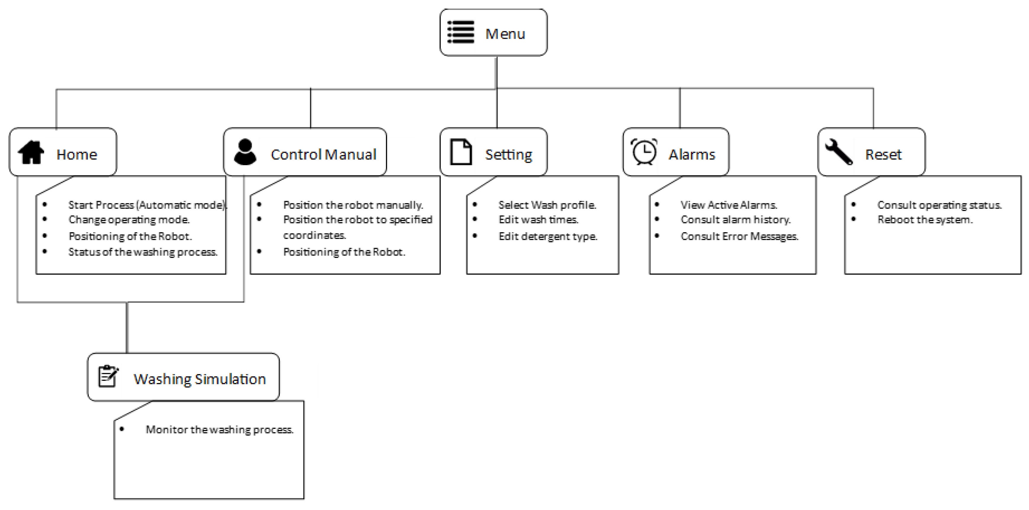
  • The development of the SCADA system and HMI to supervise a washing robot manipulator introduced in [18]. The proposed SCADA handles aspects of the system such as parameter profiles for different washing tasks, operation of the robot in manual or automatic mode and management of different user profiles.
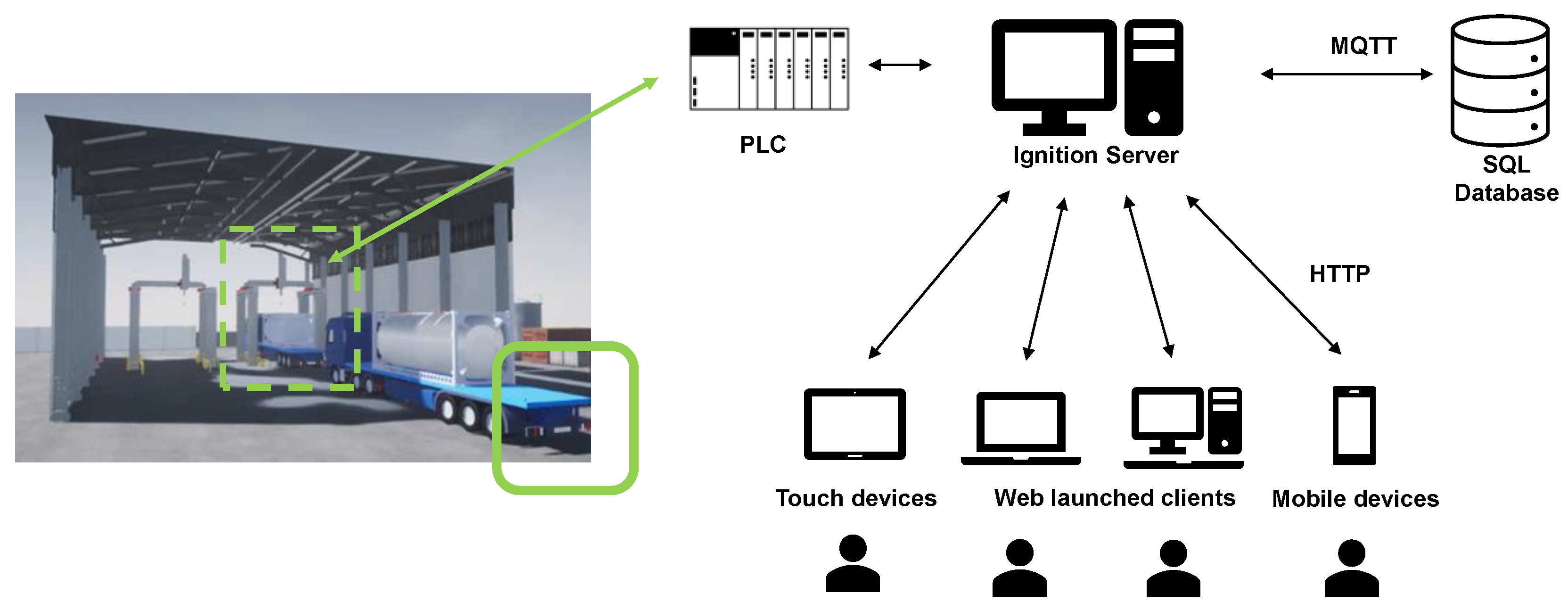
  • A SCADA architecture based on open communication protocols in which the real system and the DT can be easily integrated.
  • The demonstration of the validation of a SCADA system supported by a Digital Twin.
This paper describes the current developments of the work presented in [18], where the road tanker washing robot and the corresponding DT were first introduced. This paper is divided into the following sections: Section 2 presents the road tanker washing robot; Section 3 presents the SCADA 4.0 system; Section 4 describes the DT-based validation of the SCADA system and Section 5 presents the conclusions.

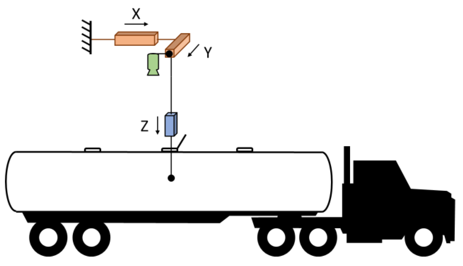
2. Road Tanker Washing Robot

In typical washing stations, the washing of a road tanker is carried out by washing heads that eject water and detergent in all directions. These washing heads are manually inserted into the tank by operators. Due to the excessive human effort and danger involved in such tasks [19,20], there is a need to robotize and automate this process.
To automate the insertion of the washing head into the tank, a robot manipulator was used. Although tanks are standardized, there are several possible configurations, which differ in the number of manholes and the layout. In addition, the relative position of the man entry to the robot also varies depending on the truck position. It is therefore clear that besides the vertical movement needed for the washing head insertion, additional DoFs (Degrees of Freedom) are needed to meet these variability factors. To meet these requirements, a servo-controlled cartesian robot manipulator was adopted, whose X and Y are, respectively, aligned to the transverse and longitudinal directions of the truck (see Figure 1).
To determine the position of the manholes within the robot’s workspace, a computer vision system is used. This is achieved through a camera that is attached to the Y axis of the robot and, thus, moves in the XY plane but not in the Z direction (see Figure 1).

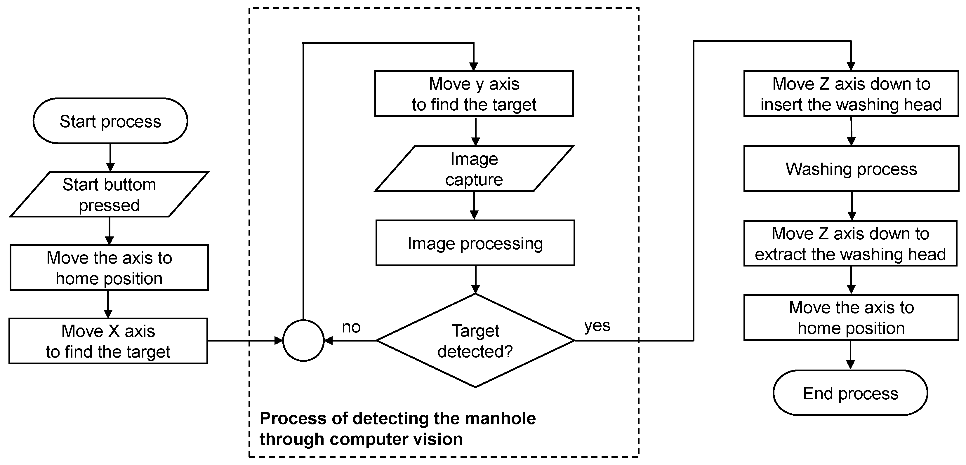
2.1. Operation Cycle of the Road Tanker Washing Robot

The robotic task can be divided into three main phases, namely (i) searching for the manhole, (ii) washing and (iii) returning to the home position. These phases can be further divided into several steps, as described in the flowchart in Figure 2. Among the various steps that make up the operation cycle, step 3 stands out as the process of detecting the manhole through computer vision. In this step, images are captured while the robot follows a predefined path, which is interrupted when a manhole is found.
The operating cycle is initialized by an operator by issuing the “START” command through the HMI. The HMI displays the synoptic elements that are needed to establish communication between the operator and the equipment and to display the necessary information for the operation and parameterization of the robot manipulator. As a fundamental part of a SCADA system, the supervisory synoptics are discussed in the next section.

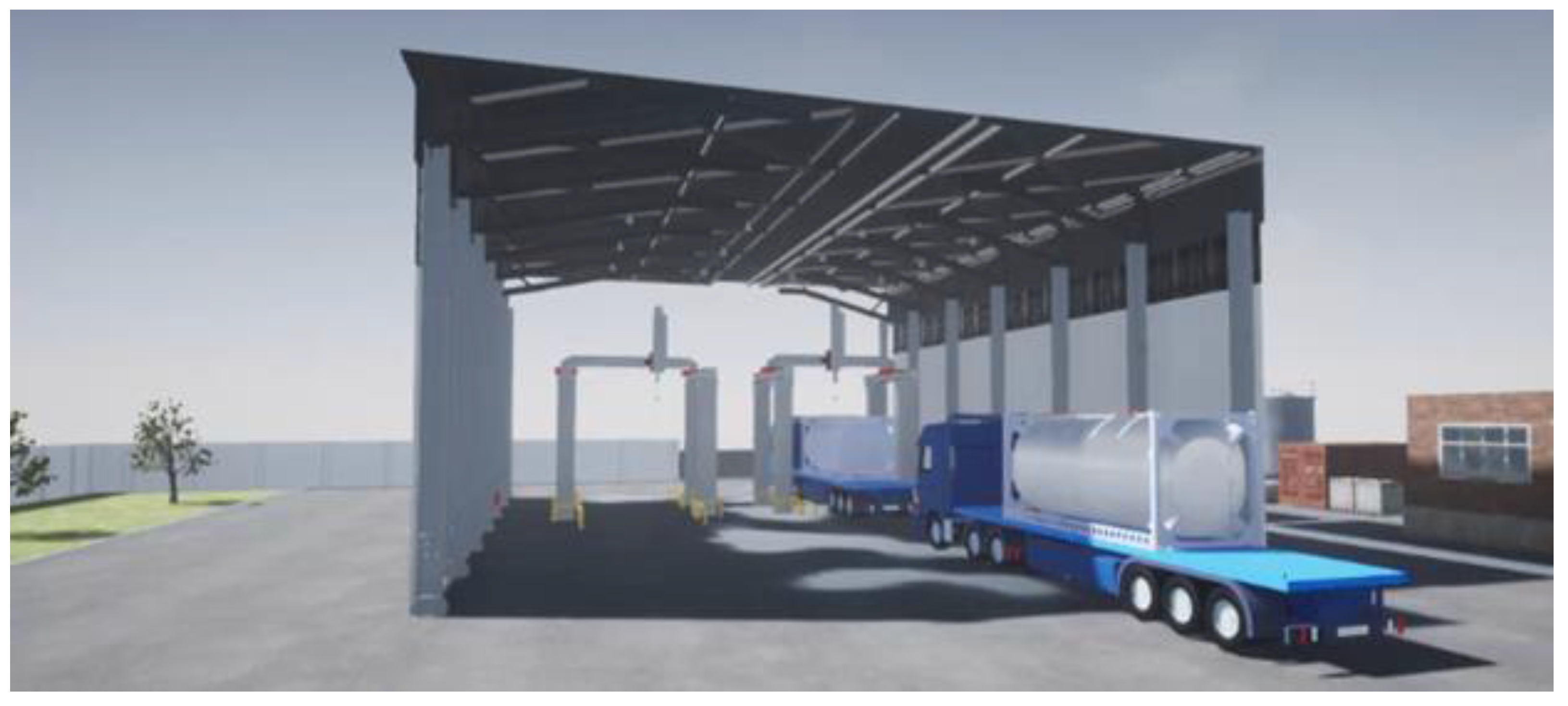
2.2. Digital Twin of the Road Tanker Washing Robot

Since the manipulation robot has not yet been produced, a DT of the robot, introduced in [18], was used to develop and test its SCADA system. Since one of the goals is to test computer-vision-based control algorithms, a required feature of the DT was a high level of photorealism. This was achieved by resorting to the Unreal Engine, which provides state-of-the-art rendering mechanisms to synthesize photorealistic images (see Figure 3). This allowed the simulation of varied and extreme illumination conditions, which can crucially impact the success of the image analysis. In addition, the DT was prepared to simulate a range of error conditions, such as an interrupted communication link to the image acquisition device and to the control drives of the individual robot axes.
In [18], the DT was used to validate the control logic described in the previous section and the image processing algorithm for manhole detection. In this work, the DT information is further used to validate the operation of the SCADA system. For example, the correct operating protocols can be verified in the event that a manhole is not detected due to insufficient lighting conditions (see ‘Alarm service validation’ in Section 4).
For a more detailed description of the washing robot and its DT, the reader is referred to [18], where these systems are introduced.

3. SCADA 4.0 System

To integrate the road tanker washing system with the factory systems, a SCADA 4.0 system was developed. This system incorporates the functionalities of a traditional SCADA system and the new concepts introduced by Industry 4.0. This approach is motivated by the need for a collaborative infrastructure for the tank washing system to continuously monitor the status of the process and facilitate the exchange of information within the organization.
As previously described, most SCADA systems today are developed through dedicated software packages. Accordingly, the proposed SCADA system was developed based on a commercial SCADA software (version 8.1.11) platform. Several companies provide SCADA software platforms such as Siemens®, ABB® and Rockwell Automation®, among others. However, the SCADA software platforms provided by most companies are limited to communication with their own control hardware. Among the various SCADA software platforms, Ignition (version 8.1.11), provided by Inductive Automation®, stands out for allowing its installation in any operating system and connecting to any brand of PLCs/HMIs [21]. In addition, Ignition is also attractive for providing a platform based on IIoT and open protocols, for supporting a range of user interface devices (total mobility) and offering cybersecurity techniques. Adding to these, Ignition also features scalability, i.e., the ability to update each project according to the user needs, allowing to expand its base architecture. The comparison of these features with the corresponding features of other software led to the selection of Ignition for the development of the proposed SCADA system.

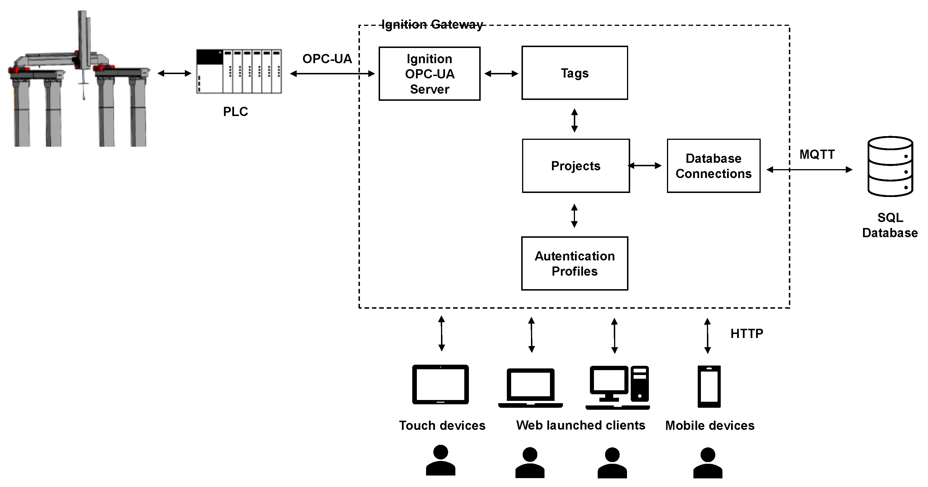
3.1. SCADA System Architecture

Depending on the size and complexity, SCADA systems can be developed according to different architectures. In this work, the SCADA system architecture (see Figure 4) is centered on a server running the Ignition Gateway and permanently connected to the Internet. This server is connected to the PLC that controls the robot manipulator and to a database that stores the collected data. To control and supervise the process, operators can connect to the server through any device supporting the standard Internet protocols (Transmission Control Protocol/Internet Protocol (TCP/IP) and Hypertext Transfer Protocol Secure (HTTPS)), such as computers, tablets and smartphones.
In the proposed SCADA system, the database server that stores the data history is installed on the same computer that runs the Ignition server. However, this database may exist in a different computer or even in the cloud and be accessed by the Ignition server once it is connected to the Internet. The connection between the Ignition server and the PLC is established by standard industry 4.0 protocols, such as the Open Platform Communications Unified Architecture (OPC UA) and Message Queuing Telemetry Transport (MQTT). This SCADA system architecture is highly scalable, as it allows the addition of other control devices, database servers or applications that may be needed to meet new system requirements, such as FDI features.
The operation of the real system and/or the DT can be easily integrated into this architecture, with the PLC acting as an intermediary. In particular, the control program executed by the PLC should be able to (i) send command signals to the real system and/or the photorealistic DT; (ii) read signals from real and virtual sensors and select one or the other for the control logic; and (iii) write all these signals to the database so that they can be accessed by the SCADA and FDI systems. When these conditions are met, the system enables the following modes of operation:
DT control—The PLC reads signals from the DT and returns command signals to the DT;
Real system control—The PLC reads signals from the real system and returns command signals to the real system;
Control of the real system with DT-based monitoring—The PLC reads signals from the real system and calculates the corresponding control signals that are applied to the real system and the DT. At the same time, signals from the virtual sensors are also read and all data are written to the appropriate database. The real and model signals can then be compared by the SCADA or FDI system for fault detection and alarm reporting.

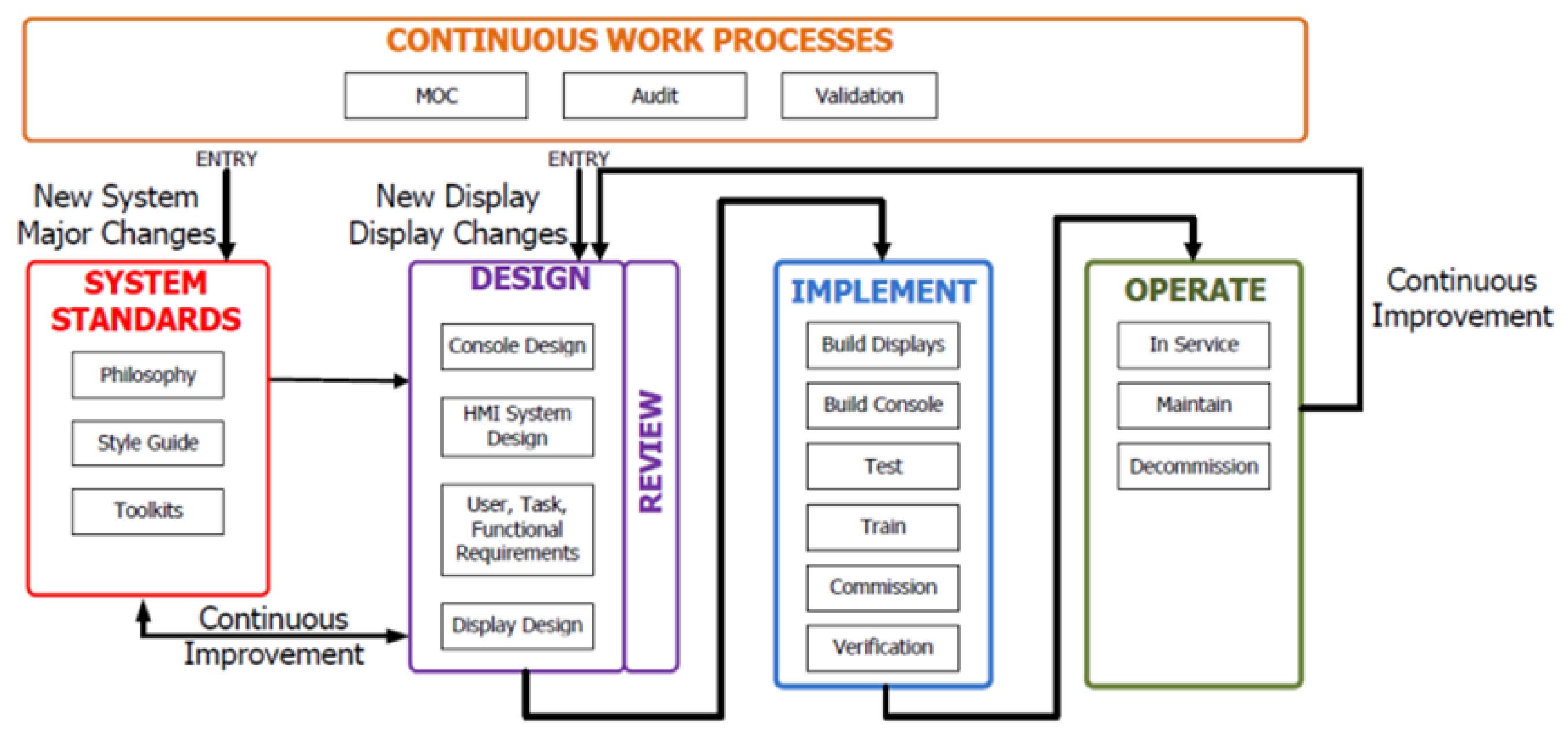
3.2. SCADA 4.0 Software

The ISA101:2015 standard establishes a life cycle for the development, implementation and maintenance of SCADA systems encompassing five main stages: conception, planning, design, implementation and operation and maintenance. Figure 5 graphically represents the five stages that make up the life cycle. The adoption of this life cycle aims at guaranteeing the efficiency, security and reliability of SCADA software.
In accordance with this life cycle, the first step in the development of the SCADA system was the definition of the objectives and technical specifications. Among other aspects, this led to the definition of the security requirements and the characteristics of the synoptics to be developed. In the second stage, all the steps of the project planning were carried out. In the third stage, all SCADA software functionalities were developed. In this stage, the design, architecture of the SCADA software and the various functions that it should perform were elaborated.
Next, the various services developed for the SCADA system are detailed.
  • The robotic washing system supervision by the SCADA 4.0 system.
The purpose of the supervision and control function is to inform system operators about the system state in real time. In traditional SCADA systems, process supervision is carried out through HMI interfaces integrated into the production system. By introducing industry 4.0 concepts into the SCADA system, it becomes possible to remotely access the status of processes, thus allowing total mobility for operators. For each application, a set of synoptics was developed that allows operators to access the state of the robot manipulator and to control all washing process.
The control system interfaces are represented in the flowchart of Figure 6. This navigation scheme was designed with the purpose of minimizing the steps necessary to carry out an operation.
All the synoptics were developed following the recommendations of the ANSI/ISA-101.01-2015 standard. Specifically, the control and supervision components were drawn in grayscale and supplemented with animations and bright colors (red and green) to illustrate the process state and anomalous situations through warnings or alarms.
The application for mobile devices was designed to adapt to the device’s screen size, thus ensuring a better user experience. In this way, for screens with a width greater than 500 pixels, the supervision application presents the layout visible in Figure 7a, while the layout for devices with screens smaller than that value is illustrated in Figure 7b. Both applications allow performing the same tasks, with the differences existing strictly in the layout.
2.
Communication in a SCADA 4.0 system
In addition to being a data acquisition and process platform, the SCADA 4.0 system can also be classified as a communication system, given the essential role it plays in the exchange and communication of data in the smart factory context. The SCADA system has the responsibility of connecting the control system to the enterprise’s organization systems. As SCADA systems are in constant communication with command systems, these have privileged access to all process status data.
The SCADA system under construction has the function of transmitting all the process state information with the remaining communication software. For the exchange of information, a database was used that communicates with Ignition through the MQTT protocol. This architecture is represented in Figure 4. The database tables were created to record the washing operations history and the relevant data about the processes status. The SCADA system was also configured to read information from the database. This bidirectional communication between the SCADA system and the database server allows sharing process data with other information systems such as the Manufacturing Execution System (MES) and Enterprise Resource Planning (ERP) system, among others.
The SCADA system connection to the database allows the sharing of the process data with big data analysis software (machine learning, for example), carrying out the necessary analyses to introduce improvements in the process or alert to possible failures or breakdowns.
As the proposed SCADA system supports communication using the standard open protocols of Industry 4.0, whenever new equipment is added to the washing process, it can be integrated into the existing SCADA system, making the M2M communication easier to obtain.
3.
FDI, alarm generation and management
The safety of installations and processes has become increasingly important in production systems. To identify possible faults/failures and solve them in the shortest possible time, an alarm triggering and management function was included in the proposed SCADA 4.0 system. In the event of a fault, it is important that the problem is identified, the appropriate alarm is triggered and a notification is issued. In this sense, whenever a parameter falls outside its safe value range, an alarm is issued by the SCADA system. To categorize the alarms, a criticality scale with five different levels was adopted, and the alarms were categorized according to their severity. The current alarm functionalities will be extended, in the future, with the adoption of FDI systems based on classic and machine learning methodologies. There exist several possible faults/failures in this kind of system, and Table 1 presents some of them, as well as some feasible solutions to detect, diagnose and solve these faults/failures.
4.
Report generation and management
Reports are one of the most important resources for communicating information about the process operation to the organization’s management. In the SCADA 4.0 paradigm, it is essential to automate production status reports to make organizational management more efficient by using complete and updated data.
By using the software modules provided by Ignition, automatic report generation is performed by configuring their layout and selecting the data from the database to be displayed in each report. In the SCADA system under study, a weekly report was thus automated with all the alarms that occurred during that period. The report distribution process was also automated, with the alarm report being sent by email to select users. The implemented SCADA system allows preparing additional reports according to the operation and the organization needs.
5.
Robot manipulator safety and SCADA system security
Since the monitoring interfaces of the robot manipulator can be accessed via the Internet, it is essential to establish a security policy to ensure that only authorized operators have access. Unauthorized access to the robot manipulator can cause serious accidents [7,22]. Thus, a security policy was adopted for the robot manipulator control, which consists of allowing restricted access via the Internet and limiting the interventions that operators can perform remotely through the SCADA system. To adopt this strategy, a role-based policy based on three distinct categories was used, with each category having different permissions within the SCADA system. In this sense, each user is assigned a role that specifies their permissions. To complete the supervision system, an audit system was also developed which stores the interactions between the operator and the robot manipulator.

4. Simulation and Testing of the SCADA System

Following the system development described in previous section, the fourth stage of development in the SCADA life cycle, known as “operation”, was put into practice through testing the entire system.
The most important aspect in a SCADA software project is approval by its users, who can assess its productivity and usability. To test the SCADA software, the virtual architecture described in Figure 8 was adopted. In this architecture, the Ignition server, in which the SCADA software is implemented, is connected to the PLC that controls the robot manipulator Digital Twin. The connection between the PLC and the Ignition server was carried out through the OPC UA communication protocol. Once the SCADA software was configured, its functionalities were tested on mobile devices that access the Ignition server through the HTTP protocol.
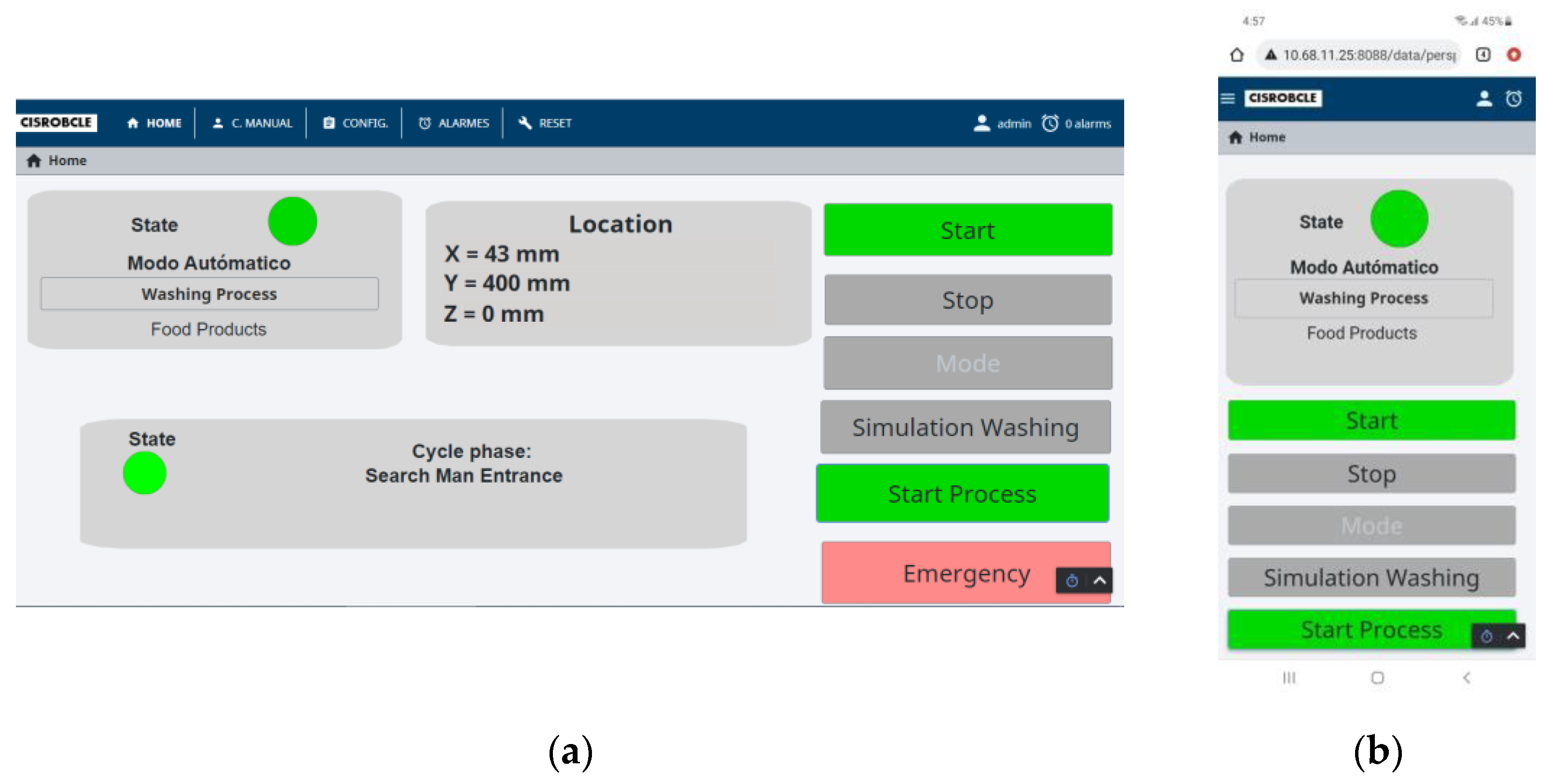
  • Validation of Supervision interfaces
All the functionalities available in the HMI defined in Figure 6 were thoroughly tested, except for those related to alarms, which are discussed later in Topic 3. The tests include the introduction of parameters or the actuation of buttons in the HMI and the validation of the system by comparing the behavior observed in the Digital Twin with the expected behavior. For this validation, commands were issued from different devices, namely an HMI interface connected to the PLC via Ethernet, a smartphone and a computer connected to the SCADA server via the Internet using the HTTP protocol. The tests carried out validated the correct operation of the control and supervision services, as well as their usability in terms of navigation strategy and the visual arrangement of components in each synoptic.
2.
Validation of communication in the SCADA system
To validate the data exchange strategy, wash operations were issued through the supervision interface, and it was verified that the data stored in the database matched the desired wash configurations.
The communication strategy was also validated by means of report generation based on data stored in the database by the SCADA system. To this end, the washes carried out by the DT and the alarms that occurred during its operation were registered in the database. Of the various available reports for this system, a report was automated that shows the various alarms that occurred during the one-week period. The consistency of the stored data and the data in the synoptic alarms and in the reports led to the confirmation of the correctness of the communication between the SCADA system and the database. The functions validated here allow the SCADA system to communicate with the other software present in the organization. It is enough to connect the organizational software with the database adopted for the development of the SCADA system.
3.
Alarm service validation
Verification of alarm signaling was performed by creating faulty or abnormal operating conditions. To this end, three types of situations were selected that exemplify the most common anomalies, specifically:
No manhole detection—A situation where washing cannot proceed due to the necessary conditions not being met. To perform this test, the road tanker was removed from the DT model and a washing task was issued. As a result, the simulated image processing algorithm fails to detect a manhole.
Communication failure—To simulate this event, a failure in the communication between the PLC and the robot X-axis control drive was injected in the DT.
Safety fence crossing—This is a critical situation that leads to an immediate stop of the robot operation. To simulate this, a safety fence crossing event was injected into the DT.
In all tests performed, the anomaly was successfully detected, and the corresponding alarm was triggered and displayed on the HMI interfaces. In addition, following an alarm notification, the HMI presented the operator with instructions to take the necessary actions to resolve the alarm situation.
4.
Validation of user accounts
To validate the security strategy, the three user roles were tested by checking the allowed and blocked actions for each role. For this validation, three fictitious user accounts were first created and associated with different user roles. Each account was then used to access the SCADA system and test all the actions available via the HMI. This test confirmed that only the actions allowed for each role were accessible from the corresponding account and that the security policy was correctly implemented.

5. Conclusions

This paper described the development of the SCADA system for a road tanker washing robot proposed in [18]. The functions assigned to the SCADA system and its architecture characterize it as a fundamental communication center to achieve the intelligent factory concept. The SCADA system allows connecting the entire organization by transferring data between the factory floor and the remaining organizational systems in a bidirectional direction, resulting in added efficiency. The implemented SCADA system integrates a server permanently connected to the Internet, adopts an architecture based on IIoT and allows the development of supervision interfaces that can be accessed remotely via the Internet. The implemented system is also characterized by its high stability and the ability to connect to PLCs from any manufacturer through open protocols widely used in Industry 4.0, such as OPC UA and MQTT. The adoption of new devices to communicate with the robot manipulator can be carried out at any time, thus promoting the M2M concept. Communication with the entire organization is established through a database where the process system and the other organizational software can store and access data. Additionally, the database connection also allows access by big data analysis software to draw conclusions and improve the road tanker washing process. All these functionalities allow easy integration of an FDI system in the SCADA system in the future. To supervise the system, a set of related HMIs were designed in order to target different devices, such as HMI devices, computers, tablets and smartphones, among others. The designed HMIs allow to control and supervise the road tanker washing robot through any devices connected to the Internet, with critical actions being restricted to local devices to guarantee the equipment and the operator’s safety. The SCADA system was connected to a photorealistic DT of the road tanker washing robot to test the process operation and the SCADA system functionalities. To guarantee the correct operation of the SCADA system, a system for detecting specifics faults and alarm and reporting modules have been implemented. In this way, it was possible to verify that all functionalities worked as expected. In addition to testing the entire system, the connection between the DT and the supervision system also allows operators to adapt to the robot’s operating mode, reducing the learning time when the real system is installed.

Author Contributions

Conceptualization, L.V., F.C., F.M.C., M.J.G.C.M. and J.M.F.C.; methodology, L.V., F.C., F.M.C., M.J.G.C.M. and J.M.F.C.; software, L.V., F.C., F.M.C. and M.J.G.C.M.; validation, L.V., F.C., F.M.C., M.J.G.C.M. and G.C.; formal analysis, F.C., F.M.C., M.J.G.C.M., J.M.F.C. and G.C.; investigation, L.V., F.C., F.M.C., M.J.G.C.M. and J.M.F.C.; resources, F.C., J.M.F.C. and G.C.; data curation, L.V., F.C., F.M.C. and M.J.G.C.M.; writing—original draft preparation, L.V., F.C., F.M.C. and M.J.G.C.M.; writing—review and editing, F.C., F.M.C., M.J.G.C.M., J.M.F.C. and G.C.; supervision, F.C., F.M.C., M.J.G.C.M., J.M.F.C. and G.C.; project administration, F.C., J.M.F.C. and G.C.; funding acquisition, F.C., F.M.C., M.J.G.C.M., J.M.F.C. and G.C. All authors have read and agreed to the published version of the manuscript.

Funding

This research was funded by the Program PORTUGAL2020, grant number POCI-01-0247-FEDER-039764.

Institutional Review Board Statement

Not applicable.

Informed Consent Statement

Not applicable.

Data Availability Statement

Data sharing not applicable.

Conflicts of Interest

The authors declare no conflict of interest.

Abbreviations

CPSCyber-Physical System
DoFDegree of Freedom
DTDigital Twin
ERPEnterprise Resource Planning
FDIFault Detection and Isolation
HMIHuman–Machine Interface
HTTPSHypertext Transfer Protocol Secure
IIoTIndustrial Internet of Things
IITIndustrial Information Technology
M2MMachine-to-Machine
MESManufacturing Execution System
MLMachine Learning
MQTTMessage Queuing Telemetry Transport
OPC UAOpen Platform Communications Unified Architecture
PLCProgrammable Logic Controllers
SCADASupervision Control And Data Acquisition
TCP/IPTransmission Control Protocol/Internet Protocol
UPSUninterruptible Power Supply

References

  1. Mozaryn, J.; Bogusz, K.; Juszczynski, S. Development of PLC Based Fault Isolation and Remote IIoT Monitoring of Three Tank System. IFAC-PapersOnLine 2022, 55, 175–180. [Google Scholar] [CrossRef]
  2. Bai, Y.; Wang, J. Fault detection and isolation using relative information for multi-agent systems. ISA Trans. 2021, 116, 182–190. [Google Scholar] [CrossRef] [PubMed]
  3. Zhao, H.; Liu, H.; Hu, W.; Yan, X. Anomaly detection and fault analysis of wind turbine components based on deep learning network. Renew. Energy 2018, 127, 825–834. [Google Scholar] [CrossRef]
  4. Ruppert, T.; Jaskó, S.; Holczinger, T.; Abonyi, J. Enabling technologies for operator 4.0: A survey. Appl. Sci. 2018, 8, 1650. [Google Scholar] [CrossRef] [Green Version]
  5. Khan, A.S.; Khan, A.Q.; Iqbal, N.; Mustafa, G.; Abbasi, M.A.; Mahmood, A. Design of a computationally efficient observer-based distributed fault detection and isolation scheme in second-order networked control systems. ISA Trans. 2022, 128, 229–241. [Google Scholar] [CrossRef] [PubMed]
  6. Pang, Y.; He, Q.; Jiang, G.; Xie, P. Spatio-temporal fusion neural network for multi-class fault diagnosis of wind turbines based on SCADA data. Renew. Energy 2020, 161, 510–524. [Google Scholar] [CrossRef]
  7. Nicholson, A.; Webber, S.; Dyer, S.; Patel, T.; Janicke, H. SCADA security in the light of Cyber-Warfare. Comput. Secur. 2012, 31, 418–436. [Google Scholar] [CrossRef]
  8. Zhou, L.; Su, C.; Li, Z.; Liu, Z.; Hancke, G.P. Automatic fine-grained access control in SCADA by machine learning. Futur. Gener. Comput. Syst. 2019, 93, 548–559. [Google Scholar] [CrossRef]
  9. Panda, A.R.; Mishra, D.; Ratha, H.K. Implementation of SCADA/HMI system for real-time controlling and performance monitoring of SDR based flight termination system. J. Ind. Inf. Integr. 2016, 3, 20–30. [Google Scholar] [CrossRef]
  10. Parrott, A.; Warshaw, L. Industry 4.0 and the Digital Twin; Deloitte University Press: New York, NY, USA, 2017; pp. 1–17. [Google Scholar]
  11. Marr, B. What Is Industry 4.0? Here’s a Super Easy Explanation for Anyone. Forbes, 2 September 2018; pp. 4–7. [Google Scholar]
  12. Liu, J.; Zhang, K. Design and Simulation Debugging of Automobile Connecting Rod Production Line Based on the Digital Twin. Appl. Sci. 2023, 13, 4919. [Google Scholar] [CrossRef]
  13. Zhang, C.; Dong, L.; Wang, Y. Design-Manufacturing-Operation & Maintenance (O&M) Integration of Complex Product Based on Digital Twin. Appl. Sci. 2023, 13, 1052. [Google Scholar] [CrossRef]
  14. Park, J.-S.; Lee, D.-G.; Jimenez, J.A.; Lee, S.-J.; Kim, J.-W. Human-Focused Digital Twin Applications for Occupational Safety and Health in Workplaces: A Brief Survey and Research Directions. Appl. Sci. 2023, 13, 4598. [Google Scholar] [CrossRef]
  15. Wenna, W.; Weili, D.; Changchun, H.; Heng, Z.; Feng, H.; Yao, Y. A digital twin for 3D path planning of large-span curved-arm gantry robot. Robot. Comput.-Integr. Manuf. 2022, 76, 102330. [Google Scholar] [CrossRef]
  16. Wang, X.; Hu, X.; Wan, J. Digital-twin based real-time resource allocation for hull parts picking and processing. J. Intell. Manuf. 2022, 1–20. [Google Scholar] [CrossRef]
  17. Moi, T.; Cibicik, A.; Rølvåg, T. Digital twin based condition monitoring of a knuckle boom crane: An experimental study. Eng. Fail. Anal. 2020, 112, 104517. [Google Scholar] [CrossRef]
  18. Vicente, L.; Lomelino, P.; Carreira, F.; Campos, F.M.; Mendes, M.J.G.C.; Calado, J.M.F. A Photorealistic Digital Twin for a Tank Truck Washing Robotic System. IFIP Adv. Inf. Commun. Technol. 2022, 662, 57–66. [Google Scholar] [CrossRef]
  19. Bitonneau, D.; Moulières-Seban, T.; Dumora, J.; Ly, O.; Thibault, J.F.; Salotti, J.M.; Claverie, B. Design of an industrial human-robot system through participative simulations—Tank cleaning case study. In Proceedings of the IEEE/SICE International Symposium on System Integration (SII), Taipei, Taiwan, 11–14 December 2017; Institute of Electrical and Electronics Engineers Inc.: Piscataway, NJ, USA; pp. 1059–1066. [Google Scholar] [CrossRef] [Green Version]
  20. Park, D.; Han, J.-B.; Yeu, T.; Cho, S.; Kim, S.; Kim, H.; Lee, Y. Development of an Autonomous Cleaning Robot with a Hydraulic Manipulator Arm for the Cleaning of Niche Areas of a Ship Hull. J. Mar. Sci. Eng. 2023, 11, 973. [Google Scholar] [CrossRef]
  21. Vicente, L.; Mendes, M.J.G.C. Projeto De Sistema Scada Para O Novo Paradigma Da Indústria 4.0. Rev. Mecânica Exp. 2022, 35, 1–12. [Google Scholar]
  22. Homay, A.; Chrysoulas, C.; El Boudani, B.; de Sousa, M.; Wollschlaeger, M. A security and authentication layer for SCADA/DCS applications. Microprocess. Microsyst. 2021, 87, 103479. [Google Scholar] [CrossRef]
Figure 1. Kinematic chain of the robot manipulator for washing road tanker.
Applsci 13 08500 g001
Figure 2. Flowchart of the robotic system for truck tank washing.
Applsci 13 08500 g002
Figure 3. DT realistic environment of road tanker washing robot manipulator.
Applsci 13 08500 g003
Figure 4. SCADA system architecture.
Applsci 13 08500 g004
Figure 5. Lifecycle of SCADA software (ISA 101:2015).
Applsci 13 08500 g005
Figure 6. Flowchart of the control and supervision synoptics.
Applsci 13 08500 g006
Figure 7. Supervision application for mobile devices: (a) layout for screens wider than 500 pixels; (b) layout for screens less than 500 pixels wide.
Applsci 13 08500 g007
Figure 8. SCADA system architecture applied to the DT of the road tanker washing robot.
Applsci 13 08500 g008
Table 1. Possible faults/failures in this kind of system and some feasible solutions.
Possible Faults/FailuresSolutions
SensorsRedundant sensors or estimation of measured values
Actuators (Valves)Pipe sections in parallel with redundant valves
Actuators (gantry motors)Alarm, activate safety by stopping the system, call for maintenance
PLC (CPU and/or modules)To use PLC and redundant modules for ATEX systems
CommunicationsTo use redundant communications
Local HMITo use a remote HMI (web based)
Power supplyAlarm and the use of an UPS (Uninterruptible Power Supply)
Pumps (water and detergent)Alarm and to use a redundant pumping system or activate safety, call for maintenance
Physical buttonsTo use redundant buttons and/or call for maintenance
No manhole detectionAlarm and process repetition
Safety fence crossingAlarm and activate safety by stopping the system
Pipe cloggingPipe sections in parallel with redundant valves and call for maintenance
Disclaimer/Publisher’s Note: The statements, opinions and data contained in all publications are solely those of the individual author(s) and contributor(s) and not of MDPI and/or the editor(s). MDPI and/or the editor(s) disclaim responsibility for any injury to people or property resulting from any ideas, methods, instructions or products referred to in the content.

