1. Introduction
The control of a spin-orbit conversion (SOC) in spintronics by managing the spin of electrons is well known (see recent review [
1]). In optics, works on the control of SOC parameters have appeared recently. In [
2], SOC was controlled utilizing excitation of a superposition of vortex laser modes with different spins in thin annular fibers with an empty core, although the first work on SOC in multimode fibers was carried out much earlier [
3]. In [
4], SOC is the cause of the emission of an optical vortex perpendicular to the plane of a ring cavity with defects, along which two whispering gallery modes with different spins (different polarization states) propagate. It was shown in [
5] that SOC can be controlled using q-plates, which transform light with left-handed circular polarization into an optical vortex with right-handed circular polarization. The theoretical aspects of the spin-orbit interaction of light were considered in [
6,
7]. Spin-orbit conversion was observed during light scattering [
8], in a sharp focus [
9], in an anisotropic medium [
10], and upon reflection from an interface of two media [
11]. Spin-orbit interaction was also observed in plasmonics [
12], in nonlinear optics [
13], and in electron optics [
14]. One of the clear manifestations of the spin-orbit light conversion is the optical Hall effect, which appears when the light is reflected from multilayer structures [
15] and when it passes through metasurfaces [
16]. The Hall effect in optics appears as the spatial separation of light beams with different directions of circular polarization (left- and right-handed)—this is the spin Hall effect in optics [
17,
18]. Alternatively, it leads to the spatial separation of light beams with an orbital angular momentum of a different sign—this is the orbital Hall effect [
19,
20]. For further consideration, it is useful to mention works on the optical Hall effect in a sharp focus [
21,
22,
23]. The Hall effect at the focus appears not only due to SOC [
24], but also due to the preservation of the total longitudinal SAM equals to zero during beam propagation [
25]. As was shown in [
26], when a linearly polarized light is sharply focused, the spin is zero in the initial plane and in the focus, but before and after the focus, four local areas appear with nonzero spin of different sign. In [
27], SOC was studied in the light reflected from two crossed metasurfaces. In [
28], the geometric spin Hall effect was considered. SOC in a freely propagating vector cylindrical laser beam with a vortex phase was considered in [
29]. In [
17], the spin-controlled Hall effect was implemented based on a spin-dependent beam splitting into two beams. Sometimes, the Hall effect is understood as a transverse shift of the beam center in the focus because of symmetry violation of a vortex beam or due to the displacement [
30].
In this paper, we consider a spin-orbit conversion of a superposition of two identical optical vortices with circular polarization of different signs and with different amplitudes at a sharp focus. The ratio of the amplitudes of the beams included in this superposition is a parameter that can be varied in order to manage the reduction in spin angular momentum (SAM) and the increase in the orbital angular momentum (OAM) during focusing. The change in the total spin and orbital angular momentum occurs immediately after the light passes through the spherical lens. Further, during propagation in the free space from the lens to the focus, the total spin and orbital angular momentums remain unchanged.
Controlling the spin-orbit conversion in the focus of a spherical lens can be used for changing the rotation velocity of dielectric microparticles. Continuous variation of the parameter (the ratio between the beam amplitudes in the considered superposition) allows changing the SAM in the focus, and changing the rotation velocity of a nonspherical microparticle around its center of mass from zero to maximal. In addition, changing the same parameter allows tuning the OAM in the focus and changing the rotation velocity of a microparticle along a circular path.
Rotation of microparticles either around their own axis or along a circular path is needed in micromachines for contactless driving by light [
31,
32,
33].
2. Projections of the Electric and Magnetic Field Strength Vectors at the Focus
Let us consider that an initial light field with a Jones vector satisfies:
Here (r, φ) are the polar coordinates in the beam section (r = f sinθ, f is the focal length of a spherical lens), n is an integer topological charge of the optical vortex, A(θ) is the real function, the amplitude of the radially symmetric initial light field (1). The radial coordinate r on the spherical front of the converging wave is related to the angle θ between the optical axis and the segment connecting the center of the focus with a point on the spherical front, and 0 < α < 1 is a real number that regulates the contribution to the superposition of light with left- and right-handed circular polarization. It can be seen from (1) that this light field is an axial superposition of two optical vortices with identical topological charges and left- and right-handed circular polarizations. At α = 0 the beam (1) has right-handed circular polarization, and at α = 1 the polarization is linear.
The beam (1) can be considered as a generalized Poincare beam [
21]:
at
p =
q =
n and
In practice, two light modulators are required to form a field (2) with different topological charges
p and
q. Therefore, we restrict our consideration to field (1); when
p =
q, this beam (1) can be formed by only one light modulator. Using the theory [
34], we can write components of the electric and magnetic fields vectors in the sharp focus of the beam (1) as follows:
Functions
Iν,µ in (3) are defined by the following:
where
k = 2π/λ is the wavenumber of the monochromatic light with the wavelength λ,
f is a focal distance of the lens,
θ0 is the maximum tilt angle of the rays to the optical axis, which determines the numerical aperture of the aplanatic lens NA = sin
θ0,
Jμ(
x) is the Bessel function of the first kind and
μ-th order,
z is a longitudinal coordinate, and the focal plane is situated at
z = 0. Function (4) depends on the radial and longitudinal coordinates
Iν,µ(
r,
z). Numbers of Function (4) can be:
ν = 0,1,2;
μ =
n − 2,
n − 1,
n,
n + 1,
n + 2.
Equation (3) indicates that the spherical lens generates additional optical vortices in the converging beam. Besides the initial vortex exp(i
nφ), the field contains four other vortices: exp(i(
n + 2
)φ), exp(i(
n − 2
)φ), exp(i(
n + 1
)φ), and exp(i(
n − 1
)φ). Therefore, the power of the initial optical vortex is partially transferred to these four additional vortices [
35]. Since all the vortices have different amplitudes, left and right circular polarizations can no longer sum up, generating only linear polarization. Elliptic polarization of different sign appears, i.e., the spin Hall effect arises. And vice versa, if initial polarization is right-handed circular, then, due to the additional vortices in Equation (3), the SAM of the beam decreases since some portion of the beam power goes for generating transverse energy rotation, i.e., for generating the longitudinal component of the OAM vector.
It can be supposed that if a light field is focused by spherical lenses with aberrations, the OAM spectrum of the transmitted radiance is even broader and thus even more additional vortices with different topological charges are generated. It is also known that the astigmatic transform, implemented by a cylindrical lens, changes the OAM of an initial vortex-free beam [
36].
Since the amplitudes of the additional optical vortices
are significantly lower than the amplitude of the main optical vortex
[
35], then polarization of the main vortex
(for instance, linear) dominates, whereas polarization of the additional vortices
(for instance, elliptic with different signs) is weaker for any numerical aperture.
3. Density of the Longitudinal Component of the Spin Angular Momentum Vector at the Focus
Using the projections of the electric field strength vectors at the focus (3), we can find the distribution of the longitudinal projection of the spin angular momentum (SAM) at the focus of the field (1). The SAM vector is determined by the relation [
6]:
where
ω is the angular frequency of the monochromatic light. The constant 1/(16πω) is omitted below. Further, we obtain an expression only for the longitudinal projection of the SAM (5), since it coincides with the third component of the Stokes vector and reveals the presence of regions with elliptical polarization in the beam cross section. Taking into account (3), the longitudinal projection of the SAM at the focus of the field (1) can be written as follows:
Equation (6) shows that at
α = 1, field (1) becomes linearly polarized and, at the focus, the longitudinal component of the SAM (6) is equal to the SAM of an optical vortex with linear polarization obtained in [
22]:
It can be seen from (7) that there are four regions at the focus, in two of them the longitudinal SAM is positive at φ = 0 and φ = π, since near the optical axis , and in the other two regions at φ = π/2 and φ = 3π/2 the SAM is negative. On the other circle, where , on the contrary, at φ = π/2 and φ = 3π/2 the SAM is positive, and at φ = 0 and φ = π the SAM is negative. The presence of regions with longitudinal projection of the SAM with different signs at the focus demonstrates the spin Hall effect. Where the SAM is positive, the elliptical polarization vector rotates counterclockwise, and in the regions with the negative longitudinal SAM there is a left-handed elliptical polarization, and the polarization vector rotates clockwise.
There follows another extreme case from Equation (6), when the parameter
α = 0. In this case, the longitudinal SAM at the focus will be equal to the SAM of an optical vortex with right-handed circular polarization obtained in [
23]:
It is seen from (8) that for an optical vortex with right-handed circular polarization at the focus, the SAM varies only along the radius and can have a different sign at different radii. This effect can be called the radial spin Hall effect at the focus. Thus, we have shown that, by varying the parameter α of the initial light field, it is possible to control the characteristics of the spin Hall effect at the focus, i.e., obtain different types of spin distribution at the focus, (7) and (8).
7. Simulation
The simulation is carried out utilizing a Richards–Wolf transformation (RW) [
34]. The numerical aperture of the spherical lens is assumed to be NA = 0.95, that is, the field is limited by an aperture with a radius of 4 µm, and focal length is
f = 1.31 µm. The wavelength λ is 532 nm, the incident wave is a Gaussian beam with the radius σ = 1.33 µm, the size of the initial and output fields is 8 × 8 µm, 400 × 400 points, and
α = 0. The simulation is obtained at a distance from –1 to 1 µm from the focal plane, an apodization is chosen for the case of a spherical lens:
, and a zone plate (ZP),
. In order to avoid dependence on intensity, and also for a more convenient comparison of the results, the OAM and SAM values obtained at distance
z were divided by the total field energy
W. The OAM and SAM, normalized to the field energy,
are shown in
Figure 1.
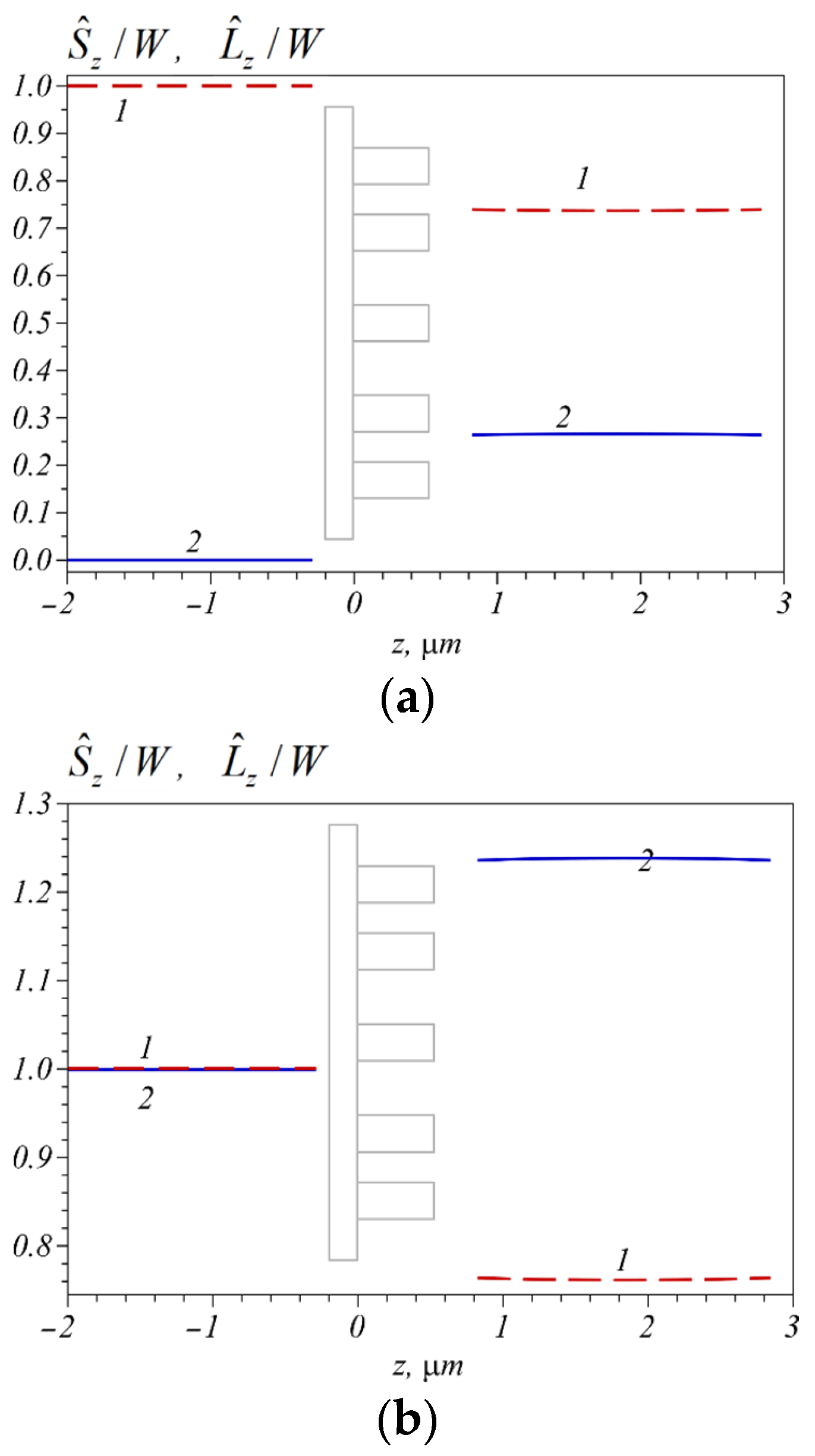
Shown in
Figure 1 is the change in the normalized total longitudinal SAM and OAM for field (1) due to a spin-orbit conversion when the field is focused using a ZP. The numerical aperture of the zone plate is
NA = 0.95. The SAM (curve 1) and OAM (curve 2) are calculated for two cases of the topological charge
n of the initial beam (1): 0 (a) and 1 (b). Shown in
Figure 1, the SAM and OAM values are calculated before and after the ZP, but are not calculated inside it. From
Figure 1a, the SAM before the lens is seen to be equal to 1, while the OAM is equal to 0, since
n = 0. After the lens, the SAM decreases and becomes equal to about 0.76, and the OAM increases up to 0.24. The sum of the SAM and OAM remains unchanged and is equal to 1. Such behavior of the SAM and OAM occurs in accordance with Equations (10), (11), (19) and (21) at
α = 0. If the topological charge of the initial field (1) is 1, then both the SAM and OAM before the lens are equal to 1 (
Figure 1b). Just after the diffractive lens, due to the spin-orbit conversion, the SAM decreases to 0.76, while the OAM increases and becomes equal to 1.24. The sum of them before and after the lens remains unchanged and is equal to 2. This result confirms the correctness of Equation (20).
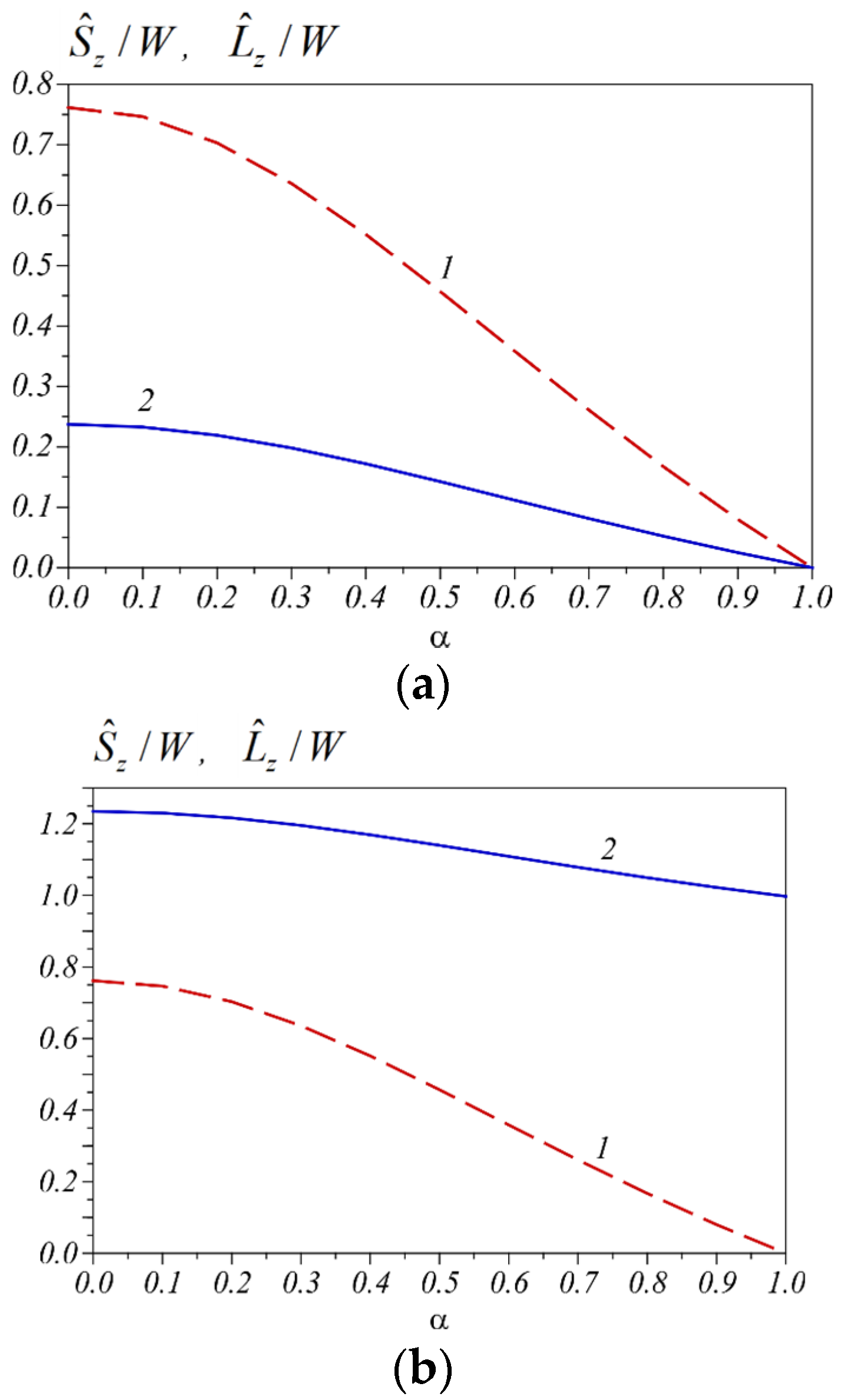
Figure 2 shows the change in the normalized total longitudinal SAM and OAM after the lens depending on
α for the initial light field (1) at
n = 0 (a) and
n = 1 (b). From
Figure 2a, at α = 0 (circular polarization) the SAM and OAM after the lens is seen to be the same as in
Figure 1a. As
α increases, the initial circular polarization becomes elliptical and, therefore, the initial SAM decreases (curve 1) and the part of the SAM that converts into the OAM decreases (curve 2). Additionally, when
α = 1 (linear polarization) both the SAM and OAM after the lens (and before the lens) are equal to zero. The behavior of the SAM and OAM after the lens for an optical vortex (1) with
n = 1 is shown in
Figure 2b. From it the maximum SAM for the initial field (1) with circular polarization (
α = 0) is seen to be equal to 0.76. Furthermore, the minimal value of the SAM is zero, for the field with linear polarization (
α = 1). In this case, the maximal OAM is equal to 1.24 when
α = 0, and the minimal OAM is equal to 1 at
α = 1. Such behavior of the SAM and OAM after the lens is described by Equations (10), (19) and (20).
Shown in
Figure 3 are the normalized total longitudinal SAM and OAM as functions of a numerical aperture and focal distance for the initial field (1) at
n = 1,
α = 0.5. From
Figure 3 the sum of the SAM and OAM is seen to remain unchanged and be equal to 1.6. This follows from Equation (20), since
. For the numerical aperture of 0.95 and α = 0.5, from
Figure 2a, the SAM after the lens is seen to be approximately 0.5, whereas the initial SAM is equal to 0.6. That is, because of the spin-orbit conversion, only a small part of the SAM (about 0.1) transferred into the OAM. From
Figure 3, the minimum value of the SAM after the lens is seen to be approximately 0.35 for a numerical aperture close to 1. Therefore, the maximum value of 0.25 is converted from the SAM into the OAM. As the numerical aperture decreases, curve 1 in
Figure 3 tends to a value of 0.6, i.e., to the initial SAM value before the lens. That is, it follows from
Figure 3 that the effect of the spin-orbit conversion in a spherical lens with a numerical aperture less than 0.7 can be neglected.
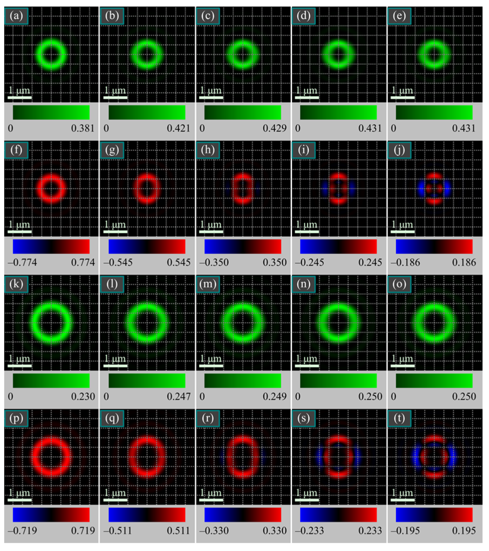
Shown in
Figure 4 are the intensity
I (first and third rows) and the longitudinal SAM
Sz (second and fourth rows) for different values of the parameter
α: 0 (first column), 0.5 (second column), 0.75 (third column), 0.9 (fourth column), and 1 (fifth column). The topological charges are
n = 3 (first and second rows),
n = 5 (third and fourth rows).
It is seen from
Figure 4 that, according to the theory (6)–(8), the distribution of the longitudinal SAM is radially symmetric (red ring in the first and second columns) in the focus of the field (1) for a small parameter
α. As the parameter
α increases, the red ring in
Figure 4 becomes an ellipse (second and third column), and when
α is close to 1, one part of the ring remains red, and another part becomes blue (fourth and fifth columns). That is, areas with a negative SAM appear in the focus and the spin Hall effect appears (separation of left- and right-handed elliptical polarizations). When the parameter
α increases from 0 to1, the intensity (green rings in
Figure 4) gradually transforms from a round ring (at initial circular polarization) into an elliptical one (at initial linear polarization), which is elongated along the horizontal axis
x. However, since the term with
exceeds the term with cos(2φ) in Equation (12) for the intensity distribution, the intensity ellipticity in
Figure 4 is almost invisible at α = 1. With an increase in the topological charge of the optical vortex (1) from
n = 3 to
n = 5, the diameter of the light ring shown in
Figure 4 increases. This follows from the intensity Equation (12).
8. Conclusions
In this paper, we study a spin-orbit conversion in a spherical lens with a high numerical aperture. Utilizing the Richards–Wolf theory [
34], analytical formulas are obtained for the density of the longitudinal SAM and OAM projections at the focus of the lens for the initial light field (1). The amplitude of the field depends on the real parameter
α. The initial light field (1) is an axial superposition of two optical vortices with the same topological charge
n and right- and left-handed circular polarizations. Amplitudes of both beams in the superposition are different. The parameter α is the ratio of the amplitudes of the beams. In this work, analytical formulas are obtained for the total longitudinal projections of the SAM and OAM at the focus of the field (1). It follows from the Formulas (10), (11) and (19), (21) that when passing through a spherical lens (or a diffractive lens), the total SAM decreases due to a spin-orbit conversion, while the OAM increases by the same amount. In this case, the sum of the SAM and OAM remains unchanged during focusing (Equation (20)). Simulations are also carried out using the Debye and Richards–Wolf integrals [
34]. When the light field (1) propagates before a spherical lens, the total SAM and OAM are shown to remain unchanged separately. After passing through the lens, the total SAM decreases, and the total OAM increases by the same value. When propagating after the lens, the total SAM and OAM remain unchanged separately too. The sum of the SAM and OAM before the lens and after it does not change (
Figure 1). When the parameter
α increases from 0 to 1, the spin-orbit conversion in a spherical lens is shown numerically to decrease from its maximum value to zero. With a numerical aperture of 0.95 and with
α = 0, the initial normalized total longitudinal SAM is equal to 1 before the spherical lens, and equal to 0.76 after it. That is, only a quarter of the SAM transferred to the OAM (
Figure 2). The maximum spin-orbit effect in a spherical lens is shown numerically to occur at a numerical aperture close to 1 (
Figure 3). For smaller aperture values, the effect decreases. It is shown that, at a numerical aperture less than 0.7, the spin-orbit conversion can be neglected, since the total SAM remains almost unchanged when light passes through a spherical lens. Theoretically (Equation (7)) and numerically (
Figure 4) it is shown that there is a spin Hall effect at the focus of the light field (1). This effect leads to appearance of regions with elliptical polarizations with different signs in the sharp focus. That is, at the focus, light with left- and right-handed elliptical polarizations is separated in space. In this case, in the initial plane only linearly polarized light is present (
Figure 4). By changing the parameter
α the spin Hall effect at the focus can be controlled. When
α = 0, the initial field is circularly polarized, and the Hall effect is minimal at the focus. When
α = 1, there is a linearly polarized initial field, and the Hall effect achieve its maximum at the focus.
Measuring the magnitude of the spin-orbital conversion effect in the sharp focus of a microobjective with a high numerical aperture requires measuring the third component of the Stokes vector averaged over the beam transverse section. The value of this quantity gives the full longitudinal SAM component. In addition, the third component of the Stokes vector can be measured immediately in the microobjective’s exit pupil with a diameter of several millimeters, rather than in the focus itself whose size can be less than a micron.
The effects of spin-orbit conversion in a spherical lens and the spin Hall effect at the focus considered in this work can be used to control the rotation of microparticles [
38,
39].


