Article

Study on Characteristics of Tool Wear and Breakage of Ultrasonic Cutting Nomex Honeycomb Core with the Disc Cutter

State Key Laboratory of High-Performance Precision Manufacturing, Dalian University of Technology, Dalian 116024, China
*
Author to whom correspondence should be addressed.
Appl. Sci. 2023, 13(14), 8168; https://doi.org/10.3390/app13148168
Submission received: 3 April 2023 / Revised: 24 June 2023 / Accepted: 6 July 2023 / Published: 13 July 2023
(This article belongs to the Section Mechanical Engineering)

Abstract

:
Ultrasonic cutting is an advanced technology for processing Nomex honeycomb materials. The disc cutter is one of the most commonly used tools, whose wear and breakage state have an important impact on the honeycomb material machining process. Currently, the disc cutter lacks systematic characterization methods, and its tool wear laws are not yet clear. This paper conducts a wear experiment of the disc cutter in an ultrasonic cutting Nomex honeycomb core and proposes the attributes of cutting edge rounding (CER), flank wear VB, diameter reduction, and cutting edge breakage width to characterize the tool wear and breakage forms quantitatively. Moreover, the tool wear and breakage forms of the disc cutter are categorized, and the variation laws of the disc cutter wear and breakage characteristics are studied. The experimental study reveals that the wear forms of the disc cutter are mainly cutting edge dulling and flank wear. The CER and flank wear VB increase with increasing cutting length, and the wear mechanism is mainly abrasive wear. The breakage forms are mainly chipping and cracking breakage. The diameter reduction changed slowly, and the cutting edge breakage width tended to increase. The surface quality of the honeycomb gradually deteriorates with the increase of tool wear and breakage. The experimental results are important to study the tool wear mechanism of ultrasonic cutting of the Nomex honeycomb core with the disc cutter as well as tool design and manufacture.

1. Introduction

Nomex honeycomb sandwich structures have been widely used in the aerospace and rail transportation fields because of their excellent characteristics of high specific strength and stiffness, superior impact resistance, fatigue resistance, wave transmission, and thermal insulation [1,2,3]. The Nomex sandwich structures are manufactured by bonding honeycomb cores and the upper and lower skins together, exhibiting diverse shapes, such as the application of the flaps, elevators, rudders, nacelles, and wing-body fairings of large aircraft [4,5,6]. The bonding surfaces of honeycomb cores need to be processed into specific geometric shapes according to the assembly requirements. Nomex honeycomb cores are typical difficult-to-process materials due to the characteristics of thin-walled porosity, weak stiffness, and anisotropy. The traditional processing method of high-speed milling is prone to generating defects such as tearing and burr, in which processing quality is not easily guaranteed [7]. Currently, ultrasonic cutting has become the advanced processing method of Nomex honeycomb cores, thanks to its significant performance of reducing cutting force, improving surface quality, and decreasing dust harm [8,9,10].
During ultrasonic cutting of Nomex honeycomb core, the disc cutter is usually used as the precision processing tool, deciding the ultimate bonding surface quality. In recent years, scholars have carried out related research in the ultrasonic cutting disc cutter machining process. Meng et al. [11] analyzed the factors influencing the cutting force during the ultrasonic cutting of the Nomex honeycomb core with the disc cutter and carried out an ultrasonic cutting experiment of the Nomex honeycomb core to obtain the influence laws of disc cutter machining parameters on cutting force and surface quality. Ahmad et al. [12,13] designed a new ultrasonic circular saw blade cutter based on the original structure of the disc cutter and studied the variation law of cutting force and surface quality of the circular saw blade cutter and disc cutter under different process parameters. The results showed that the ultrasonic cutting of the Nomex honeycomb core by the circular saw blade cutter and disc cutter had good results. Moreover, Sun et al. [14,15] investigated the cutting force and the surface quality of aluminum honeycomb during ultrasonic cutting with a disc cutter utilizing finite element simulation and experimental validation, showing that ultrasonic cutting using a disc cutter can achieve high quality and high efficiency in the machining of aluminum honeycomb.
Due to the long machining path caused by the large size of honeycomb workpieces in actual machining, the disc cutter inevitably generates tool wear and breakage, thus affecting the machining accuracy, surface quality, and machining efficiency of honeycomb materials. So, it is critical to research disc cutter tool wear and breakage. On the research methods of tool wear and breakage in processing honeycomb material, Guo et al. [16] used an optical microscope to study the chipping law during ultrasonic cutting of wave-absorbing honeycomb material with the disc cutter and showed that the number of chipping edges and notches increased with the increase in cutting length. David et al. [17] conducted tool wear analysis of the entire high-speed milling of the Nomex honeycomb core using a high-speed camera and clearly observed that the tool underwent a morphological change process such as significant wear of the lowest teeth on the tool and missing multiple cutting edges. Jaafar et al. [18] studied the state of tool wear and breakage for machining Nomex honeycomb core material using a scanning electron microscope, and the adhesion of phenolic resin was clearly observed by the scanning electron microscope. The results indicated that the tool wear and breakage were mainly divided into the adhesion of the phenolic resin to the tool, flank wear, and loss of edge sharpness. In terms of tool wear and breakage characteristics of ultrasonic cutting of honeycomb materials by disc cutter, Zha et al. [19] found that with the increase in cutting length, wear morphological characteristics such as small tears, large tears, edge chipping, and scratches appeared in the disc cutter and proposed a radial difference calculation (RDC) method for quantitative characterization of tool wear of the disc cutter. The results showed that ultrasonic cutting with the disc cutter produced less tool wear than conventional cutting.
In summary, for ultrasonic cutting of the Nomex honeycomb core, the study of disc cutter wear and breakage is relatively preliminary. Thus, the tool wear form of the disc cutter for ultrasonic cutting the Nomex honeycomb core and its evolution laws need to be studied. In this study, by carrying out an ultrasonic cutting of Nomex honeycomb core tool wear experiment, the surface morphologies before and after tool wear and breakage during ultrasonic cutting of Nomex honeycomb cores with a disc cutter are observed. The morphological characteristics of ultrasonic cutting disc cutter tool wear and breakage are analyzed. In addition, the characterization methods of disc cutter tool wear and breakage are proposed, and the evolution laws of disc cutter tool wear and breakage characteristics are studied. The methods and observations used in this characteristics study can be extended for tool wear studies under different process parameters.

2. Experimental Conditions and Methods

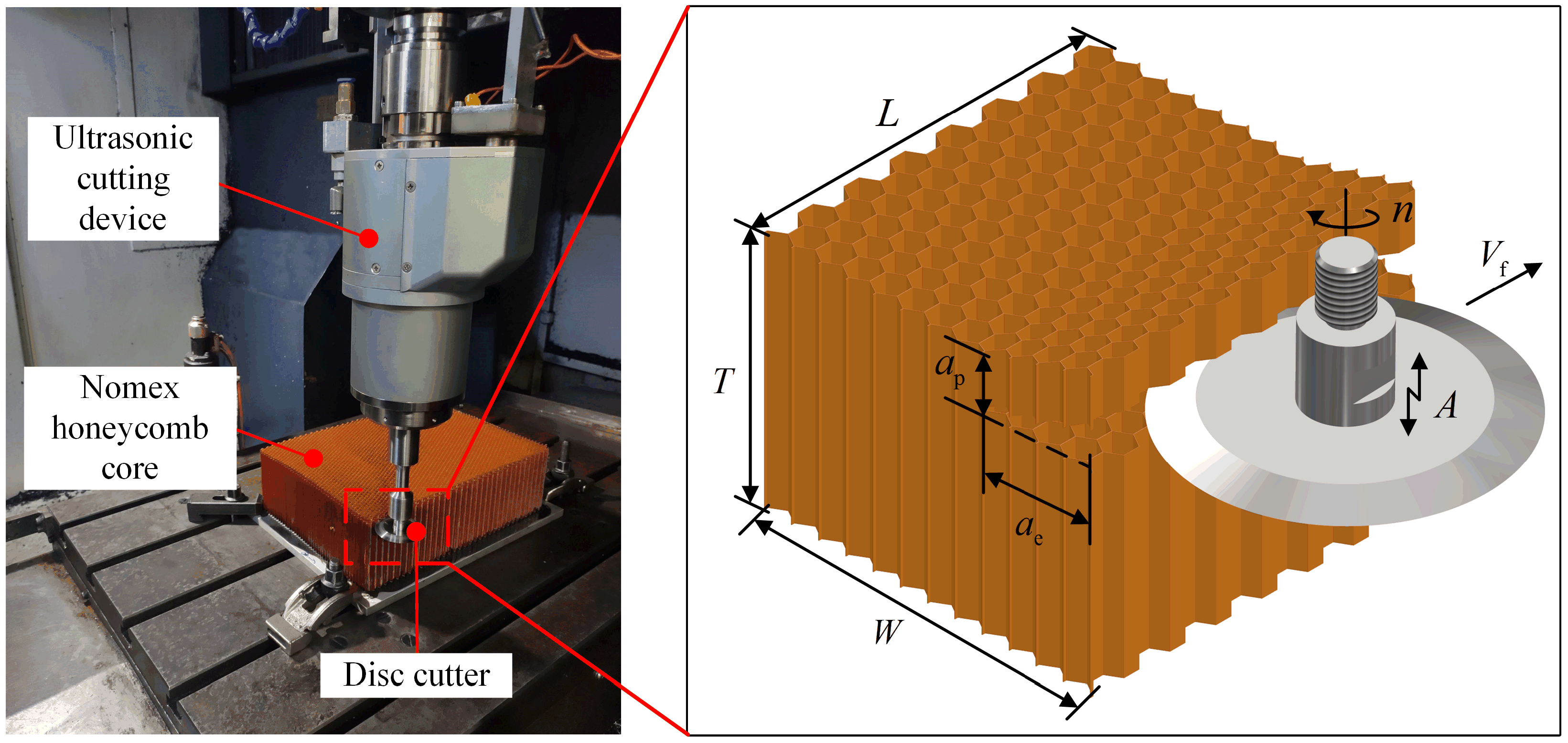
2.1. Experimental Setups and Procedure

The honeycomb core experimental specimen brand is NH-1-2.75-32, and its cell wall length and density are 2.75 mm and 32 kg/m3, respectively. The dimensions of the experiment specimen are 310 × 220 × 100 mm (L × W × T). The experiment tool is a disc cutter, and its physical drawing and schematic diagram are shown in Figure 1. The disc cutter consists of the thread section, connection section, and cutter section. Among them, the cutter section is used to realize the cutting process between the tool and Nomex honeycomb core [20], and the disc cutter material and tool geometry parameters are shown in Table 1. The hardness of the disc cutter is 63 HRC. Therefore, a multi-position observation and study of the surface morphology of the disc cutter was performed using an ultra-depth microscope (VHX-600E, KEYENCE) and scanning electron microscope (SU5000, HITACHI).
The ultrasonic cutting wear experiment device and cutting schematic diagram of the disc cutter are shown in Figure 2. The experiment platform for ultrasonic cutting Nomex honeycomb core processing of disc cutter adopted a three-axis CNC machine tool, and the ultrasonic cutting system adopted the self-developed ultrasonic system. Furthermore, the experiment platform and ultrasonic system were integrated to meet the experiment’s requirements. The ultrasonic amplitude was measured using the point laser measurement system (LK-G5000, KEYENCE) before the experiment started, and the ultrasonic power supply parameters corresponding to the ultrasonic amplitude were well calibrated. The ultrasonic amplitude measurement and specific parameters of the experiment are shown in Figure 3 and Table 2.
The specific procedure for the tool wear experiment is as follows: first of all, the initial diameter of the new disc cutter was measured, and the cutting edge and flank face initial morphologies of the disc cutter were observed. Subsequently, the tool wear experiment was carried out, and the different positions of the worn disc cutter and the machined surface morphologies of the honeycomb core were observed and measured. Afterward, the next round of tool wear experiment was carried out, and so the process cycles four rounds to end the experiment. During the experiment, for each round of the tool wear process, the cutting depth was 1 mm, and five layers were continuously cut. At the 5th layer, ultrasonic cutting was still performed, but the ultrasonic power was turned off for conventional cutting at the last feed cut, which was used to observe the surface morphology of the honeycomb after conventional cutting. Thus, the cutting length of each round was 23.25 m, and the total cutting length of the experiment was 93.00 m. After the four rounds of the tool wear cycle experiment, the overall observation and analysis of tool wear and breakage characterization and honeycomb core surface quality were carried out.

2.2. Evaluation Methods of Tool Wear and Breakage

The dullness criteria and service life of ultrasonic cutting tool are the keys to the stable operation of ultrasonic cutting tool, and the characterization of disc cutter tool wear and breakage is a prerequisite for the study of tool dullness criteria and service life [21]. In this paper, the morphological characteristics of disc cutter tool wear and breakage are characterized by selecting cutting edge rounding (CER), flank wear (VB), diameter reduction, and cutting edge breakage width.

2.2.1. Cutting Edge Rounding (CER)

The CER is a parametric representation of the degree of cutting edge passivation and has been increasingly recognized and used by scholars [22,23,24]. The ultrasonic tool disc cutter reciprocates cutting and friction with honeycomb material under high-frequency vibration, and its degree of passivation has an important influence on the molding quality of the honeycomb material. Therefore, the CER parameter is chosen to characterize the cutting edge wear condition of the disc cutter. The CER algorithm used in this paper referred to the method proposed by Wyen et al. [25], which used an iterative method to determine the fitting boundary and region of the front and rear tool surfaces and finally solved the CER fitting for the selected area. In this study, the overall calculation process is shown in the flow chart of Figure 4. Due to the large diameter and small wedge angle of the disc cutter, the observation depth was large, and it was difficult to measure the cutting edge parameters directly using the measuring instrument. It was also impossible to extract the cutting edge data from the disc cutter, so the indentation method was used to measure the cutting edge [26]. Firstly, the disc cutter after the cutting process was embossed on the soft metallic lead foil, and then the built-in software of the ultra-depth microscope was used to obtain the cross-sectional contour, and finally the CER was calculated by fitting the two-dimensional curve profile with MATLAB. Figure 5 shows the two-dimensional profile curves of the indentation at different positions.

2.2.2. Flank Wear VB

The flank wear VB is the common wear form of disc cutter ultrasonic cutting Nomex honeycomb core, and this paper selects the flank wear VB, by which the flank wear condition of disc cutter is characterized. The specially designed fixture for disc cutter inspection and flank wear measurement is shown in Figure 6. During the cutting process, multiple areas of the flank face before and after the cutting process were tracked and observed using an ultra-depth microscope. In addition, considering that the cutting edge of the disc cutter itself was worn during the cutting process and that the measurement direction was along the radial direction of the disc cutter, flank wear VB was measured [27,28] and calculated to achieve a quantitative representation of flank wear.

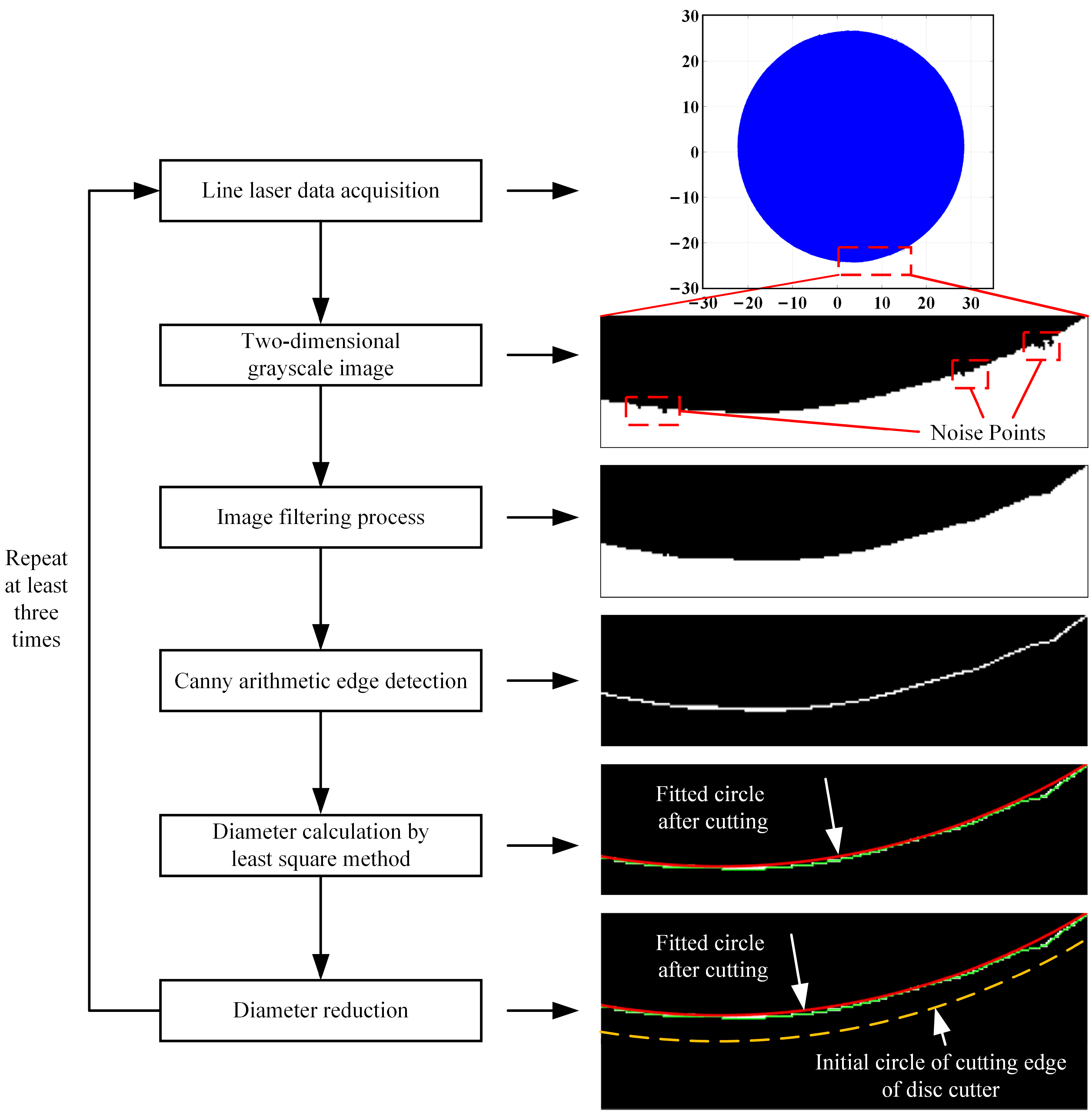
2.2.3. Diameter Reduction

The diameter reduction of the disc cutter is a parameter to measure the overall degree of breakage of the disc cutter. In the cutting process, damage conditions such as micro-chipping and chipping at multiple positions of the cutting edge will have a direct impact on the change in tool diameter. In this paper, the diameter reduction is selected as the parameter to characterize the diameter change of the disc cutter after overall damage. The flowchart for calculating the diameter reduction of the disc cutter is shown in Figure 7. Firstly, the point cloud scanning technology was used to scan the contour of the flank face before and after the wear of the disc cutter, and the specific point cloud scanning results are shown in Figure 8. Then, MATLAB was used to convert the line laser three-dimensional point cloud data into a two-dimensional grayscale image. The conversion process would inevitably produce noise points, as shown in the red box in Figure 7, so image filtering and denoising were performed under the premise of considering the calculation accuracy. After that, the edge detection of the disc cutter’s cutting edge was performed. The classical edge extraction operator Canny operator edge detection was chosen for image processing because the detection technique using image edge features was very mature and had high accuracy, and the processing results had good edge detection continuity and high clarity [29]. Finally, the least squares method was used to calculate the diameter of the disc cutter for the cutting edge. In the calculation result, the green line represented the disc cutter edge acquisition trajectory, and the red line represented the fitted circle after the cutting process as determined by the least squares method. The diameter reduction was the difference between the initial diameter of the disc cutter and the calculated diameter after this cutting process was completed.

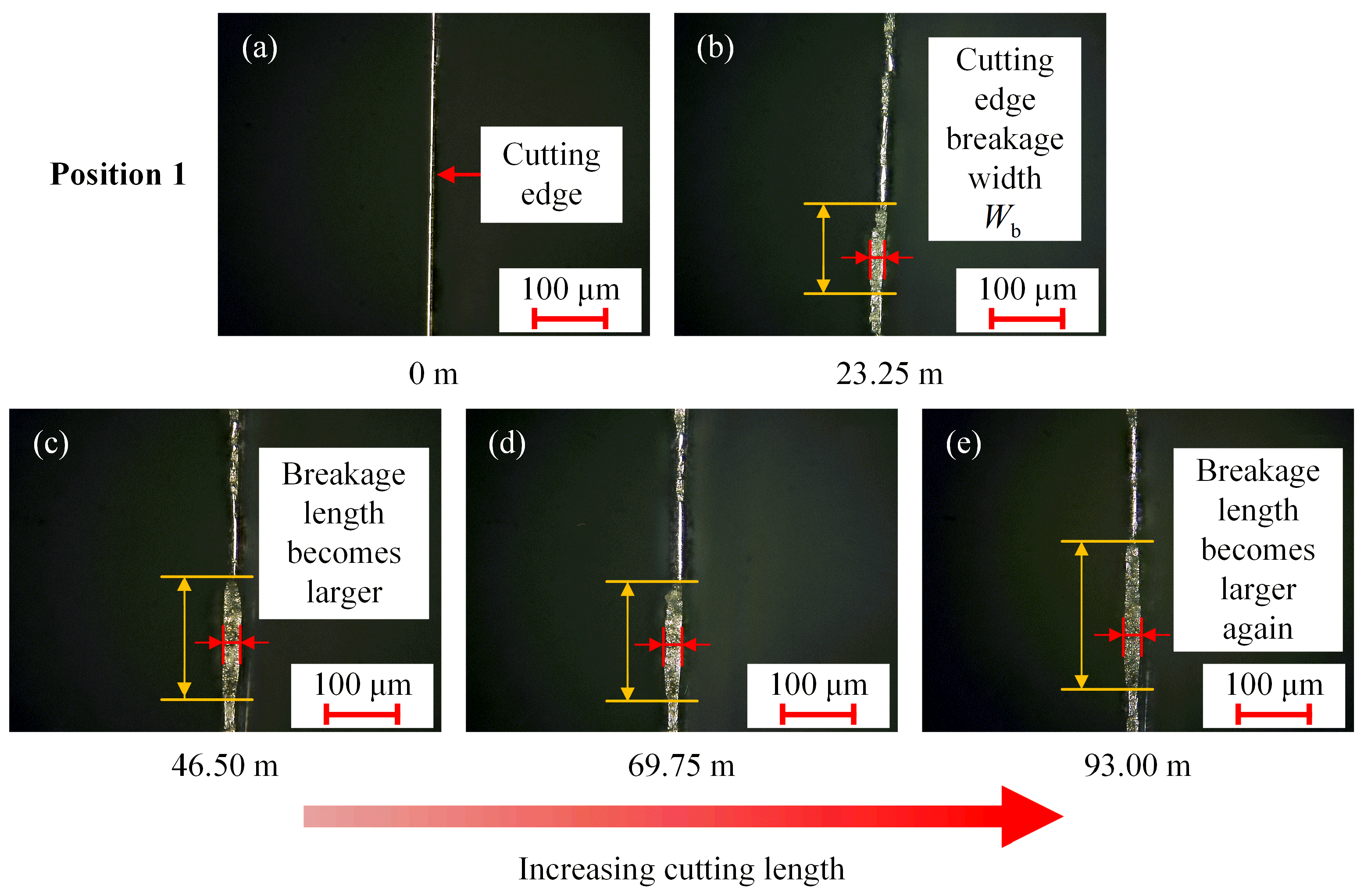
2.2.4. Cutting Edge Breakage Width

In the ultrasonic cutting process, some parts of the cutting edge of the disc cutter are often broken, and a larger chipping may even lead to a significant loss of the cutting edge there. In this study, the parameter of cutting edge breakage width is used to characterize the degree of chipped breakage of the disc cutter. During the wear experiment, multiple areas of the cutting edge of the disc cutter were tracked and measured using an ultra-depth microscope, and the cutting edge breakage width was measured as shown in Figure 9, where the cutting edge breakage width was denoted by Wb.

3. Results and Analysis

3.1. Disc Cutter Wear Analysis

3.1.1. Morphological Characteristics of Tool Wear

After the experiment, a comparison of the wear morphology characteristics of the disc cutter is shown in Table 3. The cutting edge morphologies are shown in Table 3a,b. Table 3a shows the cutting edge morphology before cutting, and the cutting edge was sharp. When the longitudinal high-frequency vibration of the cutting edge was cutting the honeycomb core material, the cutting edge of the disc cutter was continuously worn to make the cutting edge gradually blunt, as shown in Table 3b. Table 3c,d show the morphologies of the flank face: there was no wear on the flank face before cutting, as shown in Table 3c. The wear on the flank face after cutting was mainly concentrated near the cutting edge, as shown in Table 3d. The reason for this is that the positive clearance angle of the disc cutter makes the part away from the cutting edge have little contact with the honeycomb core processing surface during the cutting process, and thus no wear is generated. However, the flank face of the disc cutter near the cutting edge is in constant high-frequency contact and friction with the aramid fiber and phenolic resin layer in the honeycomb material and interacts with the honeycomb core material to produce wear and breakage, thus producing flank wear.

3.1.2. Cutting Edge Rounding (CER)

The CER was measured at the end of each round of wear experiments, and significant wear was observed on the overall cutting edge of the disc cutter; i.e., the cutting edge became blunt. In order to avoid the deviation of the experimental results, measurement and counting of only the cutting edges where wear occurred, cutting edge wear morphologies, and the variation of CER are shown in Figure 10 and Figure 11. During the cutting process, the rake face and flank face of the cutting edge on both sides were continuously worn, and the CER became larger and tended to increase. When the cutting length was 23.25 m, the disc cutter was in the initial wear stage, and the cutting edge of the disc cutter was sharp. The disc cutter was in contact with the honeycomb surface in a small area, and the strong, tough aramid fiber and the brittle phenolic resin layer had more contact pressure on the disc cutter along the radial direction, which made the cutting edge of the disc cutter wear faster and the CER increase from 3.54 μm to 6.74 μm. In addition, under the action of longitudinal high-frequency ultrasonic vibration, the cutting edge was constantly subjected to periodic impact stress, which made the cutting edge wear and even break. Especially in the moment of contact with the honeycomb hole grid before each cut of the disc cutter, high-frequency ultrasonic vibration made the cutting edge of the disc cutter constantly scrape on the honeycomb wall, which made the cutting edge of the disc cutter constantly wear. As the cutting length increased from 46.50 m to 93.00 m, the CER increased more slowly from 6.74 μm to 8.26 μm.

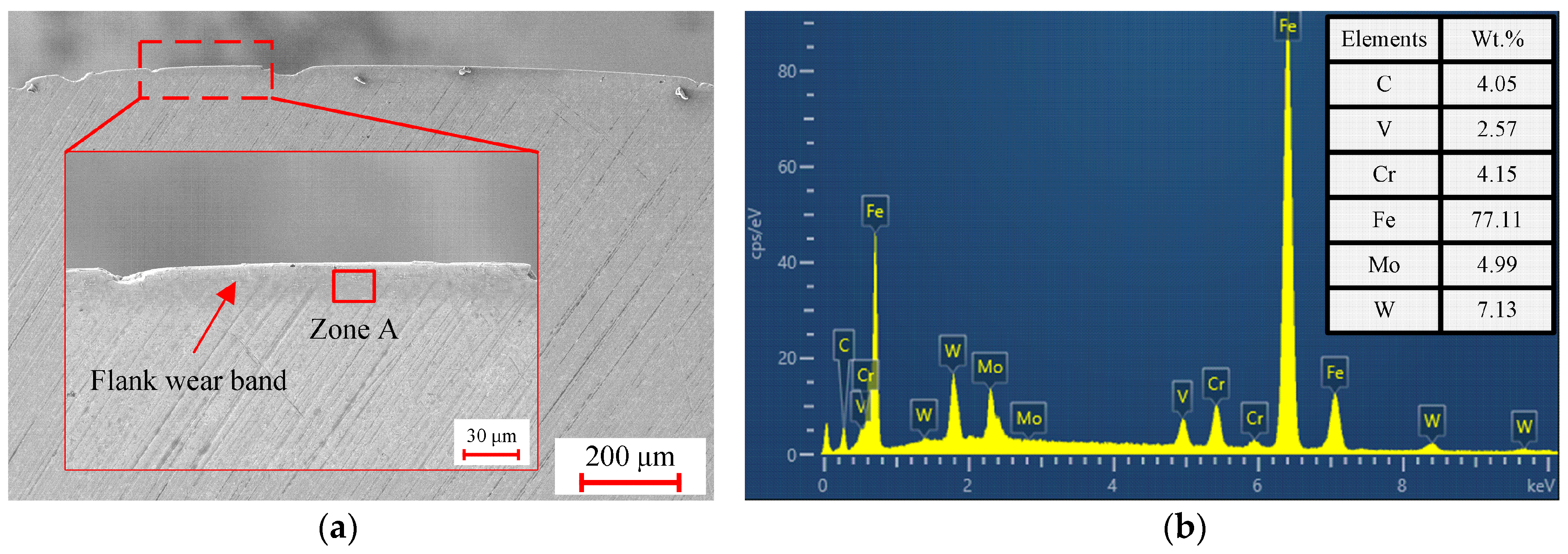
3.1.3. Flank Wear VB

The overall wear of the disc cutter was observed, and the overall wear of the flank showed uneven wear. Figure 12 shows the wear morphologies of disc cutter at the same cutting position under different cutting lengths, and it can be seen that the flank wear is mainly for the wear ribbons and flank wear bands. Positions 1 and 2 show trace wear phenomena on the flank face during ultrasonic cutting, producing a wear ribbon at the cutting edge. Furthermore, scratches caused by high-strength aramid fiber, phenolic resin, and other materials appeared to varying degrees on the disc cutter’s flank face. Moreover, due to the presence of the positive clearance angle of the disc cutter, at a cutting length of 93.00 m, the scratches near the cutting edge were gradually covered by friction as the cutting length increased. The flank wear band was clearly visible in position 3. This is because the honeycomb core has rebound characteristics. During the cutting process, the honeycomb core was deformed elastically by the extrusion pressure of the cutting edge and the friction between the rake face and flank face [30], and the high-strength aramid fiber repeatedly rubbed the flank face during the high-speed rotation of the disc cutter, resulting in a flank wear band. Figure 13 and Figure 14 show the results of the SEM observation and the variation of flank wear VB with cutting length at position 3, respectively. It can be clearly seen from Figure 13 that the wear band marked on the tool’s flank face and the transverse scratches near the cutting edge also indicate abrasive wear of the disc cutter, while EDS analysis also shows that no oxidative wear has occurred on the flank face of the disc cutter. When the cutting length was increased from 23.25 m to 93.00 m, the flank wear VB did not change significantly. Also, a new micro-chipping occurred in the middle of the wear band area when the cutting length was 93.00 m. In this process, the wear was relatively uniform and basically in the normal wear stage.

3.2. Disc Cutter Breakage Analysis

3.2.1. Morphological Characteristics of Tool Breakage

The breakage morphologies of the disc cutter are shown in Figure 15. Figure 15a,b show the chipping and cracking breakage, respectively, and it can be found that the broken parts of the disc cutter are mainly concentrated at the edge of the cutting edge. Chipping is the most common morphology of tool breakage during ultrasonic cutting of honeycomb core with a disc cutter, and with the increase in cutting length, the chipping edge will expand to form a continuous chipping edge. Especially when cutting honeycomb material with high density, continuous chipping and cracking breakage will occur on the flank face of the disc cutter. Analysis of its cause is that the higher density of aramid paper honeycomb as a whole presents high-hardness and flexibility [31,32], so the disc cutter’s cutting edge in the rotary cutting process, when encountering a hard, brittle phenolic resin layer, will lead to chipping and even cracking breakage.

3.2.2. Diameter Reduction

The diameter reduction of the disc cutter after each round of tool wear experiments was calculated using the above characterization parameters. The result is shown in Figure 16, and it is found that the diameter reduction tends to increase gradually. When the cutting length was 23.25 m, as the cutting edge of the tool had already appeared chipping at this time, as shown in Figure 17b, the diameter reduction increased from 0 to 74.2 μm significantly, which was at the initial tool wear stage. As the cutting length increased, the cutting edge area continued to wear and even break during the high-frequency vibration cutting process, which further reduced the edge strength and even showed chipping and continuous chipping, thus showing a band distribution and resulting in a gradual increase in the diameter reduction of the disc cutter. It can be clearly seen from Figure 16 that when the cutting length changes from 46.50 m to 93.00 m, the chipping at a certain position of the disc cutter gradually started to expand, and a new chipping appeared nearby, as shown in Figure 17c, and then a continuous chipping was formed, as shown in Figure 17d. When the cutting length was 93.00 m, the chipping of the disc cutter did not change much at this time, as shown in Figure 17e, and the diameter reduction was 159.4 μm, which indicated that the disc cutter was in the normal wear stage at this time and that the cutting process was stable and the diameter reduction increased slowly. Using SEM observations at 93.00 m for this position, as shown in Figure 18, it was found that some cracks appeared near the chipping as well as slightly inward, and the direction of the cracks was perpendicular to the radial direction of the disc cutter. It is presumed that this may be because the chipping position of the tool is more fragile and that under ultrasonic high-frequency vibration, the flank scratches caused by abrasive wear gradually expand to form cracks, which then continue to expand until finally fractured to form a new chipping.

3.2.3. Cutting Edge Breakage Width

The all-round observation of the cutting edge of the disc cutter revealed that the overall broken parts were randomly distributed, with the majority of micro-chipping. With the increase in the cutting length, the number of chippings also increased, and the cutting edge breakage width was increasing. By taking the morphological images of the same area at the cutting edge breakage after different cutting lengths, the changes in the cutting edge breakage in this area during the whole wear experiment were obtained. Figure 19, Figure 20 and Figure 21 show the breakage morphologies of the disc cutter at the same cutting position under different cutting lengths and the cutting edge breakage width variation curves, respectively. From Figure 19, Figure 20 and Figure 21, it can be seen that when the cutting length was 23.25 m, the cutting edge positions 1 and 2 were both chipped and broken, and the degree of chipping in position 2 was somewhat greater. At this time, when the disc cutter under the action of ultrasonic vibration failed to form an effective cut on the honeycomb core, with only continuously intermittent contact and longitudinal friction, it made the breakage width and breakage length of the cutting edge became larger. Examples include the change in breakage width from position 1 (b) to (e) and the change in breakage length indicated by the yellow arrow, as well as the change in breakage width from position 2 (b) to (d). When the cutting length increased from 69.75 m to 93.00 m, the breakage depth also increased; i.e., the breakage depth increased to a certain value; a larger degree of breakage occurred; and the position failed to make contact with the honeycomb core during cutting, or the degree of friction was small, making the breakage width change slowly. At this time, the disc cutter was in the normal wear stage, as shown in position 1 (d) to (e) and position 2 (d) to (e).

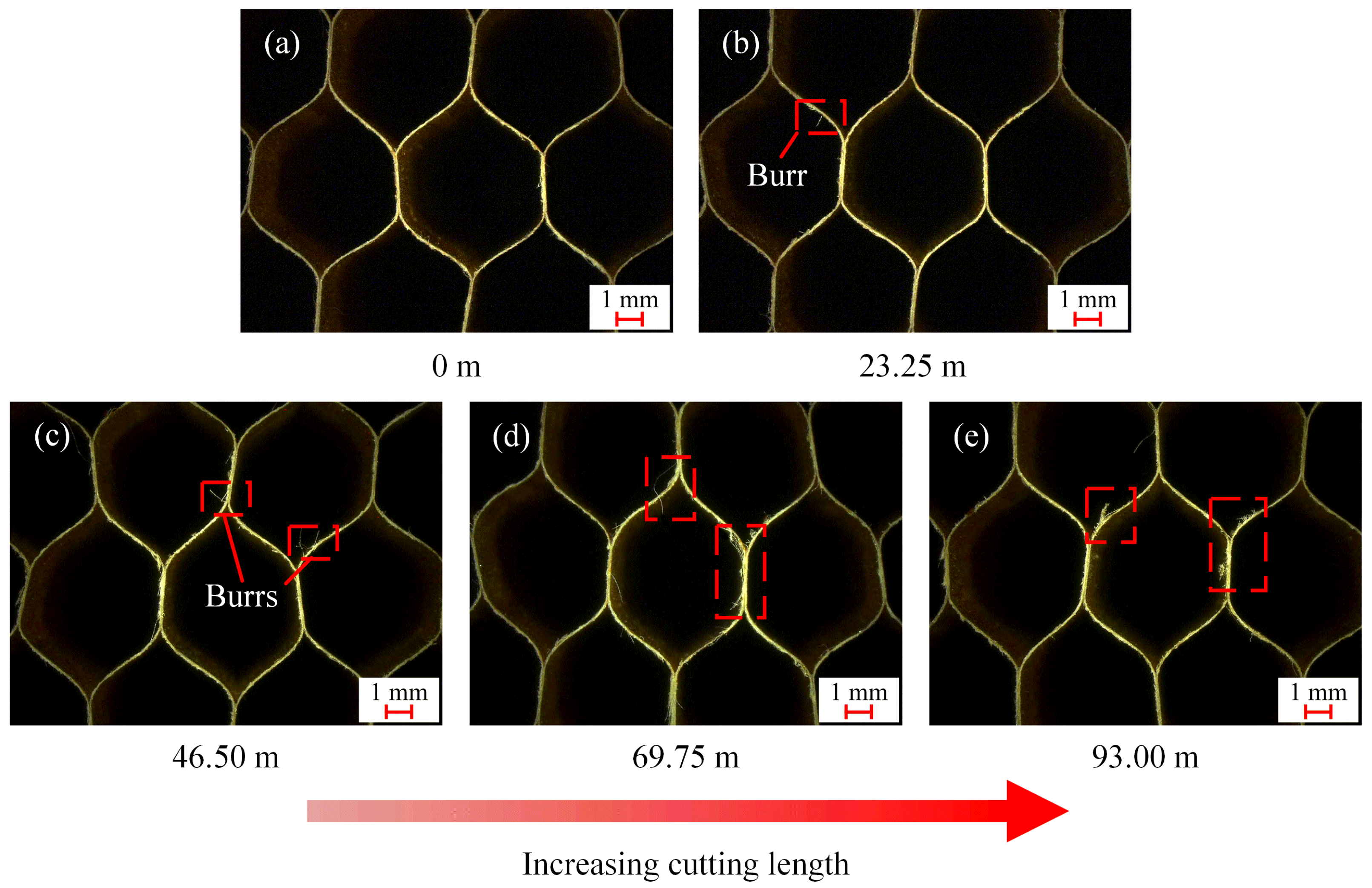
3.3. The Effect of Tool Wear and Breakage on the Surface Quality

By observing the surface quality of conventional cutting and ultrasonic cutting Nomex honeycomb core during each round of experiments, it was found that the length and number of burrs on the honeycomb surface gradually increased as the cutting length increased, and their surface quality both gradually deteriorated. The conventional cutting surface and ultrasonic cutting surface are shown in Figure 22 and Figure 23, respectively. At the cutting length of 23.25 m, the CER was small; the edge was sharp; the wear degree was small; and the disc cutter could cut off the aramid fiber in time and effectively. Hence, at this time, the honeycomb hole wall had been processed with a flatter surface and basically without hole wall burrs, as shown in Figure 22b and Figure 23b. At the cutting length of 46.50 m, the aramid fiber pull-out phenomenon appeared on both the conventional cutting surface and ultrasonic cutting surface, forming the burrs defect, but the burrs were more obvious on the conventional cutting surface, as shown in Figure 22c and Figure 23c. With the increase in tool wear and breakage, the CER of the disc cutter gradually increased, and the width of the cutting edge breakage at the chipping position also further increased. The disc cutter failed to cut off the aramid fiber in time during the cutting process, resulting in a longer aramid fiber pull-out length on the honeycomb wall and an increase in the number of burrs, as shown in Figure 22d,e and Figure 23d,e. Furthermore, comparing the conventional cutting surface and ultrasonic cutting surface with cutting lengths of 69.75 m and 93.00 m, respectively, it is obvious that the number of honeycomb burrs after ultrasonic cutting is less and the surface quality is better. This also indicates that ultrasonic cutting Nomex honeycomb core has some machining advantages under the same cutting condition.

4. Conclusions

In this work, the disc cutter wear and breakage morphologies were observed. The cutting edge rounding (CER) and flank wear VB were introduced to characterize the wear characteristics, and the diameter reduction and the cutting edge breakage width were used to characterize the breakage characteristics of the disc cutter. Additionally, the characterization parameters were used to analyze the disc cutter wear process in the ultrasonic cutting Nomex honeycomb core. The conclusions can be summarized as follows:
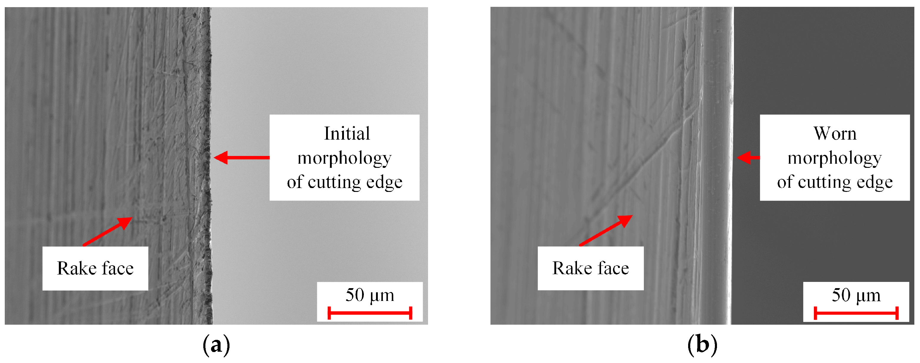
  • The tool wear forms of the disc cutter are mainly cutting edge wear and flank wear. The wear positions are concentrated near the cutting edge, which is shown as the cutting edge dulling and the flank wear band. The CER and the flank wear VB increase with the increase in the cutting length. The CER increases from 3.54 μm to 8.26 μm, and the increasing trend is more significant. The disc cutter wear mechanism is mainly abrasive wear.
  • The tool breakage form of the disc cutter is mainly the cutting edge breakage. The breakage positions are primarily at the cutting edge, which manifests as chipping and cracking breakage. With the increase of cutting length, the width of cutting edge breakage gradually increases; the continuous chipping makes the breakage form of the disc cutter show a band distribution; and the overall diameter of the disc cutter gradually decreases.
  • The length and quantity of burrs on the honeycomb surface increase gradually with the increase in the degree of disc cutter wear and breakage. Ultrasonic cutting results in fewer honeycomb burrs and better surface quality compared to conventional cutting at the same cutting condition.

Author Contributions

Conceptualization, L.L. and Y.W.; methodology, L.L. and Y.W.; software, Y.Q.; validation, R.K., Z.D. and H.S.; formal analysis, Y.Q. and Y.W.; investigation, L.L.; resources, Z.D.; data curation, L.L.; writing—original draft preparation, L.L.; writing—review and editing, Y.W.; visualization, Z.D.; supervision, H.S.; project administration, R.K.; funding acquisition, R.K. All authors have read and agreed to the published version of the manuscript.

Funding

This study was supported by the National Natural Science Foundation of China (Grant No. U20A20291) and Dalian High-Level Talent Innovation Program (Grant No. 2020RD02).

Institutional Review Board Statement

Not applicable.

Informed Consent Statement

Not applicable.

Data Availability Statement

Not applicable.

Acknowledgments

All the authors are greatly acknowledged for their financial support in making this research possible.

Conflicts of Interest

The authors declare no conflict of interest.

References

  1. Wang, Y.D.; Kang, R.K.; Dong, Z.G.; Wang, X.P.; Huo, D.H.; Zhang, X. A Novel Method of Blade-Inclined Ultrasonic Cutting Nomex Honeycomb Core With Straight Blade. J. Manuf. Sci. Eng. 2021, 143, 041012. [Google Scholar] [CrossRef]
  2. Qin, Y.; Kang, R.K.; Dong, Z.G.; Wang, Y.D.; Yang, J.; Zhu, X.L. Burr removal from measurement data of honeycomb core surface based on dimensionality reduction and regression analysis. Meas. Sci. Technol. 2018, 29, 115010. [Google Scholar] [CrossRef]
  3. Rodriguez-Ramirez, J.D.; Castanie, B.; Bouvet, C. Experimental and numerical analysis of the shear nonlinear behaviour of Nomex honeycomb core: Application to insert sizing. Compos. Struct. 2018, 193, 121–139. [Google Scholar] [CrossRef] [Green Version]
  4. Niu, J.; Zhu, X.; Kang, R.; Wang, Y.; Dong, Z. Experimental research on ultrasonic cutting honeycomb cores by disc cutter. Diam. Abras. Eng. 2017, 37, 62–68. [Google Scholar]
  5. Rion, J.; Leterrier, Y.; Manson, J.A.E. Prediction of the adhesive fillet size for skin to honeycomb core bonding in ultra-light sandwich structures. Compos. Part A Appl. Sci. Manuf. 2008, 39, 1547–1555. [Google Scholar] [CrossRef]
  6. Heimbs, S. Virtual testing of sandwich core structures using dynamic finite element simulations. Comp. Mater. Sci. 2009, 45, 205–216. [Google Scholar] [CrossRef]
  7. Ahmad, S.; Zhang, J.F.; Feng, P.F.; Yu, D.W.; Wu, Z.J.; Ke, M. Processing technologies for Nomex honeycomb composites (NHCs): A critical review. Compos. Struct. 2020, 250, 112545. [Google Scholar] [CrossRef]
  8. Yang, Z.C.; Zhu, L.D.; Zhang, G.X.; Ni, C.B.; Lin, B. Review of ultrasonic vibration-assisted machining in advanced materials. Int. J. Mach. Tools Manu. 2020, 156, 103594. [Google Scholar] [CrossRef]
  9. Kang, D.; Zou, P.; Wu, H.; Duan, J.W.; Wang, W.J. Study on ultrasonic vibration-assisted cutting of Nomex honeycomb cores. Int. J. Adv. Manuf. Tech. 2019, 104, 979–992. [Google Scholar] [CrossRef]
  10. Hu, X.P.; Yu, B.H.; Li, X.Y.; Chen, N.C. Research on Cutting Force Model of Triangular Blade for Ultrasonic Assisted Cutting Honeycomb Composites. Proc. Cirp. 2017, 66, 159–163. [Google Scholar] [CrossRef]
  11. Meng, Q.; Wang, Y.D.; Dong, Z.G.; Kang, R.K. Cutting force and surface quality research on ultrasonic cutting of Nomex honeycomb core with disc cutter. Aeronaut. Manuf. Technol. 2021, 64, 88–95. [Google Scholar]
  12. Ahmad, S.; Zhang, J.F.; Feng, P.F.; Yu, D.W.; Wu, Z.J.; Ke, M. Research on Design and FE Simulations of Novel Ultrasonic Circular Saw Blade (UCSB) Cutting Tools for Rotary Ultrasonic Machining of Nomex Honeycomb Composites. In Proceedings of the 2019 16th International Bhurban Conference on Applied Sciences and Technology (IBCAST), Islamabad, Pakistan, 8–12 January 2019; pp. 113–119. [Google Scholar]
  13. Ahmad, S.; Zhang, J.F.; Feng, P.F.; Yu, D.W.; Wu, Z.J. Experimental study on rotary ultrasonic machining (RUM) characteristics of Nomex honeycomb composites (NHCs) by circular knife cutting tools. J. Manuf. Process. 2020, 58, 524–535. [Google Scholar] [CrossRef]
  14. Sun, J.S.; Dong, Z.G.; Wang, Y.D.; Liu, J.T.; Qin, Y.; Kang, R.K. Experimental study on ultrasonic cutting of aluminum honeycombs. J. Mech. Eng. 2017, 53, 128–135. [Google Scholar] [CrossRef]
  15. Sun, J.S.; Dong, Z.G.; Wang, X.P.; Wang, Y.D.; Qin, Y.; Kang, R.K. Simulation and experimental study of ultrasonic cutting for aluminum honeycomb by disc cutter. Ultrasonics 2020, 103, 106102. [Google Scholar] [CrossRef]
  16. Guo, Z.F.; Liu, X.; Yao, S.F.; Yu, B.H.; Hu, X.P.; Ye, H.X. Stability analysis and experimental research on ultrasonic cutting of wave-absorbing honeycomb material with disc cutter. Int. J. Adv. Manuf. Tech. 2022, 120, 1373–1383. [Google Scholar] [CrossRef]
  17. Gill, D.D.; Yip-Hoi, D.M.; Meaker, M.; Boni, T.; Eggeman, E.L.; Brennen, A.M.; Anderson, A. Studying the Mechanisms of High Rates of Tool Wear in the Machining of Aramid Honeycomb Composites. In Proceedings of the Asme 12th International Manufacturing Science and Engineering Conference, Los Angeles, CA, USA, 4–8 June 2017; Volume 2. [Google Scholar]
  18. Jaafar, M.; Makich, H.; Nouari, M. A new criterion to evaluate the machined surface quality of the Nomex (R) honeycomb materials. J. Manuf. Process. 2021, 69, 567–582. [Google Scholar] [CrossRef]
  19. Zha, H.T.; Shang, W.J.; Xu, J.; Feng, F.; Kong, H.Y.; Jiang, E.L.; Ma, Y.; Xu, C.; Feng, P.F. Tool Wear Characteristics and Strengthening Method of the Disc Cutter for Nomex Honeycomb Composites Machining with Ultrasonic Assistance. Technologies 2022, 10, 132. [Google Scholar] [CrossRef]
  20. Wang, Y.D.; Kang, R.K.; Qin, Y.; Meng, Q.; Dong, Z.G. Effects of inclination angles of disc cutter on machining quality of Nomex honeycomb core in ultrasonic cutting. Front. Mech. Eng. 2021, 16, 285–297. [Google Scholar] [CrossRef]
  21. Faraz, A.; Biermann, D.; Weinert, K. Cutting edge rounding: An innovative tool wear criterion in drilling CFRP composite laminates. Int. J. Mach. Tool. Manu. 2009, 49, 1185–1196. [Google Scholar] [CrossRef]
  22. Ramirez, C.; Poulachon, G.; Rossi, F.; M’Saoubi, R. Tool wear monitoring and hole surface quality during CFRP drilling. Procedia CIRP 2014, 13, 163–168. [Google Scholar] [CrossRef] [Green Version]
  23. Madhavan, V.; Lipczynski, G.; Lane, B.; Whitenton, E. Fiber orientation angle effects in machining of unidirectional CFRP laminated composites. J. Manuf. Process. 2015, 20, 431–442. [Google Scholar] [CrossRef] [Green Version]
  24. Wyen, C.F.; Knapp, W.; Wegener, K. A new method for the characterisation of rounded cutting edges. Int. J. Adv. Manuf. Tech. 2012, 59, 899–914. [Google Scholar] [CrossRef] [Green Version]
  25. Chen, Y.L.; Cai, Y.D.; Xu, M.L.; Shimizu, Y.; Ito, S.; Gao, W. An edge reversal method for precision measurement of cutting edge radius of single point diamond tools. Precis. Eng. 2017, 50, 380–387. [Google Scholar] [CrossRef]
  26. Wang, F.J.; Qian, B.W.; Jia, Z.Y.; Fu, R.; Cheng, D. Secondary cutting edge wear of one-shot drill bit in drilling CFRP and its impact on hole quality. Compos. Struct. 2017, 178, 341–352. [Google Scholar] [CrossRef]
  27. Çelik, A.; Lazoglu, I.; Kara, A.; Kara, F. Wear on SiAlON ceramic tools in drilling of aerospace grade CFRP composites. Wear 2015, 338–339, 11–21. [Google Scholar] [CrossRef]
  28. Kieu, S.T.H.; Bade, A.; Hijazi, M.H.A. Modified canny edge detection technique for identifying endpoints. In Journal of Physics: Conference Series; IOP Publishing: Bristol, UK, 2022; Volume 2314. [Google Scholar]
  29. Jiang, J.M.; Liu, Z.Q. Formation mechanism of tearing defects in machining Nomex honeycomb core. Int. J. Adv. Manuf. Tech. 2021, 112, 3167–3176. [Google Scholar] [CrossRef]
  30. Roy, R.; Park, S.J.; Kweon, J.H.; Choi, J.H. Characterization of Nomex honeycomb core constituent material mechanical properties. Compos. Struct. 2014, 117, 255–266. [Google Scholar] [CrossRef]
  31. Yang, W.C.; Zhang, X.F.; Yang, K.J.; Pan, B.; Fei, B.J.; Yi, X.S.; Chen, Y.L. Shear property characterization of aramid paper and its application to the prediction of honeycomb behaviors. Compos. Struct. 2020, 254, 112800. [Google Scholar] [CrossRef]
  32. Su, H.; Liu, P.; Fu, Y.; Xu, J. Tool Life and Surface Integrity in High-speed Milling of Titanium Alloy TA15 with PCD/PCBN Tools. Chin. J. Aeronaut. 2012, 25, 784–790. [Google Scholar] [CrossRef] [Green Version]
Figure 1. Disc cutter structure and its geometric parameters. (a) Disc cutter; (b) Disc cutter geometric parameters.
Applsci 13 08168 g001
Figure 2. Ultrasonic cutting wear experiment device and cutting schematic diagram of disc cutter.
Applsci 13 08168 g002
Figure 3. Ultrasonic amplitude measured by point laser measurement system.
Applsci 13 08168 g003
Figure 4. The flow chart of CER calculation.
Applsci 13 08168 g004
Figure 5. Indentation profile curves at different positions.
Applsci 13 08168 g005
Figure 6. Fixture for disc cutter inspection and the measurement of flank wear VB. (a) Fixture for disc cutter inspection; (b) Flank wear VB.
Applsci 13 08168 g006
Figure 7. The flow chart of diameter reduction calculation.
Applsci 13 08168 g007
Figure 8. Point cloud scanning of the flank face of the disc cutter.
Applsci 13 08168 g008
Figure 9. The measurement method of cutting edge breakage width.
Applsci 13 08168 g009
Figure 10. SEM morphologies of cutting edge wear. (a) Initial morphology of cutting edge; (b) Worn morphology of cutting edge.
Applsci 13 08168 g010
Figure 11. Variation of CER with cutting length.
Applsci 13 08168 g011
Figure 12. Wear morphologies of disc cutter at the same cutting position under different cutting lengths.
Applsci 13 08168 g012
Figure 13. Flank wear band SEM observation and EDS result analysis of the position 3. (a) Flank wear band; (b) The energy spectrum analysis of zone A.
Applsci 13 08168 g013
Figure 14. Variation of flank wear VB of position 3 with cutting length.
Applsci 13 08168 g014
Figure 15. Breakage morphologies of disc cutter. (a) Chipping; (b) Crack breakage.
Applsci 13 08168 g015
Figure 16. Variation of diameter reduction with cutting length.
Applsci 13 08168 g016
Figure 17. Chipping morphologies of disc cutter at the same cutting position under different cutting lengths. (a) 0 m; (b) 23.25 m; (c) 46.50 m; (d) 69.75 m; (e) 93.00 m.
Applsci 13 08168 g017
Figure 18. SEM observation of continuous chipping and cracks (cutting length is 93.00 m).
Applsci 13 08168 g018
Figure 19. Breakage morphologies of disc cutter at the same cutting position 1 under different cutting lengths. (a) 0 m; (b) 23.25 m; (c) 46.50 m; (d) 69.75 m; (e) 93.00 m.
Applsci 13 08168 g019
Figure 20. Breakage morphologies of disc cutter at the same cutting position 2 under different cutting lengths. (a) 0 m; (b) 23.25 m; (c) 46.50 m; (d) 69.75 m; (e) 93.00 m.
Applsci 13 08168 g020
Figure 21. Variation of the cutting edge breakage width with cutting length.
Applsci 13 08168 g021
Figure 22. Conventional cutting machining surface with disc cutter under different cutting lengths. (a) 0 m; (b) 23.25 m; (c) 46.50 m; (d) 69.75 m; (e) 93.00 m.
Applsci 13 08168 g022
Figure 23. Ultrasonic cutting machining surface with disc cutter under different cutting lengths. (a) 0 m; (b) 23.25 m; (c) 46.50 m; (d) 69.75 m; (e) 93.00 m.
Applsci 13 08168 g023
Table 1. Disc cutter parameters.
Tool MaterialDiameter
D (mm)
Wedge Angle
β (°)
Rake Angle
γ (°)
Clearance Angle
α (°)
Tool Thickness
(mm)
W2Mo9Cr4VCo850.815.5731.52
Table 2. Disc cutter wear experiment parameters.
Spindle Speed
n
(r/min)
Feed Speed
Vf
(mm/min)
Depth of Cut
ap
(mm)
Width of Cut
ae
(mm)
Ultrasonic Frequency
(kHz)
Ultrasonic Amplitude
A (μm)
1000100011522.415
Table 3. Comparison of wear morphology characteristics of disc cutter.
Disc Cutter Observation
Position
Characteristics of Initial
Morphology
Characteristics of Worn
Morphology
Applsci 13 08168 i001Applsci 13 08168 i002Applsci 13 08168 i003
Applsci 13 08168 i004Applsci 13 08168 i005Applsci 13 08168 i006
Disclaimer/Publisher’s Note: The statements, opinions and data contained in all publications are solely those of the individual author(s) and contributor(s) and not of MDPI and/or the editor(s). MDPI and/or the editor(s) disclaim responsibility for any injury to people or property resulting from any ideas, methods, instructions or products referred to in the content.

